EP0091428B1 - Pump element of an artificial breathing device - Google Patents
Pump element of an artificial breathing device Download PDFInfo
- Publication number
- EP0091428B1 EP0091428B1 EP81902840A EP81902840A EP0091428B1 EP 0091428 B1 EP0091428 B1 EP 0091428B1 EP 81902840 A EP81902840 A EP 81902840A EP 81902840 A EP81902840 A EP 81902840A EP 0091428 B1 EP0091428 B1 EP 0091428B1
- Authority
- EP
- European Patent Office
- Prior art keywords
- hollow body
- pump element
- air
- hand
- depressions
- Prior art date
- Legal status (The legal status is an assumption and is not a legal conclusion. Google has not performed a legal analysis and makes no representation as to the accuracy of the status listed.)
- Expired
Links
Images
Classifications
-
- A—HUMAN NECESSITIES
- A61—MEDICAL OR VETERINARY SCIENCE; HYGIENE
- A61M—DEVICES FOR INTRODUCING MEDIA INTO, OR ONTO, THE BODY; DEVICES FOR TRANSDUCING BODY MEDIA OR FOR TAKING MEDIA FROM THE BODY; DEVICES FOR PRODUCING OR ENDING SLEEP OR STUPOR
- A61M16/00—Devices for influencing the respiratory system of patients by gas treatment, e.g. mouth-to-mouth respiration; Tracheal tubes
- A61M16/0057—Pumps therefor
- A61M16/0078—Breathing bags
-
- A—HUMAN NECESSITIES
- A61—MEDICAL OR VETERINARY SCIENCE; HYGIENE
- A61M—DEVICES FOR INTRODUCING MEDIA INTO, OR ONTO, THE BODY; DEVICES FOR TRANSDUCING BODY MEDIA OR FOR TAKING MEDIA FROM THE BODY; DEVICES FOR PRODUCING OR ENDING SLEEP OR STUPOR
- A61M16/00—Devices for influencing the respiratory system of patients by gas treatment, e.g. mouth-to-mouth respiration; Tracheal tubes
- A61M16/0057—Pumps therefor
- A61M16/0084—Pumps therefor self-reinflatable by elasticity, e.g. resuscitation squeeze bags
Definitions
- the invention relates to a manually operated pump element of a device for artificial ventilation of people, which consists of a gas-tight, elastic, self-expanding and preferably elongated hollow body with a substantially circular cross section and has two tubular connecting pieces as an air inlet or outlet opening.
- the hollow body is of single or multi-walled design and a valve element acting as a suction valve is arranged in or on the connecting piece serving as an air inlet opening.
- a line leading to the person to be ventilated, the patient, into which a three-way valve, the patient valve, is inserted, is connected to the other connection piece, the air outlet opening.
- air or gas is pressed out of the hollow body manually into the patient's lungs via the air outlet opening and the line with the patient valve.
- the suction valve in the air inlet opening of the hollow body is closed.
- the compressed hollow body If the compressed hollow body is relieved, it takes on its original shape again due to its self-expanding properties and fills with air from the environment or another gas via the suction valve, which is supplied to the air inlet opening from a reservoir.
- the patient valve prevents gas or air from flowing out of the patient's lungs back into the hollow body and at the same time creates a connection with the atmosphere into which the exhaled air is discharged.
- Another possibility of protecting patients from damage resulting from the operation of the pump element during artificial ventilation is to limit the amount of air released during the compression of the pump element.
- FR-A-1 161 194 describes a device for artificial respiration which has a bellows as a pump element which can be compressed with a handle against the force of a spring.
- a bladder is attached in a gastight manner over the handle, which is designed as a perforated tube, and is also compressed when the bellows is compressed by acting on the handle with one hand in order to ventilate a person.
- the air from the bladder is fed via the handle and a line to the ventilation valve in order to move its valve body and thus to open the passage for the ventilation air from the bellows into the patient's lungs.
- the wall of the bladder made of rubber is provided with six reinforcing ribs arranged evenly over its circumference, which rapidly inflate the bladder compressed with one hand after the handle and thus the bladder have been released in order to fill the ball with a new breathing process.
- This pressure relief of the bladder has the result that the valve body of the ventilation valve returns to its starting position, so that the patient can exhale through the ventilation valve.
- This device also has the disadvantages described above, since the amount of air supplied to the patient from the bellows cannot be controlled.
- the object of the invention is now to provide a manually operated pump element of a device for art lichen ventilation of people so that it can be used in the treatment of both children and adults without the risk of pressure overload of their lungs.
- the handling of the pump element is very simple; because the hollow body only has to be gripped so that the thumb and the tips of the other fingers of one hand each lie in a recess.
- the hollow body in order to supply the patient with air, is compressed and deflated or, due to its self-expanding properties, inflated and refilled with unused air.
- the hollow body can be gripped so that the palm and fingers span either about 120 angular degrees or 240 angular degrees of the circumference of the jacket of the hollow body, so that about a third or two thirds of it is emptied when the hollow body is compressed.
- the volume of the hollow body is dimensioned so that the smaller amount of air delivered is adapted to the breathing capacity of a child and the larger amount of air to the volume of the lungs of an adult person. Since the two possibilities for detecting the hollow body differ markedly and the fingers of the pumping hand are well guided in the indentations of the hollow body, it is ensured in the simplest manner without great technical effort that the lungs of a patient are not damaged during artificial ventilation.
- the self-expansion forces of the hollow body should be so great that it compresses at a speed corresponding to at least the respiratory rate even if an operating error delays the deployment.
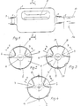
- the device for artificial respiration of humans shown in FIG. 1 has as pump element an essentially cylindrical hollow body 1, which is made of a gas-tight, elastic material with self-expanding properties.
- hollow body 1 On the hollow body 1 two nozzles 2 and 4 are worked as air inlet and air outlet openings.
- a suction valve 3 is connected to the nozzle 2, while the nozzle 4 is connected to a patient valve 5.
- two axially extending indentations 6 and 7 are incorporated, which are approximately 120 degrees apart from one another in relation to the cross section of the hollow body (angle AB, FIGS. 2, 3 and 4).
- the wall thereof can have depressions 10 (FIG. 3) and / or beads 11 (FIG. 4) extending parallel to the indentations 6 and 7.
- an air quantity of 800 to 1,000 cm 3 is supplied to the patient via the patient valve 5 when the hand is clenched. This is the amount of air that an adult person during every breath can be absorbed with artificial respiration without danger to the lungs.
- the hollow body 1 forming the pump element can, according to the invention, not only have the shape described in the figures, but, for. B. also be designed as a ball or ellipsoid, provided that the indentations 6 and 7 are arranged so that when handling the hollow body 1 in the manner described, this is either about a third or two thirds emptied.
Landscapes
- Health & Medical Sciences (AREA)
- Pulmonology (AREA)
- Emergency Medicine (AREA)
- Engineering & Computer Science (AREA)
- Anesthesiology (AREA)
- Biomedical Technology (AREA)
- Heart & Thoracic Surgery (AREA)
- Hematology (AREA)
- Life Sciences & Earth Sciences (AREA)
- Animal Behavior & Ethology (AREA)
- General Health & Medical Sciences (AREA)
- Public Health (AREA)
- Veterinary Medicine (AREA)
- Critical Care (AREA)
- Respiratory Apparatuses And Protective Means (AREA)
- Prostheses (AREA)
- External Artificial Organs (AREA)
Abstract
Description
Die Erfindung betrifft ein handbetätigtes Pumpelement einer Vorrichtung zur künstlichen Beatmung von Menschen, das aus einem gasdichten, elastischen, selbstexpandierenden und vorzugsweise langgestreckten Hohlkörper mit im wesentlichen kreisförmigem Querschnitt besteht und zwei rohrförmige Stutzen als Lufteintritts- bzw. -austrittsöffnung aufweist.The invention relates to a manually operated pump element of a device for artificial ventilation of people, which consists of a gas-tight, elastic, self-expanding and preferably elongated hollow body with a substantially circular cross section and has two tubular connecting pieces as an air inlet or outlet opening.
Bei derartigen bekannten Pumpelementen (US-A-3 046 978) ist der Hohlkörper ein- oder mehrwandig ausgebildet und im oder am als Lufteintrittsöffnung dienenden Stutzen ein als Saugventil wirkendes Ventilelement angeordnet. An den anderen Stutzen, die Luftaustrittsöffnung, ist eine zur zu beatmenden Person, dem Patienten, führende Leitung angeschlossen, in die ein Dreiwegeventil, das Patientenventil, eingefügt ist. Bei künstlicher Beatmung wird durch manuelles Zusammendrücken des Hohlkörpers Luft oder Gas aus demselben über die Luftaustrittsöffnung und die Leitung mit dem Patientenventil, in die Lunge des Patienten gepreßt. Dabei ist das Saugventil in der Lufteintrittsöffnung des Hohlkörpers geschlossen. Wird der zusammengedrückte Hohlkörper entlastet, nimmt dieser aufgrund seiner selbstexpandierenden Eigenschaften seine ursprüngliche Gestalt wieder an und füllt sich über das Saugventil mit Luft aus der Umgebung oder einem anderen Gas, das aus einem Speicher der Lufteintrittsöffnung zugeführt wird. Dabei verhindert das Patientenventil, daß Gas oder Luft aus der Lunge des Patienten zurück in den Hohlkörper strömt, und schafft zugleich eine Verbindung mit der Atmosphäre, in die die ausgeatmete Luft abgeleitet wird.In such known pump elements (US-A-3 046 978) the hollow body is of single or multi-walled design and a valve element acting as a suction valve is arranged in or on the connecting piece serving as an air inlet opening. A line leading to the person to be ventilated, the patient, into which a three-way valve, the patient valve, is inserted, is connected to the other connection piece, the air outlet opening. In the case of artificial ventilation, air or gas is pressed out of the hollow body manually into the patient's lungs via the air outlet opening and the line with the patient valve. The suction valve in the air inlet opening of the hollow body is closed. If the compressed hollow body is relieved, it takes on its original shape again due to its self-expanding properties and fills with air from the environment or another gas via the suction valve, which is supplied to the air inlet opening from a reservoir. The patient valve prevents gas or air from flowing out of the patient's lungs back into the hollow body and at the same time creates a connection with the atmosphere into which the exhaled air is discharged.
Der Einsatz solcher Pumpelemente ist mit der Gefahr verbunden, daß dem Patienten mehr Luft zugeführt wird, als dessen Lunge während eines Atemzuges aufnehmen kann, wodurch dieser Person schwere Schäden durch eine druckmäßige Überlastung der Lunge zugefügt werden. Diese Gefahr ist besonders groß, wenn mit dem gleichen Pumpelement Patienten mit sehr verschiedenen Lungenvolumen wie Kinder und Erwachsene künstlich beatmet werden. Dieser Gefahr wird dadurch begegnet, daß die Pumpelemente mit Druckbegrenzern in Form von Überdruckventilen ausgerüstet sind. Überdruckventile sind jedoch sehr unzuverlässig und blockieren leicht, wodurch der druckbegrenzende Effekt entfällt. Ein anderer Nachteil dieser Druckbegrenzer besteht darin, daß der Öffnungsdruck zu niedrig eingestellt ist. Dies kann dazu führen, daß der Widerstand in den Luftwegen des Patienten nicht überwunden und somit keine Beatmung erhalten wird.The use of such pump elements is associated with the risk that more air is supplied to the patient than his lungs can absorb during a breath, as a result of which severe damage is caused to this person by pressure overloading the lungs. This risk is particularly great if patients with very different lung volumes, such as children and adults, are artificially ventilated with the same pump element. This danger is countered by the fact that the pump elements are equipped with pressure limiters in the form of pressure relief valves. Pressure relief valves are very unreliable and block easily, which eliminates the pressure-limiting effect. Another disadvantage of these pressure limiters is that the opening pressure is set too low. This can result in the resistance in the patient's airways not being overcome and therefore no ventilation being obtained.
Eine andere Möglichkeit, Patienten während der künstlichen Beatmung vor Schäden zu bewahren, die von der Bedienung des Pumpelementes herrühren, ist die Begrenzung der während des Zusammendrückens des Pumpelementes abgegebenen Luftmenge. Bei dem in derAnother possibility of protecting patients from damage resulting from the operation of the pump element during artificial ventilation is to limit the amount of air released during the compression of the pump element. The one in the
US-PS-3 046 978 beschriebenen Pumpelement geschieht dies dadurch, daß in den Hohlkörper an bestimmten Stellen zwei elastische Kugeln verschiedener Größe angeordnet sind, die das Zusammendrücken des Hohlkörpers begrenzen. Der Hohlkörper trägt auf seiner Außenseite der Lage der Kugeln entsprechende Markierungen, die Griffzonen begrenzen. Jeder Griffzone ist somit ein bestimmtes Luftvolumen zugeordnet, das in etwa der Lungenkapazität von Kindern ; Jugendlichen und Erwachsenen entspricht. Diese Griffzonen sind nur optisch wahrzunehmen, was insbesondere bei der Beatmung von Personen an schlecht beleuchteten Unfallstellen zu fehlerhafter Handhabung des Pumpelementes und damit zur Schädigung des Patienten führen kann. Dieser Nachteil wird noch dadurch vergrößert, daß das Pumpelement doppelwandig ist und vor Gebrauch in den Raum zwischen seinen Wandungen Luft eingeblasen werden soll. Dies setzt voraus, daß der Innenbeutel des Pumpelementes vom Luftdruck im Zwischenraum nicht zusammengepreßt wird, was nur mit verhältnismäßig großen Selbstexpansionskräften in dessen Wandung zu erreichen ist. Diese Kräfte bewirken aber, daß sich das Pumpelement relativ schwer betätigen läßt, so daß dessen Benutzer den erzeugten Beatmungsdruck nicht fühlt, was zur Verhinderung einer sachgemäßen Beatmung des Patienten beiträgt.Pump element described in US Pat. No. 3,046,978 does this by arranging two elastic balls of different sizes in certain places in the hollow body, which limit the compression of the hollow body. The outside of the hollow body has markings corresponding to the position of the balls, which delimit grip zones. Each grip zone is thus assigned a certain volume of air, which is roughly the lung capacity of children; Corresponds to adolescents and adults. These grip zones can only be perceived visually, which can lead to incorrect handling of the pump element and thus damage to the patient, particularly when ventilating people at poorly lit accident sites. This disadvantage is exacerbated by the fact that the pump element is double-walled and air is to be blown into the space between its walls before use. This presupposes that the inner bag of the pump element is not compressed by the air pressure in the intermediate space, which can only be achieved with relatively large self-expansion forces in the wall thereof. However, these forces make the pump element relatively difficult to operate, so that its user does not feel the ventilation pressure generated, which helps prevent proper ventilation of the patient.
In der FR-A-1 161 194 wird noch eine Vorrichtung zur künstlichen Beatmung beschrieben, die als Pumpelement einen Balg aufweist, der mit einem Handgriff gegen die Kraft einer Feder zusammengedrückt werden kann. Über dem als perforiertes Rohr ausgebildeten Handgriff ist eine Blase gasdicht befestigt, die beim Zusammendrücken des Balges, indem mit einer Hand auf den Handgriff eingewirkt wird, um eine Person zu beatmen, ebenfalls zusammengedrückt wird. Hierdurch wird die Luft aus der Blase über den Handgriff und eine Leitung dem Beatmungsventil zugeführt, um dessen Ventilkörper zu verschieben und so den Durchgang für die Beatmungsluft aus dem Balg in die Lunge des Patienten freizugeben. Die Wandung der aus Gummi bestehenden Blase ist mit sechs gleichmäßig über deren Umfang angeordneten Verstärkungsrippen versehen, die ein schnelles Aufblähen der mit einer Hand zusammengedrückten Blase bewirken, nachdem der Handgriff und damit die Blase losgelassen wurde, um den Bal einen neuen Atemvorgang zu füllen. Diese Druckentlastung der Blase hat zur Folge, daß der Ventilkörper des Beatmungsventiles in seine Ausgangsstellung zurückkehrt, so daß der Patient über das Beatmungsventil ausatmen kann. Dieser Vorrichtung haften ebenfalls die vorstehend geschilderten Nachteile an, da die dem Patienten aus dem Balg zugeführte Luft mengenmäßig nicht gesteuert werden kann.FR-A-1 161 194 describes a device for artificial respiration which has a bellows as a pump element which can be compressed with a handle against the force of a spring. A bladder is attached in a gastight manner over the handle, which is designed as a perforated tube, and is also compressed when the bellows is compressed by acting on the handle with one hand in order to ventilate a person. As a result, the air from the bladder is fed via the handle and a line to the ventilation valve in order to move its valve body and thus to open the passage for the ventilation air from the bellows into the patient's lungs. The wall of the bladder made of rubber is provided with six reinforcing ribs arranged evenly over its circumference, which rapidly inflate the bladder compressed with one hand after the handle and thus the bladder have been released in order to fill the ball with a new breathing process. This pressure relief of the bladder has the result that the valve body of the ventilation valve returns to its starting position, so that the patient can exhale through the ventilation valve. This device also has the disadvantages described above, since the amount of air supplied to the patient from the bellows cannot be controlled.
Aufgabe der Erfindung ist es nun, ein handbetätigtes Pumpelement einer Vorrichtung zur künstlichen Beatmung von Menschen so auszubilden, daß es sowohl bei der Behandlung von Kindern als auch Erwachsenen ohne das Risiko einer druckmäßigen Überlastung von deren Lungen eingesetzt werden kann.The object of the invention is now to provide a manually operated pump element of a device for art lichen ventilation of people so that it can be used in the treatment of both children and adults without the risk of pressure overload of their lungs.
Diese Aufgabe wird erfindungsgemäß ausgehend von einem Pumpelement der eingangs beschriebenen Gattung dadurch gelöst, daß in die Wandung des Hohlkörpers zwei sich in axialer Richtung erstreckende Einbuchtungen eingearbeitet sind, die auf den Querschnitt des Hohlkörpers bezogen etwa 100 bis 140 Winkelgrad vorzugsweise etwa 120 Winkelgrad voneinander entfernt sind und zwei Griffzonen unmittelbar festlegen. Jede dieser Einbuchtungen ist zweckmäßigerweise so groß, daß der Daumen oder sämtliche Spitzen der anderen Finger einer Hand in sie eingreifen können.This object is achieved on the basis of a pump element of the type described in the introduction in that two indentations extending in the axial direction are incorporated into the wall of the hollow body, which are approximately 100 to 140 angular degrees, preferably approximately 120 angular degrees apart, based on the cross section of the hollow body and define two grip zones immediately. Each of these indentations is expediently so large that the thumb or all tips of the other fingers of one hand can engage in them.
Die Handhabung des Pumpelementes ist denkbar einfach ; denn der Hohlkörper muß nur so ergriffen werden, daß der Daumen und die Spitzen der anderen Finger einer Hand in je einer Einbuchtung liegen. Durch Zusammenballen oder Öffnen der Hand wird der Hohlkörper, um den Patienten mit Luft zu versorgen, zusammengedrückt und entleert bzw. aufgrund seiner selbstexpandierenden Eigenschaften aufgebläht und wieder mit unverbrauchter Luft gefüllt. Dabei kann der Hohlkörper so ergriffen werden, daß Handfläche und Finger entweder etwa 120 Winkelgrad oder 240 Winkelgrad des Mantelumfanges des Hohlkörpers überspannen, wodurch beim Zusammendrücken des Hohlkörpers dieser zu etwa einem Drittel oder zwei Dritteln entleert wird. Das Volumen des Hohlkörpers ist dabei so bemessen, daß die kleinere abgegebene Luftmenge an die Atemkapazität eines Kindes und die größere Luftmenge an das Lungenvolumen einer erwachsenen Person angepaßt ist. Da die zwei Möglichkeiten zum Erfassen des Hohlkörpers sich auffällig unterscheiden und die Finger der pumpenden Hand in den Einbuchtungen des Hohlkörpers gut geführt sind, wird ohne großen technischen Aufwand auf einfachste Weise sichergestellt, daß die Lunge eines Patienten während der künstlichen Beatmung nicht geschädigt wird.The handling of the pump element is very simple; because the hollow body only has to be gripped so that the thumb and the tips of the other fingers of one hand each lie in a recess. By clenching or opening the hand, the hollow body, in order to supply the patient with air, is compressed and deflated or, due to its self-expanding properties, inflated and refilled with unused air. The hollow body can be gripped so that the palm and fingers span either about 120 angular degrees or 240 angular degrees of the circumference of the jacket of the hollow body, so that about a third or two thirds of it is emptied when the hollow body is compressed. The volume of the hollow body is dimensioned so that the smaller amount of air delivered is adapted to the breathing capacity of a child and the larger amount of air to the volume of the lungs of an adult person. Since the two possibilities for detecting the hollow body differ markedly and the fingers of the pumping hand are well guided in the indentations of the hollow body, it is ensured in the simplest manner without great technical effort that the lungs of a patient are not damaged during artificial ventilation.
Zur Vermeidung von möglicherweise kritischen Störungen während der künstlichen Beatmung sollen die Selbstexpansionskräfte des Hohlkörpers so groß sein, daß dieser sich nach dem Zusammendrücken mit einer mindestens der Atemfrequenz entsprechenden Geschwindigkeit auch dann entfaltet, wenn ein Bedienungsfehler das Entfalten verzögert. Andererseits ist es erwünscht, die Wandung des Hohlkörpers so dünn wie möglich zu bemessen, um insbesondere geübten Personen, den von ihnen beim Zusammendrücken des Hohlkörpers erzeugten Beatmungs-oder Ventilationsdruck fühlen zu lassen. Um dies zu erreichen, hat es sich bewährt, in die Wandung des Hohlkörpers sich zu den Einbuchtungen parallel erstreckende Vertiefungen und/oder Wülste einzuarbeiten.In order to avoid potentially critical disturbances during artificial respiration, the self-expansion forces of the hollow body should be so great that it compresses at a speed corresponding to at least the respiratory rate even if an operating error delays the deployment. On the other hand, it is desirable to dimension the wall of the hollow body as thin as possible, so that, in particular, experienced people can feel the ventilation or ventilation pressure generated by them when the hollow body is compressed. In order to achieve this, it has proven useful to incorporate depressions and / or beads extending parallel to the indentations in the wall of the hollow body.
Ausführungsbeispiele der Erfindung werden noch an Hand der Zeichnungen beschrieben. Es stellen dar:
Figur 1 eine schematische Ansicht einer Vorrichtung zur künstlichen Beatmung von Menschen mit einem handbetätigten Pumpelement nach der Erfindung,Figur 2 eine schematische Schnittansicht längs der Linie I-I durch das Pumpelement nach Fig. 1,- Figur 3 eine Ansicht gemäß Fig. 2 durch ein anderes Pumpelement,
Figur 4 eine Ansicht gemäß Fig. 2 durch ein weiteres Pumpelement.
- FIG. 1 shows a schematic view of a device for artificial ventilation of people with a manually operated pump element according to the invention,
- FIG. 2 shows a schematic sectional view along line II through the pump element according to FIG. 1,
- FIG. 3 shows a view according to FIG. 2 through another pump element,
- 4 shows a view according to FIG. 2 through a further pump element.
Die in Fig. 1 gezeigte Vorrichtung zur künstlichen Beatmung von Menschen weist als Pumpelement einen im wesentlichen zylindrischen Hohlkörper 1 auf, der aus einem gasdichten, elastischen Werkstoff mit selbstexpandierenden Eigenschaften gefertigt ist. An den Hohlkörper 1 sind zwei Stutzen 2 bzw. 4 als Lufteintritts- bzw. Luftaustrittsöffnungen angearbeitet. An den Stutzen 2 ist ein Saugventil 3 angeschlossen, während der Stutzen 4 mit einem Patientenventil 5 in Verbindung steht. In die Wandung des Hohlkörpers 1 sind zwei sich axial erstreckende Einbuchtungen 6 und 7 eingearbeitet, die bezogen auf den Querschnitt des Hohlkörpers etwa 120 Winkelgrad voneinander entfernt sind (Winkel AB, Fig. 2, 3 und 4).The device for artificial respiration of humans shown in FIG. 1 has as pump element an essentially cylindrical
Zur Verbesserung der selbstexpandierenden Eigenschaften des Hohlkörpers 1 kann dessen Wandung sich parallel zu den Einbuchtungen 6 und 7 erstreckende Vertiefungen 10 (Fig.3) und/ oder Wülste 11 (Fig. 4) aufweisen.To improve the self-expanding properties of the
Im folgenden wird noch kurz die Handhabung und Funktion des dargestellten Pumpelementes erläutert :
- Wird der
Hohlkörper 1 mit einer Hand so erfaßt, daß die Handfläche sich über denAbschnitt 8 desHohlkörpers 1 erstreckt und der Daumen sowie die Spitzen der anderen Finger in dieEinbuchtungen 6 bzw. 7 greifen, kann beim Zusammenballen der Hand zu einem Drittel der imHohlkörper 1 vorhandenen Luft aus diesem heraus-und über denStutzen 4 und denAusgang 12 des Patientenventils 5 in die Lunge des Patienten gepreßt werden. Dabei ist das Saugventil 3 geschlossen und beträgt die vomHohlkörper 1 abgegebene Luftmenge etwa 200 bis 400 cm3. Diese Luftmenge ist so gering, daß während der Beatmung eine Schädigung der Lunge eines Kindes nicht zu befürchten ist. Beim Öffnen der Hand entfaltet sich derHohlkörper 1 und füllt sich über das Saugventil 3 wieder mit Luft. Während dieser Zeit atmet der Patient über denAusgang 12 des Patientenventils 5 aus, das ein Rückströmen der verbrauchten Luft in denHohlkörper 1 verhindert und diese über denAnschluß 13 an die Umgebung ableitet.
- If the
hollow body 1 is grasped with one hand so that the palm extends over thesection 8 of thehollow body 1 and the thumb and the tips of the other fingers engage in theindentations Hollow body 1 existing air out of this and are pressed into the patient's lungs via theconnector 4 and theoutlet 12 of the patient valve 5. The suction valve 3 is closed and the amount of air emitted by thehollow body 1 is approximately 200 to 400 cm 3 . This amount of air is so small that there is no risk of damage to a child's lungs during ventilation. When the hand is opened, thehollow body 1 unfolds and fills with air again via the suction valve 3. During this time, the patient exhales through theoutlet 12 of the patient valve 5, which prevents the used air from flowing back into thehollow body 1 and discharges it to the environment via theconnection 13.
Erstreckt sich die Fläche der den Hohlkörper 1 ergreifenden Hand über dessen Abschnitt 9, wird beim Zusammenballen der Hand eine Luftmenge von 800 bis 1 000 cm3 dem Patienten über das Patientenventil 5 zugeführt. Dies ist die Luftmenge, die eine erwachsene Person während jedes Atemzuges bei künstlicher Beatmung ohne Gefahr für die Lunge aufnehmen kann. Der das Pumpelement bildende Hohlkörper 1 kann erfingungsgemäß nicht nur die in den Figuren beschriebene Gestalt haben, sondern z. B. auch als Kugel oder Ellipsoid ausgebildet sein, sofern die Einbuchtungen 6 und 7 so angeordnet sind, daß bei der Handhabung des Hohlkörpers 1 in der beschriebenen Weise dieser entweder etwa zu einem Drittel oder zwei Dritteln entleert wird.If the surface of the hand gripping the
Claims (3)
Applications Claiming Priority (1)
| Application Number | Priority Date | Filing Date | Title |
|---|---|---|---|
| PCT/EP1981/000167 WO1983001386A1 (en) | 1981-10-21 | 1981-10-21 | Pump element of an artificial breathing device |
Publications (2)
| Publication Number | Publication Date |
|---|---|
| EP0091428A1 EP0091428A1 (en) | 1983-10-19 |
| EP0091428B1 true EP0091428B1 (en) | 1986-12-30 |
Family
ID=8164827
Family Applications (1)
| Application Number | Title | Priority Date | Filing Date |
|---|---|---|---|
| EP81902840A Expired EP0091428B1 (en) | 1981-10-21 | 1981-10-21 | Pump element of an artificial breathing device |
Country Status (6)
| Country | Link |
|---|---|
| US (1) | US4537191A (en) |
| EP (1) | EP0091428B1 (en) |
| DE (1) | DE3175736D1 (en) |
| FI (1) | FI69406C (en) |
| NO (1) | NO155123C (en) |
| WO (1) | WO1983001386A1 (en) |
Cited By (1)
| Publication number | Priority date | Publication date | Assignee | Title |
|---|---|---|---|---|
| DE4341746C1 (en) * | 1993-12-08 | 1995-03-02 | Heraeus Instr Gmbh | Ventilation bag |
Families Citing this family (4)
| Publication number | Priority date | Publication date | Assignee | Title |
|---|---|---|---|---|
| EP0466886A1 (en) * | 1990-02-08 | 1992-01-22 | RIESEN, Peter | Artificial respiration device |
| US5483955A (en) * | 1994-09-27 | 1996-01-16 | Respironics, Inc. | Oxygen reservoir bag for a squeeze bag resuscitator |
| US8584311B2 (en) * | 2010-07-07 | 2013-11-19 | Del Lathim | Hand-operable vacuum device |
| USD981567S1 (en) * | 2020-12-18 | 2023-03-21 | Hamilton Medical Ag | Part of an artificial lung ventilation apparatus |
Family Cites Families (11)
| Publication number | Priority date | Publication date | Assignee | Title |
|---|---|---|---|---|
| FR448923A (en) * | 1911-12-09 | 1913-02-13 | David Bognier | Rubber pear enhancements |
| BE551666A (en) * | 1955-10-12 | |||
| GB901315A (en) * | 1959-01-06 | 1962-07-18 | British Oxygen Co Ltd | Improvements in gas pumps of the flexible bag type |
| US3356100A (en) * | 1962-11-07 | 1967-12-05 | Gerda A Seeler | Breathing control valve and operator therefor |
| US3473529A (en) * | 1966-05-23 | 1969-10-21 | Air Reduction | Squeeze-bag resuscitator |
| SE345201B (en) * | 1968-07-08 | 1972-05-23 | Hesse R | |
| IT1003974B (en) * | 1974-04-02 | 1976-06-10 | Bioengineering Research | DEPRESSIBLE TUBULAR DUCT PARTICULARLY FOR USE IN DEVICES ABLE TO CREATE EXTRA-BODY BLOOD CIRCULATION REA TRANSFUSIONS, HEMODIALYSIS AND SIMILAR |
| US4077404A (en) * | 1975-09-17 | 1978-03-07 | H. B. W. Medical Instruments Manufacturing Company, Inc. | Breathing equipment such as resuscitators |
| PL106283B1 (en) * | 1976-07-13 | 1979-12-31 | Aparatury Rentgenowskiej I Urz | MANUAL RESUSCITATION APPARATUS |
| US4327861A (en) * | 1980-08-14 | 1982-05-04 | Champion International Corporation | Fluid container |
| US4405321A (en) * | 1982-02-26 | 1983-09-20 | Budoff Penny W | Douche delivery device |
-
1981
- 1981-10-21 US US06/505,910 patent/US4537191A/en not_active Expired - Lifetime
- 1981-10-21 EP EP81902840A patent/EP0091428B1/en not_active Expired
- 1981-10-21 WO PCT/EP1981/000167 patent/WO1983001386A1/en active IP Right Grant
- 1981-10-21 DE DE8181902840T patent/DE3175736D1/en not_active Expired
-
1983
- 1983-05-23 FI FI831828A patent/FI69406C/en not_active IP Right Cessation
- 1983-06-08 NO NO83832076A patent/NO155123C/en unknown
Cited By (2)
| Publication number | Priority date | Publication date | Assignee | Title |
|---|---|---|---|---|
| DE4341746C1 (en) * | 1993-12-08 | 1995-03-02 | Heraeus Instr Gmbh | Ventilation bag |
| US5520173A (en) * | 1993-12-08 | 1996-05-28 | Heraeus Instruments Gmbh | Ventilation bag |
Also Published As
| Publication number | Publication date |
|---|---|
| FI831828L (en) | 1983-05-23 |
| EP0091428A1 (en) | 1983-10-19 |
| NO832076L (en) | 1983-06-08 |
| NO155123C (en) | 1987-02-18 |
| WO1983001386A1 (en) | 1983-04-28 |
| DE3175736D1 (en) | 1987-02-05 |
| NO155123B (en) | 1986-11-10 |
| US4537191A (en) | 1985-08-27 |
| FI69406C (en) | 1986-02-10 |
| FI69406B (en) | 1985-10-31 |
| FI831828A0 (en) | 1983-05-23 |
Similar Documents
| Publication | Publication Date | Title |
|---|---|---|
| DE4109570C2 (en) | Deep breathing support device | |
| DE4221345C2 (en) | Deep breathing support device | |
| DE1086014B (en) | Elastic bag for the air supply in resuscitation apparatus | |
| DE2908978A1 (en) | VALVE SYSTEM FOR VENTILATION DEVICES | |
| DE1616422B1 (en) | Valve for resuscitation apparatus | |
| DE3416350A1 (en) | VENTILATOR | |
| DE3135276A1 (en) | RESUME DEVICE | |
| DE4111085A1 (en) | RESUME DEVICE | |
| DE102015211931B4 (en) | Mouthpiece for an inhaler | |
| DE1222800B (en) | Flat, freely portable regeneration device | |
| DE1936776A1 (en) | Line arrangement used for breathing | |
| DE3519753C2 (en) | ||
| EP0262239A1 (en) | Breathing apparatus | |
| DE2541300C3 (en) | Arrangement for sucking in and blowing out treatment gases to a patient | |
| EP0961626A1 (en) | Spontaneous breathing device with continuous positive air pressure (cpap device) | |
| EP0091428B1 (en) | Pump element of an artificial breathing device | |
| DE2121308C3 (en) | Protective head cover | |
| DE1954942B2 (en) | Artificial respiration device | |
| DE19700838A1 (en) | Inhalation aid for insertion between a mouth or nose of a patient and a batching aerosol container | |
| DE1904222A1 (en) | Valve arrangement for breathing apparatus, anesthetic systems or the like. | |
| WO2001037910A1 (en) | Device for inhaling medicaments using supported pressure respiration | |
| DE8130669U1 (en) | PUMPING ELEMENT OF AN ARTIFICIAL VENTILATION DEVICE | |
| DE102022122179B3 (en) | Avalanche rescue facility | |
| DE1935371A1 (en) | Ventilator | |
| CH364870A (en) | Elastic bag for ventilators |
Legal Events
| Date | Code | Title | Description |
|---|---|---|---|
| PUAI | Public reference made under article 153(3) epc to a published international application that has entered the european phase |
Free format text: ORIGINAL CODE: 0009012 |
|
| 17P | Request for examination filed |
Effective date: 19830603 |
|
| AK | Designated contracting states |
Kind code of ref document: A1 Designated state(s): DE FR GB NL SE |
|
| GRAA | (expected) grant |
Free format text: ORIGINAL CODE: 0009210 |
|
| AK | Designated contracting states |
Kind code of ref document: B1 Designated state(s): DE FR GB NL SE |
|
| REF | Corresponds to: |
Ref document number: 3175736 Country of ref document: DE Date of ref document: 19870205 |
|
| EN | Fr: translation not filed | ||
| PLBE | No opposition filed within time limit |
Free format text: ORIGINAL CODE: 0009261 |
|
| STAA | Information on the status of an ep patent application or granted ep patent |
Free format text: STATUS: NO OPPOSITION FILED WITHIN TIME LIMIT |
|
| 26N | No opposition filed | ||
| ET | Fr: translation filed | ||
| REG | Reference to a national code |
Ref country code: FR Ref legal event code: BR |
|
| PGFP | Annual fee paid to national office [announced via postgrant information from national office to epo] |
Ref country code: GB Payment date: 19940729 Year of fee payment: 14 |
|
| PGFP | Annual fee paid to national office [announced via postgrant information from national office to epo] |
Ref country code: NL Payment date: 19941031 Year of fee payment: 14 |
|
| EAL | Se: european patent in force in sweden |
Ref document number: 81902840.8 |
|
| PGFP | Annual fee paid to national office [announced via postgrant information from national office to epo] |
Ref country code: FR Payment date: 19951006 Year of fee payment: 15 |
|
| PG25 | Lapsed in a contracting state [announced via postgrant information from national office to epo] |
Ref country code: GB Effective date: 19951021 |
|
| PG25 | Lapsed in a contracting state [announced via postgrant information from national office to epo] |
Ref country code: NL Effective date: 19960501 |
|
| GBPC | Gb: european patent ceased through non-payment of renewal fee |
Effective date: 19951021 |
|
| NLV4 | Nl: lapsed or anulled due to non-payment of the annual fee |
Effective date: 19960501 |
|
| PG25 | Lapsed in a contracting state [announced via postgrant information from national office to epo] |
Ref country code: FR Effective date: 19970630 |
|
| REG | Reference to a national code |
Ref country code: FR Ref legal event code: ST |
|
| PGFP | Annual fee paid to national office [announced via postgrant information from national office to epo] |
Ref country code: SE Payment date: 19971008 Year of fee payment: 17 |
|
| PG25 | Lapsed in a contracting state [announced via postgrant information from national office to epo] |
Ref country code: SE Free format text: LAPSE BECAUSE OF NON-PAYMENT OF DUE FEES Effective date: 19981022 |
|
| PGFP | Annual fee paid to national office [announced via postgrant information from national office to epo] |
Ref country code: DE Payment date: 19981224 Year of fee payment: 18 |
|
| EUG | Se: european patent has lapsed |
Ref document number: 81902840.8 |
|
| PG25 | Lapsed in a contracting state [announced via postgrant information from national office to epo] |
Ref country code: DE Free format text: LAPSE BECAUSE OF NON-PAYMENT OF DUE FEES Effective date: 20000801 |