EP0089340B1 - Boot or shoe incorporating pedometer or the like - Google Patents
Boot or shoe incorporating pedometer or the like Download PDFInfo
- Publication number
- EP0089340B1 EP0089340B1 EP82901136A EP82901136A EP0089340B1 EP 0089340 B1 EP0089340 B1 EP 0089340B1 EP 82901136 A EP82901136 A EP 82901136A EP 82901136 A EP82901136 A EP 82901136A EP 0089340 B1 EP0089340 B1 EP 0089340B1
- Authority
- EP
- European Patent Office
- Prior art keywords
- boot
- shoe
- counting
- operable
- transducer
- Prior art date
- Legal status (The legal status is an assumption and is not a legal conclusion. Google has not performed a legal analysis and makes no representation as to the accuracy of the status listed.)
- Expired
Links
Images
Classifications
-
- A—HUMAN NECESSITIES
- A43—FOOTWEAR
- A43B—CHARACTERISTIC FEATURES OF FOOTWEAR; PARTS OF FOOTWEAR
- A43B3/00—Footwear characterised by the shape or the use
- A43B3/34—Footwear characterised by the shape or the use with electrical or electronic arrangements
-
- A—HUMAN NECESSITIES
- A43—FOOTWEAR
- A43B—CHARACTERISTIC FEATURES OF FOOTWEAR; PARTS OF FOOTWEAR
- A43B3/00—Footwear characterised by the shape or the use
-
- G—PHYSICS
- G01—MEASURING; TESTING
- G01C—MEASURING DISTANCES, LEVELS OR BEARINGS; SURVEYING; NAVIGATION; GYROSCOPIC INSTRUMENTS; PHOTOGRAMMETRY OR VIDEOGRAMMETRY
- G01C22/00—Measuring distance traversed on the ground by vehicles, persons, animals or other moving solid bodies, e.g. using odometers, using pedometers
- G01C22/006—Pedometers
Definitions
- This invention relates to boots and shoes.
- pedometers Various forms of pedometer are known, but these are generally in the form of additional attachments to the wearer's person, and are therefore somewhat inconvenient and cumbersome.
- US-A-4019030 discloses a mechanical step counting device incorporated in the heel of a shoe, and including a drum counter visible through a window in the insole of the shoe, the counter being incremented by a lever carrying a pin the tip of which projects from the lower surface of the heel.
- the counting device is adapted to be secured externally to the heel of a shoe.
- the device described in US-A-4019030 has the disadvantage of being limited in its function, in that it can only keep and display a count of steps made, and even so, can only do so if the steps are made in such a manner that the wearer's heel strikes the ground.
- a boot or shoe incorporating a display for displaying a numerical quantity and means for controlling the quantity so displayed, the last-noted means including means operable by the making a step, by the wearer of the boot or shoe, with the foot wearing the boot or shoe, characterised in that the means operable by the making of a step with the foot wearing the boot or shoe includes an electronic transducer for detecting when a step is made, the transducer being arranged to provide an electrical signal for each step detected, the boot or shoe further incorporating electrical circuitry embodying electronic counting and processing means for counting such signals, and electrical or electronic display means, operable by said counting and processing means, to display numerical quantities derived thereby, said display means including a display element visible from the exterior of the shoe through a transparent window, and user operable selection means operable to control the operation of said counting and processing means and the operation of the display means by the counting and processing means.
- a shoe has in conventional manner an upper 1, a sole 2, and a heel 3.
- the heel is provided with a cavity in which is disposed electronic counting and processing circuitry, (preferably comprised in an integrated circuit or microchip (30, Figure 1), for example in the form of a microprocessor), powered by a battery 32 (e.g. also incorporated in the heel of the boot or shoe) and connected with an impulse or shock transducer 34, for example incorporating a piezo electric element, timing means 36, for example incorporating, in manner known per se, a quartz crystal oscillator, also being connected with said circuitry and powered by the battery, the electronic counting and processing circuitry being also connected with an electronic display element 40 such as a LED or LCD display, and with one or more control elements 22 such as push-buttons, knobs etc. for purposes of adjustment and mode selection, as set out below.
- electronic counting and processing circuitry preferably comprised in an integrated circuit or microchip (30, Figure 1), for example in the form of a microprocessor
- a battery 32 e.g. also incorporated in the heel of the boot or shoe
- the display is visible through a transparent window 20 (see Figure 1), provided in the external peripheral surface of the heel 3, preferably, as shown, in the lateral surface of the heel 3, which is on the inner side of the shoe, i.e. on the side which faces towards the other shoe when worn, (so that the shoe shown in Figure 1 is a right shoe).
- Resetting means such as a push-button 22, also disposed on the pripheral surface of the heel 3 may be provided for resetting the counter.
- the electrical current requirement of the timing means and electronic counting and processing circuitry is preferably very low, so that it would be possible to maintain long intervals between battery replacement even if the circuitry were kept energised continuously, for purposes of energy conservation, it is preferable for the arrangement to be such that when the boot or shoe is not in use, at least some of the circuitry is effectively disconnected from the battery.
- the arrangement may be such that when the boot or shoe is subjected to a shock or impulse, the electrical signal produced by the impulse transducer operates electronic switching means whereby the electronic counting and processing circuitry as a whole, and the timing means or the previously "disconnected" parts of the circuitry are energised from the battery and thereafter remain so energised provided that the time elapsed since the last impulse sensed by the impulse transducer is not greater than a predetermined value as set by the timing means.
- Such an arrangement is hereafter referred to as an automatic switch on/switch off arrangement.
- the electronic counting and processing circuitry includes counters and dividers etc. associated with the timing means in a manner known per se from electronic watches and the like, and the arrangement is such that timing means, in conjunction with the counting and processing circuitry and the display may, in one operating mode selected by the user by operation of the control means, be operated as a stop watch, whilst in another operating mode it may operate as a normal chronometer or clock (in which case, of course, it is necessary that the timing means and at least part of the circuitry should be energised continuously).
- the electronic counting and processing circuitry preferably incorporates automatic resetting means which, in at least one selected mode of operation, resets at least some of the counters incorporated in the circuitry upon receipt of the first impulse from the impulse and shock transducer following a period greater than a predetermined period (which is preferably nevertheless substantially shorter than that determining operation of the automatic switch on/switch off arrangement), during which no impulses have been detected, so that the number of paces made and/or the time elapsed, since a period of running commenced can be recorded automatically.
- a predetermined period which is preferably nevertheless substantially shorter than that determining operation of the automatic switch on/switch off arrangement
- the timing means in conjunction with the electronic counting and processing circuitry may be arranged to register the time elapsed at the instant of the last detected impulse by the transducer so that, in effect, the "stop watch” can be stopped by the wearer simply by the latter remaining stationary for a period.
- operation of a manual control element such as a push button on the side of the heel, may be required to displace from memory the time recorded after such a pause.
- the arrangement may be such that, after such a pause, upon the wearer starting to run again, i.e.
- the time previously recorded is transferred to another memory location so that whilst, at the end of the next period of running, the time for that period of running is displayed, the time for the previous period of running can be recalled by operation of a manual control.
- the electronic counting and processing circuitry is preferably arranged to calculate, from the signals from the impulse transducer and the timing means and from a constant, corresponding to the wearer's length of pace, stored in the electronic counting and processing circuitry, the speed of the wearer.
- the value of this constant may be set previously by the wearer, the information being entered, for example, by operation of a push button, for example in much the same way as that in which known digital electronic watches are set, or by rotation of a knob or the like.
- the processing means may be arranged to calculate, for example, average speed over a period of running or peak speed and to display the respective speed in miles per hour or kilometres per hour at choice, (made by operation of the control elements).
- the processing means in conjunction with the timing means and impulse transducer, may be arranged to calculate other quantities, such as time spent walking over a larger predetermined time, e.g. over one day, total distance travelled, preferably displayable optionally in miles or kilometres, or the like. It will be appreciated, of course, that preferably the various functions such as time recordal, counting of paces, speed calculation etc. proceed simultaneously so that at any time the relevant data can be displayed in the display unit simply by operation of the control means appropriately.
- Various memory storage locations may be provided in the processing means for other data, such as the number of steps made or distance covered in a previous period or the time elapsed, average speed, peak speed, etc. pertaining to a previous period of exercise, and any item of data selected from these may be caused to be displayed by the display by appropriate operation of the control element or elements.
- circuitry is normally arranged to carry out certain actions, such as automatic switch on/switch off, or automatic stop watch start/stop, preferably manually operable override controls are provided so that these functions may be placed under specific manual control.
- the automatic switch on/switch off arrangement may apply to substantially the whole of the circuitry.
- a manually operable switch may be provided for control of circuit energisation.
- the transducer may be actuated by movement of the wearer's foot relative to the heel of the shoe, or by movement, by engagement with the ground surface, of a part of the heel adapted to engage the ground surface, or a distinct element, relative to the remainder of the shoe.
- the transducer may be arranged to respond to inertial or gravitational forces, such as changes in movement of direction occurring during walking, or changes in the angle of the shoe relative to the horizontal.
- the transducer may also take the form of a microswitch arranged to pass an impulse to the counter 30 every time a step is taken, or a pressure sensitive electronic transducer, for example utilising a piezo electric element or a strain gauge might be utilised.
- the switch or pressure sensitive element may be activated by the pressure of the wearer's heel against the sole of the shoe.
- an inertially or gravitationally operated electrical device such as a mercury switch might be used.
- the use of an electrical or electronic arrangement has, interalia, the advantage that the sensing element, if sufficiently small, may be placed in the sole of the shoe and connected by wires to the circuitry disposed in the cavity in the heel.
- the counter may be arranged to advance the count by two for every depression of the button 11.
- a boot or shoe as described besides having a considerable novelty appeal for children and adults, for example enabling a child to readily count the number of steps taken in a certain exercise or game, is also of utility for athletes or other persons undertaking a programme of exercise to improve or enhance physical fitness and which involves the counting of steps taken.
- a shoe for joggers may usefully incorporate a counter or pedometer as described above.
- a boot or shoe as described may also be used in the measurement of distance by pacing out, relying on a predetermined average length of step.
- micro-processor may be supplied by devices arranged, for example to sense the wearer's pulse rate, blood pressure etc., with the micro-processor being arranged to correlate these quantities with the exercise taken, and such a device may clearly have important medical applications.
Abstract
Description
- This invention relates to boots and shoes.
- Various forms of pedometer are known, but these are generally in the form of additional attachments to the wearer's person, and are therefore somewhat inconvenient and cumbersome.
- US-A-4019030 discloses a mechanical step counting device incorporated in the heel of a shoe, and including a drum counter visible through a window in the insole of the shoe, the counter being incremented by a lever carrying a pin the tip of which projects from the lower surface of the heel. A variant is also disclosed in which the counting device is adapted to be secured externally to the heel of a shoe.
- The device described in US-A-4019030 has the disadvantage of being limited in its function, in that it can only keep and display a count of steps made, and even so, can only do so if the steps are made in such a manner that the wearer's heel strikes the ground.
- If the use of such a device wishes to arrive at a measure of distance or of speed, he must perform calculations based not only on the reading of the pedometer, but also on information he must obtain separately, for example as to the length of a stride or elapsed time.
- It is a broad object of the invention, to provide an improved boot or shoe which is capable of displaying a selected one of a number of quantities based on the number of steps made by the wearer over a period, without the necessity of the user to monitor other quantities over such period.
- According to the invention there is provided a boot or shoe incorporating a display for displaying a numerical quantity and means for controlling the quantity so displayed, the last-noted means including means operable by the making a step, by the wearer of the boot or shoe, with the foot wearing the boot or shoe, characterised in that the means operable by the making of a step with the foot wearing the boot or shoe includes an electronic transducer for detecting when a step is made, the transducer being arranged to provide an electrical signal for each step detected, the boot or shoe further incorporating electrical circuitry embodying electronic counting and processing means for counting such signals, and electrical or electronic display means, operable by said counting and processing means, to display numerical quantities derived thereby, said display means including a display element visible from the exterior of the shoe through a transparent window, and user operable selection means operable to control the operation of said counting and processing means and the operation of the display means by the counting and processing means.
- Preferably there is also provided means for sensing and determining various other quantities, such as elapsed time, distance, speed or the like, and control means whereby the value of a selected said quantity can be displayed.
- Embodiments of the invention are described below with reference to the accompanying drawings in which:-
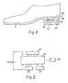
- Figure 1 is a side elevational view of a shoe embodying the invention, and
- Figure 2 is a block diagram of the pedometer incorporated in the embodiment of Figure 1.
- Referring to Figure 1, a shoe has in conventional manner an upper 1, a sole 2, and a
heel 3. - The heel is provided with a cavity in which is disposed electronic counting and processing circuitry, (preferably comprised in an integrated circuit or microchip (30, Figure 1), for example in the form of a microprocessor), powered by a battery 32 (e.g. also incorporated in the heel of the boot or shoe) and connected with an impulse or
shock transducer 34, for example incorporating a piezo electric element, timing means 36, for example incorporating, in manner known per se, a quartz crystal oscillator, also being connected with said circuitry and powered by the battery, the electronic counting and processing circuitry being also connected with anelectronic display element 40 such as a LED or LCD display, and with one ormore control elements 22 such as push-buttons, knobs etc. for purposes of adjustment and mode selection, as set out below. - The display is visible through a transparent window 20 (see Figure 1), provided in the external peripheral surface of the
heel 3, preferably, as shown, in the lateral surface of theheel 3, which is on the inner side of the shoe, i.e. on the side which faces towards the other shoe when worn, (so that the shoe shown in Figure 1 is a right shoe). Resetting means, such as a push-button 22, also disposed on the pripheral surface of theheel 3 may be provided for resetting the counter. - Whilst the electrical current requirement of the timing means and electronic counting and processing circuitry is preferably very low, so that it would be possible to maintain long intervals between battery replacement even if the circuitry were kept energised continuously, for purposes of energy conservation, it is preferable for the arrangement to be such that when the boot or shoe is not in use, at least some of the circuitry is effectively disconnected from the battery. In this case the arrangement may be such that when the boot or shoe is subjected to a shock or impulse, the electrical signal produced by the impulse transducer operates electronic switching means whereby the electronic counting and processing circuitry as a whole, and the timing means or the previously "disconnected" parts of the circuitry are energised from the battery and thereafter remain so energised provided that the time elapsed since the last impulse sensed by the impulse transducer is not greater than a predetermined value as set by the timing means. Such an arrangement is hereafter referred to as an automatic switch on/switch off arrangement.
- The electronic counting and processing circuitry includes counters and dividers etc. associated with the timing means in a manner known per se from electronic watches and the like, and the arrangement is such that timing means, in conjunction with the counting and processing circuitry and the display may, in one operating mode selected by the user by operation of the control means, be operated as a stop watch, whilst in another operating mode it may operate as a normal chronometer or clock (in which case, of course, it is necessary that the timing means and at least part of the circuitry should be energised continuously).
- The electronic counting and processing circuitry preferably incorporates automatic resetting means which, in at least one selected mode of operation, resets at least some of the counters incorporated in the circuitry upon receipt of the first impulse from the impulse and shock transducer following a period greater than a predetermined period (which is preferably nevertheless substantially shorter than that determining operation of the automatic switch on/switch off arrangement), during which no impulses have been detected, so that the number of paces made and/or the time elapsed, since a period of running commenced can be recorded automatically. Similarly, the timing means in conjunction with the electronic counting and processing circuitry may be arranged to register the time elapsed at the instant of the last detected impulse by the transducer so that, in effect, the "stop watch" can be stopped by the wearer simply by the latter remaining stationary for a period. If desired, operation of a manual control element such as a push button on the side of the heel, may be required to displace from memory the time recorded after such a pause. Alternatively, the arrangement may be such that, after such a pause, upon the wearer starting to run again, i.e. upon the receipt of the next impulse from the transducer, the time previously recorded is transferred to another memory location so that whilst, at the end of the next period of running, the time for that period of running is displayed, the time for the previous period of running can be recalled by operation of a manual control.
- The electronic counting and processing circuitry is preferably arranged to calculate, from the signals from the impulse transducer and the timing means and from a constant, corresponding to the wearer's length of pace, stored in the electronic counting and processing circuitry, the speed of the wearer. The value of this constant may be set previously by the wearer, the information being entered, for example, by operation of a push button, for example in much the same way as that in which known digital electronic watches are set, or by rotation of a knob or the like.
- The processing means may be arranged to calculate, for example, average speed over a period of running or peak speed and to display the respective speed in miles per hour or kilometres per hour at choice, (made by operation of the control elements). The processing means, in conjunction with the timing means and impulse transducer, may be arranged to calculate other quantities, such as time spent walking over a larger predetermined time, e.g. over one day, total distance travelled, preferably displayable optionally in miles or kilometres, or the like. It will be appreciated, of course, that preferably the various functions such as time recordal, counting of paces, speed calculation etc. proceed simultaneously so that at any time the relevant data can be displayed in the display unit simply by operation of the control means appropriately.
- Various memory storage locations may be provided in the processing means for other data, such as the number of steps made or distance covered in a previous period or the time elapsed, average speed, peak speed, etc. pertaining to a previous period of exercise, and any item of data selected from these may be caused to be displayed by the display by appropriate operation of the control element or elements.
- Where the circuitry is normally arranged to carry out certain actions, such as automatic switch on/switch off, or automatic stop watch start/stop, preferably manually operable override controls are provided so that these functions may be placed under specific manual control.
- It will be appreciated that, as for the case where a normal clock or chronometer function is to be provided, where it is desired to retain data in memory locations in the circuitry, it may be desirable to secure continuous electrical energisation of at least the respective parts of the circuitry.
- However, where such functions are not required, the automatic switch on/switch off arrangement may apply to substantially the whole of the circuitry. Alternatively, of course, or in addition, a manually operable switch may be provided for control of circuit energisation.
- It will be appreciated that many variants of the invention are possible. Thus, for example, the transducer may be actuated by movement of the wearer's foot relative to the heel of the shoe, or by movement, by engagement with the ground surface, of a part of the heel adapted to engage the ground surface, or a distinct element, relative to the remainder of the shoe.
- Furthermore, the transducer may be arranged to respond to inertial or gravitational forces, such as changes in movement of direction occurring during walking, or changes in the angle of the shoe relative to the horizontal.
- The transducer may also take the form of a microswitch arranged to pass an impulse to the
counter 30 every time a step is taken, or a pressure sensitive electronic transducer, for example utilising a piezo electric element or a strain gauge might be utilised. The switch or pressure sensitive element may be activated by the pressure of the wearer's heel against the sole of the shoe. Alternatively an inertially or gravitationally operated electrical device, such as a mercury switch might be used. The use of an electrical or electronic arrangement has, interalia, the advantage that the sensing element, if sufficiently small, may be placed in the sole of the shoe and connected by wires to the circuitry disposed in the cavity in the heel. - If desired, of course, since only alternate paces or steps will be made, by the wearer, with the foot wearing the shoe, the counter may be arranged to advance the count by two for every depression of the button 11.
- A boot or shoe as described, besides having a considerable novelty appeal for children and adults, for example enabling a child to readily count the number of steps taken in a certain exercise or game, is also of utility for athletes or other persons undertaking a programme of exercise to improve or enhance physical fitness and which involves the counting of steps taken. Thus, a shoe for joggers may usefully incorporate a counter or pedometer as described above. A boot or shoe as described may also be used in the measurement of distance by pacing out, relying on a predetermined average length of step.
- Furthermore, in a pedometer incorporating a micro-processor as proposed, further inputs to the micro-processor may be supplied by devices arranged, for example to sense the wearer's pulse rate, blood pressure etc., with the micro-processor being arranged to correlate these quantities with the exercise taken, and such a device may clearly have important medical applications.
Claims (11)
Priority Applications (1)
| Application Number | Priority Date | Filing Date | Title |
|---|---|---|---|
| AT82901136T ATE14508T1 (en) | 1981-04-25 | 1982-04-23 | BOOT OR SHOE WITH A PEDOMETER O.AE. |
Applications Claiming Priority (6)
| Application Number | Priority Date | Filing Date | Title |
|---|---|---|---|
| GB8112807 | 1981-04-25 | ||
| GB8112807 | 1981-04-25 | ||
| GB8129212 | 1981-09-28 | ||
| GB8129212 | 1981-09-28 | ||
| GB8210351 | 1982-04-07 | ||
| GB8210351 | 1982-04-07 |
Publications (2)
| Publication Number | Publication Date |
|---|---|
| EP0089340A1 EP0089340A1 (en) | 1983-09-28 |
| EP0089340B1 true EP0089340B1 (en) | 1985-07-31 |
Family
ID=27261165
Family Applications (1)
| Application Number | Title | Priority Date | Filing Date |
|---|---|---|---|
| EP82901136A Expired EP0089340B1 (en) | 1981-04-25 | 1982-04-23 | Boot or shoe incorporating pedometer or the like |
Country Status (9)
| Country | Link |
|---|---|
| US (1) | US4510704A (en) |
| EP (1) | EP0089340B1 (en) |
| JP (1) | JPS58500595A (en) |
| AU (1) | AU556183B2 (en) |
| BR (1) | BR8207884A (en) |
| DE (1) | DE3265038D1 (en) |
| FI (1) | FI71471C (en) |
| NO (1) | NO153751C (en) |
| WO (1) | WO1982003753A1 (en) |
Families Citing this family (96)
| Publication number | Priority date | Publication date | Assignee | Title |
|---|---|---|---|---|
| US4578769A (en) * | 1983-02-09 | 1986-03-25 | Nike, Inc. | Device for determining the speed, distance traversed, elapsed time and calories expended by a person while running |
| FR2553547A1 (en) * | 1983-10-12 | 1985-04-19 | Malucelli Joel | Distance counter for pedestrians |
| JPS60200120A (en) * | 1984-03-24 | 1985-10-09 | Matsushita Electric Works Ltd | Pedometer |
| US4649552A (en) * | 1984-03-19 | 1987-03-10 | Matsushita Electric Works, Ltd. | Electronic pedometer with step sensor in removable insole |
| FR2571941B1 (en) * | 1984-10-24 | 1987-06-26 | Malucelli Joel | REMOVABLE SOLE FOR FOOTWEAR |
| US5033013A (en) * | 1985-04-22 | 1991-07-16 | Yamasa Tokei Meter Co., Ltd. | Method and apparatus for measuring the amount of exercise |
| US4814661A (en) * | 1986-05-23 | 1989-03-21 | Washington State University Research Foundation, Inc. | Systems for measurement and analysis of forces exerted during human locomotion |
| US4845863A (en) * | 1987-02-20 | 1989-07-11 | Autry Industries, Inc. | Shoe having transparent window for viewing cushion elements |
| US4843741A (en) * | 1987-02-20 | 1989-07-04 | Autry Industries, Inc. | Custom insert with a reinforced heel portion |
| CA1270306A (en) * | 1987-08-07 | 1990-06-12 | Dennis Furlong | Electronic monitoring of ground contact by an athlete's shoes |
| US4962469A (en) * | 1988-04-18 | 1990-10-09 | Casio Computer Co., Ltd. | Exercise measuring instrument |
| EP0359699B1 (en) * | 1988-09-16 | 1994-05-04 | Autry Industries, Inc | Shoe having transparent window for viewing cushion elements |
| US4891797A (en) * | 1989-03-29 | 1990-01-02 | Joselean Woodfalks | Running shoe with integral timer |
| US5500635A (en) * | 1990-02-20 | 1996-03-19 | Mott; Jonathan C. | Products incorporating piezoelectric material |
| US5269081A (en) * | 1992-05-01 | 1993-12-14 | Gray Frank B | Force monitoring shoe |
| US5471405A (en) * | 1992-11-13 | 1995-11-28 | Marsh; Stephen A. | Apparatus for measurement of forces and pressures applied to a garment |
| US5373651A (en) * | 1993-05-03 | 1994-12-20 | Wood; Thomas L. | Smart shoes |
| US5343445A (en) * | 1993-07-06 | 1994-08-30 | David Stern | Athletic shoe with timing device |
| AU5435094A (en) * | 1993-08-26 | 1995-03-21 | Ionel Marin Olteanu | Footwear with electronic device |
| GB2282521A (en) * | 1993-10-08 | 1995-04-12 | Alireza Madjdnia | Sport shoes |
| GB2285735B (en) * | 1994-01-06 | 1997-06-11 | Chiang Jiin Huei | Footstep-counting device |
| US6539336B1 (en) * | 1996-12-12 | 2003-03-25 | Phatrat Technologies, Inc. | Sport monitoring system for determining airtime, speed, power absorbed and other factors such as drop distance |
| US7739076B1 (en) | 1999-06-30 | 2010-06-15 | Nike, Inc. | Event and sport performance methods and systems |
| US7386401B2 (en) * | 1994-11-21 | 2008-06-10 | Phatrat Technology, Llc | Helmet that reports impact information, and associated methods |
| US7949488B2 (en) * | 1994-11-21 | 2011-05-24 | Nike, Inc. | Movement monitoring systems and associated methods |
| US5680718A (en) * | 1994-12-20 | 1997-10-28 | First Choice Trading Limited | Illuminable hat |
| US5592759A (en) * | 1995-01-26 | 1997-01-14 | Co-Jo Sports, Inc. | Vibrating footwear |
| FR2733839B1 (en) * | 1995-05-02 | 1997-07-18 | Lipha | METHOD AND DEVICE FOR MEASURING CHARACTERISTIC DATA OF THE MOVEMENT OF A PEDESTRIAN |
| US5640786A (en) * | 1995-07-05 | 1997-06-24 | Buyayez; Taher | Monitored footwear with step counter and speedometer display |
| US5697308A (en) * | 1995-12-20 | 1997-12-16 | Kennametal Inc. | Seed boot having a wear resistant insert |
| US5661916A (en) * | 1996-07-05 | 1997-09-02 | Huang; Tien-Tsai | Electronic step counting shoe |
| US6012822A (en) * | 1996-11-26 | 2000-01-11 | Robinson; William J. | Motion activated apparel flasher |
| CA2199458C (en) * | 1997-03-07 | 2000-06-27 | Tien-Tsai Huang | Electronic step counting shoe |
| US5797201A (en) * | 1997-07-24 | 1998-08-25 | Huang; Tien-Tsai | Shoe with step counting capability |
| US6898550B1 (en) | 1997-10-02 | 2005-05-24 | Fitsense Technology, Inc. | Monitoring activity of a user in locomotion on foot |
| US6560903B1 (en) | 2000-03-07 | 2003-05-13 | Personal Electronic Devices, Inc. | Ambulatory foot pod |
| US6122340A (en) * | 1998-10-01 | 2000-09-19 | Personal Electronic Devices, Inc. | Detachable foot mount for electronic device |
| US5945911A (en) * | 1998-03-13 | 1999-08-31 | Converse Inc. | Footwear with multilevel activity meter |
| US6175608B1 (en) | 1998-10-28 | 2001-01-16 | Knowmo Llc | Pedometer |
| US6473483B2 (en) | 1998-10-28 | 2002-10-29 | Nathan Pyles | Pedometer |
| AU6065600A (en) * | 1999-06-30 | 2001-01-31 | Phatrat Technology, Inc. | Event and sport performance methods and systems |
| GB2353937A (en) * | 1999-08-27 | 2001-03-14 | Ian Anthony Liston | Footwear having monitoring device and display |
| US6273863B1 (en) | 1999-10-26 | 2001-08-14 | Andante Medical Devices, Ltd. | Adaptive weight bearing monitoring system for rehabilitation of injuries to the lower extremities |
| US6438872B1 (en) * | 1999-11-12 | 2002-08-27 | Harry Miller Co., Inc. | Expandable shoe and shoe assemblies |
| US6807754B2 (en) * | 1999-11-12 | 2004-10-26 | Inchworm, Inc. | Expandable shoe and shoe assemblies |
| US7581337B2 (en) * | 1999-11-12 | 2009-09-01 | Inchworm, Inc. | Expandable shoe having screw drive assemblies |
| US6574888B2 (en) * | 1999-11-12 | 2003-06-10 | Harry Miller Company, Inc. | Expandable shoe and shoe assemblies |
| US8956228B2 (en) * | 1999-12-03 | 2015-02-17 | Nike, Inc. | Game pod |
| US6585622B1 (en) * | 1999-12-03 | 2003-07-01 | Nike, Inc. | Interactive use an athletic performance monitoring and reward method, system, and computer program product |
| AU2410901A (en) * | 2000-01-03 | 2001-07-16 | Alfredo Morfin Lopez | Universal electronic impact counter or impactometer |
| US6578291B2 (en) * | 2000-06-06 | 2003-06-17 | John Hirsch | Shoe wear indicator |
| KR200216691Y1 (en) * | 2000-10-10 | 2001-03-15 | 송문호 | Adhesion on foot counter device of shoes |
| KR200216707Y1 (en) * | 2000-10-27 | 2001-03-15 | 송문호 | Adhesion on foot counter device of shoes |
| US6805006B2 (en) | 2000-12-07 | 2004-10-19 | Bbc International, Ltd. | Method and apparatus for measuring the maximum speed of a runner over a prescribed distance including a transmitter and receiver |
| US6604419B2 (en) * | 2000-12-07 | 2003-08-12 | Bbc International, Ltd. | Apparatus and method for measuring the maximum speed of a runner over a prescribed distance |
| AU2002255568B8 (en) | 2001-02-20 | 2014-01-09 | Adidas Ag | Modular personal network systems and methods |
| AU2003288938A1 (en) | 2002-10-30 | 2004-06-07 | Nike International Ltd. | Clothes with tracking marks for computer games |
| US8206219B2 (en) | 2002-10-30 | 2012-06-26 | Nike, Inc. | Interactive gaming apparel for interactive gaming |
| US20040140348A1 (en) * | 2003-01-16 | 2004-07-22 | Fromm Wayne G. | Pedometer |
| AU2004230678A1 (en) | 2003-04-03 | 2004-10-28 | University Of Virginia Patent Foundation | Method and system for the derivation of human gait characteristics and detecting falls passively from floor vibrations |
| DE10325805B4 (en) * | 2003-06-06 | 2005-12-01 | Siemens Ag | Sports shoe with indication of wear and / or the use of its damping |
| DE10362030B4 (en) * | 2003-06-06 | 2006-01-19 | Siemens Ag | Sports shoe, has medium for displaying wastage and/or utilization of medium for damping of shoe, and medium adding piezoelectric effect over diode array, which is sequentially destructible by adding piezoelectric effect |
| US7287294B2 (en) * | 2003-10-24 | 2007-10-30 | Harry Miller Co., Inc. | Method of making an expandable shoe |
| US7059070B2 (en) * | 2003-10-31 | 2006-06-13 | Alina Designs, Inc. | Footwear containing improved audio/visual displays |
| JP2005267152A (en) * | 2004-03-18 | 2005-09-29 | Seiko Instruments Inc | Electronic pedometer |
| US20060230640A1 (en) * | 2004-10-07 | 2006-10-19 | Chen Hsin N | Shoe having physical measuring device |
| US7299034B2 (en) * | 2005-06-21 | 2007-11-20 | Lawrence Kates | System and method for wearable electronics |
| US8028443B2 (en) * | 2005-06-27 | 2011-10-04 | Nike, Inc. | Systems for activating and/or authenticating electronic devices for operation with footwear |
| WO2007016584A2 (en) * | 2005-08-01 | 2007-02-08 | Merkel Carolyn M | Wearable fitness device and fitness device interchangeable with plural wearable articles |
| US20060066056A1 (en) * | 2005-09-27 | 2006-03-30 | Wiblin Brian D | Device to count strikes |
| US20090278707A1 (en) * | 2006-04-13 | 2009-11-12 | Sential, Llc | Wear monitor for recreational footgear |
| EP2019601A1 (en) * | 2006-05-03 | 2009-02-04 | Ashton Walter Bishop | Footwear with colour indicating means to indicate a variety of conditions |
| US7607243B2 (en) | 2006-05-03 | 2009-10-27 | Nike, Inc. | Athletic or other performance sensing systems |
| KR100702613B1 (en) * | 2006-05-30 | 2007-04-03 | 주식회사 아이손 | Artificial intelligence shoe mounting a controller and method for measuring quantity of motion |
| JP4885637B2 (en) * | 2006-07-27 | 2012-02-29 | セイコーインスツル株式会社 | Arm-mounted electronic pedometer |
| US8439816B2 (en) * | 2009-07-14 | 2013-05-14 | Pulse, Llc | Piezoelectric, micro-exercise apparatus and method |
| IL180833A (en) * | 2007-01-21 | 2012-10-31 | Israel Aerospace Ind Ltd | Pedestrian navigation system and method |
| US20080254944A1 (en) * | 2007-04-14 | 2008-10-16 | Muri John I | Monitoring of a Wearable Athletic Device |
| US7854077B1 (en) | 2007-05-24 | 2010-12-21 | Mario I Jauregui | Shoe having configurable message board |
| US20100255968A1 (en) * | 2009-04-07 | 2010-10-07 | Jiang rong-hua | Sit-Up Exercising Apparatus |
| US11191975B2 (en) | 2009-07-14 | 2021-12-07 | Pulse, Llc | Micro-coil wristband |
| US9498639B2 (en) | 2014-05-13 | 2016-11-22 | Pulse, Llc | Immersive, flux-guided, micro-coil apparatus and method |
| US10507333B2 (en) | 2009-07-14 | 2019-12-17 | Pulse, Llc | Immersive, flux-guided, micro-coil apparatus and method |
| US11878181B2 (en) | 2009-07-14 | 2024-01-23 | Pulse, Llc | Micro-coil wristband |
| US10363453B2 (en) | 2011-02-07 | 2019-07-30 | New Balance Athletics, Inc. | Systems and methods for monitoring athletic and physiological performance |
| KR102009711B1 (en) | 2011-02-07 | 2019-08-12 | 뉴우바란스아스레틱스인코포레이팃드 | Systems and methods for monitoring athletic performance |
| US10102345B2 (en) * | 2012-06-19 | 2018-10-16 | Activbody, Inc. | Personal wellness management platform |
| ITTO20120833A1 (en) * | 2012-09-26 | 2014-03-27 | St Microelectronics Srl | COUNTERPASS DEVICE EQUIPPED WITH FUNCTIONALITY OF ENERGY COLLECTION AND METHOD OF COUNTING STEPS |
| WO2015002827A1 (en) * | 2013-07-01 | 2015-01-08 | BUDDIES, Step | System, apparatus, and method for measuring number of user steps |
| CN103960823A (en) * | 2014-04-16 | 2014-08-06 | 盐城工业职业技术学院 | Shoe sole step counter |
| USD763453S1 (en) | 2014-05-13 | 2016-08-09 | Pulse, Llc | Micro-coil array |
| USD762864S1 (en) | 2014-05-13 | 2016-08-02 | Pulse, Llc | Micro-coil array |
| US9055778B1 (en) * | 2014-08-28 | 2015-06-16 | Skechers U.S.A., Inc. Ii | Article of footwear with interactive system |
| US11047706B2 (en) * | 2016-02-01 | 2021-06-29 | One Two Free Inc. | Pedometer with accelerometer and foot motion distinguishing method |
| US20180146737A1 (en) * | 2016-04-28 | 2018-05-31 | Joseph Goodrich | Shoe system for the detection and monitoring of health, vitals, and fall detection |
| TWM530059U (en) * | 2016-05-10 | 2016-10-11 | Homeway Technology Co Ltd | Wearable pedometer shoes |
Family Cites Families (8)
| Publication number | Priority date | Publication date | Assignee | Title |
|---|---|---|---|---|
| US542107A (en) * | 1895-07-02 | Hungary | ||
| CH4438A (en) * | 1891-12-19 | 1892-05-14 | Johann Homola | Pedometer |
| US4019030A (en) * | 1975-11-03 | 1977-04-19 | Tamiz Farouq M | Step-counting shoe |
| US4175446A (en) * | 1978-04-26 | 1979-11-27 | The University Of Iowa Research Foundation | Step counting device and method |
| US4220996A (en) * | 1979-01-31 | 1980-09-02 | Searcy Talmadge R | Jogger's computational device |
| US4371945A (en) * | 1980-12-01 | 1983-02-01 | Lawrence Joseph Karr | Electronic pedometer |
| US4402147A (en) * | 1981-05-27 | 1983-09-06 | Chyuan Jong Wu | Shoe having automatic step counter |
| US4466204A (en) * | 1981-05-27 | 1984-08-21 | Chyuan Jong Wu | Electronic pace and distance counting shoe |
-
1982
- 1982-04-23 US US06/451,166 patent/US4510704A/en not_active Expired - Fee Related
- 1982-04-23 JP JP57501265A patent/JPS58500595A/en active Pending
- 1982-04-23 BR BR8207884A patent/BR8207884A/en unknown
- 1982-04-23 EP EP82901136A patent/EP0089340B1/en not_active Expired
- 1982-04-23 WO PCT/GB1982/000119 patent/WO1982003753A1/en not_active Application Discontinuation
- 1982-04-23 AU AU83355/82A patent/AU556183B2/en not_active Ceased
- 1982-04-23 DE DE8282901136T patent/DE3265038D1/en not_active Expired
- 1982-12-23 NO NO824349A patent/NO153751C/en unknown
-
1983
- 1983-05-25 FI FI831867A patent/FI71471C/en not_active IP Right Cessation
Also Published As
| Publication number | Publication date |
|---|---|
| NO153751C (en) | 1986-05-21 |
| FI831867A0 (en) | 1983-05-25 |
| BR8207884A (en) | 1983-08-30 |
| AU556183B2 (en) | 1986-10-23 |
| JPS58500595A (en) | 1983-04-21 |
| NO824349L (en) | 1982-12-23 |
| WO1982003753A1 (en) | 1982-11-11 |
| FI831867L (en) | 1983-05-25 |
| FI71471C (en) | 1987-01-19 |
| FI71471B (en) | 1986-10-10 |
| DE3265038D1 (en) | 1985-09-05 |
| US4510704A (en) | 1985-04-16 |
| NO153751B (en) | 1986-02-10 |
| AU8335582A (en) | 1982-11-24 |
| EP0089340A1 (en) | 1983-09-28 |
Similar Documents
| Publication | Publication Date | Title |
|---|---|---|
| EP0089340B1 (en) | Boot or shoe incorporating pedometer or the like | |
| US5720200A (en) | Performance measuring footwear | |
| US4220996A (en) | Jogger's computational device | |
| US10824118B2 (en) | Athletic watch | |
| US6604419B2 (en) | Apparatus and method for measuring the maximum speed of a runner over a prescribed distance | |
| US9329053B2 (en) | Athletic watch | |
| JP6282611B2 (en) | Exercise clock | |
| US5452269A (en) | Athletic shoe with timing device | |
| US4409992A (en) | Electronic ergometer | |
| EP1266190B1 (en) | An exercise monitoring apparatus | |
| EP0060361A1 (en) | Runners watch | |
| WO1988004768A1 (en) | Improvements in or relating to pedometers and the like | |
| WO2008023978A1 (en) | System for measuring weight loss, a force sensor pad, a shoe and a portable monitoring device | |
| US6805006B2 (en) | Method and apparatus for measuring the maximum speed of a runner over a prescribed distance including a transmitter and receiver | |
| US4891797A (en) | Running shoe with integral timer | |
| US6738726B2 (en) | Apparatus and method for measuring the maximum speed of a runner over a prescribed distance | |
| CA1183111A (en) | Boot or shoe incorporating pedometer or the like | |
| GB2176036A (en) | Counting device for use by swimmers | |
| US6614726B2 (en) | Stopwatch | |
| JPH0821070B2 (en) | Electronic pedometer | |
| JPS5952391A (en) | Electronic pedometer | |
| WO2002030238A1 (en) | The walking counter device to be installed in the shoe |
Legal Events
| Date | Code | Title | Description |
|---|---|---|---|
| PUAI | Public reference made under article 153(3) epc to a published international application that has entered the european phase |
Free format text: ORIGINAL CODE: 0009012 |
|
| 17P | Request for examination filed |
Effective date: 19830518 |
|
| AK | Designated contracting states |
Designated state(s): AT BE CH DE FR GB LI LU NL SE |
|
| GRAA | (expected) grant |
Free format text: ORIGINAL CODE: 0009210 |
|
| AK | Designated contracting states |
Designated state(s): AT BE CH DE FR GB LI LU NL SE |
|
| REF | Corresponds to: |
Ref document number: 14508 Country of ref document: AT Date of ref document: 19850815 Kind code of ref document: T |
|
| REF | Corresponds to: |
Ref document number: 3265038 Country of ref document: DE Date of ref document: 19850905 |
|
| ET | Fr: translation filed | ||
| PGFP | Annual fee paid to national office [announced via postgrant information from national office to epo] |
Ref country code: AT Payment date: 19860421 Year of fee payment: 5 |
|
| PG25 | Lapsed in a contracting state [announced via postgrant information from national office to epo] |
Ref country code: LU Free format text: LAPSE BECAUSE OF NON-PAYMENT OF DUE FEES Effective date: 19860430 |
|
| PLBI | Opposition filed |
Free format text: ORIGINAL CODE: 0009260 |
|
| 26 | Opposition filed |
Opponent name: PUMA-SPORTSCHUHFABRIKEN RUDOLF DASSLER KG Effective date: 19860429 |
|
| NLR1 | Nl: opposition has been filed with the epo |
Opponent name: PUMA-SPORTSCHUHFABRIKEN RUDOLF DASSLER KG |
|
| PGFP | Annual fee paid to national office [announced via postgrant information from national office to epo] |
Ref country code: NL Payment date: 19870430 Year of fee payment: 6 |
|
| PG25 | Lapsed in a contracting state [announced via postgrant information from national office to epo] |
Ref country code: GB Effective date: 19880423 Ref country code: AT Effective date: 19880423 |
|
| PG25 | Lapsed in a contracting state [announced via postgrant information from national office to epo] |
Ref country code: SE Effective date: 19880424 |
|
| BERE | Be: lapsed |
Owner name: JOHNSON WILLIAM NEVIL HEATON Effective date: 19880430 |
|
| PG25 | Lapsed in a contracting state [announced via postgrant information from national office to epo] |
Ref country code: NL Effective date: 19881101 |
|
| NLV4 | Nl: lapsed or anulled due to non-payment of the annual fee | ||
| GBPC | Gb: european patent ceased through non-payment of renewal fee | ||
| REG | Reference to a national code |
Ref country code: CH Ref legal event code: PL |
|
| RDAG | Patent revoked |
Free format text: ORIGINAL CODE: 0009271 |
|
| STAA | Information on the status of an ep patent application or granted ep patent |
Free format text: STATUS: PATENT REVOKED |
|
| REG | Reference to a national code |
Ref country code: FR Ref legal event code: ST |
|
| GBPR | Gb: patent revoked under art. 102 of the ep convention designating the uk as contracting state | ||
| 27W | Patent revoked |
Effective date: 19881124 |
|
| EUG | Se: european patent has lapsed |
Ref document number: 82901136.0 Effective date: 19890726 |