EP0077568A2 - Circuit-breaker with actuation which can be programmed - Google Patents
Circuit-breaker with actuation which can be programmed Download PDFInfo
- Publication number
- EP0077568A2 EP0077568A2 EP82109649A EP82109649A EP0077568A2 EP 0077568 A2 EP0077568 A2 EP 0077568A2 EP 82109649 A EP82109649 A EP 82109649A EP 82109649 A EP82109649 A EP 82109649A EP 0077568 A2 EP0077568 A2 EP 0077568A2
- Authority
- EP
- European Patent Office
- Prior art keywords
- circuit breaker
- module
- breaker according
- circuit
- metallic element
- Prior art date
- Legal status (The legal status is an assumption and is not a legal conclusion. Google has not performed a legal analysis and makes no representation as to the accuracy of the status listed.)
- Withdrawn
Links
Images
Classifications
-
- H—ELECTRICITY
- H01—ELECTRIC ELEMENTS
- H01H—ELECTRIC SWITCHES; RELAYS; SELECTORS; EMERGENCY PROTECTIVE DEVICES
- H01H83/00—Protective switches, e.g. circuit-breaking switches, or protective relays operated by abnormal electrical conditions otherwise than solely by excess current
- H01H83/20—Protective switches, e.g. circuit-breaking switches, or protective relays operated by abnormal electrical conditions otherwise than solely by excess current operated by excess current as well as by some other abnormal electrical condition
- H01H2083/206—Protective switches, e.g. circuit-breaking switches, or protective relays operated by abnormal electrical conditions otherwise than solely by excess current operated by excess current as well as by some other abnormal electrical condition with thermal shunt trip
Definitions
- the present invention relates to the improvement of an electrical circuit breaker module of known type, incorporating a conventional circuit breaker.
- the improvement consists in inserting into the module a controlled switch for triggering or engaging the bypass circuit associated with the module.
- This controlled switch is housed in the module without having to make any modification whatsoever to its thickness (height of the front wall), along the vertical plane, as well as to its depth.
- the utility value of an electric circuit breaker module inside a connection box is obvious and this value is increased when the module includes an additional controlled switch used to engage or trigger the electrical bypass circuit with which it is associated.
- the activation of the controlled switch can be controlled remotely from the connection box so as to activate it when necessary or using programmable or non-programmable control automations. This then results in a control of each electrical branch circuit of a connection box or of those which it is thus desired to control so as to control the supply of the electrical charges connected to each of the circuits.
- Another important advantage inherent in this improved circuit breaker module is that the user has the ability to automatically control a variety of electrical branch circuits.
- timer devices or other programmable devices it is possible to control the switching on or off of lighting or other electrical devices at predetermined times of the day when the premises are unoccupied or during periods vacation. Such an operation of electrical devices would then simulate an occupation of the premises.
- Another advantage of this type of electrical circuit breaker module lies in the ability to manage the distribution of loads, which leads to energy conservation with regard in particular: the electric heating systems which can be programmed for n '' be operated only at predetermined times and / or in response to changes in temperature.
- Another characteristic resides in a controlled switch element which is small enough to be incorporated into a circuit breaker module and which requires a relatively low power supply for its operation with a view to switching on and off electrical branch circuits of 110 or 220 volts or other similar low voltage branch circuits below 600 volts.
- a characteristic of the present invention resides in the production of an improved electrical circuit breaker module which meets the needs stated above and which is substantially free from all the disadvantages of the device of the prior art mentioned above.
- Another characteristic of the present invention consists of an electric circuit breaker module which incorporates a conventional circuit breaker and a switch device controlled inside the same module without modifying the thickness of the module, along a vertical plane.
- Another characteristic of the present invention is to provide an improved circuit breaker module which has a controlled switch device, the control of which is carried out from a place remote from a connection box and / or automatically by the user or a scheduling device.
- Another characteristic of the present invention resides in an improved electrical circuit breaker module which has a conventional circuit breaker and a switching device: controlled and which can adapt to an existing connection box which incorporates a plurality of conventional electrical circuit breaker modules without it it is necessary to - move the already wired existing modules.
- Another characteristic of the present invention resides in the production of an improved electric circuit breaker module comprising a conventional circuit breaker and a controlled switch device and which is relatively inexpensive to manufacture and install.
- the present invention relates to an improvement of an electrical circuit breaker module, plug-in, of small size, and which is mounted superimposed in columns by stacking on a plurality of modules at the inside of an electrical connection box.
- Each of the modules is respectively connected to electrical branch circuits and is provided with circuit interruption means for disconnecting the branch circuit with which it is associated at the time of an overcurrent or a fault on the branch circuit.
- the improvement includes a controlled switch means mounted in at least one of the modules, without modifying the thickness of the module, according to a vertical plane, and its depth. This controlled switch means is connected in series by means of a circuit switch and is put into operation using an external or internal control means of the module which governs the open or closed state of the contacts.
- the electrical circuit breaker module of the present invention is generally designated by the reference 10.
- the module consists of a conventional enclosure formed of an insulating material and houses a switch mechanical 16 coupled to an overcurrent protection element 12 (see Figure 4).
- circuit breaker modules 10 are usually fixed to a connection box by stacking one on the other.
- Each module may include one or more marking connections 13 and one or more electrical connections 14 so as to connect a module to a particular electrical branch circuit among the plurality of circuits entering and leaving the connection box, as is well known in art.
- the modules can also be of the type which can incorporate fusible elements of the screw or cartridge type. tubular which can be fixed in a removable way on the front of the module.
- These modules are of different construction from those illustrated in Figures 1 and 2 but are similarly stacked on top of each other and / or side by side.
- the present invention relates to an improvement of such a circuit breaker module in which a controlled switch element 15 is inserted inside this same module 10 without having to modify the thickness of the module taken along the vertical plane. As illustrated in Figure 4, this switch element 1.5 is connected in series with the circuit breaker element 12. As shown in Figure 2, the circuit breaker module is provided with a manual control button 16 allowing the circuit breaker to occupy the position "ON” or "OFF".
- the controlled switch device 15 it is operated remotely, relative to the connection box and can be activated using an electrical signal, in this case a low power source connected to socket 18 enabling the switch element 15 to be activated or deactivated.
- the command may be produced by the user himself and / or the operating company which owns the energy transport network. It is also conceivable the possibility of controlling the switch element 15 according to an established schedule so as to engage and trip the electrical circuit coupled to the circuit breaker module 10 at hours and according to predetermined conditions during the day so as to control various electrical devices connected to the branch circuits.
- the switch element 15 may consist of an electronic switch or other means. All that is actually required is that the switch is of relatively small size and is capable of operating at very low power and that it is further able to engage and trip branch circuits operating at voltages of 110 or 220 Volts for example, which correspond to the voltages usually used at the residential and commercial level.
- the switching element 15 consists of a thermo-mechanical switch comprising an actuating element formed of a bi-metallic disc 19, sensitive to temperature, on which is fixed a heating conductive element 20 capable of causing deformation of the disc when it is heated.
- the disc is of concave / convex construction and formed of a bi-metallic material so that the heating of the disc causes it to expand and move from its normal position to another position designated by 19 'in Figure 5.
- the disc 19 is held by means of a rigid side wall 26 which allows the deflection of the disc in the position 19 '.
- a rigid rod 17 connects the lower surface 21 of the disc 19 to the arm 22 of the switch so that when the disc is heated and occupies the position shown in 19 ', the contact 22 is open (as shown by the dotted lines) opening thus the associated branch circuit 23 connected to the circuit breaker module housing the switch element 15.
- 1e disc 19 has a circular configuration while the filiform heating element 20 is arranged in a serpentine over a large part of the surface of the disc 19.
- the disc 19 can also be formed from a bi-band. rectangular metal.
- the switch is actuated by applying a voltage across terminals A and B of the threadlike heating element.
- the enclosure 24 of the switch is connected in series to line 23 of the branch circuit using the end conductors 25.
- thermo-mechanical disc switch lies in the very low power required for actuation.
- the construction of the disc allows rapid action to interrupt the supply of the electric circuit 23 which can be subjected to a current of 30 amps, for example.
- this switch allows it to be incorporated inside the module housing the conventional circuit breaker and to achieve the various advantages described above.
Landscapes
- Breakers (AREA)
- Thermally Actuated Switches (AREA)
Abstract
L'invention a trait au perfectionnement d'un disjoncteur modulaire de modèle embrochable, que l'on superpose en colonnes à l'intérieur d'un coffret de branchement électrique conventionnel. L'amélioration consiste à ajouter en série, à l'intérieur du boîtier du module (10) du disjoncteur, un dispositif interrupteur contrôlé (15) permettant la mise en ou hors service de son circuit de dérivation. L'addition de ce dispositif laisse intacte l'épaisseur et la hauteur du disjoncteur, rendant ainsi interchangeable le disjoncteur conventionnel et la version perfectionnée. Ce disjoncteur perfectionné est actionné par un dispositif de commande intérieur ou extérieur à son boîtier, selon les besoins.The invention relates to the improvement of a modular circuit breaker of plug-in model, which is superimposed in columns inside a conventional electrical connection box. The improvement consists in adding in series, inside the module housing (10) of the circuit breaker, a controlled switch device (15) allowing the activation or deactivation of its branch circuit. The addition of this device leaves the thickness and height of the circuit breaker intact, thus making the conventional circuit breaker and the improved version interchangeable. This improved circuit breaker is actuated by a control device inside or outside its housing, as required.
Description
La présente invention concerne le perfectionnement d'un module disjoncteur électrique de type connu, incorporant un disjoncteur conventionnel. Le perfectionnement consiste à insérer dans le module un interrupteur contrôlé pour le déclenchement ou l'enclenchement du circuit de dérivation associé au module. Cet interrupteur contrôlé est logé dans le module sans avoir à apporter quelque modification que ce soit à son épaisseur (hauteur de la paroi frontale), suivant le plan vertical, ainsi qu'à sa profondeur.The present invention relates to the improvement of an electrical circuit breaker module of known type, incorporating a conventional circuit breaker. The improvement consists in inserting into the module a controlled switch for triggering or engaging the bypass circuit associated with the module. This controlled switch is housed in the module without having to make any modification whatsoever to its thickness (height of the front wall), along the vertical plane, as well as to its depth.
La valeur utilitaire d'un module disjoncteur électrique à l'intérieur d'un coffret de branchement, où plusieurs modules semblables sont superposés par empilage en colonnes, est évidente et cette valeur est accrue lorsque le module comporte un interrupteur contrôlé additionnel servant à enclencher ou déclencher le circuit de dérivation électrique auquel il est associé. La mise en fonction de l'interrupteur contrôlé peut être commandée à distance du coffret de branchement de sorte à l'actionner lorsque besoin est ou à l'aide d'automatismes de commande programmables ou non. Il en résulte alors un contrôle de chaque circuit de dérivation électrique d'un coffret de branchement ou de ceux que l'on désire ainsi contrôler de sorte à commander l'alimentation des charges électriques reliées à chacun des circuits. Les avantages afférents à cette capacité de commande de l'alimentation de chacun ou de quelques-uns des circuits de dérivation sont nombreux; on note en particulier le fait de pouvoir atténuer la demande d'énergie considérable le long d'une artère de distribution au moment de la reprise en charge, suite à une panne prolongée, afin de minimiser le courant d'appel lors de la remise en service.The utility value of an electric circuit breaker module inside a connection box, where several similar modules are stacked by stacking in columns, is obvious and this value is increased when the module includes an additional controlled switch used to engage or trigger the electrical bypass circuit with which it is associated. The activation of the controlled switch can be controlled remotely from the connection box so as to activate it when necessary or using programmable or non-programmable control automations. This then results in a control of each electrical branch circuit of a connection box or of those which it is thus desired to control so as to control the supply of the electrical charges connected to each of the circuits. The advantages relating to this power control capacity for each or some of the branch circuits are numerous; we note in particular the fact of being able to attenuate the considerable energy demand along a distribution artery at the time of resumption of charge, following a prolonged breakdown, in order to minimize the inrush current during the resumption service.
Un autre avantage important inhérent au présent module disjoncteur amélioré réside dans le fait que l'utilisateur a la possibilité de contrôler automatiquement une gamme variée de circuits de dérivation électriques. Au moyen de dispositifs à minuterie ou d'autres dispositifs programmables on peut commander la mise en ou hors service de l'éclairage ou autres appareils électriques à des heures prédéterminées de la journée lorsque les lieux sont inhabités ou durant les périodes de vacances. Une telle mise en fonctionnement des appareils électriques simulerait alors une occupation des lieux.Another important advantage inherent in this improved circuit breaker module is that the user has the ability to automatically control a variety of electrical branch circuits. By means of timer devices or other programmable devices, it is possible to control the switching on or off of lighting or other electrical devices at predetermined times of the day when the premises are unoccupied or during periods vacation. Such an operation of electrical devices would then simulate an occupation of the premises.
Un autre avantage de ce type de module disjoncteur électrique réside dans la capacité de réaliser une gestion de la distribution des charges, ce qui amène une conservation d'énergie en ce qui regarde en particulier : les systèmes de chauffage électriques qui peuvent être programmés pour n'être mis en fonctionnement qu'à des heures prédéterminées et/ou en réponse à des changements de température.Another advantage of this type of electrical circuit breaker module lies in the ability to manage the distribution of loads, which leads to energy conservation with regard in particular: the electric heating systems which can be programmed for n '' be operated only at predetermined times and / or in response to changes in temperature.
Une autre caractéristique réside dans un élément interrupteur contrôlé qui est suffisamment petit pour être incorporé à un module disjoncteur et qui requiert une alimentation en puissance relativement faible pour son fonctionnement en vue de l'enclenchement et du déclenchement de circuits de dérivation électriques de 110 ou 220 volts ou d'autres circuits de dérivation similaires de basse tension, inférieure à 600 volts.Another characteristic resides in a controlled switch element which is small enough to be incorporated into a circuit breaker module and which requires a relatively low power supply for its operation with a view to switching on and off electrical branch circuits of 110 or 220 volts or other similar low voltage branch circuits below 600 volts.
Mentionnons ici l'existence du brevet des Etats-Unis n° 4 164 719 qui décrit un appareil de gestion des charges et dont la mise en opération par l'utilisateur est indépendante de tout contrôle, cet appareil servant à enclencher certains circuits de dérivation électriques choisis. La fonction du dispositif breveté est de couper des circuits de dérivation choisis et en particulier les circuits de dérivation de caractère qui sont non critiques. Un désavantage du dispositif proposé est qu'il requiert un second module interrupteur pour le logement d'un interrupteur commandé à distance, en ce cas-ci un relais. Cela nécessite un réarrangement complet du coffret de branchement si l'on veut qu'un ou deux des circuits de dérivation soient adaptés à ce module additionnel. De plus, l'agencement d'un module additionnel ajoute au coût de fabrication, en ce qui regarde en particulier l'installation du module et la relocalisation des autres modules nécessitant un travail de recâblage quasi complet. En outre, lorsque des relais sont utilisés pour déclencher des circuits de 25 ampères, une bobine de grande dimension est requise et une plus grande puissance d'alimentation est alors nécessaire pour la mise en fonctionnement des contacts.Let us mention here the existence of United States patent n ° 4 164 719 which describes a load management device and whose operation by the user is independent of any control, this device being used to engage certain electrical branch circuits choose. The function of the patented device is to cut selected bypass circuits and in particular character bypass circuits which are non-critical. A disadvantage of the proposed device is that it requires a second switch module for housing a remote-controlled switch, in this case a relay. This requires a complete rearrangement of the connection box if one or two of the branch circuits are to be adapted to this additional module. In addition, the arrangement of an additional module adds to the manufacturing cost, with regard in particular to the installation of the module and the relocation of the other modules requiring almost complete rewiring work. In addition, when relays are used to trip 25 amp circuits, a large coil is required and more power is required to operate the contacts.
Une caractéristique de la présente invention réside dans la réalisation d'un module disjoncteur électrique amélioré qui répond aux besoins énonçés ci-haut et qui est sensiblement exempt de tous les désavantages du dispositif de l'art antérieur mentionné précédemment.A characteristic of the present invention resides in the production of an improved electrical circuit breaker module which meets the needs stated above and which is substantially free from all the disadvantages of the device of the prior art mentioned above.
Une autre caractéristique de la présente invention consiste en un module disjoncteur électrique qui incorpore un disjoncteur conventionnel et un dispositif interrupteur commandé à l'intérieur du même module sans modification de l'épaisseur du module, selon un plan vertical.Another characteristic of the present invention consists of an electric circuit breaker module which incorporates a conventional circuit breaker and a switch device controlled inside the same module without modifying the thickness of the module, along a vertical plane.
Une autre caractéristique de la présente invention vise à la réalisation d'un module disjoncteur amélioré qui possède un dispositif interrupteur commandé dont le contrôle est effectué d'un lieu distant d'un coffret de branchement et/ou de façon automatique par l'utilisateur ou un dispositif programmateur.Another characteristic of the present invention is to provide an improved circuit breaker module which has a controlled switch device, the control of which is carried out from a place remote from a connection box and / or automatically by the user or a scheduling device.
Une autre caractéristique de la présente invention réside dans un module disjoncteur électrique amélioré qui possède un disjoncteur conventionnel et un dispositif interrupteur: commandé et qui peut s'adapter à un coffret de branchement existant qui incorpore une pluralité de modules disjoncteurs électriques conventionnels sans qu'il soit nécessaire de - déplacer les modules existants déjà câblés.Another characteristic of the present invention resides in an improved electrical circuit breaker module which has a conventional circuit breaker and a switching device: controlled and which can adapt to an existing connection box which incorporates a plurality of conventional electrical circuit breaker modules without it it is necessary to - move the already wired existing modules.
Une autre caractéristique de la présente invention réside dans la réalisation d'un module disjoncteur électrique amélioré comportant un disjoncteur conventionnel et un dispositif interrupteur commandé et qui est relativement peu coûteux de fabrication et d'installation.Another characteristic of the present invention resides in the production of an improved electric circuit breaker module comprising a conventional circuit breaker and a controlled switch device and which is relatively inexpensive to manufacture and install.
De façon générale et suivant les caractéristiques énonçées ci-haut, la présente invention a trait à un perfectionnement d'un module disjoncteur électrique, embrochable, de faible dimension, et qui est monté superposé en colonnes par empilage à une pluralité de modules à l'intérieur d'un coffret de branchement électrique. Chacun des modules est-respectivement relié à des circuits de dérivation électriques et est pourvu de moyens d'interruption de circuit pour débrancher le circuit de dérivation auquel il est associé au moment d'une surintensité ou d'un défaut sur le circuit de dérivation. L'amélioration comporte un moyen interrupteur commandé monté dans au moins un des modules, sans modification d'épaisseur du module, suivant un plan vertical, et de sa profondeur. Ce moyen interrupteur commandé est relié en série au moyen d'interrupteur de circuit et est mis en fonctionnement à l'aide d'un moyen de contrôle extérieur ou intérieur au module qui régit l'état ouvert ou fermé des contacts.In general and according to the characteristics stated above, the present invention relates to an improvement of an electrical circuit breaker module, plug-in, of small size, and which is mounted superimposed in columns by stacking on a plurality of modules at the inside of an electrical connection box. Each of the modules is respectively connected to electrical branch circuits and is provided with circuit interruption means for disconnecting the branch circuit with which it is associated at the time of an overcurrent or a fault on the branch circuit. The improvement includes a controlled switch means mounted in at least one of the modules, without modifying the thickness of the module, according to a vertical plane, and its depth. This controlled switch means is connected in series by means of a circuit switch and is put into operation using an external or internal control means of the module which governs the open or closed state of the contacts.
Un mode de réalisation préféré de la présente invention sera décrit ci-après avec référence aux dessins ci-annexés, dans lesquels :
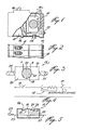
- la Figure 1 est une vue en coupe partielle et simplifiée, montrant le module disjoncteur électrique amélioré suivant la présente invention ;
- la Figure 2 est une vue de plan montrant le module disjoncteur amélioré et superposé à d'autres modules à l'intérieur d'un panneau de distribution électrique ;
- la Figure 3 est une vue de plan illustrant un élément interrupteur commandé de type thermo-mécanique ;
- la Figure 4 est un diagramme schématique simplifié montrant le branchement de l'élément interrupteur commandé à l'intérieur du module disjoncteur ; et
- la Figure 5 est une vue en coupe illustrant l'agencement fondamental de l'élément interrupteur thermo-mécanique de la Figure 3.
- Figure 1 is a partial sectional view and simplified, showing the improved electric circuit breaker module according to the present invention;
- Figure 2 is a plan view showing the improved circuit breaker module and superimposed on other modules inside an electrical distribution panel;
- Figure 3 is a plan view illustrating a controlled switch element of thermo-mechanical type;
- Figure 4 is a simplified schematic diagram showing the connection of the controlled switch element inside the circuit breaker module; and
- Figure 5 is a sectional view illustrating the basic arrangement of the thermo-mechanical switch element of Figure 3.
Se référant maintenant aux dessins et plus particulièrement aux Figures 1 à 3, le module disjoncteur électrique de la -présente invention est généralement désigné par le repère 10. Le module est constitué d'une enceinte conventionnelle formée d'un matériau isolant et loge un interrupteur mécanique 16 couplé à un élément 12 de protection contre les surintensités (voir Figure 4).Referring now to the drawings and more particularly to Figures 1 to 3, the electrical circuit breaker module of the present invention is generally designated by the
De plus, comme illustré à la Figure 2, les modules disjoncteurs 10 sont habituellement fixés à un coffret de branchement par empilage les uns sur les autres. Chaque module peut comporter un ou plusieurs raccords de repérage 13 et un ou plusieurs raccords électriques 14 de sorte à relier un module à un circuit de dérivation électrique particulier parmi la pluralité de circuits entrant et sortant du coffret de branchement, comme il est bien connu dans l'art.In addition, as illustrated in FIG. 2, the
Les modules peuvent être également de type pouvant incorporer des éléments fusibles de type à vis ou à cartouche tubulaire qui peuvent être fixes de iaçon amovible sur la face avant du module. Ces modules sont de construction différente de ceux illustrés aux Figures 1 et 2 mais sont de façon similaire empiles les uns sur les autres et/ou côte à côte.The modules can also be of the type which can incorporate fusible elements of the screw or cartridge type. tubular which can be fixed in a removable way on the front of the module. These modules are of different construction from those illustrated in Figures 1 and 2 but are similarly stacked on top of each other and / or side by side.
La présente invention est relative à une amélioration d'un tel module disjoncteur dans lequel un élément interrupteur commandé 15 est inséré à l'intérieur de ce même module 10 sans avoir à modifier l'épaisseur du module pris suivant le plan vertical. Comme illustré à la Figure 4, cet élément interrupteur 1.5 est relié en série avec l'élément disjoncteur 12. Comme montré à la Figure 2, le module disjoncteur est pourvu d'un bouton de commande manuel 16 permettant au disjoncteur d'occuper la position "ON" ou "OFF".The present invention relates to an improvement of such a circuit breaker module in which a controlled
En ce qui concerne le dispositif interrupteur commandé 15, celui-ci est mis en fonctionnement à distance, par rapport au coffret de branchement et peut être activé à l'aide d'un signal électrique, en ce cas-ci une source de faible puissance reliée à la prise 18 permettant d'activer ou désactiver l'élémentinter- rupteur 15. La commande pourra être produite par l'utilisateur lui-même et/ou la société d'exploitation qui est propriétaire du réseau de transport d'énergie. On conçoit également la possibilité de contrôler l'élément interrupteur 15 suivant une programmation établie de sorte à enclencher et déclencher le circuit électrique couplé au module disjoncteur 10 à des heures et suivant des conditions prédéterminées durant la journée de sorte à commander divers appareils électriques reliés aux circuits de dérivation.Regarding the controlled
Se référant maintenant aux Figures 3 et 5, on décrira l'arrangement de l'élément interrupteur 15 qui y est illustré. Il est à noter cependant que l'élément interrupteur 15 peut être constitué d'un interrupteur électronique ou d'autres moyens. Tout ce qui est en fait requis est que l'interrupteur soit de dimension relativement petite et soit capable de fonctionner à très faible puissance et qu'il soit de plus apte à enclencher et déclencher des circuits de dérivation fonctionnant à des tensions de 110 ou 220 Volts par exemple, lesquelles correspondent aux tensions habituellement utilisées au niveau résidentiel et commercial.Referring now to Figures 3 and 5, we will describe the arrangement of the
L'élément interrupteur 15 est constitué d'un interrupteur thermo-mécanique comportant un élément d'actionnement formé d'un disque bi-métallique 19, sensible à la température, sur lequel est fixé un élément conducteur chauffant 20 susceptible de provoquer une déformation du disque lorsque celui-ci est chauffé. Comme illustré, en particulier à la Figure 5, le disque est de construction concave/convexe et formé d'un matériau bi-métallique de sorte que la chauffe du disque amène celui-ci à se dilater et à se déplacer de sa position normale à une autre position désignée par 19' à la Figure 5.The switching
Le disque 19 est maintenu à l'aide d'une paroi latérale rigide 26 qui permet la déflection du disque dans la position 19'. Une tige rigide 17 relie la surface inférieure 21 du disque 19 au bras 22 de l'interrupteur de sorte que lorsque le disque est chauffé et occupe la position montrée en 19', le contact 22 est ouvert (comme montré par les lignes pointillées) ouvrant ainsi le circuit de dérivation associé 23 relié au module disjoncteur logeant l'élément interrupteur 15.The
Comme montré à la figure 3,1e disque 19 possède une configuration circulaire alors que l'élément filiforme chauffant 20 est disposé en serpentin sur une large partie de la surface du disque 19. Le disque 19 peut également être formé d'une bande bi-métallique rectangulaire. L'interrupteur est actionné en appliquant une tension à travers les bornes A et B de l'élément filiforme chauffant. L'enceinte 24 de l'interrupteur est reliée en série à la ligne 23 du circuit de dérivation à l'aide des conducteurs de bout 25.As shown in FIG. 3,1e
Un avantage du présent interrupteur thermo-mécanique à disque réside dans la très faible puissance requise à son actionnement. De plus, la construction du disque permet une action rapide d'interruption de l'alimentation du circuit électrique 23 qui peut être soumis à un courant de 30 ampères, par exemple. Ainsi, l'agencement particulier de cet interrupteur perme de l'incorporer à l'intérieur du module logeant le disjoncteur conventionnel et de réaliser les divers avantages décrits antérieurement.An advantage of the present thermo-mechanical disc switch lies in the very low power required for actuation. In addition, the construction of the disc allows rapid action to interrupt the supply of the
Il est entendu que la présente invention n'est pas restreinte au seul mode de réalisation préféré décrit ci-haut mais s'étend à toute modification évidente de celui-ci, sous réserve de la porté des revendications annexées.It is understood that the present invention is not limited to the single preferred embodiment described above but extends to any obvious modification thereof, subject to the scope of the appended claims.
Claims (11)
Applications Claiming Priority (2)
| Application Number | Priority Date | Filing Date | Title |
|---|---|---|---|
| US313214 | 1981-10-20 | ||
| US06/313,214 US4434413A (en) | 1981-10-20 | 1981-10-20 | Electrical circuit breaker module |
Publications (2)
| Publication Number | Publication Date |
|---|---|
| EP0077568A2 true EP0077568A2 (en) | 1983-04-27 |
| EP0077568A3 EP0077568A3 (en) | 1985-10-23 |
Family
ID=23214818
Family Applications (1)
| Application Number | Title | Priority Date | Filing Date |
|---|---|---|---|
| EP82109649A Withdrawn EP0077568A3 (en) | 1981-10-20 | 1982-10-19 | Circuit-breaker with actuation which can be programmed |
Country Status (4)
| Country | Link |
|---|---|
| US (1) | US4434413A (en) |
| EP (1) | EP0077568A3 (en) |
| JP (1) | JPS58135534A (en) |
| CA (1) | CA1184224A (en) |
Cited By (2)
| Publication number | Priority date | Publication date | Assignee | Title |
|---|---|---|---|---|
| FR2574218A1 (en) * | 1984-12-03 | 1986-06-06 | Merlin Gerin | Effector for a modular installation for domestic distribution and management of electrical energy |
| WO1998002896A1 (en) * | 1996-07-15 | 1998-01-22 | Gewiss S.P.A. | Modular automatic electric breaker with optimization of used spaces |
Families Citing this family (4)
| Publication number | Priority date | Publication date | Assignee | Title |
|---|---|---|---|---|
| US4616206A (en) * | 1984-09-07 | 1986-10-07 | Eaton Corporation | Circuit breaker and shunt trip apparatus combined within single pole device |
| US5373411A (en) * | 1991-09-30 | 1994-12-13 | Eaton Corporation | Remote control circuit breaker system |
| US5301083A (en) * | 1991-09-30 | 1994-04-05 | Eaton Corporation | Remote control residential circuit breaker |
| AUPQ831100A0 (en) * | 2000-06-22 | 2000-07-13 | Alcatel | Bi-stable microswitch including shape memory alloy latch |
Citations (3)
| Publication number | Priority date | Publication date | Assignee | Title |
|---|---|---|---|---|
| US2471924A (en) * | 1943-07-10 | 1949-05-31 | Metals & Controls Corp | Thermal relay |
| US4164719A (en) * | 1978-04-03 | 1979-08-14 | Gould Inc. | Load management apparatus for residential load centers |
| US4272687A (en) * | 1979-03-05 | 1981-06-09 | Borkan William N | Power manageable circuit breaker |
-
1981
- 1981-10-20 US US06/313,214 patent/US4434413A/en not_active Expired - Lifetime
-
1982
- 1982-04-21 CA CA000401371A patent/CA1184224A/en not_active Expired
- 1982-10-19 EP EP82109649A patent/EP0077568A3/en not_active Withdrawn
- 1982-10-19 JP JP57184412A patent/JPS58135534A/en active Pending
Patent Citations (3)
| Publication number | Priority date | Publication date | Assignee | Title |
|---|---|---|---|---|
| US2471924A (en) * | 1943-07-10 | 1949-05-31 | Metals & Controls Corp | Thermal relay |
| US4164719A (en) * | 1978-04-03 | 1979-08-14 | Gould Inc. | Load management apparatus for residential load centers |
| US4272687A (en) * | 1979-03-05 | 1981-06-09 | Borkan William N | Power manageable circuit breaker |
Cited By (2)
| Publication number | Priority date | Publication date | Assignee | Title |
|---|---|---|---|---|
| FR2574218A1 (en) * | 1984-12-03 | 1986-06-06 | Merlin Gerin | Effector for a modular installation for domestic distribution and management of electrical energy |
| WO1998002896A1 (en) * | 1996-07-15 | 1998-01-22 | Gewiss S.P.A. | Modular automatic electric breaker with optimization of used spaces |
Also Published As
| Publication number | Publication date |
|---|---|
| US4434413A (en) | 1984-02-28 |
| JPS58135534A (en) | 1983-08-12 |
| EP0077568A3 (en) | 1985-10-23 |
| CA1184224A (en) | 1985-03-19 |
Similar Documents
| Publication | Publication Date | Title |
|---|---|---|
| EP0177380B1 (en) | Switching device with a variable composition by means of modular elements | |
| FR2786924A1 (en) | THERMAL FUSE | |
| FR2492157A1 (en) | COMBINED STARTING AND PROTECTING DEVICE FOR SINGLE PHASE ELECTRIC MOTOR USING STARTING THERMISTOR | |
| FR2984006A1 (en) | HOUSING FOR OVERVOLTAGE PROTECTION DEVICE AND ASSOCIATED OVERVOLTAGE PROTECTION DEVICE. | |
| FR2584529A1 (en) | ELECTRIC CIRCUIT BREAKER, ESPECIALLY FOR CAPACITOR BATTERIES | |
| CA1184224A (en) | Programmable control circuit-braker | |
| FR2480030A1 (en) | REMOTELY REENCLENCHABLE CIRCUIT BREAKER INSENSABLE FOR AMBIENT TEMPERATURE VARIATIONS | |
| FR2568408A1 (en) | DEVICE FOR CHECKING FUSES | |
| US6057751A (en) | Overheat and overload sensing device | |
| EP2743959B1 (en) | Thermal trip device and current breaking apparatus comprising one such device | |
| EP2743958B1 (en) | Electric current breaking apparatus, in particular a coupling breaker | |
| EP0834975B1 (en) | Electrical distribution terminal with hybrid limiter block | |
| EP0218491B1 (en) | Device for facilitating electric switching, in particular for contact relays or contactors or other similar remote control devices | |
| FR2935834A1 (en) | Electric current switching device i.e. electromechanical relay, for electrical distribution box of motor vehicle, has protection device selecting connection between supply terminals when exterior temperature of relay is higher than value | |
| EP0089903B1 (en) | Mains socket with differential protection | |
| FR2583192A1 (en) | IMPROVEMENT IN ELECTRIC REMOTE CONTROL DEVICES | |
| EP0782757B1 (en) | Power limiting device for electric installation | |
| EP2743957B1 (en) | Electric current breaking apparatus, in particular a coupling breaker | |
| FR2902232A1 (en) | Electrical component e.g. defective battery element, by-pass device for spacecraft, has switch with line providing continuity between studs, and shaft including prong with thread and retained by release made of phase change material | |
| EP0881653A1 (en) | Fuse-holder device such as a well fuse for electrical apparatus | |
| FR2771587A1 (en) | Shunt for failed low-voltage electric lamps connected in series | |
| FR2879033A1 (en) | DEVICE FOR PROTECTING AN ELECTRICAL INSTALLATION, METHOD AND USE THEREOF | |
| EP2743956B1 (en) | Electric current breaking apparatus, in particular a coupling breaker | |
| EP0579568A1 (en) | Bipolar switch | |
| FR2767766A1 (en) | Preventing unauthorized use of motor vehicle |
Legal Events
| Date | Code | Title | Description |
|---|---|---|---|
| PUAI | Public reference made under article 153(3) epc to a published international application that has entered the european phase |
Free format text: ORIGINAL CODE: 0009012 |
|
| AK | Designated contracting states |
Designated state(s): AT BE CH DE FR GB IT LI LU NL SE |
|
| PUAL | Search report despatched |
Free format text: ORIGINAL CODE: 0009013 |
|
| AK | Designated contracting states |
Designated state(s): AT BE CH DE FR GB IT LI LU NL SE |
|
| 17P | Request for examination filed |
Effective date: 19860122 |
|
| 17Q | First examination report despatched |
Effective date: 19860919 |
|
| STAA | Information on the status of an ep patent application or granted ep patent |
Free format text: STATUS: THE APPLICATION IS DEEMED TO BE WITHDRAWN |
|
| 18D | Application deemed to be withdrawn |
Effective date: 19870130 |
|
| RIN1 | Information on inventor provided before grant (corrected) |
Inventor name: PELLETIER, JEAN-MARC Inventor name: DION, YVON |