EP0076356B1 - Method and device for the measurement of a component absorbing an infrared, near infrared, visible or ultraviolet radiation in a mixture - Google Patents
Method and device for the measurement of a component absorbing an infrared, near infrared, visible or ultraviolet radiation in a mixture Download PDFInfo
- Publication number
- EP0076356B1 EP0076356B1 EP82101068A EP82101068A EP0076356B1 EP 0076356 B1 EP0076356 B1 EP 0076356B1 EP 82101068 A EP82101068 A EP 82101068A EP 82101068 A EP82101068 A EP 82101068A EP 0076356 B1 EP0076356 B1 EP 0076356B1
- Authority
- EP
- European Patent Office
- Prior art keywords
- filter
- measuring
- range
- constituents
- absorption spectrum
- Prior art date
- Legal status (The legal status is an assumption and is not a legal conclusion. Google has not performed a legal analysis and makes no representation as to the accuracy of the status listed.)
- Expired
Links
Images

Classifications
-
- G—PHYSICS
- G01—MEASURING; TESTING
- G01N—INVESTIGATING OR ANALYSING MATERIALS BY DETERMINING THEIR CHEMICAL OR PHYSICAL PROPERTIES
- G01N21/00—Investigating or analysing materials by the use of optical means, i.e. using sub-millimetre waves, infrared, visible or ultraviolet light
- G01N21/17—Systems in which incident light is modified in accordance with the properties of the material investigated
- G01N21/25—Colour; Spectral properties, i.e. comparison of effect of material on the light at two or more different wavelengths or wavelength bands
- G01N21/31—Investigating relative effect of material at wavelengths characteristic of specific elements or molecules, e.g. atomic absorption spectrometry
- G01N21/314—Investigating relative effect of material at wavelengths characteristic of specific elements or molecules, e.g. atomic absorption spectrometry with comparison of measurements at specific and non-specific wavelengths
-
- G—PHYSICS
- G01—MEASURING; TESTING
- G01N—INVESTIGATING OR ANALYSING MATERIALS BY DETERMINING THEIR CHEMICAL OR PHYSICAL PROPERTIES
- G01N21/00—Investigating or analysing materials by the use of optical means, i.e. using sub-millimetre waves, infrared, visible or ultraviolet light
- G01N21/17—Systems in which incident light is modified in accordance with the properties of the material investigated
- G01N21/59—Transmissivity
- G01N21/61—Non-dispersive gas analysers
Definitions
- the invention relates on the one hand to a method and on the other hand to a device for measuring the concentration of a gas absorbing IR, NIR, VIS or UV radiation in a gas matrix or a substance dissolved in a solvent.
- the measured value is usually obtained by comparing two luminous fluxes, namely a luminous flux strongly influenced by the measuring object and a luminous flux to a lesser extent or not at all influenced by the measuring object .
- measuring methods and devices are known in which the light streams simultaneously run through geometrically separate light paths (first option) or in which the two light streams pass through the same light path in time (second option).
- two filter cuvettes filled with different gases or dissolved substances or two interference filters are introduced into the beam path in a periodic sequence.
- the filter functions are selected so that only one of the two successive luminous fluxes can be significantly influenced by the measurement object.
- the use of gases or dissolved substances as filters (“negative selective modulation”) is a correlation photometer, while the use of interference filters (“positive selective modulation”) is a bifrequency photometer. Both correlation and bifrequency photometers can be operated with the same electronic device for evaluation.
- a correlation photometer is known in which the quotient (IM-I R ) / I R is used as a measure of the concentration of the measurement object in the optical beam path.
- IM and I R mean the intensities of the measurement or reference signal.
- the difference signal I M -I R is obtained by phase-sensitive rectification of the detector signal with the frequency ⁇ , where w is the modulation angular frequency.
- the light intensity is additionally modulated with the frequency w 'during the reference signal phase using mechanical means, which is far higher than ⁇ , and the detector signal is phase-sensitive rectified with the frequency w'. The quotient mentioned is then formed.
- the component mixture containing the measurement component being contained in a measurement space which is part of a gas exchange cell.
- the gas exchange cell consists of two hermetically cylindrical gas chambers which are hermetically sealed off from one another, can be set in rotation overall, and is penetrated by the radiation from a radiation source, to which a modulator acts.
- the modulator consists of an aperture wheel with a large number of different segments immediately following one another in the direction of rotation, each second segment being impermeable to the radiation. It is therefore used in a downstream photodetector of two different, periodically successive spectral states in connection with dark phases.
- these dark phases are primarily used for multiple subdivision of the spectral states caused by the double subdivision of the gas exchange cell in the direction of rotation and the multiple subdivision of the modulator in the direction of rotation, in order to achieve a large difference in the measuring frequencies.
- the intensity modulation is carried out at 360 Hz, while the wavelength modulation is carried out at a frequency of 30 Hz.
- the signal is initially amplified and demodulated with a carrier frequency of 360 Hz, the further processing takes place using a 30 Hz signal of the frequency sidebands.
- the two measuring channels are therefore relatively far apart, at the same time being independent of one another, so that no optimization of the resulting signal / noise ratio is possible.
- the invention is based on the object, the method and the device of the discussed US A to be designed in such a way that on the basis of correlation or bi-frequency photometry, at least one method or device is achieved which requires significantly less mechanical effort and at the same time improves the linearity of the raw measured value at the input of the linearization circuit; the latter is intended to improve the accuracy of measurement, in particular at high measurement object concentrations.
- the solution according to the invention is simple in terms of construction, easy to adjust in terms of the associated apparatus, can also be used in free-beam processes and is insensitive to changes in Beam path, such as those caused by window soiling.
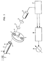
- the basic structure of the single-beam photometer according to FIG. 1 has a radiator 1, namely, for example in the IR range, a thermal radiator that emits radiation and a measuring space 4 with the measuring substance contained therein, which measuring space 4 passes through the measuring radiation becomes.
- the measuring room 4 is sealed off from its surroundings by means of windows 2 and 3, which are transparent to the measuring radiation in the spectral region of interest.
- the measuring room 4 can for example exist in a closed room, in particular in a cuvette; however, it can also be a process room itself, so that the measuring method is then a free jet method.
- the spectral distribution of the light intensity undergoes a change which is characteristic of the concentration of the measurement object.
- the radiation is modulated by an aperture wheel 5 rotating with an angular frequency w, both with regard to the intensity and in spectral terms.
- the mode of operation of the diaphragm wheel 5 acting as a modulator will be explained in more detail below.
- the radiation is focused by means of a lens 8 onto a detector 10, which can be, for example, a pyroelectric receiver or a semiconductor detector in the IR and NIR range.
- a detector 10 can be, for example, a pyroelectric receiver or a semiconductor detector in the IR and NIR range.
- the filters 6 and 7 provided in the diaphragm wheel 5 are gas filters, there is also a fixed interference filter 9 in the beam path.
- the modulator diaphragm wheel 5 can also be arranged between the radiator 1 and the measuring room 4 or even in the measuring room 4 itself. Otherwise, the photometer of FIG. 1 has a Fourier analyzer 27, a divider or quotient images 26 and a display device 23.
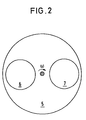
- the exemplary embodiment of the modulator diaphragm wheel 5 shown schematically in FIG. 2 has two interference filters 6, 7, which are pivoted into the beam path alternately with the angular frequency ⁇ - based on the diaphragm wheel 5, so that the radiation is provided by a total of two filters is modulated with the angular frequency 2w.
- the transmission maximum of the filter 6 lies at that wavelength ⁇ A at which the component A to be measured in its concentration has its absorption band. If the interference filter 6 is first in the beam path, the interference filter 7 then follows with the center wavelength ⁇ o, which is not in the range of the absorption bands of the component A to be measured.
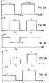
- the radiation from the radiator 1 is therefore subject to a temporal and spectral modulation, as is shown schematically in FIGS. 3A to 3E.
- 3A shows the periodic change in the light intensity without the measurement component being present, which is why no radiation absorption is caused.
- 3B schematically shows the corresponding spectral distribution of the intensities 1 1 and 1 2 .
- the absorption by the measuring component A causes a defect in the transmission ( ⁇ A 1) of the measuring section at a specific spectral point ⁇ A (FIG. 3C). This leads to a weakening of the light intensity l 1 at ⁇ A , while the light intensity 1 2 remains unaffected (FIG. 3D).
- 3E shows the effect of the measuring component A on the temporal sequence of the light intensity.
- the measurement effect therefore consists in the difference between the signals in FIGS. 3A and 3E.
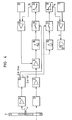
- the evaluation of the output signal of the detector 10 is carried out by means of measurement processing electronics, which essentially consists of a two-channel lock-in amplifier, the mode of operation of which explains the block diagram of FIG. 4.
- the intensity of the light of the radiator 1, which is modulated by the modulator aperture wheel 5 with the angular frequency ⁇ , is converted in the detector 10 into an electrical signal, which is first raised by a preamplifier 13 and then by a controllable amplifier 14.
- the detector signal treated in this way is then broken down into parts of its frequency spectrum (Fourier analysis).
- the signal component with the frequency m is extracted by a selective filter 15 and rectified in phase synchronism with ⁇ by a rectifier 17; after subsequent smoothing in a low pass 19, this then leads to a smoothed signal S i for the first measuring channel.
- the procedure is similar in the second measuring channel.
- a filter 16 selects the signal component with the frequency 2 ⁇ , which is rectified by a rectifier 18 in phase synchronization with 2 ⁇ .
- the control signals for ⁇ and 2w are generated by a reference signal amplifier 24 and a phase shifter 25.
- the signal of the second measuring channel is sieved by an integrator 20 and passed to a control amplifier 21, which compares the signal S 2 with a reference voltage of a reference voltage generator 22 and keeps it constant via the controllable amplifier 14. This ensures that the signal S 1 of the first measuring channel smoothed by the low pass 19, which is finally displayed on a display device 23 by means of a display amplifier 12, is the quotient of the first and second Fourier coefficients of the signal mixture from FIGS. 3A and 3E is proportional.
- a DC voltage of a DC voltage generator 11 can be superimposed on the signal S 1 for compensation purposes.
- the analysis of the temporal signal curve shows for the first and the second Fourier coefficients F 1 and F 2 on the assumption that the geometric shapes of the filter holders of the modulator diaphragm wheel 5 are exactly the same:
- a 1 and b 1 are device constants, which are determined by the geometric arrangement.
- the measurement signal displayed is the quotient of these two variables:
- the formation of the quotient makes the signal independent of the light intensity and therefore drift-free with regard to “gray”, that is to say spectrally independent, intensity changes, such as are caused, for example, by window contamination.
- the transmission TA of the measuring substance A is an integral function of the spectral transmission, averaged over the interference filter transmission curve at ⁇ A.
- the signal is a strictly monotonically increasing function of the concentration of the measurement component A.
- the sensitivity of the method according to the invention is essentially determined by the effective optical measurement section 1 and by the spectroscopic data of the measurement component A, namely by ⁇ ( ⁇ ), and thus depends on the bifrequency method the choice of the center wavelength and half-width of the interference filter and in the gas filter correlation method on the concentration of the correlation gas in the filter cell.
- the signal S 1 also contains the measurement component transmission in the denominator of the quotient. This does somewhat reduce the sensitivity at low concentrations, but at the same time also compensates for the linearity of the transmission at higher concentrations.
- both interference filters 6 and 7 of the modulation diaphragm wheel 5 have the same integral transmission, because they are subject to fluctuations, for example, due to manufacturing fluctuations with regard to the position of the transmission maximum and the half-value width.
- the radiator 1 and the detector 10 have spectral responses which influence the integral transmission on both measurement channels. Such differences (I 1 -I 2 ) interfere with the device comparison; in particular, the signal S i is not zero when the concentration is zero. This naturally applies to gas filter correlation technology, where the intensities l i and 1 2 are different from the outset due to the selective pre-absorption in the gas filter.
- a device can be provided that is mechanical and acts as an adjustable diaphragm for the gas filter or interference filter that has the higher integral transmission.
- the spectral position ⁇ o of the reference interference filter is selected such that it detects another part of the interference component bands, namely where the measurement component A itself does not absorb or only weakly absorbs it. Then the intensity weakening at ⁇ A is compensated for by the interference component by means of an equally large weakening at ⁇ o.
- both correlation cuvettes can additionally be filled with the interference component, so that the influence of the same in the measuring room 4 is eliminated.
- filtering techniques for example by filter cuvettes permanently installed in the beam path filled with the interference component, can also be used.
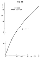
- 5A shows a first application example from the gas analysis, namely the measurement results for a propane measuring device.
- the gas filter correlation was used here, the cuvettes each being filled with 100% by volume N 2 or C 3 H 6 .
- the length of the cuvettes was 150 cm and the spectral range was 3.4 ⁇ m, filtered by a narrow-band interference filter.
- a pyroelectric detector was used in both cases.
- HWB full width at half maximum.
Abstract
Description
Die Erfindung betrifft zum einen ein Verfahren und zum anderen eine Vorrichtung zur Messung der Konzentration eines IR-, NIR-, VIS- oder UV-Strahlung absorbierenden Gases in einer Gasmatrix oder einer in einem Lösungsmittel gelösten Substanz.The invention relates on the one hand to a method and on the other hand to a device for measuring the concentration of a gas absorbing IR, NIR, VIS or UV radiation in a gas matrix or a substance dissolved in a solvent.
Mit Hilfe von nichtdispersiven Gaskonzentrationsmessgeräten, also auf optischer Basis arbeitenden Gasanalysatoren, die weder Gitter noch Prismen enthalten, wird der Messwert gewöhnlich aus dem Vergleich zweier Lichtströme gewonnen, nämlich einem vom Messobjekt stark beeinflussten Lichtstrom und einem vom Messobjekt in geringerem Umfang oder gar nicht beeinflussten Lichtstrom.With the help of non-dispersive gas concentration measuring devices, i.e. gas analyzers working on an optical basis, which contain neither grids nor prisms, the measured value is usually obtained by comparing two luminous fluxes, namely a luminous flux strongly influenced by the measuring object and a luminous flux to a lesser extent or not at all influenced by the measuring object .
Für diese Art der Konzentrationsmessung sind Messverfahren und -geräte bekannt, bei denen die Lichtströme gleichzeitig geometrisch voneinander getrennte Lichtwege durchlaufen (erste Möglichkeit) oder bei denen die beiden Lichtströme denselben Lichtweg zeitlich nacheinander durchlaufen (zweite Möglichkeit).For this type of concentration measurement, measuring methods and devices are known in which the light streams simultaneously run through geometrically separate light paths (first option) or in which the two light streams pass through the same light path in time (second option).
Bei der Verfahrensweise nach der zweiten Möglichkeit werden beispielsweise zwei mit unterschiedlichen Gasen oder gelösten Substanzen gefüllte Filterküvetten oder zwei Interferenzfilter, deren Zentrumswellenlängen sich unterscheiden, in periodischer Folge in den Strahlengang eingeführt. Die Filterfunktionen sind dabei so gewählt, dass jeweils nur einer der beiden aufeinander folgenden Lichtströme wesentlich vom Messobjekt beeinflusst werden kann. Bei Messgeräten der oben erwähnten zweiten Möglichkeit handelt es sich bei der Verwendung von Gasen oder gelösten Substanzen als Filter («negative Selektivmodulation») um Korrelationsphotometer, während es sich bei der Verwendung von Interferenzfiltern («positive Selektivmodulation») um Bifrequenzphotometer handelt. Sowohl Korrelations- als auch Bifrequenzphotometer könne mit derselben elektronischen Einrichtung zur Auswertung betrieben werden.In the procedure according to the second possibility, for example, two filter cuvettes filled with different gases or dissolved substances or two interference filters, the center wavelengths of which differ, are introduced into the beam path in a periodic sequence. The filter functions are selected so that only one of the two successive luminous fluxes can be significantly influenced by the measurement object. In the case of measuring devices of the second possibility mentioned above, the use of gases or dissolved substances as filters (“negative selective modulation”) is a correlation photometer, while the use of interference filters (“positive selective modulation”) is a bifrequency photometer. Both correlation and bifrequency photometers can be operated with the same electronic device for evaluation.
Aus Rev. Sci. Instrum., 49, Seite 1520 (1978) ist ein Korrelationsphotometer bekannt, bei dem der Quotient (IM-IR)/IR als Mass für die Konzentration des Messobjekts im optischen Strahlengang verwendet wird. Dabei bedeuten IM und IR die Intensitäten des Mess- bzw. Referenzsignals. Das Differenzsignal IM-IR wird dabei durch phasenempfindliche Gleichrichtung des Detektorsignals mit der Frequenz ω gewonnen, wobei w die Modulationskreisfrequenz ist.From Rev. Sci. Instrum., 49, page 1520 (1978), a correlation photometer is known in which the quotient (IM-I R ) / I R is used as a measure of the concentration of the measurement object in the optical beam path. IM and I R mean the intensities of the measurement or reference signal. The difference signal I M -I R is obtained by phase-sensitive rectification of the detector signal with the frequency ω, where w is the modulation angular frequency.
Zur Bestimmung von IR wird während der Referenzsignalphase die Lichtintensität unter Verwendung mechanischer Mittel zusätzlich mit der Frequenz w' moduliert, die weit höher als ω liegt, und das Detektorsignal mit der Frequenz w' phasenempfindlich gleichgerichtet. Hieran anschliessend wird der erwähnte Quotient gebildet.To determine I R , the light intensity is additionally modulated with the frequency w 'during the reference signal phase using mechanical means, which is far higher than ω, and the detector signal is phase-sensitive rectified with the frequency w'. The quotient mentioned is then formed.
Aus US-A-3 878 107 sind ein Verfahren und eine Vorrichtung zur Messung kleiner Mengen eines Gases enthalten in anderen Gasen bekannt, wobei das die Messkomponente enthaltende Komponentengemisch in einem Messraum enthalten ist, der Bestandteil einer Gas-Wechselzelle ist. Die Gas-Wechselzelle besteht ihrerseits aus zwei hermetisch gegeneinander abgeschlossenen, nebeneinanderliegenden hablzylindrischen Gasräumen, ist insgesamt in Rotation versetzbar, und wird von der Strahlung einer Strahlenquelle durchsetzt, auf die ein Modulator einwirkt. Der Modulator besteht aus einem Blendenrad mit einer Vielzahl von in Rotationsrichtung unmittelbar aufeinanderfolgenden unterschiedlichen Segmenten, wobei jedes zweite Segment für die Strahlung undurchlässig ist. Es wird daher in einem nachgeschalteten Fotodetektor von zwei unterschiedlichen, periodisch aufeinanderfolgenden Spektralzuständen in Verbindung mit Dunkelphasen Gebrauch gemacht. Diese Dunkelphasen dienen jedoch in erster Linie zur Mehrfach-Unterteilung der Spektralzustände hervorgerufen durch die Zweifach-Unterteilung der Gas-Wechselzelle in Drehrichtung und die Mehrfach-Unterteilung des Modulators in Drehrichtung, um so eine grosse Differenz der Messfrequenzen zu erzielen. So wird nach den ausdrücklichen Angaben die Intensitätsmodulation mit 360 Hz ausgeführt, während die Wellenlängenmodulation mit einer Frequenz von 30 Hz erfolgt. Während bei dem bekannten Verfahren also zunächst das Signal mit einer Trägerfrequenz von 360 Hz verstärkt und demoduliert wird, erfolgt die Weiterverarbeitung unter Verwendung eines 30 Hz-Signal der Frequenzseitenbänder. Die beiden Messkanäle liegen also verhältnismässig weit auseinander, wobei sie zugleich voneinander unabhängig sind, so dass keine Optimierung des resultierenden Signal/Rausch-Verhältnisses möglich ist. Eine solche Optimierung ist auch mittels des bekannten Verfahrens nicht angestrebt; vielmehr soll dieses einer Vereinfachung und Erleichterung des Abgleichs dienen, wozu die Strahlungsenergie-Durchlässigkeit in dem von der Gas-Wechselzelle gebildeten Korrelationszellensystem mit abwechselnd beaufschlagten Gaszellen zunächst teilweise abgeglichen und sodann der Abgleich des Systems elektronisch durchgeführt wird. Zur Ermöglichung dieses Abgleichs selbst bei Schwankungen der Systemverstärkung erfolgt der elektronische Abgleich der verbleibenden kleinen optischen Unbalance durch multiplikative Signalverarbeitung.From US-A-3 878 107 a method and a device for measuring small amounts of a gas contained in other gases are known, the component mixture containing the measurement component being contained in a measurement space which is part of a gas exchange cell. For its part, the gas exchange cell consists of two hermetically cylindrical gas chambers which are hermetically sealed off from one another, can be set in rotation overall, and is penetrated by the radiation from a radiation source, to which a modulator acts. The modulator consists of an aperture wheel with a large number of different segments immediately following one another in the direction of rotation, each second segment being impermeable to the radiation. It is therefore used in a downstream photodetector of two different, periodically successive spectral states in connection with dark phases. However, these dark phases are primarily used for multiple subdivision of the spectral states caused by the double subdivision of the gas exchange cell in the direction of rotation and the multiple subdivision of the modulator in the direction of rotation, in order to achieve a large difference in the measuring frequencies. According to the express information, the intensity modulation is carried out at 360 Hz, while the wavelength modulation is carried out at a frequency of 30 Hz. While in the known method the signal is initially amplified and demodulated with a carrier frequency of 360 Hz, the further processing takes place using a 30 Hz signal of the frequency sidebands. The two measuring channels are therefore relatively far apart, at the same time being independent of one another, so that no optimization of the resulting signal / noise ratio is possible. Such an optimization is also not aimed at using the known method; rather, this is intended to simplify and facilitate the adjustment, for which purpose the radiant energy permeability in the correlation cell system formed by the gas exchange cell is initially partially compared with alternately charged gas cells and then the adjustment of the system is carried out electronically. To enable this adjustment, even in the event of fluctuations in the system gain, the remaining small optical imbalance is electronically adjusted by multiplicative signal processing.
Aus DE-A-2 643 331 ist in Verbindung mit einer Vorrichtung zur Messung der Strahlungsabsorption mittels modulierter Strahlung eine Signalauswertung bekannt. Die Vorrichtung zur Messung der Strahlungsabsorption besteht dabei jedoch in einem Zweistrahlphotometer, so dass für die Signalauswertung auch zwei auf die unterschiedlichen Strahlengänge zurückzuführende Signale zur Verfügung stehen. Die Verwendung dieser bekannten Signalauswertung in Verbindung mit dem Messverfahren der US-A erscheint daher aus naheliegenden Gründen nicht möglich, da bei Weglassung des zweiten Strahls die zweite Signalkomponente für die Quotientenbildung fehlt.From DE-A-2 643 331 a signal evaluation is known in connection with a device for measuring radiation absorption by means of modulated radiation. However, the device for measuring the radiation absorption consists of a two-beam photometer, so that two signals which are attributable to the different beam paths are also available for the signal evaluation. The use of this known signal evaluation in connection with the measurement method of US-A therefore does not appear to be possible for obvious reasons, since if the second beam is omitted, the second signal component for the quotient formation is missing.
Der Erfindung liegt die Aufgabe zugrunde, das Verfahren und die Vorrichtung der erörterten US-A so auszubilden, dass auf der Basis der Korrelations- oder Bi-Frequenzphotometrie mindestens ein Verfahren bzw. eine Vorrichtung erreicht wird, die einen wesentlich geringeren mechanischen Aufwand erforderlich machen und gleichzeitig die Linearität des Rohmesswertes am Eingang der Linearisierungschaltung verbessern; letzteres soll der Verbesserung der Messgenauigkeit insbesondere bei hohen Messobjektkonzentrationen dienen.The invention is based on the object, the method and the device of the discussed US A to be designed in such a way that on the basis of correlation or bi-frequency photometry, at least one method or device is achieved which requires significantly less mechanical effort and at the same time improves the linearity of the raw measured value at the input of the linearization circuit; the latter is intended to improve the accuracy of measurement, in particular at high measurement object concentrations.
Erfindungsgemäss wird diese Aufgabe in verfahrenstechnischer bzw. vorrichtungstechnischer Hinsicht durch die Gesamtheit der Merkmale der Patentansprüche 1 bzw. 6 gelöst.According to the invention, this object is achieved in terms of process technology or device technology by the entirety of the features of
Vorteilhafte Weiterbildungen sowohl in verfahrenstechnischer als auch in vorrichtungstechnischer Hinsicht sind aus den jeweils zugehörigen Unteransprüchen 2 bis 5 bzw. 7 bis 12 zu ersehen.Advantageous further developments both in terms of process technology and in terms of device technology can be seen from the associated
Erfindungsgemäss wird also im Wege der nichtdispersiven Einstrahl-Photometrie unter Verwendung eines Gasfilter- oder Interferenzfilter-Karussells als Modulationseinrichtung gearbeitet. Durch die Modulation werden der Messstrahlung, die beim Durchgang durch die Messstrecke eine für die Messsubstanz spezifische spektrale Absorption erfährt, zeitlich nacheinander zwei unterschiedliche spektrale Verteilungsfunktionen aufgeprägt, die durch Dunkelphasen voneinander getrennt sind. Die so modulierte Strahlung trifft dann auf einen Detektor, dessen Ausgangssignal einer elektronischen Fourieranalyse unterzogen wird. Der Quotient aus erstem und zweitem Fourierkoeffizienten stellt das Mass für die Konzentration der optisch absorbierenden Substanz dar. Die erfindungsgemässe Lösung ist im Vergleich zur Zweistrahl-Photometrie einfach in konstruktiver Hinsicht des zugehörigen apparativen Aufbaus, einfach abzugleichen, auch bei Freistrahlverfahren einsetzbar und unempfindlich gegenüber Veränderungen im Strahlengang, wie sie beispiels weise durch Fensterverschmutzungen hervorgerufen werden.According to the invention, work is therefore carried out using non-dispersive single-beam photometry using a gas filter or interference filter carousel as a modulation device. The modulation imparts two different spectral distribution functions, which are separated from one another by dark phases, to the measurement radiation, which experiences a spectral absorption specific to the measurement substance as it passes through the measurement section. The radiation modulated in this way then strikes a detector, the output signal of which is subjected to an electronic Fourier analysis. The quotient of the first and second Fourier coefficients represents the measure of the concentration of the optically absorbing substance. Compared to double-beam photometry, the solution according to the invention is simple in terms of construction, easy to adjust in terms of the associated apparatus, can also be used in free-beam processes and is insensitive to changes in Beam path, such as those caused by window soiling.
Im folgenden wird die Erfindung beispielhaft und unter gleichzeitiger Bezugnahme auf die Zeichnungen weiter ins einzelne gehend erläutert; in den Zeichnungen zeigen:
- Fig. 1 schematisch den grundsätzlichen Aufbau einer erfindungsgemässen Messvorrichtung,
- Fig. 2 den Blendenradmodulator der Fig. 1,
- Fig. 3A den periodischen Wechsel der Lichtintensität in der Strahlung, wenn keine Messkomponente vorliegt, die eine Strahlungsabsorption zur Folge hätte,
- Fig. 3B schematisch die entsprechende Spektralverteilung der Intensität,
- Fig. 3C den Transmissionsverlauf bei durch die Messkomponente bedingter Absorption,
- Fig. 3D die Abschwächung der einen Lichtintensität bei unveränderter Aufrechterhaltung der anderen Lichtintensität,
- Fig. 3E den Effekt der Messkomponente auf die zeitliche Abfolge der Lichtintensität,
- Fig. 4 das Blockschaltbild der Messwertverarbeitungselektronik,
- Fig. 5A für ein bestimmtes Anwendungsbeispiel aus der Gasanalyse die zugehörigen Messergebnisse und
- Fig. 5B für ein anderes Anwendungsbeispiel aus der Gasanalyse die hierzu gehörenden Messergebnisse.
- 1 schematically shows the basic structure of a measuring device according to the invention,
- 2 the aperture wheel modulator of FIG. 1,
- 3A shows the periodic change in the light intensity in the radiation when there is no measurement component which would result in radiation absorption,
- 3B schematically shows the corresponding spectral distribution of the intensity,
- 3C shows the transmission curve with absorption caused by the measurement component,
- 3D the attenuation of one light intensity while maintaining the other light intensity,
- 3E the effect of the measurement component on the temporal sequence of the light intensity,
- 4 shows the block diagram of the measurement processing electronics,
- 5A for a specific application example from the gas analysis, the associated measurement results and
- 5B shows the associated measurement results for another application example from gas analysis.
Das Einstrahl-Photometer gemäss Fig. 1 verfügt in seinem grundsätzlichen Aufbau über einen Strahler 1, nämlich beispielsweise im IR-Bereich einen thermischen Strahler, der eine Strahlung emittiert und über einen Messraum 4 mit der darin enthaltenen Messsubstanz, welcher Messraum 4 von der Messstrahlung durchsetzt wird. Der Messraum 4 ist gegenüber seiner Umgebung mit Hilfe von Fenstern 2 und 3 abgedichtet, die im interessierenden Spektralbereich für die Messstrahlung durchlässig sind. Der Messraum 4 kann beispielsweise in einem geschlossenen Raum, insbesondere in einer Küvette, bestehen; er kann aber auch ein Prozessraum selbst sein, so dass es sich dann bei dem Messverfahren um ein Freistrahlverfahren handelt.The basic structure of the single-beam photometer according to FIG. 1 has a radiator 1, namely, for example in the IR range, a thermal radiator that emits radiation and a measuring space 4 with the measuring substance contained therein, which measuring space 4 passes through the measuring radiation becomes. The measuring room 4 is sealed off from its surroundings by means of
Im Messraum 4 erfährt die spektrale Verteilung der Lichtintensität eine für die Konzentration des Messobjekts charakteristische Veränderung. Nach dem Austritt aus dem Messraum 4 durch das Fenster 3 hindurch wird die Strahlung durch ein mit einer Kreisfrequenz w rotierendes Blendenrad 5 moduliert, und zwar sowohl hinsichtlich der Intensität als auch in spektraler Hinsicht. Die Wirkungsweise des als Modulator wirkenden Blendenrads 5 wird weiter unten noch genauer erläutert werden.In the measuring room 4, the spectral distribution of the light intensity undergoes a change which is characteristic of the concentration of the measurement object. After exiting the measuring space 4 through the window 3, the radiation is modulated by an
Im Anschluss an die vom Blendenrad 5 gebildete Modulationseinrichtung wird die Strahlung mittels einer Linse 8 auf einen Detektor 10 fokussiert, der im IR- und im NIR-Bereich beispielsweise ein pyroelektrischer Empfänger oder ein Halbleiterdetektor sein kann. Für den Fall, dass die im Blendenrad 5 vorgesehenen Filter 6 und 7 Gasfilter sind, befindet sich im Strahlengang zusätzlich ein feststehendes Interferenzfilter 9. Das Modulatorblendenrad 5 kann auch zwischen dem Strahler 1 und dem Messraum 4 oder sogar im Messraum 4 selbst angeordnet sein. Im übrigen verfügt das Photometer der Fig. 1 über einen Fourieranalysator 27, einen Dividierer oder Quotientenbilder 26 und eine Anzeigevorrichtung 23.Following the modulation device formed by the
Die in Fig. 2 schematisch dargestellte beispielhafte Ausführungsform des Modulatorblendenrads 5 verfügt über zwei Interferenzfilter 6, 7, die abwechselnd mit der Kreisfrequenz ω - bezogen auf das Blendenrad 5 - in den Strahlengang geschwenkt werden, so dass die Strahlung wegen der Vorsehung von insgesamt zwei Filtern mit der Kreisfrequenz 2w moduliert wird.The exemplary embodiment of the
Das Transmissionsmaximum des Filters 6 liegt bei derjenigen Wellenlänge λA, bei der die in ihrer Konzentration zu messende Komponenten A ihre Absorptionsbande aufweist. Wenn sich das Interferenzfilter 6 als erstes im Strahlengang befindet, folgt anschliessend das Interferenzfilter 7 mit der Zentrumswellenlänge λo, die nicht im Bereich der Absorptionsbanden der zu messenden Komponente A liegt.The transmission maximum of the
Insgesamt unterliegt die Strahlung des Strahlers 1 also einer zeitlichen und spektralen Modulation, wie dies in den Fig. 3A bis 3E schematisch dargestellt ist.Overall, the radiation from the radiator 1 is therefore subject to a temporal and spectral modulation, as is shown schematically in FIGS. 3A to 3E.
Fig. 3A zeigt den periodischen Wechsel der Lichtintensität, ohne dass die Messkomponente vorliegt, weshalb keine Strahlungsabsorption verursacht ist. Fig. 3B zeigt schematisch die entsprechende Spektralverteilung der Intensitäten 11 und 12.3A shows the periodic change in the light intensity without the measurement component being present, which is why no radiation absorption is caused. 3B schematically shows the corresponding spectral distribution of the intensities 1 1 and 1 2 .
Die Absorption durch die Messkomponente A verursacht einen Defekt in der Transmission (τA 1) der Messstrecke bei einer spezifischen Spektralstelle λA (Fig. 3C). Dies führt zu einer Abschwächung der Lichtintensität l1 bei λA, während die Lichtintensität 12 unbeeinflusst bleibt (Fig. 3D).The absorption by the measuring component A causes a defect in the transmission (τ A 1) of the measuring section at a specific spectral point λ A (FIG. 3C). This leads to a weakening of the light intensity l 1 at λ A , while the light intensity 1 2 remains unaffected (FIG. 3D).
In Fig. 3E ist der Effekt der Messkomponente A auf die zeitliche Abfolge der Lichtintensität dargestellt. Der Messeffekt besteht also in dem Unterschied der Signale der Fig. 3A und 3E.3E shows the effect of the measuring component A on the temporal sequence of the light intensity. The measurement effect therefore consists in the difference between the signals in FIGS. 3A and 3E.
Die Auswertung des Ausgangssignals des Detektors 10 erfolgt mittels einer Messwertverarbeitungselektronik, die im wesentlichen aus einem Zwei-Kanal-Lock-In-Verstärker besteht, dessen Arbeitsweise das Blockschaltbild der Fig. 4 erläutert. Die vom Modulatorblendenrad 5 mit der Kreisfrequenz ω modulierte Intensität des Lichts des Strahlers 1 wird im Detektor 10 in ein elektrisches Signal umgesetzt, das zunächst durch einen Vorverstärker 13 und dann durch einen regelbaren Verstärker 14 angehoben wird. Anschliessend erfolgt eine Zerlegung des so behandelten Detektorsignals in Teile seines Frequenzspektrums (Fourieranalyse).The evaluation of the output signal of the
In einem ersten Messkanal wird der Signalanteil mit der Frequenz m durch ein selektives Filter 15 extrahiert und durch einen nachgeschalteten Gleichrichter 17 phasensynchron zu ω gleichgerichtet; dies führt dann nach anschliessender Glättung in einem Tiefpass 19 zu einem geglätteten Signal Si für den ersten Messkanal.In a first measuring channel, the signal component with the frequency m is extracted by a
Ähnlich wird im zweiten Messkanal verfahren. Dort selektiert ein Filter 16 den Signalanteil mit der Frequenz 2ω, das durch einen Gleichrichter 18 phasensynchron zu 2ω gleichgerichtet wird. Die Steuersignale für ω und 2w werden durch einen Referenzsignalverstärker 24 und einen Phasenschieber 25 erzeugt. Das Signal des zweiten Messkanals wird durch einen Integrator 20 gesiebt und auf einen Regelverstärker 21 gegeben, der das Signal S2 mit einer Referenzspannung eines Referenzspannungsgebers 22 vergleicht und über den regelbaren Verstärker 14 konstant hält. Somit ist gewährleistet, dass das durch den Tiefpass 19 geglättete Signal S1 des ersten Messkanals, das mittels eines Anzeigeverstärkers 12 verstärkt schliesslich an einem Anzeigegerät 23 zur Anzeige gebracht wird, dem Quotienten aus erstem und zweitem Fourierkoeffizienten des Signalgemischs aus den Fig. 3A und 3E proportional ist. Dem Signal S1 kann für Kompensationszwecke eine Gleichspannung eines Gleichspannungsgebers 11 überlagert werden.The procedure is similar in the second measuring channel. There, a
Die Analyse des zeitlichen Signalverlaufs ergibt für den ersten und den zweiten Fourierkoeffizienten F1 und F2 unter der Annahme, dass die geometrischen Formen der Filterfassungen des Modulatorblendenrads 5 exakt gleich sind:The analysis of the temporal signal curve shows for the first and the second Fourier coefficients F 1 and F 2 on the assumption that the geometric shapes of the filter holders of the
![]()
![]()
![]()
![]()
Dabei sind a1 und b1 Gerätekonstanten, die durch die geometrische Anordnung bestimmt sind.Here, a 1 and b 1 are device constants, which are determined by the geometric arrangement.
Unter der Annahme, dass die einzelnen Filter 6 und 7 so ausgesucht sind, dass ihre integralen Transmissionen gleich sind, also 11 = 12 gilt, ergeben sich für die Fourierkoeffizienten:![]()
![]()
![]()
![]()
Das zur Anzeige gebrachte Messsignal ist der Quotient aus diesen beiden Grössen:![]()
![]()
Durch die Quotientenbildung wird das Signal unabhängig von der Lichtintensität und damit driftfrei in Hinblick auf «graue», also spektral unabhängige Intensitätsänderungen, wie sie beispielsweise durch eine Fensterverschmutzung bedingt werden.The formation of the quotient makes the signal independent of the light intensity and therefore drift-free with regard to “gray”, that is to say spectrally independent, intensity changes, such as are caused, for example, by window contamination.
Die Transmission TA der Messsubstanz A ist eine Integralfunktion der spektralen Transmission, gemittelt über die Interferenzfilter-Durchlasskurve bei λA.The transmission TA of the measuring substance A is an integral function of the spectral transmission, averaged over the interference filter transmission curve at λ A.
Für kleine Produkte ε(λ) · c . 1, wobei ε(λ) der im Durchlassbereich des Interferenzfilters gemittelte spezifische Absorptionskoeffizient und c die Konzentration der Messkomponente A und 1 die optische Weglänge im Messmedium ist, lässt sich die Transmission in eine Taylorreihe entwickeln:![]()
![]()
Diese Näherung lässt sich durch geeignete Wahl des spektralen Transmissionsfensters des Interferenzfilters sowie der optischen Weglänge 1 des möglicherweise als Küvette ausgebildeten Messraums 4 immer einstellen. Wird die Näherung gemäss Gleichung (6) in Gleichung (5) eingeführt, so erhält man:![]()
![]()
Das Signal ist eine streng monoton wachsende Funktion der Konzentration der Messkomponente A. Die Empfindlichkeit des erfindungsgemässen Verfahrens wird im wesentlichen durch die effektive optische Messstrecke 1 und durch die spektroskopischen Daten der Messkomponente A, nämlich durch ε(λ) bestimmt, hängt also beim Bifrequenzverfahren von der Wahl der Zentrumswellenlänge und Halbwertsbreite der Interferenzfilter und beim Gasfilterkorrelationsverfahren von der Konzentration des Korrelationsgases in der Filterküvette ab.The signal is a strictly monotonically increasing function of the concentration of the measurement component A. The sensitivity of the method according to the invention is essentially determined by the effective optical measurement section 1 and by the spectroscopic data of the measurement component A, namely by ε (λ), and thus depends on the bifrequency method the choice of the center wavelength and half-width of the interference filter and in the gas filter correlation method on the concentration of the correlation gas in the filter cell.
In der Praxis ist ein Kompromiss zu schliessen zwischen der Empfindlichkeit und der Linearität, wobei letzteres nicht ganz so kritisch zu bewerten ist. Gemäss Gleichung (5) enthält das Signal S1 die Messkomponententransmission auch im Nenner des Quotienten. Hierdurch wird zwar etwas die Empfindlichkeit bei kleiner Konzentration reduziert, gleichzeitig aber auch die Linearität der Transmission bei höheren Konzentrationen kompensiert.In practice, a compromise has to be made between the sensitivity and the linearity, whereby the latter is not to be assessed quite as critically. According to equation (5), the signal S 1 also contains the measurement component transmission in the denominator of the quotient. This does somewhat reduce the sensitivity at low concentrations, but at the same time also compensates for the linearity of the transmission at higher concentrations.
Es ist nicht zu erwarten, dass beide Interferenzfilter 6 und 7 des Modulationsblendenrads 5 dieselbe integrale Transmission aufweisen, weil sie beispielsweise durch Fertigungsschwankungen hinsichtlich der Lage des Transmissionsmaximums und der halbwertsbreite Streuungen unterliegen. Darüber hinaus besitzen der Strahler 1 und der Detektor 10 Spektralgänge, die die integrale Transmission auf beiden Messkanälen beeinflussen. Solche Differenzen (I1-I2) stören aber beim Geräteabgleich; insbesondere ist das Signal Si nicht Null, wenn die Konzentration Null ist. Dies gilt naturgemäss für die Gasfilterkorrelationstechnik, wo die Intensitäten li und 12 von vornherein durch die selektive Vorabsorption im Gasfilter unterschiedlich sind.It is not to be expected that both
Zur Kompensation dieser Effekte werden zwei Massnahmen vorgeschlagen. Es kann beispielsweise eine Einrichtung vorgesehen werden, die mechanischer Art ist und als einstellbare Blende für dasjenige Gasfilter oder Interferenzfilter wirkt, das die höhere integrale Transmission besitzt. Diese Blende wird auf dem rotierenden Modulatorblendenrad befestigt und deckt die Strahlöffnung des entsprechenden Filters ab, so dass die Kompensation l1 = 12 ohne Vorliegen der Messkomponente A erfolgt.Two measures are proposed to compensate for these effects. For example, a device can be provided that is mechanical and acts as an adjustable diaphragm for the gas filter or interference filter that has the higher integral transmission. This diaphragm is attached to the rotating modulator diaphragm wheel and covers the beam opening of the corresponding filter, so that the compensation l 1 = 1 2 takes place without the measurement component A being present.
Weit einfacher ist der Abgleich mittels einer elektronischen Einrichtung, die eine konstante Gleichspannung Uo zum Signal S1 addiert (die mit 11 und 12 bezeichneten Elemente gemäss Fig. 4) und so die Kompensation auf Null ermöglicht für den Fall, dass die Konzentration der Messkomponente Null ist:![]()
![]()
Dabei ist b eine Konstante. Der Abgleich bei c = 0 => TA = 1 erfordert nun:![]()
![]()
Ist das Auftreten von Störkomponenten im Messraum zu erwarten, deren Absorptionsbande sich mit denen der Messkomponente überlappen, so sind folgende Kompensationsmassnahmen möglich. Beim Bifrequenzverfahren wählt man die Spektrallage λo des Referenz-Interferenzfilters so, dass dieses einen anderen Teil der Störkomponentenbanden erfasst, nämlich dort, wo die Messkomponente A selbst nicht oder nur schwach absorbiert. Dann wird die Intensitätsschwächung bei λA durch die Störkomponente mittels einer ebenso grossen Schwächung bei λo kompensiert.If interference components are expected to occur in the measuring room, whose absorption bands overlap with those of the measuring component, the following compensation measures are possible. In the bifrequency method, the spectral position λo of the reference interference filter is selected such that it detects another part of the interference component bands, namely where the measurement component A itself does not absorb or only weakly absorbs it. Then the intensity weakening at λ A is compensated for by the interference component by means of an equally large weakening at λo.
Im Falle der Gasfilter-Technik können beide Korrelationsküvetten zusätzlich mit der Störkomponente gefüllt werden, so dass der Einfluss derselben im Messraum 4 eliminiert wird.In the case of gas filter technology, both correlation cuvettes can additionally be filled with the interference component, so that the influence of the same in the measuring room 4 is eliminated.
Selbstverständlich sind die üblichen Filtertechniken, beispielsweise durch fest im Strahlengang installierte Filterküvetten gefüllt mit der Störkomponente, ebenfalls anwendbar.Of course, the usual filtering techniques, for example by filter cuvettes permanently installed in the beam path filled with the interference component, can also be used.
Fig. 5A zeigt ein erstes Anwendungsbeispiel aus der Gasanalyse, nämlich die Messergebnisse für ein Propan-Messgerät. Hierbei wurde mit der Gasfilter-Korrelation-gearbeitet, wobei die Küvetten jeweils mit 100 Vol% N2 bzw. C3H6 gefüllt waren. Die Länge der Küvetten betrug 150 cm, und der Spektralbereich lag bei 3,4 µm, gefiltert durch ein schmalbandiges Interferenzfilter.5A shows a first application example from the gas analysis, namely the measurement results for a propane measuring device. The gas filter correlation was used here, the cuvettes each being filled with 100% by volume N 2 or C 3 H 6 . The length of the cuvettes was 150 cm and the spectral range was 3.4 µm, filtered by a narrow-band interference filter.
Bei dem zweiten Anwendungsbeispiel gemäss Fig. 5B sind die Messergebnisse erreicht nach dem Bifrequenzverfahren mit λA = 4,63 pm. HWB = 0,17 µm, λo = 5,24 µm und HWB = 0,08 µm gezeigt. Auch hier wurde mit einer Küvettenlänge von 150 cm gearbeitet.In the second application example according to FIG. 5B, the measurement results are achieved using the bifrequency method with λ A = 4.63 pm. HWB = 0.17 µm, λo = 5.24 µm and HWB = 0.08 µm shown. Here too, a cuvette length of 150 cm was used.
In beiden Fällen wurden ein pyroelektrischer Detektor verwendet.A pyroelectric detector was used in both cases.
HWB = Halbwertsbreite.HWB = full width at half maximum.
Claims (15)
Priority Applications (1)
| Application Number | Priority Date | Filing Date | Title |
|---|---|---|---|
| AT82101068T ATE31821T1 (en) | 1981-09-22 | 1982-02-12 | METHOD AND DEVICE FOR MEASURING THE CONCENTRATION OF AN IR, NDIR, VIS OR UV RADIATION ABSORBING COMPONENT OF A COMPONENT MIXTURE. |
Applications Claiming Priority (2)
| Application Number | Priority Date | Filing Date | Title |
|---|---|---|---|
| DE3137658 | 1981-09-22 | ||
| DE3137658A DE3137658C2 (en) | 1981-09-22 | 1981-09-22 | Device for measuring the concentration of an IR, NIR, VIS or UV radiation absorbing gas in a gas matrix |
Publications (2)
| Publication Number | Publication Date |
|---|---|
| EP0076356A1 EP0076356A1 (en) | 1983-04-13 |
| EP0076356B1 true EP0076356B1 (en) | 1988-01-07 |
Family
ID=6142315
Family Applications (1)
| Application Number | Title | Priority Date | Filing Date |
|---|---|---|---|
| EP82101068A Expired EP0076356B1 (en) | 1981-09-22 | 1982-02-12 | Method and device for the measurement of a component absorbing an infrared, near infrared, visible or ultraviolet radiation in a mixture |
Country Status (4)
| Country | Link |
|---|---|
| US (1) | US4641973A (en) |
| EP (1) | EP0076356B1 (en) |
| AT (1) | ATE31821T1 (en) |
| DE (1) | DE3137658C2 (en) |
Families Citing this family (30)
| Publication number | Priority date | Publication date | Assignee | Title |
|---|---|---|---|---|
| FR2582097B1 (en) * | 1985-05-15 | 1989-02-10 | Icar Sa | INFRARED GAS ANALYZER WITH "SOLID STATE" SENSOR AND SYNCHRONOUS DEMODULATION |
| DE3615260C2 (en) * | 1986-05-06 | 1994-09-01 | Krieg Gunther | Method and system for the detection of optically absorbing compounds in a medium by optical transmission measurement |
| US4785184A (en) * | 1986-05-27 | 1988-11-15 | Spectral Sciences, Inc. | Infrared trace element detection system |
| DE3623345A1 (en) * | 1986-07-11 | 1988-01-21 | Kernforschungsz Karlsruhe | Method for selectively measuring the concentrations of IR to UV radiation-absorbing gaseous and/or liquid components in gases and/or liquid substances, and device for carrying out the method |
| US4780613A (en) * | 1986-09-22 | 1988-10-25 | Spectral Sciences, Inc. | Infrared species specific emission source |
| FR2619631B1 (en) * | 1987-08-18 | 1993-12-03 | Bp France | METHOD AND DEVICE FOR MEASURING THE FLOCCULATION THRESHOLD OF AN OIL PRODUCT |
| DE3819531A1 (en) * | 1988-06-08 | 1989-12-14 | Reiner Dipl Phys Szepan | SIGNAL PROCESS AND OPERATING TECHNOLOGY FOR LASER SPECTROSCOPIC QUANTITY DETERMINATION OF AMMONIA IN GAS MIXTURES |
| US5036198A (en) * | 1989-06-30 | 1991-07-30 | Bodenseewerk Perkin-Elmer Gmbh (Bsw) | Multicomponent photometer |
| US5272345A (en) * | 1989-09-22 | 1993-12-21 | Ada Technologies, Inc. | Calibration method and apparatus for measuring the concentration of components in a fluid |
| AU645557B2 (en) * | 1990-05-07 | 1994-01-20 | University Of Sydney, The | Gas detection by infrared absorption |
| US5070244A (en) * | 1990-05-07 | 1991-12-03 | The University Of Sydney | Gas detection by infrared absorption |
| US5075550A (en) * | 1990-07-12 | 1991-12-24 | Amoco Corporation | Infrared detector for hydrogen fluoride gas |
| US5149983A (en) * | 1990-09-07 | 1992-09-22 | Chlean Plants & Engineering Establishment | Method and apparatus for measuring the concentration of at least one material in a fluid medium mixed materials |
| AU8324291A (en) * | 1990-09-07 | 1992-03-30 | Chlean Plants & Engineering Establishment | Process for determining the concentration of substances, device for implementing the process, use of the process for changing the concentration of a substance contained in the fluid and plant therefor |
| US5200629A (en) * | 1990-10-12 | 1993-04-06 | Chlean Plants & Engineering Establishment | Method and system for changing the concentration of one material in a fluid medium of mixed materials |
| US5434412A (en) * | 1992-07-15 | 1995-07-18 | Myron J. Block | Non-spectrophotometric measurement of analyte concentrations and optical properties of objects |
| US5321265A (en) * | 1992-07-15 | 1994-06-14 | Block Myron J | Non-invasive testing |
| US5818048A (en) * | 1992-07-15 | 1998-10-06 | Optix Lp | Rapid non-invasive optical analysis using broad bandpass spectral processing |
| US5424545A (en) * | 1992-07-15 | 1995-06-13 | Myron J. Block | Non-invasive non-spectrophotometric infrared measurement of blood analyte concentrations |
| US5359541A (en) * | 1993-03-01 | 1994-10-25 | The Regents Of The University Of California, Office Of Technology Transfer | Fluid density and concentration measurement using noninvasive in situ ultrasonic resonance interferometry |
| US5872359A (en) * | 1995-07-27 | 1999-02-16 | American Sterilizer Company | Real-time monitor and control system and method for hydrogen peroxide vapor decontamination |
| EP0840105A1 (en) * | 1996-11-05 | 1998-05-06 | Orbisphere Laboratories Neuchatel Sa | Spectroscopic method and apparatus |
| JP4435952B2 (en) * | 2000-08-30 | 2010-03-24 | 東レ・ダウコーニング株式会社 | Thermally conductive liquid silicone rubber composition for fixing roll and fluororesin-coated fixing roll |
| US6756592B1 (en) | 2000-12-12 | 2004-06-29 | University Corporation For Atmospheric Research | Apparatus for gas filter correlation radiometry and methods for 2-dimensional and 3-dimensional atmospheric sounding |
| US6995841B2 (en) * | 2001-08-28 | 2006-02-07 | Rice University | Pulsed-multiline excitation for color-blind fluorescence detection |
| JP4231757B2 (en) * | 2003-09-09 | 2009-03-04 | 株式会社堀場製作所 | Solution concentration measurement method |
| DE102005008042A1 (en) * | 2004-07-30 | 2006-03-23 | Abb Patent Gmbh | Apparatus and method for calibrating the sensitivity of a photometer |
| US8379208B1 (en) * | 2010-06-09 | 2013-02-19 | Exelis, Inc. | System and method for passive remote detection of gas plumes |
| EP3598106B1 (en) | 2018-07-17 | 2020-10-07 | Schütz GmbH Messtechnik | Mobile and portable gas sensing device, gas sensing method and use of the gas sensing device |
| DE102022204582A1 (en) | 2022-05-11 | 2023-11-16 | Robert Bosch Gesellschaft mit beschränkter Haftung | Method and device for correctly assigning at least one filter to given light, in particular for use in molecular or medical diagnostics |
Citations (1)
| Publication number | Priority date | Publication date | Assignee | Title |
|---|---|---|---|---|
| DE2643331A1 (en) * | 1976-09-25 | 1978-03-30 | Heinz Dr Rer Nat Hummel | Two-beam photometer system with modulated radiation - measures signals of pulse repetition frequency and half-frequency and determines ratio |
Family Cites Families (16)
| Publication number | Priority date | Publication date | Assignee | Title |
|---|---|---|---|---|
| US3023661A (en) * | 1960-06-09 | 1962-03-06 | Lonnie N Mcclusky | Rotary radiation discriminator |
| US3279308A (en) * | 1963-12-02 | 1966-10-18 | Dow Chemical Co | Dispersive analyzer having means for segregating different wavelengths of radiation from a single source |
| US3706497A (en) * | 1970-11-05 | 1972-12-19 | Lindberg Arne R | Method and apparatus for determining colorimetric concentrations |
| US3735127A (en) * | 1971-09-15 | 1973-05-22 | Barnes Eng Co | Infrared two gas analyzer |
| US3860818A (en) * | 1972-04-27 | 1975-01-14 | Texas Instruments Inc | Atmospheric pollution monitor |
| US3793525A (en) * | 1973-01-02 | 1974-02-19 | Philco Ford Corp | Dual cell non-dispersive gas analyzer |
| US3878107A (en) * | 1974-06-24 | 1975-04-15 | Philco Ford Corp | Electronically compensated rotating gas cell analyzer |
| US3968367A (en) * | 1974-09-16 | 1976-07-06 | Honeywell Inc. | Filter system for infrared analysis |
| CH585402A5 (en) * | 1974-11-20 | 1977-02-28 | Balzers Patent Beteilig Ag | |
| DE2530480A1 (en) * | 1975-07-09 | 1977-01-27 | Bayer Ag | SINGLE-BEAM PHOTOMETER |
| US4076424A (en) * | 1976-03-24 | 1978-02-28 | E. I. Du Pont De Nemours And Company | Multi-channel implicit ratio computer for sequential signals |
| US4087690A (en) * | 1976-06-22 | 1978-05-02 | E. I. Du Pont De Nemours And Company | Spurious radiation compensation in infrared analyzers |
| DE2727976C3 (en) * | 1977-06-22 | 1980-05-29 | Kernforschungszentrum Karlsruhe Gmbh, 7500 Karlsruhe | Device for measuring the concentration of at least one component of a gas mixture and method for calibrating the same |
| FR2474165A1 (en) * | 1980-01-18 | 1981-07-24 | Commissariat Energie Atomique | SYSTEM FOR PROCESSING AND MEASURING SIGNALS DELIVERED BY EACH DETECTOR IN A MODULATION SPECTROMETER |
| DE3021041C2 (en) * | 1980-06-03 | 1982-04-15 | H. Maihak Ag, 2000 Hamburg | Measuring method and device for the simultaneous determination of the concentration and dilution ratio of two gases in a gas matrix |
| US4421411A (en) * | 1981-05-07 | 1983-12-20 | E. I. Du Pont De Nemours & Co. | Photometric analyzer |
-
1981
- 1981-09-22 DE DE3137658A patent/DE3137658C2/en not_active Expired
-
1982
- 1982-02-12 AT AT82101068T patent/ATE31821T1/en not_active IP Right Cessation
- 1982-02-12 EP EP82101068A patent/EP0076356B1/en not_active Expired
- 1982-09-20 US US06/420,613 patent/US4641973A/en not_active Expired - Fee Related
Patent Citations (1)
| Publication number | Priority date | Publication date | Assignee | Title |
|---|---|---|---|---|
| DE2643331A1 (en) * | 1976-09-25 | 1978-03-30 | Heinz Dr Rer Nat Hummel | Two-beam photometer system with modulated radiation - measures signals of pulse repetition frequency and half-frequency and determines ratio |
Also Published As
| Publication number | Publication date |
|---|---|
| DE3137658C2 (en) | 1985-06-05 |
| DE3137658A1 (en) | 1983-04-07 |
| US4641973A (en) | 1987-02-10 |
| EP0076356A1 (en) | 1983-04-13 |
| ATE31821T1 (en) | 1988-01-15 |
Similar Documents
| Publication | Publication Date | Title |
|---|---|---|
| EP0076356B1 (en) | Method and device for the measurement of a component absorbing an infrared, near infrared, visible or ultraviolet radiation in a mixture | |
| EP0034156A1 (en) | Process and device for determining glucose in serum or urine. | |
| DE2727976A1 (en) | PROCEDURE FOR DETERMINING THE PARTIAL PRESSURE AND CONCENTRATION OF A GAS AND CIRCUIT ARRANGEMENT FOR PERFORMING THE PROCEDURE | |
| DE1109418B (en) | Non-dispersive infrared analyzer with positive filtering | |
| AT408376B (en) | METHOD FOR INFRARED-OPTICALLY DETERMINING THE CONCENTRATION OF AT LEAST ONE ANALYTIC IN A LIQUID SAMPLE | |
| DE2364775B2 (en) | GAS ANALYZER | |
| DE2420060A1 (en) | SPECTRAL PHOTOMETRIC PROCEDURE AND REUSABLE SPECTRAL PHOTOMETERS FOR THE IMPLEMENTATION OF THE SAME | |
| DE19601873C2 (en) | Gas analyzer | |
| EP0227766B1 (en) | Method for improving the selectivity of spectrometric measurements, as well as device for implementing such method | |
| DE19509822C2 (en) | Oil concentration measuring device | |
| DE3938142C2 (en) | ||
| DE2927156A1 (en) | DEVICE FOR MEASURING THE OXYGEN CONCENTRATION | |
| DE4111187C2 (en) | Method for measuring the optical absorbency of samples while eliminating the display error with regard to gas-physical properties and device for carrying out the method | |
| DE3137660C2 (en) | Device for measuring the concentration ratio of two IR, NIR, VIS or UV radiation at any spectral position of absorbing gases in a gas matrix | |
| DE2207298B2 (en) | METHOD AND DEVICE FOR ATOMIC ABSORPTION SPECTRAL ANALYSIS | |
| DE3116344C2 (en) | ||
| DE3106441C2 (en) | Method for the quantitative determination of elements by Zeeman atomic absorption spectrometry and Zeeman atomic absorption spectrometer | |
| DE102004031643A1 (en) | Non-dispersive infrared gas analyzer | |
| DE3238179C2 (en) | ||
| EP0902272A2 (en) | Atomic absorption spectrometer | |
| DE19628310C2 (en) | Optical gas analyzer | |
| EP0087077A2 (en) | Measuring device for optical gas analysis | |
| DE3544015C2 (en) | ||
| DE102011108941B4 (en) | An optical gas analyzer having means for improving selectivity in gas mixture analyzes | |
| WO2021204450A1 (en) | Open-loop/closed-loop process control on the basis of a spectroscopic determination of undetermined substance concentrations |
Legal Events
| Date | Code | Title | Description |
|---|---|---|---|
| PUAI | Public reference made under article 153(3) epc to a published international application that has entered the european phase |
Free format text: ORIGINAL CODE: 0009012 |
|
| AK | Designated contracting states |
Designated state(s): AT BE CH FR IT LI LU NL |
|
| 17P | Request for examination filed |
Effective date: 19830616 |
|
| GRAA | (expected) grant |
Free format text: ORIGINAL CODE: 0009210 |
|
| AK | Designated contracting states |
Kind code of ref document: B1 Designated state(s): AT BE CH FR IT LI LU NL |
|
| REF | Corresponds to: |
Ref document number: 31821 Country of ref document: AT Date of ref document: 19880115 Kind code of ref document: T |
|
| ITF | It: translation for a ep patent filed |
Owner name: STUDIO D'ORIO |
|
| ET | Fr: translation filed | ||
| PLBE | No opposition filed within time limit |
Free format text: ORIGINAL CODE: 0009261 |
|
| STAA | Information on the status of an ep patent application or granted ep patent |
Free format text: STATUS: NO OPPOSITION FILED WITHIN TIME LIMIT |
|
| 26N | No opposition filed | ||
| PGFP | Annual fee paid to national office [announced via postgrant information from national office to epo] |
Ref country code: BE Payment date: 19911206 Year of fee payment: 11 |
|
| PGFP | Annual fee paid to national office [announced via postgrant information from national office to epo] |
Ref country code: LU Payment date: 19911218 Year of fee payment: 11 |
|
| PGFP | Annual fee paid to national office [announced via postgrant information from national office to epo] |
Ref country code: AT Payment date: 19920214 Year of fee payment: 11 |
|
| EPTA | Lu: last paid annual fee | ||
| PG25 | Lapsed in a contracting state [announced via postgrant information from national office to epo] |
Ref country code: AT Effective date: 19930212 Ref country code: LU Free format text: LAPSE BECAUSE OF NON-PAYMENT OF DUE FEES Effective date: 19930212 |
|
| PG25 | Lapsed in a contracting state [announced via postgrant information from national office to epo] |
Ref country code: BE Effective date: 19930228 |
|
| PGFP | Annual fee paid to national office [announced via postgrant information from national office to epo] |
Ref country code: NL Payment date: 19930228 Year of fee payment: 12 |
|
| PGFP | Annual fee paid to national office [announced via postgrant information from national office to epo] |
Ref country code: CH Payment date: 19930629 Year of fee payment: 12 |
|
| PGFP | Annual fee paid to national office [announced via postgrant information from national office to epo] |
Ref country code: FR Payment date: 19930830 Year of fee payment: 12 |
|
| BERE | Be: lapsed |
Owner name: H. MAIHAK A.G. Effective date: 19930228 |
|
| PG25 | Lapsed in a contracting state [announced via postgrant information from national office to epo] |
Ref country code: CH Effective date: 19940228 Ref country code: LI Effective date: 19940228 |
|
| PG25 | Lapsed in a contracting state [announced via postgrant information from national office to epo] |
Ref country code: NL Effective date: 19940901 |
|
| NLV4 | Nl: lapsed or anulled due to non-payment of the annual fee | ||
| PG25 | Lapsed in a contracting state [announced via postgrant information from national office to epo] |
Ref country code: FR Effective date: 19941031 |
|
| REG | Reference to a national code |
Ref country code: CH Ref legal event code: PL |
|
| REG | Reference to a national code |
Ref country code: FR Ref legal event code: ST |