EP0073439A2 - Device for holding sheet-like objects, in particular a drawing board or registration pad - Google Patents
Device for holding sheet-like objects, in particular a drawing board or registration pad Download PDFInfo
- Publication number
- EP0073439A2 EP0073439A2 EP82107672A EP82107672A EP0073439A2 EP 0073439 A2 EP0073439 A2 EP 0073439A2 EP 82107672 A EP82107672 A EP 82107672A EP 82107672 A EP82107672 A EP 82107672A EP 0073439 A2 EP0073439 A2 EP 0073439A2
- Authority
- EP
- European Patent Office
- Prior art keywords
- printing paper
- cover plate
- paper
- current
- sheet
- Prior art date
- Legal status (The legal status is an assumption and is not a legal conclusion. Google has not performed a legal analysis and makes no representation as to the accuracy of the status listed.)
- Withdrawn
Links
Images


Classifications
-
- B—PERFORMING OPERATIONS; TRANSPORTING
- B43—WRITING OR DRAWING IMPLEMENTS; BUREAU ACCESSORIES
- B43L—ARTICLES FOR WRITING OR DRAWING UPON; WRITING OR DRAWING AIDS; ACCESSORIES FOR WRITING OR DRAWING
- B43L5/00—Drawing boards
- B43L5/02—Drawing boards having means for clamping sheets of paper thereto
Definitions
- the invention relates to a device for holding sheet-like objects, in particular a drawing board, consisting of a multilayer structure comprising flat and interconnected top and bottom plates with carrier layers arranged therebetween.
- the field of use of a device according to the present invention relates to the holding of sheet-like objects, e.g. Papers, foils and the like, as a drawing board, as an organization board, as a table top for a flat table plotter, as a suction wall in repro cameras, in paper and textile processing, e.g. as a brake, spreading surface, etc.
- sheet-like objects e.g. Papers, foils and the like
- the invention has the object of developing such a device in such a way that the sheet-like object is fastened over a large area to the drawing board without the need for disruptive mechanical holding devices which protrude beyond the surface of the drawing board.
- the invention is characterized in that the sheet-shaped object is held by an electrostatic force which is generated by applying a negative DC voltage to an electrically conductive printing paper arranged in the cover plate.
- An essential feature of the present invention is therefore the holding of the drawing sheet with an electrostatic force that is generated over the entire surface of the drawing board. As a result, a large holding force, as seen across the surface of the drawing board, is applied to the drawing sheet, which therefore not only adheres firmly to the top plate of the drawing board, but also in the entire support area.
- a corresponding structure of the top and bottom plates and the intermediate layer arranged between them which consists of a plastic honeycomb structure made of ABS plastic, results in an absolute parallelism of the top and bottom plates and an absolute flat cover plate so that drawing sheets can be labeled with the highest precision because of the flat surface.
- the current-conducting printing paper consists of an alpha cellulose paper which is impregnated with phenol and melamine resin and which is printed with a current-conducting conductor track in the screening or rotary process.
- the structure of the printing paper according to the invention from the materials mentioned ensures the stability of the print even in the subsequent pressing, if the printing paper is bound between the corresponding carrier and cover layers and is pressed under heat and high pressure. There is no leakage and fraying of the conductive conductors.
- the current-conducting conductor track is applied by screen printing and consists of graphite paint or silver nitrate paint.
- the product Grapharol 114 which is based on acrylate and is mixed with graphite conductive pigments, is preferably used as the graphite paint.
- the use of a silver nitrate paint is also possible. Both color compositions have the above-mentioned advantage, namely that running and fraying of the conductor tracks is avoided even when the printing paper is incorporated into the intended cover and carrier layers in the hot press process.
- the electrically conductive printing paper is impregnated in the direction of the drawing sheet by a carrier layer made of alpha cellulose paper with phenolic and melamine resin and ink fabric is covered.
- This carrier layer must have a relatively high dielectric strength in order to avoid a breakdown of the voltage in the direction of the drawing sheet. Dyes are added so that the conductive paper is not visible from above when viewed from the drawing sheet. Instead of using a dye with which the carrier layer is colored, it is also possible, according to the subject matter of claim 5, that the carrier layer is connected to a printing film with a printed millimeter grid, so that the millimeter grid is passed through the drawing sheet can see and use this as a guide.
- the current-conducting printing paper is covered according to the subject matter of claim 6 in the direction of the base plate by a plurality of support layers which are layered one above the other, each of which consists of a phenolic resin-impregnated sodium kraft paper.
- the entire cover plate consists of a cover layer, a support layer arranged underneath, the printing paper below it and the support layers arranged under the printing paper, is pressed using the hot press method, resulting in a finished thickness of approximately 1.4 mm.
- a drawing board according to the present invention is constructed according to the subject matter of claim 6 from a cover plate and a similar base plate, the base plate with the exception of the use of Printing paper identical to how the cover plate is constructed.
- a drawing board 1 is shown schematically, which consists of a cover plate 2, a honeycomb-shaped intermediate layer 4 and a bottom plate 4.
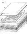
- the composition of the cover plate 2 is shown in FIG. 2, while the base plate 3 is constructed identically to the cover plate 2 with the only exception that the printing paper 15 or 25 is omitted.
- the honeycomb-shaped intermediate layer consists of an ABS plastic with, for example, hexagonally shaped, tubular honeycombs, which are open at the top and bottom, with the top of this intermediate layer with the help of an epoxy adhesive (for example a two-component adhesive Araldit 106) is glued to the underside of the cover plate 2, analogously to how the base plate 3 is glued to the underside of this intermediate view 4 as well.
- an epoxy adhesive for example a two-component adhesive Araldit 106
- a drawing sheet 8 is drawn schematically at a distance from the cover plate 2 in order to show the field lines 9 which arise along the entire surface of the cover plate and are directed perpendicular to the surface of the cover plate 2.
- the drawing sheet 8 is thereby drawn in the direction of the arrows 10 to the surface 5 of the cover plate 2 and adheres there with high adhesive force, the magnitude of the adhesive force depending on the level of the DC voltage generated by a DC voltage generator 6.
- a negative DC voltage of 5000 volts is preferably generated, which is applied to the printing paper 15 shown in FIG. 2 via corresponding connections 7.
- This high voltage is applied to the printing paper 15 shown in FIG. 2, specifically to connection points 16 of the intermeshing comb-shaped conductor tracks 18, 19, which are not shown in detail.
- the conductor tracks 18, 19 are integrated in the multilayer laminate of the cover plate 2 using the screen printing method.
- the carrier layer 13 over the printing paper is based on a condensate melamine + formaldehyde.
- the DC voltage applied creates an electrostatic adhesive force through interaction in the drawing sheet to be held.
- the drawing sheet 8 causes a short line of force. Due to the connection at the negative high voltage, negative ions emerge from the surface 5 of the cover layer 2, which simultaneously neutralize this drawing sheet 8 when the drawing sheet 8 is pulled off.
- the electronics also have space in the drawing board, so that the DC voltage generator 6 itself is integrated in the drawing board.
- the cover layer 11 arranged above the support layer 13 consists of a condensate melamine + formaldehyde, while the support layers 14 arranged below the printing paper 15 consist of a condensate phenol + formaldehyde.
- the distance 17 of the conductor tracks 18, 19 is selected from one another in such a way that there is no internal breakdown in the area of the printing paper 15.
- FIG. 3 shows a further embodiment of a cover plate 12, in which case a printing paper 15 according to FIG. 2 can be integrated there; however, it is also possible to omit the high-voltage printing paper 15 and instead only provide one printing paper 25 with conductor tracks 2 0 , 21 which are designed as resistance heating.
- the same numbers denote the same layers, so that it can be seen that the resistance-heatable printing paper 25 is bound up and down by an equal number of carrier layers 14.
- the top layer of the carrier layer 14 is followed by a further carrier layer 13 with the features described previously with reference to FIG. 2, while the carrier layer 13 is closed at the top by the cover layer 11.
Abstract
Description
Gegenstand der Erfindung ist eine Vorrichtung zur Halterung blattförmiger Gegenstände, insbesondere Zeichenbrett, bestehend aus einem mehrschichtigen Schichtenaufbau aus flachseitig miteinander verbundenen Deck- und Bodenplatten mit dazwischen angeordneten Trägerschichten.The invention relates to a device for holding sheet-like objects, in particular a drawing board, consisting of a multilayer structure comprising flat and interconnected top and bottom plates with carrier layers arranged therebetween.
Der Verwendungsbereich einer Vorrichtung nach der vorliegenden Erfindung bezieht sich auf die Halterung blattförmiger Gegenstände, wie z.B. Papiere, Folien und dergleichen, als Zeichenbrett, als Organisationstafel, als Tischplatte bei einem Flachtisch-Plotter, als Einsatz von Saugwänden in Repro-Kameras, in der Papier- und Textilverarbeitung, z.B. als Bremse, Spreizfläche, etc.The field of use of a device according to the present invention relates to the holding of sheet-like objects, e.g. Papers, foils and the like, as a drawing board, as an organization board, as a table top for a flat table plotter, as a suction wall in repro cameras, in paper and textile processing, e.g. as a brake, spreading surface, etc.
Bei den bisher bekannten Zeichenbrettern bedurfte es aufwendiger mechanischer Halterungen zur Halterung grosser Papierformate, wie z.B. von Zeichenblättern mit dem Forma A 1 oder A O. Nachteil dieser mechanischen Festhaltevorrichtungen war, daß ein ungehindertes Arbeiten nicht möglich war, denn die am Rand angebrachten mechanischen Festhaltevorrichtungen störten beim Zeichnen. Ausserdem bestand bei diesen mechanischen Festhaltevorrichtungen der Nachteil, daß eine Festklemmung des Zeichenpapiers nur am Rand erfolgte, nicht aber in der Mitte. Es konnte dann deshalb vorkommen, daß während des Zeichnens das Zeichenpapier in der Mitte zusammengeschoben, geknickt oder eingerissen wurde. Das gleiche konnte im Bereich der Festhaltevorrichtung am Rande des Zeichenblattes geschehen.With the previously known drawing boards, complex mechanical holders for holding large paper formats, such as e.g. of drawing sheets with the Forma A 1 or A O. The disadvantage of these mechanical holding devices was that unimpeded working was not possible, because the mechanical holding devices attached to the edge interfered with the drawing. In addition, there was the disadvantage with these mechanical holding devices that the drawing paper was only clamped at the edge, but not in the middle. It could then happen that the drawing paper was pushed together, folded or torn in the middle while drawing. The same could happen in the area of the holding device on the edge of the drawing sheet.
Die Erfindung hat sich ausgehend von einer Vorrichtung der eingangs genannten Art die Aufgabe gestellt, eine derartige Vorrichtung so weiterzubilden, daß eine grossflächige Befestigung des blattförmigen Gegenstandes auf dem Zeichenbrett erfolgt, ohne daß es störender, über die Oberfläche des Zeichenbrettes hinausstehender mechanicher Festhaltevorrichtungen bedarf.Starting from a device of the type mentioned at the outset, the invention has the object of developing such a device in such a way that the sheet-like object is fastened over a large area to the drawing board without the need for disruptive mechanical holding devices which protrude beyond the surface of the drawing board.
Zur Lösung der gestellten Aufgabe ist die Erfindung dadurch gekennzeichnet, daß die Halterung des blattförmigen Gegenstandes durch eine elektrostatische Kraft erfolgt, die durch Anlegen einer negativen Gleichspannung an ein in der Deckplatte angeordnetes stromleitendes Druckpapier erzeugt ist.To achieve the object, the invention is characterized in that the sheet-shaped object is held by an electrostatic force which is generated by applying a negative DC voltage to an electrically conductive printing paper arranged in the cover plate.
Wesentliches Merkmal der vorliegenden Erfindung ist also die Halterung des Zeichenblattes mit einer elektrostatischen Kraft, die über die gesamte Fläche des Zeichenbrettes erzeugt wird. Hierdurch wird eine grossflächige, über die Fläche des Zeichenbrettes gesehen gleichmässige Haltekraft auf das Zeichenblatt aufgebracht, das deshalb nicht nur am Rande, sondern im gesamten Auflagebereich fest an der obersten Platte des Zeichenbrettes haftet.An essential feature of the present invention is therefore the holding of the drawing sheet with an electrostatic force that is generated over the entire surface of the drawing board. As a result, a large holding force, as seen across the surface of the drawing board, is applied to the drawing sheet, which therefore not only adheres firmly to the top plate of the drawing board, but also in the entire support area.
Es gibt nun kein Verschieben mehr des Zeichenblattes während des Zeichenvorganges, weil eine grossflächige Haftung über die gesamte Fläche des Zeichenblattes gewährleistet ist.There is no longer any movement of the drawing sheet during the drawing process, because large-area adhesion is guaranteed over the entire area of the drawing sheet.
Durch einen entsprechenden Aufbau der Deck- und der Bodenplatte und der dazwischen angeordneten Zwischenschicht, die aus einer Kunststoff-Wabenstruktur aus dem Kunststoff ABS besteht, ergibt sich eine absolute Parallelität von Deck- und Bodenplatte und eine absolut ebene Deckplatte, so daß wegen der ebenen Auflage Zeichenblätter mit höchster Präzision beschriftet werden können.A corresponding structure of the top and bottom plates and the intermediate layer arranged between them, which consists of a plastic honeycomb structure made of ABS plastic, results in an absolute parallelism of the top and bottom plates and an absolute flat cover plate so that drawing sheets can be labeled with the highest precision because of the flat surface.
Nach dem Gegenstand des Anspruches 2 wird es hierbei bevorzugt, wenn das stromleitende Druckpapier aus einem Alphazellulosepapier besteht, das mit Phenol- und Melaminharz imprägniert ist und das im Sieb- oder Rotationsverfahren mit einer stromleitenden Leiterbahn bedruckt ist.According to the subject matter of
Der erfindungsgemässe Aufbau des Druckpapiers aus den genannten Materialien gewährleistet die Standfähigkeit des Druckes auch bei der nachfolgenden Verpressung, wenn das Druckpapier zwischen entsprechenden Träger- und Deckschichten eingebunden und unter Wärme und hohem Druck verpresst wird. Es kommt zu keinem Ausfliessen und Ausfransen der stromleitenden Leiterbahnen.The structure of the printing paper according to the invention from the materials mentioned ensures the stability of the print even in the subsequent pressing, if the printing paper is bound between the corresponding carrier and cover layers and is pressed under heat and high pressure. There is no leakage and fraying of the conductive conductors.
Es wird hierbei nach dem Gegenstand des Anspruches 3 besonders bevorzugt, wenn die stromleitende Leiterbahn im Siebdruckverfahren aufgebracht ist und aus Graphitfarbe oder Silbernitratfarbe besteht. Als Graphitfarbe wird vorzugsweise das Fabrikat Grapharol 114 verwendet, das auf Acrylatbasis aufgebaut ist und mit Graphitleitpigmenten vermischt ist. Ebenso ist die Verwendung einer Silbernitratfarbe möglich. Beide Farbzusammensetzungen haben den oben genannten Vorteil, nämlich, daß ein Verlaufen und Ausfransen der Leiterbahnen auch bei der Einbindung des Druckpapieres in die vorgesehenen Deck-und Trägerschichten im Warmpressverfahren vermieden wird.According to the subject matter of
Nach dem Gegenstand des Anspruches 4 wird es hierbei bevorzugt, wenn das stromleitende Druckpapier in Richtung zum Zeichenblatt von einer Trägerschicht aus Alphazellulosepapier imprägniert mit Phenol- und Melaminharz und Farbstoff abgedeckt ist. Diese Trägerschicht muss eine relativ hohe Spannungsfestigkeit haben, um einen Durchschlag der Spannung in Richtung zum Zeichenblatt zu vermeiden. Der Zusatz von Farbstoffen erfolgt deshalb, damit das stromleitende Druckpapier in Richtung vom Zeichenblatt her gesehen nicht von oben sichtbar ist. Statt der Verwendung eines Farbstoffes, mit dem die Trägerschicht eingefärbt ist, ist es nach dem Gegenstand des Anspruches 5 auch möglich, daß die Trägerschicht mit einer Druckfolie mit aufgedrucktem Millimeter-Raster verbunden ist, so daß man durch das aufgelegte Zeichenblatt hindurch das Millimeter-Raster sehen kann und dies als Hilfslinie verwenden kann.According to the subject matter of claim 4, it is preferred in this case if the electrically conductive printing paper is impregnated in the direction of the drawing sheet by a carrier layer made of alpha cellulose paper with phenolic and melamine resin and ink fabric is covered. This carrier layer must have a relatively high dielectric strength in order to avoid a breakdown of the voltage in the direction of the drawing sheet. Dyes are added so that the conductive paper is not visible from above when viewed from the drawing sheet. Instead of using a dye with which the carrier layer is colored, it is also possible, according to the subject matter of
Das stromleitende Druckpapier ist nach dem Gegenstand des Anspruches 6 in Richtung zur Bodenplatte von mehreren übereinander geschichteten Trägerschichten abgedeckt, von denen jede aus einem mit Phenolharz imprägnierten Natron-Kraftpapier besteht.The current-conducting printing paper is covered according to the subject matter of
Mit den übereinander geschichteten Trägerschichten, es wird beispielsweise eine Anzahl von 8 gleichartigen Trägerschichten verwendet, ergibt sich die notwendige Biegungssteifigkeit und die notwendige Stromfestigkeit.With the support layers stacked on top of one another, for example a number of 8 support layers of the same type are used, the necessary bending stiffness and the necessary current resistance are obtained.
Die gesamte Deckplatte besteht aus einer Deckschicht, einer darunter angeordneten Trägerschicht, dem darunter folgenden Druckpapier und den unter dem Druckpapier angeordneten Trägerschichten, wird im Heisspressverfahren verpresst, wobei sich eine fertige Dicke von etwa 1,4 mm ergibt.The entire cover plate consists of a cover layer, a support layer arranged underneath, the printing paper below it and the support layers arranged under the printing paper, is pressed using the hot press method, resulting in a finished thickness of approximately 1.4 mm.
Ein Zeichenbrett nach der vorliegenden Erfindung wird gemäss dem Gegenstand des Anspruches 6 aus einer Deckplatte und einer gleichartigen Bodenplatte aufgebaut, wobei die Bodenplatte mit Ausnahme der Verwendung des Druckpapieres identisch wie die Deckplatte aufgebaut ist. Zwischen der Deckplatte und der Bodenplatte befindet sich eine wabenartige Zwischenschicht, wobei die Deckplatte mit ihrer Unterseite mit einem Epoxykleber Araldit 106-Zweikomponenten mit der Oberfläche der Wabenschicht verbunden ist und gleichfalls die Bodenplatte ihrerseits ebenfalls mit der Unterseite der Wabenschicht verbunden ist.A drawing board according to the present invention is constructed according to the subject matter of
Eingangs wurde ausgeführt, daß zur Halterung des Zeichenblattes an das stromleitende Druckpapier eine Hochspannung angelegt wird. Es ist nun zusätzlich möglich, neben der Verwendung eines Hochspannung führenden Druckpapiers ein weiteres Druckpapier in die genannten Schichten einzubetten, das Leiterbahnen in einer solchen Anordnung enthält, daß eine Widerstandsheizung möglich ist. Man kann das Zeichenbrett hierdurch nicht nur mit der entsprechenden Haltevorrichtung versehen, sondern man kann zusätzlich auch noch das Zeichenbrett beheizen, was für manche Anwendungsfälle wichtig ist.At the outset, it was stated that a high voltage is applied to the current-carrying printing paper to hold the drawing sheet. It is now additionally possible, in addition to the use of high-voltage printing paper, to embed another printing paper in the layers mentioned, which contains conductor tracks in such an arrangement that resistance heating is possible. You can not only provide the drawing board with the appropriate holding device, but you can also heat the drawing board, which is important for some applications.
Ebenso ist es möglich, das Hochspannung führende Druckpapier, welches die elektrostatische Haltekraft ausübt, wegzulassen und nur ein heizbares Druckpapier mit entsprechenden Leiterbahnen einzulegen. Es ergibt sich dann ein heizbares Zeichenbrett.It is also possible to omit the high-voltage printing paper, which exerts the electrostatic holding force, and to insert only a heatable printing paper with corresponding conductor tracks. The result is a heatable drawing board.
Der Erfindungsgegenstand der vorliegenden Erfindung ergibt sich nicht nur aus dem Gegenstand der einzelnen Patentansprüche, sondern auch aus der Kombination der einzelnen Patentansprüche untereinander.The subject matter of the present invention results not only from the subject matter of the individual patent claims, but also from the combination of the individual patent claims with one another.
Alle in den Unterlagen offenbarten Angaben und Merkmale, insbesondere die in den Zeichnungen dargestellte räumliche Ausbildung werden als erfindungswesentlich beansprucht, soweit sie einzeln oder in Kombination gegenüber dem Stand der Technik neu sind.All information and features disclosed in the documents, in particular the spatial design shown in the drawings, are claimed as essential to the invention, insofar as they are new compared to the prior art, individually or in combination.
Im folgenden wird die Erfindung an Hand einer lediglich einen Ausführungsweg darstellenden Zeichnung näher erläutert. Hierbei gehen aus der Zeichnung und ihrer Beschreibung weitere erfindungswesentliche Merkmale und Vorteile der Erfindung hervor.The invention is explained in more detail below with the aid of a drawing which represents only one embodiment. Here, further features and advantages of the invention that are essential to the invention emerge from the drawing and its description.
Es zeigen:
- Fig. 1: schematisiert gzeichneter Querschnitt durch ein Zeichenbrett nach der Erfindung mit angelegter Hochspannungsquelle,
- Fig. 2: perspektivische, auseinandergezogene Darstellung des Aufbaus der Deckplatte in einer ersten Ausführungsform,
- Fig. 3: gleiche Darstellung wie Fig. 2 mit einer zweiten Ausführungsform einer Deckplatte.
- 1: schematically drawn cross-section through a drawing board according to the invention with a high-voltage source applied,
- 2: perspective, exploded view of the structure of the cover plate in a first embodiment,
- 3: same representation as FIG. 2 with a second embodiment of a cover plate.
In Fig. 1 ist schematisiert ein Zeichenbrett 1 gezeigt, das aus einer Deckplatte 2, einer wabenförmigen Zwischenschicht 4 und einer Bodenplatte 4 besteht. Die Zusammensetzung der Deckplatte 2 ist in Fig. 2 gezeigt, während die Bodenplatte 3 identisch wie die Deckplatte 2 aufgebaut ist mit der einzigen Ausnahme, daß das Druckpapier 15 bzw. 25 entfällt.In Fig. 1, a drawing board 1 is shown schematically, which consists of a
Die wabenförmige Zwischenschicht besteht aus einem ABS-Kunststoff mit beispielsweise hexagonal geformten, röhrenförmigen Waben, die nach oben und unten durchgehend offen sind, wobei die Oberseite dieser Zwischenschicht mit Hilfe eines Epoxyklebers (z.B. einem Zweikomponentenkleber Araldit 106) mit der Unterseite der Deckplatte 2 verklebt ist, analog wie die Bodenplatte 3 mit der Unterseite dieser Zwischensicht 4 ebenso verklebt ist.The honeycomb-shaped intermediate layer consists of an ABS plastic with, for example, hexagonally shaped, tubular honeycombs, which are open at the top and bottom, with the top of this intermediate layer with the help of an epoxy adhesive (for example a two-component adhesive Araldit 106) is glued to the underside of the
In Fig. 1 ist schematisiert ein Zeichenblatt 8 im Abstand von der Deckplatte 2 gezeichnet, um die Feldlinien 9 zu zeigen, die längs der gesamten Oberfläche der Deckplatte entstehen und senkrecht zur Oberfläche der Deckplatte 2 gerichtet sind. Das Zeichenblatt 8 wird hierdurch in den Pfeilrichtungen 1o zur Oberfläche 5 der Deckplatte 2 hingezogen und haftet dort mit hoher Haftkraft, wobei die Grösse der Haftkraft von der Höhe der Gleichspannung abhängt, die von einem Gleichspannungsgenerator 6 erzeugt wird. Es wird vorzugsweise eine negative Gleichspannung von 5000 Volt erzeugt, die über entsprechende Anschlüsse 7 an das in Fig. 2 gezeigte Druckpapier 15 angelegt wird.In Fig. 1, a
Diese Hochspannung wird auf das in Fig. 2 gezeigte Druckpapier 15 gegeben und zwar auf nicht näher dargestellte Anschlusspunkte 16 der ineinandergreifenden kammleistenförmigen Leiterbahnen 18,19. Die Leiterbahnen 18,19 sind hierbei im Siebdruckverfahren in dem Mehrschichtenlaminat der Deckplatte 2 integriert. Die Trägerschicht 13 über dem Druckpapier basiert auf einem Kondensat Melamin + Formaldehyd. Durch die angelegte Gleichspannung entsteht durch Wechselwirkung in dem zu haltenden Zeichenblatt eine elektrostatische Haftkraft. Das Zeichenblatt 8 bewirkt hierbei einen Kraftlinienkurzschluss. Durch den Anschluss bei der negativen Hochspannung treten negative Ionen aus der Oberfläche 5 der Deckschicht 2 aus, welche beim Abziehen des Zeichenblattes 8 gleichzeitig dieses Zeichenblatt 8 neutralisieren.This high voltage is applied to the
Als Nebeneffekt tritt durch die negativen Ionen eine Verbesserung des Wohnklimas auf.As a side effect, an improvement in the living environment occurs due to the negative ions.
Die Elektronik hat auf Grund ihres hohen Wirkungsgrades (grösser als 90 Prozent) auch im Zeichenbrett Platz, so daß der Gleichspannungsgenerator 6 selbst im Zeichenbrett integriert ist.Because of its high efficiency (greater than 90 percent), the electronics also have space in the drawing board, so that the
Es wird dann nur noch die Netzanschlußschnur nach aussen geführt.Then only the power cord is led outside.
Die über der Trägerschicht 13 angeordnete Deckschicht 11 besteht aus einem Kondensat Melamin + Formaldehyd, während die unterhalb des Druckpapiers 15 angeordnete Trägerschichten 14 aus einem Kondensat Phenol + Formaldehyd bestehen.The
Wichtig ist noch, daß der Abstand 17 der Leiterbahnen 18,19 so voneinander gewählt ist, daß es nicht zu einem inneren Durchschlag im Bereich des Druckpapiers 15 kommt.It is also important that the
Fig. 3 zeigt eine weitere Ausführungsform einer Deckplatte 12, wobei ein Druckpapier 15 nach Fig. 2 dort integriert sein kann; es ist aber ebenso möglich, das hochspannungsführende Druckpapier 15 fortzulassen und stattdessen nur ein Druckpapier 25 mit Leiterbahnen 20,21 vorzusehen, die als Widerstandsheizung ausgebildet sind. Die gleichen Zahlen bezeichnen die gleichen Schichten, so daß ersichtlich ist, daß das widerstandsheizbare Druckpapier 25 nach oben und unten hin durch eine gleiche Anzahl von Trägerschichten 14 eingebunden ist. In Richtung zur Oberfläche 5 hin schliesst sich an die oberste Schicht der Trägerschicht 14 eine weitere Trägerschicht 13 mit den vorher in Bezug auf Fig. 2 beschriebenen Merkmalen an, während die Trägerschicht 13 nach oben durch die Deckschicht 11 abgeschlossen ist.FIG. 3 shows a further embodiment of a
Claims (9)
dadurch gekennzeichnet, daß
die Halterung des blattförmigen Gegenstandes (Zeichenblatt (8) ) durch eine elektrostatische Kraft erfolgt, die durch Anlegen einer negativen Gleichspannung an ein in der Deckplatte (2) angeordnetes stromleitendes Druckpapier (15,25) erzeugt ist.1. Device for holding sheet-like objects, in particular a drawing board, consisting of a multilayered structure comprising flat or interconnected top or bottom plates with carrier layers arranged between them.
characterized in that
the sheet-shaped object (drawing sheet (8)) is held by an electrostatic force which is generated by applying a negative direct voltage to an electrically conductive printing paper (15, 25) arranged in the cover plate (2).
Applications Claiming Priority (2)
| Application Number | Priority Date | Filing Date | Title |
|---|---|---|---|
| DE19813133367 DE3133367A1 (en) | 1981-08-24 | 1981-08-24 | DEVICE FOR HOLDING LEAF-SHAPED ITEMS, IN PARTICULAR DRAWING BOARD OR REGISTRATION PLATE |
| DE3133367 | 1981-08-24 |
Publications (2)
| Publication Number | Publication Date |
|---|---|
| EP0073439A2 true EP0073439A2 (en) | 1983-03-09 |
| EP0073439A3 EP0073439A3 (en) | 1985-11-13 |
Family
ID=6139959
Family Applications (1)
| Application Number | Title | Priority Date | Filing Date |
|---|---|---|---|
| EP82107672A Withdrawn EP0073439A3 (en) | 1981-08-24 | 1982-08-21 | Device for holding sheet-like objects, in particular a drawing board or registration pad |
Country Status (4)
| Country | Link |
|---|---|
| EP (1) | EP0073439A3 (en) |
| JP (1) | JPS5858879A (en) |
| AU (1) | AU554837B2 (en) |
| DE (1) | DE3133367A1 (en) |
Cited By (1)
| Publication number | Priority date | Publication date | Assignee | Title |
|---|---|---|---|---|
| GB2544883A (en) * | 2015-10-27 | 2017-05-31 | Js Design Pro Ltd | Improvements in drawing boards |
Families Citing this family (3)
| Publication number | Priority date | Publication date | Assignee | Title |
|---|---|---|---|---|
| DE4017786C1 (en) * | 1990-06-01 | 1991-10-02 | Lichtenstein Ltd., Gibraltar, Gi | |
| DE4119526A1 (en) * | 1991-06-13 | 1992-12-17 | Lichtenstein Ltd | HV meandering electrode system for electrostatic holding plates - has tracks formed on board with outer tracks receiving HV to cause electrostatic discharge |
| DE4410091C2 (en) * | 1994-03-24 | 2003-01-09 | Helmut Woll | Process for the production of electrostatic adhesive boards |
Citations (10)
| Publication number | Priority date | Publication date | Assignee | Title |
|---|---|---|---|---|
| US2810232A (en) * | 1953-11-12 | 1957-10-22 | Jr Horace Fletcher | Dull finish laminated drawing board cover |
| GB996598A (en) * | 1961-09-04 | 1965-06-30 | Mason & Sons Ltd E N | Improvements in and relating to drawing boards |
| DE1203969B (en) * | 1963-08-16 | 1965-10-28 | F L Moseley Company | Device for holding a sheet material by means of electrostatic attraction |
| US3359469A (en) * | 1964-04-23 | 1967-12-19 | Simco Co Inc | Electrostatic pinning method and copyboard |
| DE1284534B (en) * | 1963-06-26 | 1968-12-05 | ||
| DE1944179A1 (en) * | 1969-08-30 | 1971-03-25 | Watanabe Instr | Electrostatic holding device for recording paper |
| DE2148666A1 (en) * | 1971-09-29 | 1973-04-12 | Addressograph Multigraph | ELECTROSTATIC BLADE HOLDING DEVICE |
| US3916270A (en) * | 1974-05-02 | 1975-10-28 | Tektronix Inc | Electrostatic holddown apparatus |
| DE2503818A1 (en) * | 1975-01-30 | 1976-08-05 | Burger Dierk | Rectangular drawing board - is fitted with drawing paper storage roll and paper winding up roll on opposite sides |
| DE3124316A1 (en) * | 1981-06-20 | 1983-01-05 | Hartmut 8804 Dinkelsbühl Buckel | Drawing apparatus |
Family Cites Families (3)
| Publication number | Priority date | Publication date | Assignee | Title |
|---|---|---|---|---|
| DE1261777B (en) * | 1965-11-20 | 1968-02-22 | Dr Reiner Jordan | Magnetic jig for drawing equipment on drawing tables |
| DE1957657B1 (en) * | 1969-11-17 | 1971-03-25 | Licentia Gmbh | Jig |
| DE3042460A1 (en) * | 1980-11-11 | 1982-06-24 | Artur 5650 Solingen Lange | Electrically heated stand for drafting table - enables use of slow drying inks and contains internal heating resistor |
-
1981
- 1981-08-24 DE DE19813133367 patent/DE3133367A1/en not_active Ceased
-
1982
- 1982-08-21 EP EP82107672A patent/EP0073439A3/en not_active Withdrawn
- 1982-08-24 JP JP14557882A patent/JPS5858879A/en active Pending
- 1982-09-10 AU AU88304/82A patent/AU554837B2/en not_active Expired - Fee Related
Patent Citations (10)
| Publication number | Priority date | Publication date | Assignee | Title |
|---|---|---|---|---|
| US2810232A (en) * | 1953-11-12 | 1957-10-22 | Jr Horace Fletcher | Dull finish laminated drawing board cover |
| GB996598A (en) * | 1961-09-04 | 1965-06-30 | Mason & Sons Ltd E N | Improvements in and relating to drawing boards |
| DE1284534B (en) * | 1963-06-26 | 1968-12-05 | ||
| DE1203969B (en) * | 1963-08-16 | 1965-10-28 | F L Moseley Company | Device for holding a sheet material by means of electrostatic attraction |
| US3359469A (en) * | 1964-04-23 | 1967-12-19 | Simco Co Inc | Electrostatic pinning method and copyboard |
| DE1944179A1 (en) * | 1969-08-30 | 1971-03-25 | Watanabe Instr | Electrostatic holding device for recording paper |
| DE2148666A1 (en) * | 1971-09-29 | 1973-04-12 | Addressograph Multigraph | ELECTROSTATIC BLADE HOLDING DEVICE |
| US3916270A (en) * | 1974-05-02 | 1975-10-28 | Tektronix Inc | Electrostatic holddown apparatus |
| DE2503818A1 (en) * | 1975-01-30 | 1976-08-05 | Burger Dierk | Rectangular drawing board - is fitted with drawing paper storage roll and paper winding up roll on opposite sides |
| DE3124316A1 (en) * | 1981-06-20 | 1983-01-05 | Hartmut 8804 Dinkelsbühl Buckel | Drawing apparatus |
Cited By (1)
| Publication number | Priority date | Publication date | Assignee | Title |
|---|---|---|---|---|
| GB2544883A (en) * | 2015-10-27 | 2017-05-31 | Js Design Pro Ltd | Improvements in drawing boards |
Also Published As
| Publication number | Publication date |
|---|---|
| AU554837B2 (en) | 1986-09-04 |
| DE3133367A1 (en) | 1985-04-25 |
| JPS5858879A (en) | 1983-04-07 |
| AU8830482A (en) | 1984-03-15 |
| EP0073439A3 (en) | 1985-11-13 |
Similar Documents
| Publication | Publication Date | Title |
|---|---|---|
| DE3502990C1 (en) | Multi-layer flock transfer film cutting | |
| WO1999017940A1 (en) | Device made of folded paper that can be fixed to a surface | |
| DE3339828A1 (en) | Electrostatically supported filter element consisting of fibre material, for the separation of particles from gaseous media | |
| EP0073439A2 (en) | Device for holding sheet-like objects, in particular a drawing board or registration pad | |
| DE3916099A1 (en) | METHOD FOR THE PRODUCTION OF DECORATIVE LAYERED COMPRESSION PLATES | |
| EP0243719A2 (en) | Device for fastening an intermediate layer on a cylinder of a rotary printing machine | |
| DE2231086A1 (en) | SURFACE HEATING ELEMENTS | |
| EP0575722A2 (en) | Decorative high-pressure laminate | |
| EP0249717A1 (en) | Changing support for an information medium | |
| DE3415672A1 (en) | Multiple switch | |
| DE3140292C2 (en) | Process for the production of a colored relief on a plate-shaped, fiber-reinforced, plastic-containing decorative body | |
| DE1805204C3 (en) | Arrangement for the production of multicolor prints | |
| EP0634282A1 (en) | Method for preparing an anti-copy film | |
| DE855408C (en) | Flexible planographic printing plate | |
| DE2708910C3 (en) | Multiple, especially endless movements | |
| DE2437596C3 (en) | ||
| DE2822443C2 (en) | Planning element made of transparent, smooth-surfaced, soft adhesive film | |
| DE2536233C3 (en) | Device for pressing plate-shaped! Pressing material in the course of the production of chipboard, fiberboard, plastic laminate panels and the like in package presses | |
| DE1259430B (en) | Process for the production of printed circuits by placing a metal foil on an elastic base | |
| EP0284864B1 (en) | Blotting pad | |
| DE1292625B (en) | Card-shaped recording medium with a window cutout | |
| DE2902690A1 (en) | MULTIPLIFICATION TEMPLATE | |
| DE7834977U1 (en) | BLOCK OF PRINTED SHEETS OR UNPRINTED FOR WRITING OR PAINTING | |
| DE3406121C2 (en) | ||
| DE1623619C (en) | Electrically perforable recording paper |
Legal Events
| Date | Code | Title | Description |
|---|---|---|---|
| PUAI | Public reference made under article 153(3) epc to a published international application that has entered the european phase |
Free format text: ORIGINAL CODE: 0009012 |
|
| AK | Designated contracting states |
Designated state(s): AT BE CH DE FR GB IT LI LU NL SE |
|
| 17P | Request for examination filed |
Effective date: 19840322 |
|
| PUAL | Search report despatched |
Free format text: ORIGINAL CODE: 0009013 |
|
| AK | Designated contracting states |
Designated state(s): AT BE CH DE FR GB IT LI LU NL SE |
|
| STAA | Information on the status of an ep patent application or granted ep patent |
Free format text: STATUS: THE APPLICATION IS DEEMED TO BE WITHDRAWN |
|
| 18D | Application deemed to be withdrawn |
Effective date: 19870303 |
|
| RIN1 | Information on inventor provided before grant (corrected) |
Inventor name: WERDER, HANSRUDOLF |