EP0069922A2 - Control method for automatic transmissions in automotive vehicles - Google Patents
Control method for automatic transmissions in automotive vehicles Download PDFInfo
- Publication number
- EP0069922A2 EP0069922A2 EP82105854A EP82105854A EP0069922A2 EP 0069922 A2 EP0069922 A2 EP 0069922A2 EP 82105854 A EP82105854 A EP 82105854A EP 82105854 A EP82105854 A EP 82105854A EP 0069922 A2 EP0069922 A2 EP 0069922A2
- Authority
- EP
- European Patent Office
- Prior art keywords
- transmission
- accelerator pedal
- function
- transmission ratio
- actuated
- Prior art date
- Legal status (The legal status is an assumption and is not a legal conclusion. Google has not performed a legal analysis and makes no representation as to the accuracy of the status listed.)
- Granted
Links
- 230000005540 biological transmission Effects 0.000 title claims abstract description 51
- 238000000034 method Methods 0.000 title claims abstract description 22
- 230000009467 reduction Effects 0.000 claims abstract description 4
- 230000000694 effects Effects 0.000 abstract description 12
- 230000006870 function Effects 0.000 description 6
- 230000008901 benefit Effects 0.000 description 5
- 238000010586 diagram Methods 0.000 description 4
- 230000008859 change Effects 0.000 description 2
- 230000009471 action Effects 0.000 description 1
- 238000010276 construction Methods 0.000 description 1
- 230000001276 controlling effect Effects 0.000 description 1
- 238000011161 development Methods 0.000 description 1
- 230000018109 developmental process Effects 0.000 description 1
- 238000002347 injection Methods 0.000 description 1
- 239000007924 injection Substances 0.000 description 1
- 238000012423 maintenance Methods 0.000 description 1
- 230000001105 regulatory effect Effects 0.000 description 1
- 230000004044 response Effects 0.000 description 1
- 230000000717 retained effect Effects 0.000 description 1
Images

Classifications
-
- F—MECHANICAL ENGINEERING; LIGHTING; HEATING; WEAPONS; BLASTING
- F16—ENGINEERING ELEMENTS AND UNITS; GENERAL MEASURES FOR PRODUCING AND MAINTAINING EFFECTIVE FUNCTIONING OF MACHINES OR INSTALLATIONS; THERMAL INSULATION IN GENERAL
- F16H—GEARING
- F16H61/00—Control functions within control units of change-speed- or reversing-gearings for conveying rotary motion ; Control of exclusively fluid gearing, friction gearing, gearings with endless flexible members or other particular types of gearing
- F16H61/66—Control functions within control units of change-speed- or reversing-gearings for conveying rotary motion ; Control of exclusively fluid gearing, friction gearing, gearings with endless flexible members or other particular types of gearing specially adapted for continuously variable gearings
-
- B—PERFORMING OPERATIONS; TRANSPORTING
- B60—VEHICLES IN GENERAL
- B60W—CONJOINT CONTROL OF VEHICLE SUB-UNITS OF DIFFERENT TYPE OR DIFFERENT FUNCTION; CONTROL SYSTEMS SPECIALLY ADAPTED FOR HYBRID VEHICLES; ROAD VEHICLE DRIVE CONTROL SYSTEMS FOR PURPOSES NOT RELATED TO THE CONTROL OF A PARTICULAR SUB-UNIT
- B60W10/00—Conjoint control of vehicle sub-units of different type or different function
- B60W10/10—Conjoint control of vehicle sub-units of different type or different function including control of change-speed gearings
-
- B—PERFORMING OPERATIONS; TRANSPORTING
- B60—VEHICLES IN GENERAL
- B60W—CONJOINT CONTROL OF VEHICLE SUB-UNITS OF DIFFERENT TYPE OR DIFFERENT FUNCTION; CONTROL SYSTEMS SPECIALLY ADAPTED FOR HYBRID VEHICLES; ROAD VEHICLE DRIVE CONTROL SYSTEMS FOR PURPOSES NOT RELATED TO THE CONTROL OF A PARTICULAR SUB-UNIT
- B60W10/00—Conjoint control of vehicle sub-units of different type or different function
- B60W10/18—Conjoint control of vehicle sub-units of different type or different function including control of braking systems
-
- B—PERFORMING OPERATIONS; TRANSPORTING
- B60—VEHICLES IN GENERAL
- B60W—CONJOINT CONTROL OF VEHICLE SUB-UNITS OF DIFFERENT TYPE OR DIFFERENT FUNCTION; CONTROL SYSTEMS SPECIALLY ADAPTED FOR HYBRID VEHICLES; ROAD VEHICLE DRIVE CONTROL SYSTEMS FOR PURPOSES NOT RELATED TO THE CONTROL OF A PARTICULAR SUB-UNIT
- B60W30/00—Purposes of road vehicle drive control systems not related to the control of a particular sub-unit, e.g. of systems using conjoint control of vehicle sub-units
- B60W30/18—Propelling the vehicle
- B60W30/1819—Propulsion control with control means using analogue circuits, relays or mechanical links
-
- F—MECHANICAL ENGINEERING; LIGHTING; HEATING; WEAPONS; BLASTING
- F16—ENGINEERING ELEMENTS AND UNITS; GENERAL MEASURES FOR PRODUCING AND MAINTAINING EFFECTIVE FUNCTIONING OF MACHINES OR INSTALLATIONS; THERMAL INSULATION IN GENERAL
- F16H—GEARING
- F16H61/00—Control functions within control units of change-speed- or reversing-gearings for conveying rotary motion ; Control of exclusively fluid gearing, friction gearing, gearings with endless flexible members or other particular types of gearing
- F16H61/21—Providing engine brake control
-
- B—PERFORMING OPERATIONS; TRANSPORTING
- B60—VEHICLES IN GENERAL
- B60W—CONJOINT CONTROL OF VEHICLE SUB-UNITS OF DIFFERENT TYPE OR DIFFERENT FUNCTION; CONTROL SYSTEMS SPECIALLY ADAPTED FOR HYBRID VEHICLES; ROAD VEHICLE DRIVE CONTROL SYSTEMS FOR PURPOSES NOT RELATED TO THE CONTROL OF A PARTICULAR SUB-UNIT
- B60W2540/00—Input parameters relating to occupants
- B60W2540/12—Brake pedal position
-
- F—MECHANICAL ENGINEERING; LIGHTING; HEATING; WEAPONS; BLASTING
- F16—ENGINEERING ELEMENTS AND UNITS; GENERAL MEASURES FOR PRODUCING AND MAINTAINING EFFECTIVE FUNCTIONING OF MACHINES OR INSTALLATIONS; THERMAL INSULATION IN GENERAL
- F16H—GEARING
- F16H59/00—Control inputs to control units of change-speed-, or reversing-gearings for conveying rotary motion
- F16H59/14—Inputs being a function of torque or torque demand
- F16H59/18—Inputs being a function of torque or torque demand dependent on the position of the accelerator pedal
-
- F—MECHANICAL ENGINEERING; LIGHTING; HEATING; WEAPONS; BLASTING
- F16—ENGINEERING ELEMENTS AND UNITS; GENERAL MEASURES FOR PRODUCING AND MAINTAINING EFFECTIVE FUNCTIONING OF MACHINES OR INSTALLATIONS; THERMAL INSULATION IN GENERAL
- F16H—GEARING
- F16H59/00—Control inputs to control units of change-speed-, or reversing-gearings for conveying rotary motion
- F16H59/50—Inputs being a function of the status of the machine, e.g. position of doors or safety belts
- F16H59/54—Inputs being a function of the status of the machine, e.g. position of doors or safety belts dependent on signals from the brakes, e.g. parking brakes
Definitions
- the invention is based on a method according to the type of the main claim and the independent claim 2.
- the known arrangement has the disadvantages that a rigid switching of the switching pattern is carried out as a function of the actuation of the brake pedal, so that the duration and thus the intensity of the brake actuation does not have an effect, and that in addition the response of the motor is insufficiently taken into account. Furthermore, it is not taken into account that the increased braking effect should generally be maintained even if the brake pedal has already been released again, but the accelerator pedal has not yet been actuated again.
- the method according to the invention with the characterizing features of the main claim and the independent claim 2 has the advantage that the duration of the brake application and thus the intensity of the desired braking is taken into account, that over-revving the engine is safely avoided and that the increased engine braking effect is maintained as long until the accelerator pedal is pressed again.
- the method according to the invention can be used with advantage if the transmission ratio of the gear used can be adjusted continuously.
- FIGS. 1 and 2 show block diagrams of two embodiments of devices for carrying out the method according to the invention
- FIG. 3a shows a variant of the circuit diagrams shown in FIGS. 1 and 2 with definition of a narrow area with little accelerator pedal deflection
- Figure 3b is a diagram for explaining the hysteresis switch shown in Figure 3a.
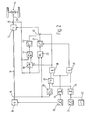
- 10 denotes the motor of a motor vehicle, which is connected via an input shaft 11 to an automatic transmission 12, which in turn is connected to the output 14 via an output shaft 13.
- an engine speed sensor 15 or an output speed sensor 16 are arranged at the output of the engine 10 or the transmission 12.
- an accelerator pedal 20 and a brake pedal 21 are provided, which act on the function of a transmission control unit 23 in a manner to be described.
- the accelerator pedal 20 is connected to the engine 10 and the transmission control unit 23 in a manner known per se, and on the other hand it is also led to a threshold switch 24 which, when the accelerator pedal 20 is released or approximately released, outputs a positive logic output signal and the output signal zero when the accelerator pedal 20 is deflected .
- the brake pedal 21 is connected to a threshold switch 25, the output signal of which is inversely related to the output signal of the threshold switch 24, that is to say that when the brake pedal 21 is not actuated, the output signal is zero and when the brake pedal 25 is actuated positive logic output signal.
- the function of the brake pedal 21 can also be represented by a switch 22 to the extent of interest here, so that the method according to the invention described below can also be controlled purely manually.
- the output signals of the threshold switches 24, 25 are linked in an AND gate 26, the output of which acts on a transmission control unit 27 arranged downstream of the transmission control unit 23.
- the action is such that with a positive output signal of the AND gate 26, the output signal of the transmission control unit 23 is overridden so that there is an increase in the transmission ratio in the transmission 12, which usually depends on the position of the accelerator pedal 20 and the output signal of the Output speed sensor 16 is set.
- a characteristic curve memory 28 is provided which is controlled by the engine speed sensor 15 and by the output speed sensor 16.
- the characteristic curve memory 28 contains a characteristic curve of maximum engine speed depending on the output speed. If the actual engine speed exceeds the characteristic curve specified in the characteristic curve memory 28, an OR gate 29 connected downstream of the characteristic curve memory 28 is driven, the second, inverted input of which is connected to the output of the threshold value switch 25.
- the output of the OR gate 29 is linked to the output of the threshold switch 24 in an AND gate 30, which controls the hold input of a sample-and-hold stage 31, which is arranged between the translation controller 27 and the transmission 12 .
- FIG. 2 The further device shown in FIG. 2 for carrying out a method according to the invention is largely of the same construction as that shown in FIG. 1, so that the same reference numerals are used.
- a sample-and-hold stage 40 is provided which is controlled by the signal of the output speed sensor 16 and whose hold input is in turn connected to the output of the AND gate 30. At the same time, this controls a changeover switch 43, by means of which the control input of the transmission 12 can be switched from the transmission control 27 to the series connection of a comparator 41 and a controller 42, which are connected downstream of the sample-and-hold stage 40.
- the comparator 41 is controlled at its other input by the output speed sensor 16.
- the driver had only the choice between an operation with a high braking effect and the normal driving program with a very low engine braking effect.
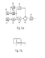
- a method variant can be used, which is illustrated below using the device according to FIG. 3a and the diagram according to FIG. 3b.
- the accelerator pedal 20 is followed by a hysteresis threshold switch 24a instead of a simple threshold switch 24.
- the output signal of the accelerator pedal 20 is fed to a range switch 50, which then emits a positive output signal when the input signal is in a certain narrow range, which is congruent with the hysteresis width of the hysteresis threshold switch 24a.
- the output signals from range switch 50 and hysteresis threshold switch 24a are linked in a further AND gate 51, the output of which is led to the control input of an adjustment stage 52, which is connected between AND gate 26 and translation control 27.
- the hysteresis threshold switch 24a has a characteristic curve as shown in FIG. 3b.
- the method according to the invention described above can be used with particular advantage if the transmission 12 is a continuously variable transmission, since quasi-continuous control is then possible and the transmission ratio can always be adjusted to the extent required by the current driving conditions and the driver's wishes and is desired.
Landscapes
- Engineering & Computer Science (AREA)
- Mechanical Engineering (AREA)
- General Engineering & Computer Science (AREA)
- Chemical & Material Sciences (AREA)
- Combustion & Propulsion (AREA)
- Transportation (AREA)
- Automation & Control Theory (AREA)
- Control Of Transmission Device (AREA)
- Control Of Driving Devices And Active Controlling Of Vehicle (AREA)
Abstract
Es wird ein Verfahren zum Steuern von automatischen Getrieben in Kraftfahrzeugen vorgeschlagen, bei dem das Übersetzungsverhältnis des Getriebes (12) in Abhängigkeit von der Betätigung eines Bremsorganes (21) erhöht wird. Dabei wird das Übersetzungsverhältnis solange erhöht, bis das Bremsorgan (21) nicht mehr betätigt wird oder die Motordrehzahl eine vorgegebene Kennlinie in Abhängigkeit von der Abtriebsdrehzahl überschreitet. Sobald dies der Fall ist wird entweder das gerade eingestellte Übersetzungsverhältnis gespeichert und eine Verminderung unterdrückt, bis das Fahrpedal (20) erneut betätigt wird oder es wird die gerade eingenommene Fahrgeschwindigkeit des Kraftfahrzeuges gespeichert und das Übersetzungsverhältnis so eingestellt, daß die Fahrgeschwindigkeit beibehalten wird, bis das Fahrpedal (20) erneut betätigt wird. Auf diese Weise wird die Motorbremswirkung bei gewolltem Bremsen mit ausgenutzt.A method for controlling automatic transmissions in motor vehicles is proposed, in which the transmission ratio of the transmission (12) is increased as a function of the actuation of a braking member (21). The transmission ratio is increased until the braking member (21) is no longer actuated or the engine speed exceeds a predetermined characteristic curve as a function of the output speed. As soon as this is the case, either the gear ratio which has just been set is stored and a reduction is suppressed until the accelerator pedal (20) is actuated again, or the driving speed of the motor vehicle which has just been taken is stored and the gear ratio is set in such a way that the driving speed is maintained until that Accelerator pedal (20) is operated again. In this way, the engine braking effect is used when braking intentionally.
Description
Die Erfindung geht aus von einem Verfahren nach der Gattung des Hauptanspruches und des nebengeordneten Anspruches 2.The invention is based on a method according to the type of the main claim and the independent claim 2.
Es ist bekannt, bei automatischen Stufengetrieben in Kraftfahrzeugen die Umschaltpunkte des der Getriebesteuerung zugrundeliegenden Schaltmusters dann zu verändern, wenn das Bremspedal betätigt wird. Hierdurch wird erreicht, daß bei Betätigung des Bremspedals eine erhöhte Motorbremswirkung dadurch ausgenutzt wird, daß ein Hochschalten unterdrückt oder gar rückgeschaltet wird. Eine derartige Vorrichtung ist in der DE-AS 19 54 757 beschrieben.It is known to change the changeover points of the shift pattern on which the transmission control is based in automatic step transmissions in motor vehicles when the brake pedal is actuated. This ensures that an increased engine braking effect is exploited when the brake pedal is actuated in that an upshift is suppressed or even downshifted. Such a device is described in DE-AS 19 54 757.
Die bekannte Anordnung hat jedoch den Nachteile daß starrin Abhängigkeit von der Betätigung des Bremspedals eine feste Umschaltung des Schaltmusters vorgenommen wird, so daß die Dauer und damit die Intensität der Bremsbetätigung sich nicht auswirkt und daß darüber hinaus die Reaktion des Motors unzureichend berücksichtigt wird. Weiterhin bleibt unberücksichtigt, daß im allgemeinen die'erhöhte Bremswirkung auch dann beibehalten werden soll, wenn das Bremspedal bereits wieder gelöst wurde, das Fahrpedal jedoch noch nicht wieder betätigt wird.However, the known arrangement has the disadvantages that a rigid switching of the switching pattern is carried out as a function of the actuation of the brake pedal, so that the duration and thus the intensity of the brake actuation does not have an effect, and that in addition the response of the motor is insufficiently taken into account. Furthermore, it is not taken into account that the increased braking effect should generally be maintained even if the brake pedal has already been released again, but the accelerator pedal has not yet been actuated again.
Das erfindungsgemäße Verfahren mit den kennzeichnenden Merkmalen des Hauptanspruches und des nebengeordneten Anspruches 2 hat demgegenüber den Vorteil, daß die Dauerder Bremsbetätigung und damit die Intensität der gewünschten Bremsung mit berücksichtigt wird, daß ein Überdrehen des Motors sicher vermieden wird und daß die erhöhte Motorbremswirkung solange beibehalten wird, bis das Fahrpedal erneut betätigt wird.The method according to the invention with the characterizing features of the main claim and the independent claim 2 has the advantage that the duration of the brake application and thus the intensity of the desired braking is taken into account, that over-revving the engine is safely avoided and that the increased engine braking effect is maintained as long until the accelerator pedal is pressed again.
Durch die in den Unteransprüchen aufgeführten Maßnahmen sind vorteilhafte Weiterbildungen der in den nebengeordneten Ansprüchen angegebenen Verfahren möglich.The measures listed in the subclaims enable advantageous developments of the methods specified in the independent claims.
So kann durch Festlegen eines schmalen Bereiches geringer Fahrpedalauslenkung bewirkt werden, daß beim erneuten Betätigen des Fahrpedales nach einem Bremsvorgang die Bremswirkung wenigstens in geringem Umfang aufrechterhalten wird, wenn das Fahrpedal nur geringfügig betätigt wird.For example, by setting a narrow range of slight accelerator pedal deflection, it can be achieved that when the accelerator pedal is pressed again after a braking operation, the braking effect is maintained at least to a small extent if the accelerator pedal is actuated only slightly.
Weiterhin läßt sich das erfindungsgemäße Verfahren mit Vorteil dann einsetzen, wenn das Übersetzungsverhältnis des verwendeten Getriebes stufenlos einstellbar ist.Furthermore, the method according to the invention can be used with advantage if the transmission ratio of the gear used can be adjusted continuously.
Weitere Vorteile ergeben sich aus der Beschreibung und der beigefügten Zeichnung.Further advantages result from the description and the attached drawing.
Ausführungsbeispiele der Erfindung sind in den Zeichnungen dargestellt und in der nachfolgenden Beschreibung näher erläutert. Es zeigen: Figuren 1 und 2 Blockschaltbilder von zwei Ausführungsformen von Vorrichtungen zur Durchführung des erfindungsgemäßen Verfahrens; Figur 3a eine Variante zu den in Figur 1 und 2 dargestellten Schaltbildern mit Definition eines schmalen Bereiches geringer Fahrpedalauslenkung; Figur 3b ein Diagramm zur Erläuterung des in Figur 3a dargestellten Hystereseschalters.Embodiments of the invention are shown in the drawings and explained in more detail in the following description. 1 and 2 show block diagrams of two embodiments of devices for carrying out the method according to the invention; FIG. 3a shows a variant of the circuit diagrams shown in FIGS. 1 and 2 with definition of a narrow area with little accelerator pedal deflection; Figure 3b is a diagram for explaining the hysteresis switch shown in Figure 3a.
In Figur 1 ist mit 10 der Motor eines Kraftfahrzeuges bezeichnet, der über eine Antriebswelle 11 mit einem automatischen Getriebe 12 in Verbindung steht, das seinerseits über eine Abtriebswelle 13 mit dem Abtrieb 14 in Verbindung steht. Am Ausgang des Motors 10 bzw. des Getriebes 12 sind ein Motordrehzahl-Geber 15 bzw. ein Abtriebsdrehzahl-Geber 16 angeordnet.In FIG. 1, 10 denotes the motor of a motor vehicle, which is connected via an
Zur Steuerung des automatischen Getriebes 12 sind ein Fahrpedal 20 und ein Bremspedal 21 vorgesehen, die in noch zu beschreibender Weise auf die Funktion einer Getriebesteuereinheit 23 einwirken. Das Fahrpedal 20 ist dabei einmal in an sich bekannter Weise mit dem Motor 10 und der Getriebesteuereinheit 23 verbunden, zum anderen ist es auch auf einen Schwellwertschalter 24 geführt, der bei gelöstem oder näherungsweise gelöstem Fahrpedal 20 ein positives logisches Ausgangssignal und bei ausgelenktem Fahrpedal 20 das Ausgangssignal Null abgibt.To control the
Das Bremspedal 21 ist neben seiner üblichen Funktion zur Steuerung des Bremsorganes des Kraftfahrzeuges mit einem Schwellwertschalter 25 verbunden, dessen Ausgangssignal sich invers zum Ausgangssignal des Schwellwertschalters 24 verhält, d.h., daß bei nicht betätigtem Bremspedal 21 das Ausgangssignal Null ist und sich bei betätigtem Bremspedal 25 ein positives logisches Ausgangssignal einstellt. Es versteht sich, daß eich die Funktion des Bremspedales 21 im hier interessierenden Umfang auch durch einen Schalter 22 darstellen läßt, so daß die nachstehend beschriebenen erfindungsgemäßen Verfahren auch rein manuell steuerbar sind.In addition to its usual function for controlling the braking element of the motor vehicle, the
Die Ausgangssignale der Schwellwertschalter 24, 25 sind in einem UND-Gatter 26 verknüpft, dessen Ausgang auf eine der Getriebesteuereinheit 23 nachgeordnete Übersetzungssteuerung 27 einwirkt. Die Einwirkung ist dabei derart, daß bei einem positiven Ausgangssignal des UND-Gatters 26 das Ausgangssignal der Getriebesteuereinheit 23 so übersteuert wird, daß sich im Getriebe 12 eine Erhöhung des Übersetzungsverhältnisses ergibt, das üblicherweise in Abhängigkeit von der Stellung des Fahrpedals 20 und vom Ausgangssignal des Abtriebsdrehzahl-Gebers 16 eingestellt wird.The output signals of the
Weiterhin ist ein Kennlinienspeicher 28 vorgesehen, der vom Motordrehzahl-Geber 15 und vom Abtriebsdrehzahl-Geber 16 angesteuert wird. Der Kennlinienspeicher 28 enthält eine Kennlinie maximaler Motordrehzahl in Abhängigkeit von der Abtriebsdrehzahl. Überschreitet die tatsächliche Motordrehzahl die im Kennlinienspeicher 28 vorgegebene Kennlinie, wird ein dem Kennlinienspeicher 28 nachgeschaltetes ODER-Gatter 29 angesteuert, dessen zweiter, invertierter Eingang mit dem Ausgang des Schwellwertschalters 25 verbunden ist. Der Ausgang des ODER-Gatters 29 ist mit dem Ausgang des Schwellwertschalters 24 in einem UND-Gatter 30 verknüpft, das den Hold-Eingang eines Sample-and-Hold-Stufe 31 ansteuert, die zwischen der Übersetzungssteuerung 27. und dem Getriebe 12 angeordnet ist.Furthermore, a
Ein erstes erfindungsgemäßes Verfahren soll nun anhand der Vorrichtung gemäß Figur 1 veranschaulicht werden:
- Im üblichen Fahrbetrieb wird die Übersetzung des
Getriebes 12 durch dieGetriebesteuereinheit 23 in Abhängigkeit von der Auslenkung des Fahrpedals 20 (Lastinformation) und dem Ausgangssignal des Abtriebsdrehzahl-Gebers 16 (Fahrgeschwindigkeitsinformation) gesteuert. Es versteht sich dabei, daß auch andere bekannte Steuerarten für dieGetriebesteuereinheit 23 verwendet werden können, insbesondere kann die Lastinformation auch auf andere Weise als aus der Stellung desFahrpedals 20 ermittelt werden, beispielsweise aus der Stellung einer Drosselklappe, eines Einspritzpumpenreglers und dgl.
- In normal driving, the transmission of the
transmission 12 is controlled by thetransmission control unit 23 as a function of the deflection of the accelerator pedal 20 (load information) and the output signal of the output speed sensor 16 (driving speed information). It goes without saying that other known control types can be used for thetransmission control unit 23, in particular the load information can also be determined in a manner other than from the position of theaccelerator pedal 20, for example from the position of a throttle valve, an injection pump regulator and the like.
Wird nun das Fahrpedal 20 gelöst und das Bremspedal 21 betätigt, erscheinen an den Ausgängen der Schwellwertschalter 24, 25 positive Signale und das UND-Gatter 26 wird durchgesteuert. Dies bewirkt eine Ansteuerung der Übersetzungssteuerung 27 mit der Wirkung, daß das Übersetzungsverhältnis des Getriebes 12 erhöht wird. Hierdurch ergibt sich eine Erhöhung der Motordrehzahl und damit eine erhöhte Motorbremswirkung. Gleichzeitig wird der eine Eingang des UND-Gatters 30 vom Ausgang des Schwellwertschalters 24 positiv angesteuert. Das UND-Gatter 30 ist damit für ein positives Signal an seinem anderen Eingang durchlässig. Diese positive Signal entsteht dann, wenn entweder das Bremspedal gelöst wird (invertierender Eingang des ODER-Gatters 29) oder wenn die Motordrehzahl die im Kennlinienspeicher 28 vorgegebene Kennlinie überschreitet (nicht invertierender Eingang des ODER-Gatters 29). Sobald also eine dieser beiden Bedingungen erreicht ist, d.h. entweder das Fahrpedal gelöst wird oder ein Überdrehen des Motors droht, wird das UND-Gatter 30 durchgesteuert und die gerade eingenommene, von der Übersetzungssteuerung 27 vorgegebene Getriebeübersetzung wird in der Sample-and-Hold-Stufe 31 festgehalten. Dieses Festhalten des Übersetzungsverhältnisses wird nun solange aufrechterhalten, bis das UND-Gatter 30 durch ein 0-Signal vom Schwellwertschalter 24 wieder gesperrt wird, was dann der Fall ist, wenn das Fahrpedal 20 überhaupt bzw. um einen bestimmten Mindestbetrag ausgelenkt wurde, je nachdem wie der Schwellwert in der Schwellwertstufe 24 festgelegt ist. Dies bedeutet insgesamt, daß nach Wiederbetätigen des Fahrpedals 20 sowohl die Übersetzungssteuerung 27 wie auch die Sample-and-Hold-Stufe 31 außer Funktion treten, so daß sich wieder eine übliche Betätigung des Getriebes 12 in Abhängigkeit von den obengenannten Fahrzeugparametern einstellt.If the
Die in Figur 2 dargestellte weitere Vorrichtung zur Durchführung eines erfindungsgemäßen Verfahrens ist weitgehend gleich aufgebaut wie die in Figur 1 dargestellte, so daß gleiche Bezugszeichen verwendet sind.The further device shown in FIG. 2 for carrying out a method according to the invention is largely of the same construction as that shown in FIG. 1, so that the same reference numerals are used.
Im Unterschied zur Anordnung gemäß Figur 1 ist bei der gemäß Figur 2 jedoch eine Sample-and-Hold-Stufe 40 vorgesehen, die von dem Signal des Abtriebsdrehzahl-Gebers 16 angesteuert wird und deren Hold-Eingang wiederum mit dem Ausgang des UND-Gatters 30 verbunden ist. Dieser steuert gleichzeitig einen Umschalter 43, durch den der Steuereingang des Getriebes 12 von der Übersetzungssteuerung 27 auf die Reihenschaltung eines Vergleichers 41 und eines Reglers 42 umschaltbar ist, die der Sample-and-Hold-Stufe 40 nachgeschaltet sind. Der Vergleicher 41 wird dabei an seinem anderen Eingang vom Abtriebsdrehzahl-Geber 16 angesteuert.In contrast to the arrangement according to FIG. 1, the According to FIG. 2, however, a sample-and-
Das weitere erfindungsgemäße Verfahren soll nun anhand der Anordnung gemäß Figur 2 erläutert werden:
- Wie bei dem oben beschriebenen ersten Verfahren wird bei Lösen des
Fahrpedals 20 und Betätigen desBremspedals 21 über das UND-Gatter 26 und dieÜbersetzungssteuerung 27 eine Erhöhung des Übersetzungsverhältnisses desGetriebes 12 bewirkt, da zu diesem Zeitpunkt derUmschalter 43 in der in Figur 2 eingezeichneten Stellung ist. Wird nun jedoch dasBremspedal 21 wieder gelöst oder überschreitet die Motordrehzahl die in demKennlinienspeicher 28 vorgegebene Kennlinie, wird über das ODER-Gatter 29 und das UND-Gatter 30 derUmschalter 43 umgelegt und gleichzeitig in der Sample-and Hold-Stufe 40 der Augenblickswert des Abtriebsdrehzahl-Gebers 16, entsprechend der Fahrgeschwindigkeit des Kraftfahrzeuges, verrastet. Dieser Augenblickswert der Fahrgeschwindigkeit wird imVergleicher 41 mit der tatsächlichen Fahrgeschwindigkeit verglichen und über denRegler 42 wird in Abhängigkeit von der Abweichung dieser beiden Größen dasGetriebe 12 in der Weise nachgeregelt, daß der Augenblickswert der Fahrgeschwindigkeit im Augenblick der Umschaltung desUmschalters 43 erhalten bleibt, d.h., daß das Ausgangssignal desVergleichers 41 auf Null geregelt wird. Durch diese Vorgehensweise ergibt sich insgesamt bei Einleitung eines Bremsvorganges zunächst eine schnelle Erhöhung der Motordrehzahl bei konstanter Fahrgeschwindigkeit, wobei bei Überschreiten der vorgegebenen zulässigen Motordrehzahl die nunmehr hohe Motorbremswirkung für den Bremsvorgang und damit die Verminderung der Fahrgeschwindigkeit zur Verfügung steht.
- As in the first method described above, when the
accelerator pedal 20 is released and thebrake pedal 21 is actuated via theAND gate 26 and thetransmission control 27, the transmission ratio of thetransmission 12 is increased, since at this point thechangeover switch 43 is shown in FIG Position is. However, if thebrake pedal 21 is released again or the engine speed exceeds the characteristic curve specified in thecharacteristic curve memory 28, theswitch 43 is flipped via theOR gate 29 and theAND gate 30 and at the same time in the sample-and-hold stage 40 the instantaneous value of theoutput speed sensor 16, locked according to the driving speed of the motor vehicle. This instantaneous value of the vehicle speed is compared in thecomparator 41 with the actual vehicle speed and, depending on the deviation of these two variables, thetransmission 12 is readjusted by thecontroller 42 in such a way that the instantaneous value of the vehicle speed is retained when theswitch 43 is switched over, ie that the output signal of the Ver 41 is regulated to zero. This procedure initially results in a rapid increase in the engine speed at a constant driving speed when a braking operation is initiated, with the now high engine braking effect for the braking operation and thus the reduction in driving speed being available when the predetermined permissible engine speed is exceeded.
Bei den vorab beschriebenen erfindungsgemäßen Verfahren hatte der Fahrer nur die Wahl zwischen einem Betrieb mit hoher Bremswirkung und dem normalen Fahrprogramm mit sehr geringer Motorbremswirkung. Um diese Verfahren zu erweitern, kann eine Verfahrensvariante verwendet werden, die nachstehend anhand der Vorrichtung gemäß Figur 3a und dem Diagramm gemäß Figur 3b veranschaulicht wird.In the method according to the invention described above, the driver had only the choice between an operation with a high braking effect and the normal driving program with a very low engine braking effect. In order to expand these methods, a method variant can be used, which is illustrated below using the device according to FIG. 3a and the diagram according to FIG. 3b.
Dabei ist dem Fahrpedal 20 statt eines einfachen Schwellwertschalters 24 ein Hysterese-Schwellwertschalter 24a nachgeordnet. Parallel dazu ist das Ausgangssignal des Fahrpedals 20 auf einen Bereichsschalter 50 geführt, der dann ein positives Ausgangssignal abgibt, wenn das Eingangssignal in einem bestimmten schmalen Bereich liegt, der deckungsgleich mit der Hysteresebreite des Hysterese-Schwellwertschalters 24a ist. Die Ausgangssignale von Bereichsschalter 50 und Hysterese-Schwellwertschalter 24a sind in einem weiteren UND-Gatter 51 verknüpft, dessen Ausgang auf den Steuereingang einer Verstellstufe 52 geführt ist, die zwischen das UND-Gatter 26 und die Übersetzungssteuerung 27 geschaltet ist. Der Hysterese-Schwellwertschalter 24a hat dabei eine Kennlinie, wie sie in Figur 3b dargestellt ist. Bei gelöstem Fahrpedal 20 ergibt sich dabei ein positives Ausgangssignal, das solange beibehalten wird, bis das Fahrpedal 20 über den Lastwert L2 ausgelenkt wurde, wonach sich ein Ausgangssignal Null ergibt. Wird nun das Fahrpedal 20 wieder gelöst, schaltet der Hysterese-Schwellwertschalter 24a erst dann wieder auf ein positives Ausgangssignal, wenn der Lastwert L1 unterschritten wurde, der kleiner als L2 ist. Hierdurch wird ein Bereich geringer Fahrpedalauslenkung, nämlich der zwischen L1 und L2 festgelegt, in dem vermutet werden kann, daß der Fahrer noch eine gewisse begrenzte Motorbremswirkung wünscht.The
Für das weitere erfindungsgemäße Verfahren ergibt sich damit zunächst keine Änderung, da bei gelöstem Fahrpedal 20 der Bereichsschalter 50 das Ausgangssignal Null abgibt und das UND-Gatter 51 damit gesperrt ist und die Verstellstufe 52 außer Funktion setzt, so daß das Signal des UND-Gatters 26 unverändert an die Übersetzungssteuerung 27 weiteregeleitet wird. Wird nun bei gelöstem Bremspedal 21 und damit gesperrtem UND-Gatter 26 das Fahrpedal 20 wieder ausgelenkt, bleibt das positive Ausgangssignal am Hysterese-Schwellwertschalter 24a stehen, bis der Lastwert L2 erreicht ist. Dabei wird im Bereich L1 bis L2 das UND-Gatter 51 durchgesteuert, so daß die Verstellstufe 52 in diesem Bereich angesteuert wird, die über die Übersetzungssteuerung 27 eine Verminderung des Übersetzungsverhältnisses des Getriebes 12 nur um einen bestimmten Betrag zuläßt. Erst wenn das Fahrpedal 20 wieder über den Wert L2 hinaus ausgelenkt wurde, wird das UND-Gatter 51 wiederum wegen des Bereichsschalters 50 gesperrt, so daß das Getriebe 12 in den üblichen Fahrbetrieb eines aztomatischen Stufengetriebes gelangt.There is initially no change for the further method according to the invention, since when the
Die vorstehend beschriebenen erfindungsgemäßen Verfahren lassen sich mit besonderem Vorteil dann einsetzen, wenn das Getriebe 12 ein stufenlos verstellbares Getriebe ist, da dann eine quasikontinuierliche Regelung möglich ist und das Übersetzungsverhältnis immer gerade soweit verstellt werden kann, wie dies nach den gegenwärtigen Fahrbedingungen und dem Fahrerwunsch erforderlich und gewünscht ist.The method according to the invention described above can be used with particular advantage if the
Claims (4)
Priority Applications (1)
| Application Number | Priority Date | Filing Date | Title |
|---|---|---|---|
| AT82105854T ATE25360T1 (en) | 1981-07-15 | 1982-07-01 | METHOD OF CONTROLLING AUTOMATIC TRANSMISSIONS IN MOTOR VEHICLES. |
Applications Claiming Priority (4)
| Application Number | Priority Date | Filing Date | Title |
|---|---|---|---|
| DE3127931 | 1981-07-15 | ||
| DE3127931 | 1981-07-15 | ||
| DE19813139985 DE3139985A1 (en) | 1981-07-15 | 1981-10-08 | METHOD FOR CONTROLLING AUTOMATIC TRANSMISSIONS IN MOTOR VEHICLES |
| DE3139985 | 1981-10-08 |
Publications (3)
| Publication Number | Publication Date |
|---|---|
| EP0069922A2 true EP0069922A2 (en) | 1983-01-19 |
| EP0069922A3 EP0069922A3 (en) | 1984-08-29 |
| EP0069922B1 EP0069922B1 (en) | 1987-02-04 |
Family
ID=25794606
Family Applications (1)
| Application Number | Title | Priority Date | Filing Date |
|---|---|---|---|
| EP82105854A Expired EP0069922B1 (en) | 1981-07-15 | 1982-07-01 | Control method for automatic transmissions in automotive vehicles |
Country Status (3)
| Country | Link |
|---|---|
| US (1) | US4501170A (en) |
| EP (1) | EP0069922B1 (en) |
| DE (2) | DE3139985A1 (en) |
Cited By (5)
| Publication number | Priority date | Publication date | Assignee | Title |
|---|---|---|---|---|
| EP0180916A1 (en) * | 1984-10-31 | 1986-05-14 | Shimadzu Corporation | Deceleration control system for automobiles |
| DE3542624A1 (en) * | 1985-12-03 | 1987-06-04 | Michael Meyerle | Control device for an infinitely adjustable gear system for motor vehicles |
| GB2192032A (en) * | 1985-07-08 | 1987-12-31 | Nissan Motor | Control device for transmission |
| EP0280757A1 (en) * | 1987-03-06 | 1988-09-07 | Michael Meyerle | Control system for a continuously variable gearbox for motor vehicles |
| GB2282861A (en) * | 1993-10-15 | 1995-04-19 | Lucas Ind Plc | Methods and systems for controlling automatic transmission systems to allow engine braking |
Families Citing this family (12)
| Publication number | Priority date | Publication date | Assignee | Title |
|---|---|---|---|---|
| DE3334718A1 (en) * | 1983-09-26 | 1985-04-04 | Wabco Westinghouse Fahrzeugbremsen GmbH, 3000 Hannover | TRANSMISSION CONTROL FOR A ROAD VEHICLE |
| JPS6069355A (en) * | 1983-09-26 | 1985-04-20 | Honda Motor Co Ltd | Control device of speed change gear with subspeed change gear for vehicle |
| DE3341652A1 (en) * | 1983-11-18 | 1985-06-05 | Dr.Ing.H.C. F. Porsche Ag, 7000 Stuttgart | METHOD AND DEVICE FOR CONTROLLING A CLUTCH GEAR UNIT |
| DE3560253D1 (en) * | 1984-02-23 | 1987-07-23 | Knorr Bremse Ag | Driver brake valve |
| JPS63167162A (en) * | 1986-12-27 | 1988-07-11 | Isuzu Motors Ltd | Control device for electronic control automatic transmission |
| DE3922040A1 (en) * | 1989-07-05 | 1991-01-17 | Porsche Ag | METHOD AND DEVICE FOR CONTROLLING AN AUTOMATIC GEARBOX |
| DE19755076C2 (en) | 1997-12-11 | 2000-05-31 | Zahnradfabrik Friedrichshafen | Automatic transmission with downshift function |
| EP1013497B1 (en) * | 1998-12-24 | 2006-05-10 | Eaton Corporation | Automated transmission downshift control |
| DE19916637C1 (en) * | 1999-04-13 | 2000-11-23 | Siemens Ag | Method for controlling the drive train of a motor vehicle and drive train control of a motor vehicle |
| DE19952781A1 (en) * | 1999-11-03 | 2001-06-13 | Daimler Chrysler Ag | Method for braking a vehicle |
| KR100352505B1 (en) * | 2000-09-06 | 2002-09-16 | 하태환 | Break system of automobile have semi automatic transmission |
| JP4438733B2 (en) * | 2005-10-26 | 2010-03-24 | ソニー株式会社 | Electronic device and electronic device control method |
Citations (6)
| Publication number | Priority date | Publication date | Assignee | Title |
|---|---|---|---|---|
| DE1954757A1 (en) * | 1968-10-30 | 1970-07-02 | Nissan Motor | Automobile automatic transmission control system |
| US3684066A (en) * | 1969-10-08 | 1972-08-15 | Toyota Motor Co Ltd | Automatic shift control system for automatic transmission |
| DE2165707A1 (en) * | 1971-02-08 | 1972-08-31 | Nissan Motor Co. Ltd., Yokohama (Japan) | Control system for an automatic power transmission system |
| FR2305313A1 (en) * | 1975-03-26 | 1976-10-22 | Bonabel Robert | Automatic transmission vehicle engine braking system - has relay closed to cause gear change on brake pedal application |
| FR2311679A1 (en) * | 1975-05-21 | 1976-12-17 | Daimler Benz Ag | CONTROL SYSTEM FOR VEHICLES, FOR EXAMPLE FOR UTILITY VEHICLES AND PASSENGER CARS |
| GB2058257A (en) * | 1979-09-12 | 1981-04-08 | Bosch Gmbh Robert | Control apparatus for a stepless transmission |
Family Cites Families (13)
| Publication number | Priority date | Publication date | Assignee | Title |
|---|---|---|---|---|
| FR1600304A (en) * | 1968-12-31 | 1970-07-20 | ||
| FR2148728A5 (en) * | 1971-07-30 | 1973-03-23 | Peugeot & Renault | |
| JPS4926929A (en) * | 1972-07-12 | 1974-03-09 | ||
| DE2329364A1 (en) * | 1973-06-08 | 1975-01-02 | Bosch Gmbh Robert | AUTOMATIC TRANSMISSION FOR MOTOR VEHICLES |
| JPS50139269A (en) * | 1974-04-25 | 1975-11-07 | ||
| JPS5259265A (en) * | 1975-11-12 | 1977-05-16 | Nissan Motor Co Ltd | Automatic transmission with downshift maintaining mechanism |
| DE2714559C3 (en) * | 1977-04-01 | 1979-09-13 | Robert Bosch Gmbh, 7000 Stuttgart | Device for controlling step gears in motor vehicles |
| DE2738914C2 (en) * | 1977-08-29 | 1982-05-06 | Robert Bosch Gmbh, 7000 Stuttgart | Method for shifting multi-step transmissions in motor vehicles |
| DE2742032A1 (en) * | 1977-09-19 | 1979-03-29 | Bosch Gmbh Robert | METHOD AND DEVICE FOR ADJUSTING THE OPERATING FORCE OF GEAR COMPONENTS IN STEPPED GEARS |
| DE2811574A1 (en) * | 1978-03-17 | 1979-09-27 | Bosch Gmbh Robert | DEVICE FOR THE CONTROL OF A DRIVE MOTOR-GEAR UNIT OF A MOTOR VEHICLE |
| JPS5827421B2 (en) * | 1978-07-31 | 1983-06-09 | 日産自動車株式会社 | Shift timing control device for automatic transmission |
| JPS5833427B2 (en) * | 1979-03-14 | 1983-07-19 | トヨタ自動車株式会社 | Vehicle transmission switching control device |
| JPS6010223B2 (en) * | 1979-07-09 | 1985-03-15 | 日産自動車株式会社 | Shift control device for automatic transmission |
-
1981
- 1981-10-08 DE DE19813139985 patent/DE3139985A1/en not_active Withdrawn
-
1982
- 1982-06-23 US US06/391,171 patent/US4501170A/en not_active Expired - Lifetime
- 1982-07-01 EP EP82105854A patent/EP0069922B1/en not_active Expired
- 1982-07-01 DE DE8282105854T patent/DE3275367D1/en not_active Expired
Patent Citations (6)
| Publication number | Priority date | Publication date | Assignee | Title |
|---|---|---|---|---|
| DE1954757A1 (en) * | 1968-10-30 | 1970-07-02 | Nissan Motor | Automobile automatic transmission control system |
| US3684066A (en) * | 1969-10-08 | 1972-08-15 | Toyota Motor Co Ltd | Automatic shift control system for automatic transmission |
| DE2165707A1 (en) * | 1971-02-08 | 1972-08-31 | Nissan Motor Co. Ltd., Yokohama (Japan) | Control system for an automatic power transmission system |
| FR2305313A1 (en) * | 1975-03-26 | 1976-10-22 | Bonabel Robert | Automatic transmission vehicle engine braking system - has relay closed to cause gear change on brake pedal application |
| FR2311679A1 (en) * | 1975-05-21 | 1976-12-17 | Daimler Benz Ag | CONTROL SYSTEM FOR VEHICLES, FOR EXAMPLE FOR UTILITY VEHICLES AND PASSENGER CARS |
| GB2058257A (en) * | 1979-09-12 | 1981-04-08 | Bosch Gmbh Robert | Control apparatus for a stepless transmission |
Cited By (10)
| Publication number | Priority date | Publication date | Assignee | Title |
|---|---|---|---|---|
| EP0180916A1 (en) * | 1984-10-31 | 1986-05-14 | Shimadzu Corporation | Deceleration control system for automobiles |
| US4696380A (en) * | 1984-10-31 | 1987-09-29 | Shimadzu Corporation | Deceleration control system for automobiles |
| GB2192032A (en) * | 1985-07-08 | 1987-12-31 | Nissan Motor | Control device for transmission |
| US4803899A (en) * | 1985-07-08 | 1989-02-14 | Nissan Motor Co., Ltd. | Start up control for transmission |
| GB2192032B (en) * | 1985-07-08 | 1989-07-26 | Nissan Motor | Control device for transmission |
| DE3542624A1 (en) * | 1985-12-03 | 1987-06-04 | Michael Meyerle | Control device for an infinitely adjustable gear system for motor vehicles |
| EP0280757A1 (en) * | 1987-03-06 | 1988-09-07 | Michael Meyerle | Control system for a continuously variable gearbox for motor vehicles |
| EP0728612A2 (en) * | 1987-03-06 | 1996-08-28 | Michael Meyerle | Control device for a continuously variable transmission for motor vehicles |
| EP0728612A3 (en) * | 1987-03-06 | 1996-12-18 | Michael Meyerle | Control device for a continuously variable transmission for motor vehicles |
| GB2282861A (en) * | 1993-10-15 | 1995-04-19 | Lucas Ind Plc | Methods and systems for controlling automatic transmission systems to allow engine braking |
Also Published As
| Publication number | Publication date |
|---|---|
| DE3139985A1 (en) | 1983-02-03 |
| DE3275367D1 (en) | 1987-03-12 |
| US4501170A (en) | 1985-02-26 |
| EP0069922A3 (en) | 1984-08-29 |
| EP0069922B1 (en) | 1987-02-04 |
Similar Documents
| Publication | Publication Date | Title |
|---|---|---|
| EP0069922B1 (en) | Control method for automatic transmissions in automotive vehicles | |
| DE19509494C2 (en) | Device for regulating the driving speed of a motor vehicle | |
| DE4200694B4 (en) | Method for speed and distance control of a vehicle | |
| DE3139838C2 (en) | Control device for an automatic transmission in a motor vehicle | |
| DE3636953C2 (en) | ||
| DE19620929A1 (en) | Longitudinal control system for motor vehicles with accelerator pedal with feel characteristic | |
| DE19952289B4 (en) | Automatic speed change control method and automatic speed change control device | |
| DE2719350A1 (en) | DEVICE FOR DETERMINING THE SHIFTING JACKET IN MOTOR VEHICLES | |
| DE3201440C2 (en) | ||
| WO1979000781A1 (en) | Device for regulating an engine-and-transmission unit in a motor vehicle | |
| DE2842389A1 (en) | DEVICE FOR ADJUSTING THE TORQUE OF AN INTERNAL COMBUSTION ENGINE | |
| DE2843256A1 (en) | DEVICE FOR REGULATING A MOTOR VEHICLE DRIVE UNIT | |
| DE19748424A1 (en) | Procedure for running performance adaptive control of variably adjustable gearbox of motor vehicle | |
| DE2900461A1 (en) | Speed control system for vehicle - has distance measuring radar automatically braking vehicle but capable of being overridden by accelerator pedal | |
| DE3151351A1 (en) | METHOD AND DEVICE FOR CONTROLLING A MOTOR VEHICLE DRIVE UNIT | |
| DE19630156B4 (en) | Control of an automatically switching transmission or a continuously variable transmission | |
| DE2537006A1 (en) | TRANSMISSION FOR MOTOR VEHICLES | |
| EP0676565A2 (en) | Control method and control unit for a continuously variable transmission | |
| EP0930424B1 (en) | Method and apparatus for improving startoff in a vehicle equipped with a manual gearbox | |
| DE4002325A1 (en) | Automatic transmission gear shaft characteristic for motor vehicle - is used to regulate transition to higher gear according to accelerating pedal movement or transverse acceleration | |
| DE2755202C2 (en) | ||
| DE19537273A1 (en) | Vehicle speed control device | |
| WO1999058360A1 (en) | Motor vehicle control device with regulation and/or limitation of driving speed | |
| DE19826861C1 (en) | Control of a manually-operated automatically-shifted vehicular gearbox | |
| DE19611840A1 (en) | System for determining the translation changes in an automatic transmission |
Legal Events
| Date | Code | Title | Description |
|---|---|---|---|
| PUAI | Public reference made under article 153(3) epc to a published international application that has entered the european phase |
Free format text: ORIGINAL CODE: 0009012 |
|
| 17P | Request for examination filed |
Effective date: 19820701 |
|
| AK | Designated contracting states |
Designated state(s): AT BE CH DE FR GB IT LI NL SE |
|
| PUAL | Search report despatched |
Free format text: ORIGINAL CODE: 0009013 |
|
| AK | Designated contracting states |
Designated state(s): AT BE CH DE FR GB IT LI NL SE |
|
| RHK1 | Main classification (correction) |
Ipc: B60K 41/26 |
|
| GRAA | (expected) grant |
Free format text: ORIGINAL CODE: 0009210 |
|
| AK | Designated contracting states |
Kind code of ref document: B1 Designated state(s): AT BE CH DE FR GB IT LI NL SE |
|
| REF | Corresponds to: |
Ref document number: 25360 Country of ref document: AT Date of ref document: 19870215 Kind code of ref document: T |
|
| REF | Corresponds to: |
Ref document number: 3275367 Country of ref document: DE Date of ref document: 19870312 |
|
| ET | Fr: translation filed | ||
| ITF | It: translation for a ep patent filed |
Owner name: STUDIO JAUMANN |
|
| PGFP | Annual fee paid to national office [announced via postgrant information from national office to epo] |
Ref country code: NL Payment date: 19870731 Year of fee payment: 6 |
|
| REG | Reference to a national code |
Ref country code: GB Ref legal event code: 746 |
|
| PLBE | No opposition filed within time limit |
Free format text: ORIGINAL CODE: 0009261 |
|
| STAA | Information on the status of an ep patent application or granted ep patent |
Free format text: STATUS: NO OPPOSITION FILED WITHIN TIME LIMIT |
|
| 26N | No opposition filed | ||
| REG | Reference to a national code |
Ref country code: FR Ref legal event code: DL |
|
| REG | Reference to a national code |
Ref country code: FR Ref legal event code: DL |
|
| PG25 | Lapsed in a contracting state [announced via postgrant information from national office to epo] |
Ref country code: AT Effective date: 19890701 |
|
| PG25 | Lapsed in a contracting state [announced via postgrant information from national office to epo] |
Ref country code: LI Effective date: 19890731 Ref country code: CH Effective date: 19890731 Ref country code: BE Effective date: 19890731 |
|
| BERE | Be: lapsed |
Owner name: ROBERT BOSCH G.M.B.H. Effective date: 19890731 |
|
| PG25 | Lapsed in a contracting state [announced via postgrant information from national office to epo] |
Ref country code: NL Effective date: 19900201 |
|
| NLV4 | Nl: lapsed or anulled due to non-payment of the annual fee | ||
| REG | Reference to a national code |
Ref country code: CH Ref legal event code: PL |
|
| PGFP | Annual fee paid to national office [announced via postgrant information from national office to epo] |
Ref country code: SE Payment date: 19910826 Year of fee payment: 10 |
|
| PG25 | Lapsed in a contracting state [announced via postgrant information from national office to epo] |
Ref country code: SE Effective date: 19920702 |
|
| EUG | Se: european patent has lapsed |
Ref document number: 82105854.2 Effective date: 19930204 |
|
| PGFP | Annual fee paid to national office [announced via postgrant information from national office to epo] |
Ref country code: GB Payment date: 20010618 Year of fee payment: 20 |
|
| PGFP | Annual fee paid to national office [announced via postgrant information from national office to epo] |
Ref country code: FR Payment date: 20010723 Year of fee payment: 20 |
|
| PGFP | Annual fee paid to national office [announced via postgrant information from national office to epo] |
Ref country code: DE Payment date: 20011002 Year of fee payment: 20 |
|
| REG | Reference to a national code |
Ref country code: GB Ref legal event code: IF02 |
|
| PG25 | Lapsed in a contracting state [announced via postgrant information from national office to epo] |
Ref country code: GB Free format text: LAPSE BECAUSE OF EXPIRATION OF PROTECTION Effective date: 20020630 |
|
| REG | Reference to a national code |
Ref country code: GB Ref legal event code: PE20 Effective date: 20020630 |