EP0068936A1 - Coded electronic locking devices - Google Patents
Coded electronic locking devices Download PDFInfo
- Publication number
- EP0068936A1 EP0068936A1 EP82401010A EP82401010A EP0068936A1 EP 0068936 A1 EP0068936 A1 EP 0068936A1 EP 82401010 A EP82401010 A EP 82401010A EP 82401010 A EP82401010 A EP 82401010A EP 0068936 A1 EP0068936 A1 EP 0068936A1
- Authority
- EP
- European Patent Office
- Prior art keywords
- buttons
- sequence
- locking device
- cover
- code
- Prior art date
- Legal status (The legal status is an assumption and is not a legal conclusion. Google has not performed a legal analysis and makes no representation as to the accuracy of the status listed.)
- Granted
Links
Images

Classifications
-
- G—PHYSICS
- G07—CHECKING-DEVICES
- G07C—TIME OR ATTENDANCE REGISTERS; REGISTERING OR INDICATING THE WORKING OF MACHINES; GENERATING RANDOM NUMBERS; VOTING OR LOTTERY APPARATUS; ARRANGEMENTS, SYSTEMS OR APPARATUS FOR CHECKING NOT PROVIDED FOR ELSEWHERE
- G07C9/00—Individual registration on entry or exit
- G07C9/00174—Electronically operated locks; Circuits therefor; Nonmechanical keys therefor, e.g. passive or active electrical keys or other data carriers without mechanical keys
- G07C9/00658—Electronically operated locks; Circuits therefor; Nonmechanical keys therefor, e.g. passive or active electrical keys or other data carriers without mechanical keys operated by passive electrical keys
- G07C9/00674—Electronically operated locks; Circuits therefor; Nonmechanical keys therefor, e.g. passive or active electrical keys or other data carriers without mechanical keys operated by passive electrical keys with switch-buttons
- G07C9/00682—Electronically operated locks; Circuits therefor; Nonmechanical keys therefor, e.g. passive or active electrical keys or other data carriers without mechanical keys operated by passive electrical keys with switch-buttons actuated repeatedly
Definitions
- the invention relates to electronic locking devices and more particularly to those of these devices, for which the unlocking command requires the development of a sequence of electrical pulses whose composition corresponds to a predetermined "reference" code. previously stored in the device, each of these pulses being generated by pressing a finger of a user knowing the code on an appropriate key.
- the keys to be actuated to generate the coded pulse sequence form part of a control keyboard comprising not only these keys, but also other similar ones, and all the keys on this keyboard are identified individually.
- This formula also has a certain number of drawbacks, in particular in that it requires the user, on the one hand, to locate, with exact identification, the two buttons assigned respectively to the development of the 0s and to that of the 1s and, on the other hand, the knowledge of a binary coding number which is particularly difficult to remember because of the large number of its digits, and in that it offers reduced security in view of the relatively small number of corresponding combinations to a reasonable number of these digits, this number of combinations being only 128 for a binary number of seven-digit coding.
- the object of the invention is, above all, to remedy these various drawbacks.
- the electronic locking devices according to the invention which are of the type of those comprising two push-buttons, means associated with these two buttons to transform their respective actuations into electrical pulses transmitted respectively on two parallel channels, and an electronic decoding assembly to receive and exploit these electrical pulses for the purpose of transmitting an unlocking signal when the composition of the sequence of these pulses corresponds to the reference code, are characterized in that their electronic assembly is arranged so as to identify in turn the different trains of pulses generated successively on the two paths, by each sequence of actual actuations of the two buttons, to count the numbers of pulses included by each of the different trains thus identified and to compare for the purpose of decoding the complete composition of each actual sequence of pulses thus analyzed with the complete composition of sequence, corresponding to the reference code, beforehand memory, and to emit the unlock signal each time the comparison reveals an identity between the actual sequence and the code sequence, said electronic assembly comprising reset means and being arranged in such a way that after each reset, the actual actuation sequence of the two buttons intended for unlocking the device can be carried
- push button or more simply “button” is meant here and in the following as well a push button proper, comprising a scope suitable for being moved under the pressure of a finger against a elastic return force, which more generally any control member having a receiving range for a finger and arranged so as to exploit for control purposes the contact of a finger with such a range.
- the invention includes, apart from these main provisions, certain other provisions which are preferably used at the same time and which will be more explicitly discussed below.
- FIG. 9 schematically shows another method of mounting in accordance with the invention of such a rocker.
- the locking device is intended to emit an S-signal capable of ensuring effective unlocking, in response to the application to it of a sequence of trains of electrical pulses whose composition corresponds exactly to that of a reference or "code" sequence previously stored in this device.
- the members 3 and 4 intended to generate electrical pulses on the two channels 5 and 6 in response to the actuations of the buttons 1 and 2 can be arranged in any desirable manner: they are in particular constituted by electrical switches mounted in electrical supply circuits, or by transducers suitable for exploiting for the purpose of creating electrical pulses the variations of a contact pressure (electromechanical transducers), or those of a capacity, whether or not equipped with an electret (electrostatic transducers), or even those of a magnetic circuit suitable in particular for generating a voltage by Hall effect (electromagnetic transducers), etc.
- FIGS. 2 and 3 Two embodiments of the electronic assembly 7 have been shown diagrammatically in FIGS. 2 and 3 respectively.
- circuits 8 to 15 above, discrete or integrated could be replaced by logic programmed with microprocessors or microcomputers: this latter construction has the advantage of a very small volume; it also has the advantage of a very low consumption urea, in particular when it is associated with means ensuring its automatic setting to the "waking" or rather “sleeping” state after a certain delay after the first pulse.
- decoding it is known that, for such a state, the electrical consumption is practically zero, being limited to that just sufficient to conserve the memories; a circuit special is then of course provided to "wake up" the whole at the start of each decoding.
- This assembly comprises, in addition to the memory 12, a microcomputer 16 and an alarm circuit 17.
- This latter circuit alone constantly in operation or “on standby", is of a type with very low electrical consumption, by example a C.MOS integrated circuit. Its role is to start or “wake up” the microcomputer 16 as soon as an electric pulse reaches it from one of the two channels 5 and 6.
- This microcomputer then stores in an internal memory the composition of the sequence of pulses it receives, compares it to the reference or code composition contained in the memory 12 and emits a signal S if there is identity between the two compositions thus compared. Otherwise, the microcomputer becomes indifferent to the pulses it receives for a predetermined period which can be of the order of 10 seconds.
- the microcomputer After each correct decoding, or after each anomaly, the microcomputer is automatically returned to its sleep state for which its electrical consumption is almost zero.
- This microcomputer could be replaced by a microprocessor associated with peripheral circuits such as a program memory and that input-output devices.
- the electronic assembly 7 can also include a battery (not shown) for its electrical supply (supply reduced at rest to that of the wake-up circuit, when one is provided): this battery can be used to supply also a circuit suitable for exploiting the unlocking signal S, if the latter circuit is provided with low consumption.
- the code 7519 corresponding to a number n equal to 4 can be assimilated to the four letters of the word GEAI, easier to remember, letters whose respective ranks in the alphabet are 7, - 5, 1 and 9.
- This signal S can be used for any desirable purpose such as opening a door - door that can provide access for example to a building, an apartment or a safe - unlocking a steering wheel of a motor vehicle , the power supply of a device ...
- buttons hidden from view also has the significant advantage of at least partially concealing the operations of these buttons, which makes it more difficult, if not impossible, even in broad daylight, for the identification of the code by the third witnesses of said said maneuvers.
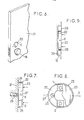
- buttons in question can even be provided "upside down” without any risk of error, as is the case when these buttons are provided on the rear face of a lock handle 18 in knob (FIG. 4) or on the underside of a lever handle 19 in a crowbar (FIG. 5).
- buttons are close enough, they can be actuated by two fingers of the same hand without it being necessary to move this hand during each complete unlocking maneuver: this circumstance further reduces the possibility identification of such a maneuver by his eyewitnesses.
- the two buttons are controlled from the same rocker permanently resiliently biased towards a central rest position.
- the bearing surface of this rocker can affect any desirable shape, for example that of a dihedral widely open towards the outside and of an edge parallel to the tilting axis: in such a case the supports exerted respectively on the two dihedral sections are used to activate the two buttons respectively.
- the rocker in question designated by the reference 22, is in the form of a cover having a flat bottom 23 and a peripheral edge 24 of relatively low constant height perpendicular to said bottom , the tilting axis X of this cover being parallel to the bottom 23 and passing through the edge 24.
- Special elastic means may be p re- seen to constantly remind the lid to its middle position.
- the cover 22 is mounted in such a way that its bottom 23 remains constantly in contact with each of the two buttons 1 and 2 or is arranged only at a very small distance from these buttons in its rest position: this is the first of these two hypotheses which was adopted in Figure 7.
- the outer face of the bottom 23, forming a support area for the user's fingers, is preferably flat, hard, smooth and relatively large, its surface generally being between 10 and 30 cm 2 .
- the cover may for this purpose be formed from an externally stamped metal plate smoothed by any desirable means such as brushing or an appropriate coating of chromium or other metal.
- the general shape of the bottom 23 may be that of a square, or of a rectangle (with the long side of this rectangle parallel or perpendicular to the axis X), or of an isosceles or equilateral triangle (with the axis of symmetry of this triangle parallel or perpendicular to the axis X), or of a trapezoid, etc.
- it is a circle whose radius is between 4 and 6 cm, the peripheral edge 24 then having a height between 5 and 7 mm.
- buttons 1 and 2 The actuation of the two buttons 1 and 2 is ensured by exerting an alternating series of presses in accordance with the code on the two halves of the bottom 23 respectively located on either side of the X axis.
- This X axis can be oriented horizontally or vertically.
- the different supports can all be executed successively using the same user finger, generally a thumb or index finger.
- the various supports can be easily executed using the index and middle fingers of the same hand of the user, oriented upwards.
- the control thus provided is particularly easy, even pleasant: in fact, because the support range is relatively large and smooth, the position of each support is not imposed with precision and we may consider that the control finger slides on said range, without loss of contact, from a position corresponding to the actuation of a button to a position corresponding to the actuation of the other button.
- the support surface is relatively large and flat, it can be used to receive any symbol or drawing.
- the cover 22 appears through a complementary light 28 hollowed out in a plate 29 suitable for closing itself a cavity 30 hollowed out in a masonry 31: the bottom 23 of this cover is then flush with the flat outer surface of said plate 29, in its rest state.
- the locking device according to the invention simultaneously eliminates all of the drawbacks indicated above for the known solutions of locking devices with key control.
- this code is composed of a relatively small number n of numbers or letters, this number being for example equal to 3, 4 or 5.
- the number of possible coded combinations is very high: this is how if the number of consecutive actuations of each button is between 1 and 16: the number of possible coded combinations is 65536 for an equal number n only 4.
Landscapes
- Physics & Mathematics (AREA)
- General Physics & Mathematics (AREA)
- Lock And Its Accessories (AREA)
- Credit Cards Or The Like (AREA)
- Supporting Of Heads In Record-Carrier Devices (AREA)
Abstract
Description
L'invention est relative aux dispositifs de verrouillage électronique et plus particulièrement à ceux, de ces dispositifs, pour lesquels la commande du déverrouillage exige l'élaboration d'une séquence d'impulsions électriques dont la composition correspond à un code prédéterminé "de référence" mis préalablement en mémoire dans le dispositif, chacune de ces impulsions étant engendrée par appui d'un doigt d'un usager connaissant le code sur une touche appropriée.The invention relates to electronic locking devices and more particularly to those of these devices, for which the unlocking command requires the development of a sequence of electrical pulses whose composition corresponds to a predetermined "reference" code. previously stored in the device, each of these pulses being generated by pressing a finger of a user knowing the code on an appropriate key.
Dans les modes de réalisation les plus répandus des dispositifs de verrouillage de ce genre, les touches à actionner pour engendrer la séquence d'impulsions codée font partie d'un clavier de commande comprenant non seulement ces touches, mais également d'autres semblables, et toutes les touches de ce clavier sont identifiées individuellement.In the most widespread embodiments of such locking devices, the keys to be actuated to generate the coded pulse sequence form part of a control keyboard comprising not only these keys, but also other similar ones, and all the keys on this keyboard are identified individually.
Ces dispositifs présentent un certain nombre d'inconvénients, en particulier en ce qui concerne la difficulté de repérer dans la pénombre les touches à actionner du clavier, la possibilité de reconstitution du code de référence par examen des touches les plus usées, l'encombrement, la complexité et le coût relativement élevé qui en résulte.These devices have a certain number of drawbacks, in particular with regard to the difficulty of locating in the dark the keys to be actuated on the keyboard, the possibility of reconstituting the reference code by examining the most used keys, the size, the resulting complexity and relatively high cost.
Une formule pour écarter ces différents inconvénients consisterait à réduire le clavier à une touche unique. Mais cette formule ne peut guère être retenue en raison du trop petit nombre de combinaisons codées qu'elle rend possibles,ce nombre étant pratiquement limité à celui des appuis successifs d'un doigt de l'usager sur la touche considérée.One formula for overcoming these various drawbacks would be to reduce the keyboard to a single key. However, this formula can hardly be retained because of the too small number of coded combinations that it makes possible, this number being practically limited to that of successive presses of a user's finger on the key considered.
En effet, il n'est guère envisageable en pratique, avec une telle touche unique, d'exploiter une suite-de trains d'impulsions successifs élaborés par les appuis successifs d'un doigt de l'usager sur cette touche vu la quasi-impossibilité que l'on rencontre dans la pratique à faire respecter par l'usager, d'une part, des seuils maxima de durée pour les intervalles entre les appuis successifs correspondant aux différentes impulsions-d'un même train et, d'autre part, des seuils minima de durée, supérieurs aux seuils maxima ci-dessus, pour les intervalles entre les trains successifs, alors que le respect de ces deux seuils est absolument nécessaire pour que l'électronique puisse différencier les différents trains.Indeed, it is hardly possible in practice, with such a unique key, to exploit a series of successive pulse trains developed by successive presses of a finger of the user on this key in view of the quasi-impossibility encountered in practice in enforcing by the user, on the one hand, maximum duration thresholds for the intervals between successive presses corresponding to the different pulses of the same train and, on the other hand, minimum duration thresholds, greater than the maximum thresholds ci above, for the intervals between successive trains, while compliance with these two thresholds is absolutely necessary so that the electronics can differentiate the different trains.
Pour écarter les inconvénients ci-dessus, il a été proposé de faire appel à deux boutons-poussoirs affectés respectivement à l'élaboration de 0 et de 1 binaires et actionnés à tour de rôle en fonction de l'écriture binaire d'un nombre de codage correspondant au code de référence.To overcome the above drawbacks, it has been proposed to use two push buttons assigned respectively to the development of 0 and 1 binary and actuated in turn according to the binary writing of a number of coding corresponding to the reference code.
Cette formule présente encore un certain nombre d'inconvénients, en particulier en ce qu'elle exige de l'usager, d'une part, le repérage, avec identification exacte, des deux boutons affectés respectivement à l'élaboration des 0 et à celle des 1 et, d'autre part, la connaissance d'un nombre binaire de codage particulièrement difficile à retenir du fait du grand nombre de ses chiffres, et en ce qu'elle offre une sécurité réduite vu le nombre relativement petit des-combinaisons correspondant à un nombre raisonnable de ces chiffres, ce nombre de combinaisons étant seulement de 128 pour un nombre binaire de codage à sept chiffres.This formula also has a certain number of drawbacks, in particular in that it requires the user, on the one hand, to locate, with exact identification, the two buttons assigned respectively to the development of the 0s and to that of the 1s and, on the other hand, the knowledge of a binary coding number which is particularly difficult to remember because of the large number of its digits, and in that it offers reduced security in view of the relatively small number of corresponding combinations to a reasonable number of these digits, this number of combinations being only 128 for a binary number of seven-digit coding.
L'invention a pour but, surtout, de remédier à ces différents inconvénients.The object of the invention is, above all, to remedy these various drawbacks.
cet effet, les dispositifs de verrouillage électronique selon l'invention, qui sont du type de ceux comportant deux boutons-poussoirs, des moyens associés à ces deux boutons pour transformer leurs actionnements respectifs en impulsions électriques émises respectivement sur deux voies parallèles, et un ensemble électronique de décodage pour recevoir et exploiter ces impulsions électriques aux fins d'émission d'un signal de déverrouillage lorsque la composition de la séquence de ces impulsions correspond au code de référence, sont caractérisés en ce que leur ensemble électronique est agencé de façon à identifier à tour de rôle les différents trains d'impulsions engendrés successivement sur les deux voi,es par chaque séquence d'actionnements réels des deux boutons, à compter les nombres d'impulsions comprises par chacun des différents trains ainsi identifiés et à comparer aux fins de décodage la composition complète de chaque séquence réelle d'impulsions ainsi analysée avec la composition complète de séquence, correspondant au code de référence, préalablement mise en mémoire, et à émettre le signal de déverrouillage chaque fois que la comparaison révèle une identité entre la séquence réelle et la séquence de code, ledit ensemble électronique comprenant des moyens de remise à zéro et étant agencé de façon telle qu'après chaque remise à zéro, la séquence d'actionnements réels des deux boutons destinée à déverrouiller le dispositif puisse être exécutée en commençant indifféremment par l'appui de l'un ou l'autre des deux boutons.To this end, the electronic locking devices according to the invention, which are of the type of those comprising two push-buttons, means associated with these two buttons to transform their respective actuations into electrical pulses transmitted respectively on two parallel channels, and an electronic decoding assembly to receive and exploit these electrical pulses for the purpose of transmitting an unlocking signal when the composition of the sequence of these pulses corresponds to the reference code, are characterized in that their electronic assembly is arranged so as to identify in turn the different trains of pulses generated successively on the two paths, by each sequence of actual actuations of the two buttons, to count the numbers of pulses included by each of the different trains thus identified and to compare for the purpose of decoding the complete composition of each actual sequence of pulses thus analyzed with the complete composition of sequence, corresponding to the reference code, beforehand memory, and to emit the unlock signal each time the comparison reveals an identity between the actual sequence and the code sequence, said electronic assembly comprising reset means and being arranged in such a way that after each reset, the actual actuation sequence of the two buttons intended for unlocking the device can be carried out starting either by pressing one or the other of the two buttons.
Par "bouton-poussoir" ou plus simplement "bouton", on entend ici et dans la suite aussi bien un bouton-poussoir proprement dit, comprenant une portée propre à être déplacée sous la pression d'un doigt à l'encontre d'un effort élastique de rappel, que plus généralement tout organe de commande présentant une plage de réception pour un doigt et agencé de façon à exploiter à des fins de commande la mise en contact d'un doigt avec une telle plage.By "push button" or more simply "button" is meant here and in the following as well a push button proper, comprising a scope suitable for being moved under the pressure of a finger against a elastic return force, which more generally any control member having a receiving range for a finger and arranged so as to exploit for control purposes the contact of a finger with such a range.
En ce point de la description, il convient de rappeler que l'on a proposé, dans le brevet France n° 80 01673 déposé le 25 janvier 1980, de réaliser une serrure commandée électroniquement dans laquelle le décodage exploite une séquence de trains d'impulsions électriques élaborés à tour de rôle selon un code prédéterminé sur deux voies distinctes.At this point in the description, it should be recalled that it has been proposed, in French patent n ° 80 01673 filed on January 25, 1980, to produce an electronically controlled lock in which the decoding exploits a sequence of pulse trains electrics developed in turn according to a predetermined code on two separate tracks.
Mais dans cette serrure, les trains sont engendrés par les sollicitations au moins angulaires d'une clé rotative dans respectivement ses deux sens possibles de rotation : ce type de commande à clé présente certes de l'intérêt dans certains cas, mais.relève d'un principe fondamentalement différent de celui de la commande à touches mis en oeuvre selon la présente invention.But in this lock, the trains are generated by the at least angular stresses of a rotary key in respectively its two possible directions of rotation: this type of key control is certainly of interest in some cases, but. a principle fundamentally different from that of the key control implemented according to the present invention.
Dans des modes de réalisation préférés. de celle-ci, on a recours en outre à l'une et/ou à l'autre des dispositions suivantes :
- - les deux boutons sont montés en un emplacement peu visible ou invisible des usagers du dispositif de verrouillage,
- - les deux boutons sont montés sur la poignée de commande d'un pêne de serrure,
- - les deux boutons sont actionnables par un basculeur unique constamment sollicité vers une position médiane de repos par des. moyens élastiques,
- - le basculeur selon l'alinéa précédent est constitué par un couvercle présentant un fond plat et un bord périphérique de hauteur constante relativement faible, couvercle monté basculant autour d'un axe parallèle à son fond et traversant son bord,
- - le fond du couvercle selon l'alinéa précédent est en permanence en contact avec chacun des deux boutons, lesquels sont situés de part et d'autre de l'axe de basculement,
- - la face extérieure du fond du couvercle selon l'un des deux alinéas précédents, face formant plage d'appui pour les doigts de l'usager, est plane, dure, lisse et relativement grande, sa surface étant comprise entre 10 et 30 cm 2,
- - la face extérieure du fond du couvercle selon l'alinéa précédent se présente sous la forme d'un cercle dont le rayon est compris entre 4 et 6 cm, le bord du couvercle ayant une hauteur comprise entre 5 et 7 mm,
- - la face extérieure du fond du couvercle affleure à la surface extérieure d'une platine au niveau du bord d'une lumière évidée dans cette platine et occupée par . ce couvercle.
- - the two buttons are mounted in a location that is hardly visible or invisible to users of the locking device,
- - the two buttons are mounted on the control handle of a lock bolt,
- - the two buttons can be actuated by a single rocker constantly urged towards a middle position of rest by. elastic means,
- the rocker according to the preceding paragraph is constituted by a cover having a flat bottom and a peripheral edge of relatively low constant height, cover mounted rocking about an axis parallel to its bottom and crossing its edge,
- - the bottom of the cover according to the previous paragraph is permanently in contact with each of the two buttons, which are located on either side of the tilt axis,
- - the outside face of the bottom of the cover according to one of the two preceding paragraphs, face forming a support area for the user's fingers, is flat, hard, smooth and relatively large, its surface being between 10 and 30 cm 2 ,
- the outside face of the bottom of the cover according to the preceding paragraph is in the form of a circle whose radius is between 4 and 6 cm, the edge of the cover having a height between 5 and 7 mm,
- - The outer face of the bottom of the cover is flush with the outer surface of a plate at the edge of a light hollowed out in this plate and occupied by. this cover.
L'invention comprend, mises à part ces dispositions principales, certaines autres dispositions qui s'utilisent de préférence en même temps et dont il sera plus explicitement question ci-après.The invention includes, apart from these main provisions, certain other provisions which are preferably used at the same time and which will be more explicitly discussed below.
Dans ce qui suit, l'on va décire des modes de réalisation préférés de l'invention en se référant aux dessins ci-annexés d'une manière bien entendu non limitative.
- La figure 1, de ces dessins, montre une porte équipée d'un dispositif de verrouillage à code établi selon l'invention.
- Les figures 2 et 3 montrent schématiquement respectivement deux ensembles électroniques susceptibles d'être compris par un tel dispositif.
- Les figures 4 et 5 montrent respectivement en vue perspective deux poignées d'une porte équipées de paires de boutons-poussoirs faisant partie d'un dispositif de verrouillage selon l'invention.
- La figure 6 montre en vue perspective partielle une porte équipée d'une paire de boutons-poussoirs du genre ci-dessus associés selon l'invention à un basculeur de commande commun.
- Les figures 7 et 8 montrent ce basculeur commun respectivement en vue latérale, parties arrachées, et en vue de face, parties arrachées.
- Figure 1 of these drawings shows a door equipped with a code locking device established according to the invention.
- Figures 2 and 3 show schematically respectively two electronic assemblies capable of being understood by such a device.
- Figures 4 and 5 show respectively in perspective view two handles of a door equipped with pairs of push buttons forming part of a locking device according to the invention.
- Figure 6 shows in partial perspective view a door equipped with a pair of pushbuttons of the above kind associated according to the invention with a common control rocker.
- Figures 7 and 8 show this common rocker respectively in side view, parts broken away, and in front view, parts broken away.
La figure 9 montre schématiquement un autre mode de montage conforme à l'invention d'un tel basculeur.FIG. 9 schematically shows another method of mounting in accordance with the invention of such a rocker.
Dans chaque cas, le dispositif de verrouillage est destiné à émettre un signal-S propre à assurer un déverrouillage effectif, en réponse à l'application sur lui d'une séquence de trains d'impulsions électriques dont la composition correspond exactement à celle d'une sé- qùence de référence ou "de code" préalablement mise en mémoire dans ce dispositif..In each case, the locking device is intended to emit an S-signal capable of ensuring effective unlocking, in response to the application to it of a sequence of trains of electrical pulses whose composition corresponds exactly to that of a reference or "code" sequence previously stored in this device.
A cet effet l'on fait comprendre à ce dispositif de verrouillage:
- - deux boutons-
poussoirs 1 et 2 (figures 1 à 5) ou touches analogues au sens défini ci-dessus, dont certains modes de montage et de commande seront précisés plus loin, - - des organes 3 et 4 (figures 2 et 3) pour transformer les actionnements de ces boutons en impulsions électriques émises respectivement sur deux voies distinctes 5 et 6,
- .- et un ensemble électronique 7 propre à exploiter aux fins de décodage par comparaison avec la (ou les) référence(s) mise en mémoire, chaque séquence des trains d'impulsions émis successivement sur les deux voies 5 et 6 en réponse aux actionnements en question desdits boutons.
- - two
pushbuttons 1 and 2 (Figures 1 to 5) or similar keys in the sense defined above, some of the mounting and control modes of which will be specified below, - organs 3 and 4 (FIGS. 2 and 3) for transforming the actuations of these buttons into electrical pulses emitted respectively on two separate channels 5 and 6,
- .- and an electronic assembly 7 suitable for operating for the purpose of decoding by comparison with the reference (s) stored in memory, each sequence of pulse trains transmitted successively on the two channels 5 and 6 in response to the actuations said buttons.
Les organes 3 et 4 destinés à engendrer des impulsions électriques sur les deux voies 5 et 6 en réponse aux actionnements des boutons 1 et 2 peuvent être agencés de toute manière désirable : ils sont notamment constitués par des interrupteurs électriques montés dans des circuits d'alimentation électrique, ou bien par des transducteurs propres à exploiter aux fins de création d'impulsions électriques les variations d'une pression de contact (transducteurs électromécaniques), ou celles d'une capacité, équipée ou non d'un électret (transducteurs électrostatiques), ou encore celles d'un circuit magnétique propre notamment à engendrer une tension par effet Hall (transducteurs électromagnétiques), etc.The members 3 and 4 intended to generate electrical pulses on the two channels 5 and 6 in response to the actuations of the
Deux modes de réalisation de l'ensemble électronique 7 ont été schématisés respectivement sur les figures 2 et 3.Two embodiments of the electronic assembly 7 have been shown diagrammatically in FIGS. 2 and 3 respectively.
Le premier de ces deux ensembles 7,schématisé sur la figure 2, comporte :
- - une
bascule 8 de "changement de voie" à laquelle sont connectées les deux voies 5 et 6, bascule agencée de façon à basculer chaque fois qu'elle reçoit une impulsion provenant d'une voie nouvelle et à émettre une impulsion chaque fois qu'elle bascule, - - une porte ET 9 alimentée, comme la
bascule 8, par les deux voies 5 et 6, - - un compteur d'impulsions 10 recevant la sortie de la porte 9 et remis à zéro par la sortie de la
bascule 8 lors de chaque "changement de voie", - - un compteur d'adresse 11 recevant aussi la sortie de la
bascule 8 et agencé de façon telle que son contenu passe à 1 lors de la réception de la première impulsion de chaque séquence à décoder et augmente de 1 à chaque changement de voie, - - une
mémoire 12 dans laquelle a été enregistré le code de référence, code composé d'une suite de nombres "adressés", cette mémoire recevant la sortie du compteur d'adresse 11, - -
un comparateur 13 recevant à la fois la sortie du compteur d'impulsions 10 et celle de la mémoire 12 à chaque modification du contenu du compteur d'adresse 11, - -
un organe 14 générateur de signal d'erreur dont les entrées sont reliées au compteur d'adresse 11 et au comparateur 13 et propre à remettre à zéro le compteur d'impulsions 10 et ledit compteur d'adresse 11 dès qu'une manoeuvre se révèle incorrecte (après un retard t relativement faible), du fait notamment d'un défaut d'identité entre le nombre des impulsions d'un train appliqué sur le comparateur 13 et le nombre de référence correspondant alors délivré par la mémoire 12, ou encore d'un dépassement du nombre des adresses, ou suite à un dépassement du temps maximum t1 autorisé pour l'opération de décodage (par exemple 20 secondes), - -
et un actionneur 15 recevant les sorties du compteur d'adresse 11 et du comparateur 13 et propre à élaborer en conséquence le signal de déblocage S à la fin du décodage si celui-ci s'est révélé correct, éventuellement après un léger retard, par exemple de l'ordre de 0,5 à 1 seconde.
- - a flip-
flop 8 for "changing lanes" to which the two channels 5 and 6 are connected, flip-flop arranged so as to switch each time it receives an impulse from a new channel and to send a pulse each time that it rocks, - - an AND gate 9 supplied, like flip-
flop 8, by the two channels 5 and 6, - - a
pulse counter 10 receiving the output of gate 9 and reset to zero by the output of flip-flop 8 during each "lane change", - an address counter 11 also receiving the output of the flip-
flop 8 and arranged in such a way that its content goes to 1 when the first pulse of each sequence to be decoded is received and increases by 1 at each channel change, - a
memory 12 in which the reference code has been recorded, a code composed of a series of "addressed" numbers, this memory receiving the output of the address counter 11, - - a
comparator 13 receiving both the output of thepulse counter 10 and that ofmemory 12 each time the content of address counter 11 is modified, - an
organ 14 generating an error signal, the inputs of which are connected to the address counter 11 and to thecomparator 13 and capable of resetting thepulse counter 10 and said address counter 11 as soon as an operation is reveals incorrect (after a relatively small delay t), due in particular to a lack of identity between the number of pulses of a train applied to thecomparator 13 and the corresponding reference number then delivered by thememory 12, or else an overshooting of the number of addresses, or following an overshooting of the maximum time t 1 authorized for the decoding operation (for example 20 seconds), - - and an
actuator 15 receiving the outputs of the address counter 11 and of thecomparator 13 and suitable for developing accordingly the unlocking signal S at the end of the decoding if the latter has proved to be correct, possibly after a slight delay, for example of the order of 0.5 to 1 second.
La "logique câblée" constituée des circuits 8 à 15 ci-dessus, discrets ou intégrés, pourrait être remplacée par une logique programmée à microprocesseurs ou à microcalculateurs : cette dernière construction présente l'avantage d'un très faible volume ; elle présente aussi l'avantage d'ure très faible consommation, en particulier lorsqu'elle est associée à des moyens assurant sa mise automatique à l'état de "veille" ou plutôt de "sommeil" après un certain délai postérieur à la première impulsion de décodage : on sait que, pour un tel état, la consommation électrique est pratiquement nulle, étant limitée à celle juste suffisante pour conserver les mémoires ; un circuit spécial est alors bien entendu prévu pour "réveiller" l'ensemble dès le début de chaque décodage.The "wired logic" consisting of
C'est le cas du second exemple d'ensemble électronique 7 qui a été schématisé sur la figure 3.This is the case of the second example of an electronic assembly 7 which has been shown diagrammatically in FIG. 3.
Cet ensemble comprend, en plus de la mémoire 12, un microcalculateur 16 et un circuit de réveil 17. Ce dernier circuit, seul constamment en fonction ou "en veille", est d'un type à très faible consommation élec- 'trique, par exemple un circuit intégré C.MOS. Son rôle est de mettre en route ou de "réveiller" le microcalculateur 16 dès qu'une impulsion électrique parvient sur lui depuis l'une des deux voies 5 et 6. Ce microcalculateur enregistre alors dans une mémoire interne la composition de la séquence d'impulsions qu'il reçoit, la compare à la composition de référence ou de code contenue dans la mémoire 12 et émet un signal S s'il y a identité entre les deux compositions ainsi comparées. Dans le cas contraire, le microcalculateur devient indifférent aux impulsions qu'il reçoit pendant une durée prédéterminée qui peut être de l'ordre de 10 secondes.This assembly comprises, in addition to the
Après chaque décodage correct, ou après chaque anomalie, le microcalculateur est remis automatiquement en son état de sommeil pour lequel sa consommation électrique est quasiment nulle.After each correct decoding, or after each anomaly, the microcomputer is automatically returned to its sleep state for which its electrical consumption is almost zero.
Ce microcalculateur pourrait être remplacé par un microprocesseur associé à des circuits périphériques tels qu'une mémoire de programme et que des dispositifs d'entrée-sortie.This microcomputer could be replaced by a microprocessor associated with peripheral circuits such as a program memory and that input-output devices.
L'ensemble électronique 7 peut comprendre également une pile (non représentée) pour son alimentation électrique (alimentation réduite au repos à celle du circuit de réveil, lorsqu'il en est prévu un) : cette pile peut servir à alimenter aussi un circuit propre à exploiter le signal de déverrouillage S, si ce dernier circuit est prévu à faible consommation.The electronic assembly 7 can also include a battery (not shown) for its electrical supply (supply reduced at rest to that of the wake-up circuit, when one is provided): this battery can be used to supply also a circuit suitable for exploiting the unlocking signal S, if the latter circuit is provided with low consumption.
Le fonctionnement du dispositif de verrouillage tel que décrit ci-dessus est le suivant.The operation of the locking device as described above is as follows.
Il exige uniquement la connaissance du code, lequel se présente sous la forme d'un nombre de n chiffres ou d'un ensemble-équivalent.It only requires knowledge of the code, which is in the form of a number of n digits or an equivalent set.
C'est ainsi que le code 7519 correspondant à un nombre n égal à 4 peut être assimilé aux quatre lettres du mot GEAI, plus facile à retenir, lettres dont les rangs respectifs dans l'alphabet sont 7,- 5, 1 et 9.Thus the code 7519 corresponding to a number n equal to 4 can be assimilated to the four letters of the word GEAI, easier to remember, letters whose respective ranks in the alphabet are 7, - 5, 1 and 9.
Connaissant ce code, il suffit à l'usager d'appuyer d'abord sur l'un des deux boutons 1 et 2 un nom- - bre de fois égal au premier chiffre du code, puis sur l'autre bouton un nombre de fois éga-1 au second chiffre du code, puis à nouveau sur le premier bouton un nombre de fois égal au troisième chiffre du code et ainsi de suite jusqu'à exécution de la succession d'appuis du rang n : le signal S de déblocage est alors émis par l'actionneur 15.Knowing this code, it suffices for the user to first press one of the two
Ce signal S peut être exploité à toutes fins désirables telles que l'ouverture d'une porte - porte pouvant livrer accès par exemple à un immeuble, à un- appartement ou à un coffre-fort - le déblocage d'un volant de véhicule automobile, l'alimentation électrique d'un appareil ...This signal S can be used for any desirable purpose such as opening a door - door that can provide access for example to a building, an apartment or a safe - unlocking a steering wheel of a motor vehicle , the power supply of a device ...
Il est à noter que, pour assurer le déverrouillage ci-dessus, l'usager détenteur du code peut commencer à appuyer sur n'importe lequel des deux boutons 1 et 2.Note that, to ensure the above unlocking, the user holding the code can start pressing any of the two
C'est là un avantage capital de la présente invention car il en résulte qu'il est inutile aux usagers d'identifier exactement les deux boutons en question et que ceux-ci peuvent donc être disposés en des ern- placements où ils sont repérables seulement au toucher, étant alors hors de la vue des usagers.This is a capital advantage of the present invention since it results that it is useless for users to identify exactly the two buttons in question. and that these can therefore be arranged in locations where they can be identified only by touch, being then out of the sight of the users.
Une telle disposition des boutons cachée aux regards présente également l'avantage important de dissimuler au moins en partie les manoeuvres de ces boutons, ce qui rend plus difficile, voire impossible, même en plein jour, l'identification du code par les tiers témoins desdites manoeuvres.Such an arrangement of the buttons hidden from view also has the significant advantage of at least partially concealing the operations of these buttons, which makes it more difficult, if not impossible, even in broad daylight, for the identification of the code by the third witnesses of said said maneuvers.
Il résulte également du fait qu'il est inutile de voir les boutons pour les actionner que leurs actionnements peuvent intervenir dans l'obscurité et peuvent même être effectués par des usagers mal voyants.It also results from the fact that it is useless to see the buttons for actuating them that their actuations can intervene in the dark and can even be carried out by visually impaired users.
Les-actionnements en question peuvent même être assurés "à l'envers" sans aucun risqué d'erreur, comme c'est le cas lorsque ces boutons sont prévus sur la face arrière d'une poignée de serrure 18 en pommeau (figure 4) ou sur la face inférieure d'une poignée de serrure 19 en bec-de-cane (figure 5).The actuations in question can even be provided "upside down" without any risk of error, as is the case when these buttons are provided on the rear face of a
Cette possibilité de monter les boutons "à l'envers" sans risque d'erreur permet également de résoudre automatiquement le problème posé par la commande de sécurité d'une même serrure de porte à partir des deux côtés de cette porte, commandes qui sont souvent inversées et exigent alors des suites inverses de manoeuvres pour les deux côtés de la porte.This possibility of mounting the buttons "upside down" without risk of error also automatically solves the problem posed by the security control of the same door lock from both sides of this door, commands which are often reversed and therefore require reverse sequences of operations for both sides of the door.
On notera par ailleurs que le remplacement des claviers de commande connus par seulement deux boutons conduit à une réduction considérable de l'encombrement du dispositif de verrouillage, réduction permettant en particulier un montage direct de ce dispositif sur le boîtier 20 d'une serrure de porte 21 (figure 1), et même un tel montage direct sur une poignée, comme il a été indiqué ci-dessus en référence aux figures 4 et 5. On peut ajouter que, si les deux boutons sont suffisamment rapprochés, ils peuvent être actionnés par deux doigts d'une même main sans qu'il soit nécessaire de déplacer cette main au cours de chaque manoeuvre complète de déverrouillage : cette circonstance réduit encore la possibilité d'identification d'une telle manoeuvre par ses témoins occulaires.It will also be noted that the replacement of the known control keypads by only two buttons leads to a considerable reduction in the size of the locking device, a reduction allowing in particular a direct mounting of this device on the
Dans des modes de réalisation particulièrement avantageux, les deux boutons sont commandés à partir d'un même basculeur sollicité élastiquement en permanence vers une position de repos médiane.In particularly advantageous embodiments, the two buttons are controlled from the same rocker permanently resiliently biased towards a central rest position.
La plage d'appui de ce basculeur peut affecter toute forme désirable, par exemple celle d'un dièdre largement ouvert vers l'extérieur et d'arête parallèle à l'axe de basculement : dans un tel cas les appuis exercés respectivement sur les deux pans du dièdre servent respectivement à actionner les deux boutons.The bearing surface of this rocker can affect any desirable shape, for example that of a dihedral widely open towards the outside and of an edge parallel to the tilting axis: in such a case the supports exerted respectively on the two dihedral sections are used to activate the two buttons respectively.
Dans les cas illustrés sur les figures 6 à 9, le basculeur en question, désigné par la-référence 22, se présente sous la forme d'un couvercle présentant un fond plat 23 et un bord périphérique 24 de hauteur constante relativement faible perpendiculaire audit fond, l'axe X de basculement de ce couvercle étant parallèle au fond 23 et traversant le bord 24.In the cases illustrated in Figures 6 to 9, the rocker in question, designated by the
Des moyens élastiques spéciaux peuvent être pré- vus pour rappeler constamment ce couvercle vers sa position médiane de repos.Special elastic means may be p re- seen to constantly remind the lid to its middle position.
Mais il peut être avantageux d'assurer ce rappel à l'aide des moyens élastiques qui ont déjà été prévus pour rappeler chacun des deux boutons vers sa position - sortie de repos.However, it may be advantageous to provide this reminder using the elastic means which have already been provided for returning each of the two buttons to its position - out of rest.
A cet effet, le couvercle 22 est monté de façon telle que son fond 23 demeure constamment en contact avec chacun des deux boutons 1 et 2 ou soit disposé seulement à une très petite distance de ces boutons en sa position de repos : c'est la première de ces deux hypothèses qui a été adoptée sur la figure 7.For this purpose, the
La face extérieure du fond 23, formant plage d'appui pour les doigts de l'usager, est de préférence plane, dure, lisse et relativement grande, sa surface étant généralement comprise entre 10 et 30 cm2.The outer face of the bottom 23, forming a support area for the user's fingers, is preferably flat, hard, smooth and relatively large, its surface generally being between 10 and 30 cm 2 .
Le couvercle peut à cet effet être constitué à partir d'une plaquette métallique emboutie extérieurement lissée par tous moyens désirables tels qu'un brossage ou qu'un revêtement approprié de chrome ou autre métal.The cover may for this purpose be formed from an externally stamped metal plate smoothed by any desirable means such as brushing or an appropriate coating of chromium or other metal.
La forme générale du fond 23 peut être celle d'un carré, ou d'un rectangle (avec le grand côté de ce rectangle parallèle ou perpendiculaire à l'axe X), ou d'un triangle isocèle ou équilatéral (avec l'axe de symétrie de ce triangle parallèle ou perpendiculaire à l'axe X), ou d'un trapèze, etc.The general shape of the bottom 23 may be that of a square, or of a rectangle (with the long side of this rectangle parallel or perpendicular to the axis X), or of an isosceles or equilateral triangle (with the axis of symmetry of this triangle parallel or perpendicular to the axis X), or of a trapezoid, etc.
Dans le mode de réalisation préféré illustré, il s'agit d'un cercle dont la rayon est compris entre 4 et 6 cm, le bord périphérique 24 ayant alors une hauteur comprise entre 5 et 7 mm.In the preferred embodiment illustrated, it is a circle whose radius is between 4 and 6 cm, the
L'actionnement des deux boutons 1 et 2 est assuré en exerçant une suite alternée d'appuis conforme au code sur respectivement les deux moitiés du fond 23 situées de part et d'autre de l'axe X.The actuation of the two
Cet axe X peut être orienté horizontalement ou verticalement.This X axis can be oriented horizontally or vertically.
S'il est horizontal, les différents appuis peuvent tous être exécutés successivement à l'aide d'un même doigt de l'usager, généralement un pouce ou un index.If it is horizontal, the different supports can all be executed successively using the same user finger, generally a thumb or index finger.
Si l'axe X est vertical, les différents appuis peuvent être facilement exécutés à l'aide de l'index et du majeur d'une même main de l'usager, orients vers le haut.If the X axis is vertical, the various supports can be easily executed using the index and middle fingers of the same hand of the user, oriented upwards.
Dans tous les cas, la commande ainsi assurée est particulièrement facile, voire agréable: en effet, du fait que la plage d'appui-est relativement grande et lisse, la position de chaque appui n'est pas imposée avec précision et l'on peut envisager que le doigt de commande glisse sur ladite plage, sans perte de contact, d'une position correspondant à l'actionnement d'un bouton à une position correspondant à l'actionnement de l'autre bouton.In all cases, the control thus provided is particularly easy, even pleasant: in fact, because the support range is relatively large and smooth, the position of each support is not imposed with precision and we may consider that the control finger slides on said range, without loss of contact, from a position corresponding to the actuation of a button to a position corresponding to the actuation of the other button.
Bien entendu, du fait que la plage d'appui est relativement grande et plane, on peut l'utiliser pour recevoir un symbole ou dessin quelconque.Of course, because the support surface is relatively large and flat, it can be used to receive any symbol or drawing.
On peut également prévoir de matérialiser sur ce fond la zone neutre correspondant à l'axe par une nervure ou rigole en vue de faciliter dans certains cas la reconnaissance tactile de cette zone.One can also provide for materializing on this background the neutral zone corresponding to the axis by a rib or channel in order to facilitate in certain cases the tactile recognition of this zone.
Sur les figures 7 et 8 on voit encore un anneau 25 fixé par des vis.26 sur un support approprié (ici porte 21) et propre à recevoir d'une part les boutons 1 et 2 et d'autre part des tourillons 27 d'axe X, le montage basculant du couvercle 22 sur ces tourillons 27 ayant pour effet de faire coiffer quasi-jointivement ledit anneau par ledit couvercle.In Figures 7 and 8 we still see a
Dans la variante schématisée sur la figure 9, le couvercle 22 apparaît à travers une lumière complémentaire 28 évidée dans une platine 29 propre à refermer elle-même une cavité 30 évidée dans une maçonnerie 31 : le fond 23 de ce couvercle affleure alors exactement à la surface extérieure plane de ladite platine 29, en son état de repos.In the variant shown diagrammatically in FIG. 9, the
Quel que soit le mode de réalisation adopté, le dispositif de verrouillage selon l'invention supprime simultanément la totalité des inconvénients signalés ci-dessus pour les solutions connues des dispositifs de verrouillage à commande par touches.Whatever the embodiment adopted, the locking device according to the invention simultaneously eliminates all of the drawbacks indicated above for the known solutions of locking devices with key control.
En particulier, le code permettant le déverrouillage peut facilement être retenu par les usagers, vu q.ue ce code est composé d'un nombre n de chiffres ou lettres relativement petit, ce nombre étant par exemple égal à 3, 4 ou 5.In particular, the code allowing unlocking can easily be retained by users, given q. ue this code is composed of a relatively small number n of numbers or letters, this number being for example equal to 3, 4 or 5.
Malgré cette simplicité, le nombre des combinaisons codées possibles est très élevé : c'est ainsi que si le nombre d'actionnements consécutifs de chaque bouton est compris entre 1 et 16 : le nombre des combinaisons codées possibles est de 65536 pour un nombre n égal à 4 seulement.Despite this simplicity, the number of possible coded combinations is very high: this is how if the number of consecutive actuations of each button is between 1 and 16: the number of possible coded combinations is 65536 for an equal number n only 4.
On peut ajouter qu'avec la solution selon l'invention, il n'est pas nécessaire de respecter des seuils maxima de durée entre les actionnements successifs d'un même bouton et des seuils minima de durée entre le dernier actionnement d'un bouton et le premier actionnement consécutif de l'autre bouton : en effet, du fait-que les impulsions électriques correspondant aux actionnements des deux boutons sont émises respectivement sur deux voies distinctes, l'électronique distingue automatiquement, dans la suite d'impulsions à analyser, celles qui correspondent à des trains successifs, et celles qui correspondent aux impulsions successives d'un même train.It may be added that with the solution according to the invention, it is not necessary to respect maximum duration thresholds between successive actuations of the same button and minimum duration thresholds between the last actuation of a button and the first consecutive actuation of the other button: in fact, due to the fact that the electrical pulses corresponding to the actuations of the two buttons are sent respectively on two separate channels, the electronics automatically distinguish, in the sequence of pulses to be analyzed, those which correspond to successive trains, and those which correspond to successive pulses of the same train.
Claims (9)
Priority Applications (1)
| Application Number | Priority Date | Filing Date | Title |
|---|---|---|---|
| AT82401010T ATE22589T1 (en) | 1981-06-04 | 1982-06-03 | ELECTRONICALLY CODEABLE LOCKING ARRANGEMENTS. |
Applications Claiming Priority (2)
| Application Number | Priority Date | Filing Date | Title |
|---|---|---|---|
| FR8111102 | 1981-06-04 | ||
| FR8111102A FR2507411A1 (en) | 1981-06-04 | 1981-06-04 | IMPROVEMENTS TO ELECTRONIC CODE LOCKING DEVICES |
Publications (2)
| Publication Number | Publication Date |
|---|---|
| EP0068936A1 true EP0068936A1 (en) | 1983-01-05 |
| EP0068936B1 EP0068936B1 (en) | 1986-10-01 |
Family
ID=9259196
Family Applications (1)
| Application Number | Title | Priority Date | Filing Date |
|---|---|---|---|
| EP82401010A Expired EP0068936B1 (en) | 1981-06-04 | 1982-06-03 | Coded electronic locking devices |
Country Status (7)
| Country | Link |
|---|---|
| US (1) | US4485381A (en) |
| EP (1) | EP0068936B1 (en) |
| JP (1) | JPS57209373A (en) |
| AT (1) | ATE22589T1 (en) |
| CA (1) | CA1225841A (en) |
| DE (1) | DE3273536D1 (en) |
| FR (1) | FR2507411A1 (en) |
Cited By (3)
| Publication number | Priority date | Publication date | Assignee | Title |
|---|---|---|---|---|
| FR2593218A1 (en) * | 1986-01-20 | 1987-07-24 | Pieddeloup Daniel | Device for slaving by codification using pulse generators of various technical origins |
| FR2669162A1 (en) * | 1990-11-12 | 1992-05-15 | Houille Alain | Device for forming a digital code and product dispenser apparatus equipped with such a device |
| WO1994017268A1 (en) * | 1993-01-28 | 1994-08-04 | Gerhard Weber | Keyless electronic closing system |
Families Citing this family (12)
| Publication number | Priority date | Publication date | Assignee | Title |
|---|---|---|---|---|
| US4754423A (en) * | 1986-06-16 | 1988-06-28 | Motorola, Inc. | Electronic selector and method for selecting desired functions and levels |
| JPH0637187Y2 (en) * | 1986-12-16 | 1994-09-28 | 自動車電機工業株式会社 | Door lock actuator drive |
| US4912460A (en) * | 1987-07-16 | 1990-03-27 | John Chu | Electrostatically activated gating mechanism |
| US5563586A (en) * | 1994-07-29 | 1996-10-08 | Ambitech Industries, Inc. | Apparatus for limiting control of electrical equipment |
| FR2821107A1 (en) * | 2001-02-22 | 2002-08-23 | Valeo Electronique | Hands free system, for controlling vehicle locking system from outside cabin, comprises electronic detection of user hand actions near door handle, comparison with stored signals, identification and operation of actuators |
| US20050225431A1 (en) * | 2002-03-05 | 2005-10-13 | Jong-O Kim | Apparatus for opening/closing the door |
| US20120306614A1 (en) * | 2010-06-07 | 2012-12-06 | Essex Electronics, Inc. | Single element keyless control system |
| JP6001208B2 (en) | 2013-03-15 | 2016-10-05 | スペクトラム ブランズ インコーポレイテッド | Wireless lock set with integrated antenna, touch activation function and optical communication device |
| US10300886B2 (en) * | 2016-03-15 | 2019-05-28 | GM Global Technology Operations LLC | Keyless control system |
| WO2017165349A1 (en) | 2016-03-22 | 2017-09-28 | Spectrum Brands, Inc. | Garage door opener with touch sensor authentication |
| US11450158B2 (en) | 2018-01-05 | 2022-09-20 | Spectrum Brands, Inc. | Touch isolated electronic lock |
| US11639617B1 (en) | 2019-04-03 | 2023-05-02 | The Chamberlain Group Llc | Access control system and method |
Citations (7)
| Publication number | Priority date | Publication date | Assignee | Title |
|---|---|---|---|---|
| US3320395A (en) * | 1966-02-01 | 1967-05-16 | Allen Bradley Co | Operating mechanism for manually actuated switches |
| FR2070316A5 (en) * | 1969-12-01 | 1971-09-10 | Legrand Sa | |
| US3660729A (en) * | 1971-01-11 | 1972-05-02 | Bell Telephone Labor Inc | Electronic combination lock system |
| FR2107636A5 (en) * | 1970-09-14 | 1972-05-05 | Siemens Ag | |
| US3663781A (en) * | 1970-11-23 | 1972-05-16 | Scm Corp | Electrical switch having a flexible one-piece actuator |
| GB1314523A (en) * | 1969-01-31 | 1973-04-26 | Smiths Industries Ltd | Access-control equipment |
| US4222088A (en) * | 1978-09-27 | 1980-09-09 | Burton Richard H | Electronic lock |
Family Cites Families (7)
| Publication number | Priority date | Publication date | Assignee | Title |
|---|---|---|---|---|
| US1449248A (en) * | 1921-09-14 | 1923-03-20 | George D Rathbun | Combination locking mechanism |
| US3825898A (en) * | 1971-02-17 | 1974-07-23 | Phillips Screw Co | Safety lock with provision for key user identification |
| US3764982A (en) * | 1972-08-30 | 1973-10-09 | R Kidnocker | Sequentially coded actuating device |
| US4148092A (en) * | 1977-08-04 | 1979-04-03 | Ricky Martin | Electronic combination door lock with dead bolt sensing means |
| FR2420008A1 (en) * | 1978-03-17 | 1979-10-12 | Neiman Sa | MOTOR VEHICLE LOCK CONTROL DEVICE |
| JPS5548737A (en) * | 1978-10-02 | 1980-04-08 | Konishiroku Photo Ind Co Ltd | Photoelectrically focus detecting device mounted camera |
| FR2474574A1 (en) * | 1980-01-25 | 1981-07-31 | Jacques Lewiner | IMPROVEMENTS ON COMBINATION SECURITY LOCKS |
-
1981
- 1981-06-04 FR FR8111102A patent/FR2507411A1/en active Granted
-
1982
- 1982-05-26 CA CA000403742A patent/CA1225841A/en not_active Expired
- 1982-06-03 EP EP82401010A patent/EP0068936B1/en not_active Expired
- 1982-06-03 DE DE8282401010T patent/DE3273536D1/en not_active Expired
- 1982-06-03 AT AT82401010T patent/ATE22589T1/en not_active IP Right Cessation
- 1982-06-04 US US06/385,103 patent/US4485381A/en not_active Expired - Fee Related
- 1982-06-04 JP JP57095020A patent/JPS57209373A/en active Pending
Patent Citations (7)
| Publication number | Priority date | Publication date | Assignee | Title |
|---|---|---|---|---|
| US3320395A (en) * | 1966-02-01 | 1967-05-16 | Allen Bradley Co | Operating mechanism for manually actuated switches |
| GB1314523A (en) * | 1969-01-31 | 1973-04-26 | Smiths Industries Ltd | Access-control equipment |
| FR2070316A5 (en) * | 1969-12-01 | 1971-09-10 | Legrand Sa | |
| FR2107636A5 (en) * | 1970-09-14 | 1972-05-05 | Siemens Ag | |
| US3663781A (en) * | 1970-11-23 | 1972-05-16 | Scm Corp | Electrical switch having a flexible one-piece actuator |
| US3660729A (en) * | 1971-01-11 | 1972-05-02 | Bell Telephone Labor Inc | Electronic combination lock system |
| US4222088A (en) * | 1978-09-27 | 1980-09-09 | Burton Richard H | Electronic lock |
Cited By (3)
| Publication number | Priority date | Publication date | Assignee | Title |
|---|---|---|---|---|
| FR2593218A1 (en) * | 1986-01-20 | 1987-07-24 | Pieddeloup Daniel | Device for slaving by codification using pulse generators of various technical origins |
| FR2669162A1 (en) * | 1990-11-12 | 1992-05-15 | Houille Alain | Device for forming a digital code and product dispenser apparatus equipped with such a device |
| WO1994017268A1 (en) * | 1993-01-28 | 1994-08-04 | Gerhard Weber | Keyless electronic closing system |
Also Published As
| Publication number | Publication date |
|---|---|
| CA1225841A (en) | 1987-08-25 |
| ATE22589T1 (en) | 1986-10-15 |
| US4485381A (en) | 1984-11-27 |
| FR2507411B1 (en) | 1985-04-26 |
| FR2507411A1 (en) | 1982-12-10 |
| DE3273536D1 (en) | 1986-11-06 |
| JPS57209373A (en) | 1982-12-22 |
| EP0068936B1 (en) | 1986-10-01 |
Similar Documents
| Publication | Publication Date | Title |
|---|---|---|
| EP0068936B1 (en) | Coded electronic locking devices | |
| EP0099762B1 (en) | Coded remote control devices | |
| FR2796978A1 (en) | LOCK CYLINDER | |
| EP0196989B1 (en) | Electromechanical lock | |
| EP2650457B1 (en) | Door opening control device | |
| FR2769034A1 (en) | ELECTRICAL LOCK WITH ENCODED EXTERNAL POWER SUPPLY | |
| EP0147276B1 (en) | Coded control devices | |
| CA1258382A (en) | Safety device for the closing and opening of doors, windows, and the like | |
| FR3081236A1 (en) | COMPACT DEVICE FOR CONTROLLING ELECTRIC WINDOWS | |
| EP0204050B1 (en) | Electric or electronic control keyboards | |
| FR2607545A1 (en) | Electronic security system comprising a multi-code key and a lock whose mechanism cannot be forced | |
| FR3042897B1 (en) | CONNECTED ELECTRONIC PADLOCK, METHODS | |
| EP2920655A2 (en) | Mode of activation of an electronic watch | |
| EP4007117B1 (en) | Power management method, for a detector of the position of a mobile fitting part for a frame | |
| FR2561703A1 (en) | Access device with lock and coded key | |
| EP0200636B1 (en) | Electromechanical driving unit operated by a code and including an alarm system actuated under stress conditions | |
| EP4343089A1 (en) | Home maintenance assistance system | |
| JP3296860B2 (en) | Window crescent | |
| FR2539247A1 (en) | Keyboard with adaptable key marking | |
| EP1662845B1 (en) | Method for programming the time delay duration of a switch clock | |
| JP2544560Y2 (en) | Alarm Clock | |
| FR2493895A3 (en) | Electronic vehicle locking system controller - uses pushbuttons to individually set each of three ring counters so their outputs cause NAND gate to change state and drive solenoid | |
| FR2832017A1 (en) | Portable telephone function calling mechanism having switched signal activated function assembly with signals formed long/short action combinations keyboard formed | |
| JPS6036173Y2 (en) | cosmetic compact | |
| FR3082499A1 (en) | CYCLE PROVIDED WITH AN ANTITHEFT SYSTEM FORK LOCK AND AUTOMATIC SYSTEM FOR PROVIDING SUCH A CYCLE |
Legal Events
| Date | Code | Title | Description |
|---|---|---|---|
| PUAI | Public reference made under article 153(3) epc to a published international application that has entered the european phase |
Free format text: ORIGINAL CODE: 0009012 |
|
| AK | Designated contracting states |
Designated state(s): AT BE CH DE FR GB IT LI NL SE |
|
| 17P | Request for examination filed |
Effective date: 19830609 |
|
| GRAA | (expected) grant |
Free format text: ORIGINAL CODE: 0009210 |
|
| AK | Designated contracting states |
Kind code of ref document: B1 Designated state(s): AT BE CH DE FR GB IT LI NL SE |
|
| PG25 | Lapsed in a contracting state [announced via postgrant information from national office to epo] |
Ref country code: NL Effective date: 19861001 Ref country code: AT Effective date: 19861001 |
|
| REF | Corresponds to: |
Ref document number: 22589 Country of ref document: AT Date of ref document: 19861015 Kind code of ref document: T |
|
| ITF | It: translation for a ep patent filed |
Owner name: ING. C. GREGORJ S.P.A. |
|
| PG25 | Lapsed in a contracting state [announced via postgrant information from national office to epo] |
Ref country code: SE Effective date: 19861031 |
|
| REF | Corresponds to: |
Ref document number: 3273536 Country of ref document: DE Date of ref document: 19861106 |
|
| NLV1 | Nl: lapsed or annulled due to failure to fulfill the requirements of art. 29p and 29m of the patents act | ||
| PLBE | No opposition filed within time limit |
Free format text: ORIGINAL CODE: 0009261 |
|
| STAA | Information on the status of an ep patent application or granted ep patent |
Free format text: STATUS: NO OPPOSITION FILED WITHIN TIME LIMIT |
|
| 26N | No opposition filed | ||
| PGFP | Annual fee paid to national office [announced via postgrant information from national office to epo] |
Ref country code: GB Payment date: 19930528 Year of fee payment: 12 |
|
| PGFP | Annual fee paid to national office [announced via postgrant information from national office to epo] |
Ref country code: CH Payment date: 19930617 Year of fee payment: 12 |
|
| ITTA | It: last paid annual fee | ||
| PGFP | Annual fee paid to national office [announced via postgrant information from national office to epo] |
Ref country code: BE Payment date: 19930709 Year of fee payment: 12 |
|
| PG25 | Lapsed in a contracting state [announced via postgrant information from national office to epo] |
Ref country code: GB Effective date: 19940603 |
|
| PG25 | Lapsed in a contracting state [announced via postgrant information from national office to epo] |
Ref country code: LI Effective date: 19940630 Ref country code: CH Effective date: 19940630 Ref country code: BE Effective date: 19940630 |
|
| PGFP | Annual fee paid to national office [announced via postgrant information from national office to epo] |
Ref country code: DE Payment date: 19940630 Year of fee payment: 13 |
|
| BERE | Be: lapsed |
Owner name: BERTHIER GILBERT Effective date: 19940630 Owner name: HENNION CLAUDE Effective date: 19940630 Owner name: LEWINER JACQUES Effective date: 19940630 |
|
| GBPC | Gb: european patent ceased through non-payment of renewal fee |
Effective date: 19940603 |
|
| REG | Reference to a national code |
Ref country code: CH Ref legal event code: PL |
|
| PGFP | Annual fee paid to national office [announced via postgrant information from national office to epo] |
Ref country code: FR Payment date: 19950529 Year of fee payment: 14 |
|
| PG25 | Lapsed in a contracting state [announced via postgrant information from national office to epo] |
Ref country code: DE Effective date: 19960301 |
|
| PG25 | Lapsed in a contracting state [announced via postgrant information from national office to epo] |
Ref country code: FR Effective date: 19970228 |
|
| REG | Reference to a national code |
Ref country code: FR Ref legal event code: ST |