EP0065454A1 - Method and device for reconstructing an analogue luminance signal from a digital signal - Google Patents
Method and device for reconstructing an analogue luminance signal from a digital signal Download PDFInfo
- Publication number
- EP0065454A1 EP0065454A1 EP82400826A EP82400826A EP0065454A1 EP 0065454 A1 EP0065454 A1 EP 0065454A1 EP 82400826 A EP82400826 A EP 82400826A EP 82400826 A EP82400826 A EP 82400826A EP 0065454 A1 EP0065454 A1 EP 0065454A1
- Authority
- EP
- European Patent Office
- Prior art keywords
- pixel
- signal
- pixels
- digital
- converter
- Prior art date
- Legal status (The legal status is an assumption and is not a legal conclusion. Google has not performed a legal analysis and makes no representation as to the accuracy of the status listed.)
- Granted
Links
Images


Classifications
-
- H—ELECTRICITY
- H04—ELECTRIC COMMUNICATION TECHNIQUE
- H04N—PICTORIAL COMMUNICATION, e.g. TELEVISION
- H04N1/00—Scanning, transmission or reproduction of documents or the like, e.g. facsimile transmission; Details thereof
- H04N1/40—Picture signal circuits
-
- H—ELECTRICITY
- H04—ELECTRIC COMMUNICATION TECHNIQUE
- H04N—PICTORIAL COMMUNICATION, e.g. TELEVISION
- H04N1/00—Scanning, transmission or reproduction of documents or the like, e.g. facsimile transmission; Details thereof
- H04N1/40—Picture signal circuits
- H04N1/40068—Modification of image resolution, i.e. determining the values of picture elements at new relative positions
Definitions
- the present invention relates to a method of deductive processing, a posteriori, with a view to recreating an analog luminance signal from a digital signal used for transmission, after analog to digital conversion of a luminance signal representative of a document to be transmit.
- the document to be transmitted is wound, without covering on a cylinder which is driven by a rotary movement, and a reader, (photosensitive cell, tube photomultiplier, etc.) integral with a plate moving on an axis parallel to the axis of the cylinder is obscured by the light reflected from the lit document, at the focal point of said reader.
- a reader photosensitive cell, tube photomultiplier, etc.
- the document upon receipt, the document is reproduced on a sensitive support driven by a cylinder animated by a rotary movement, by means of a writing device moving on an axis parallel to the axis of the cylinder and controlled by the analog signal detected at the output of the transmission line.
- the analog signal representing the document to be transmitted is a luminance signal which modulates a carrier in modulation d amplitude or frequency.
- the bandwidth of this analog signal is then limited by the photocells of the reader and by the resolution of the transmitters. It should be noted that this bandwidth can be limited to 800 Hz without providing serious alterations (filtering the signal processed at 800 Hz does not bring about any visible deterioration in the quality of the images received).
- This frequency f represents the sampling frequency which, according to Shannon's theorem, is too low when working at 4,800 baud with a number of bits> 4.
- the restored signal should, in this case, present strong distortions but this would be to forget or to disregard the characteristics specific to the luminance signal.
- the photo If we consider the photo to be transmitted, it consists of parallel lines which are in fact a continuous succession of points or pixels.
- the number of points is a direct function of the bandwidth since limited by the resolution of the transmitters (this number is equal to twice the bandwidth).
- the number of points corresponds to the number of samples per revolution of the cylinder and is therefore equal to f divided by the number of revolutions / s.
- the fineness that is obtained is better than that obtained by the devices at 2 analog revolutions / s.
- the reconstructed image will have a mosaic appearance with coarse lines since each pixel will ultimately occupy a small rectangle almost 0.43 mm long with a constant density.
- a first solution to be provided is to integrate the pixels before sampling and therefore between two quantifications (A / D conversion). As described in patent application FR 81 09240 of May 8, 1981, in the name of the Applicant, it is necessary to calculate the average density of the pixel and it is this average value which is transmitted digitally (after quantization).
- the latter by taking for example samples at the chosen base frequency (4,800 or 9,600 Hz), this being consistent with Shannon's theorem, will have to calculate the average value of the samples forming the pixel, quantify this average and transmit it after a linear / logarithmic conversion.
- This method has the enormous advantage of revealing the finest details which are present, implicitly, in the transmitted signal, even if their value has been compressed by integration. The notion of probability and chance has thus been eliminated.
- a second solution to provide is to apply real signal processing at the reception part of the system. It should be remembered that the bandwidth of the analog signal can be reduced to 800 Hz and that, in the most unfavorable case (2 turns / s), there are 480 samples per line and therefore 480 pixels.
- the signal In order to remove the mosaic effect, the signal must therefore be processed on reception. This processing can be done in analog, therefore after D / A conversion or in digital, before this same conversion.
- the invention therefore aims to find a solution to eliminate these defects.
- the most important characteristic of the analog luminance signal (on transmission) is the rise time tm (10% - 90%) which, in the case of a speed of cylinder rotation of 2 turns / s is around 550 ps (in 1 turn / s it is greater than tm 700 us).
- the invention uses this property which authorizes, unlike other treatments according to which one anticipates the transmission, a deductive processing upon reception, that is to say an a posteriori processing and not a method - predictive.
- the advantage of this method is to avoid the use of complex and expensive memories and, since each pixel is quantized unitarily and that jointly the transmission is synchronous, to ensure almost total immunity to parasites.
- reception part of the device also includes the inverse function of the previously mentioned linear / logarithm conversion.
- the method according to the invention consists in taking into account, before or after the D / A conversion of the reception and, preferably, before the log / lin conversion of the reception, p successive pixels and, as a function of their relative and absolute amplitudes, process the central pixel by breaking it down into m "sub pixels" which will have weights (and therefore densities) as a function of those of the surrounding pixels.
- the number of pixels taken into account is at least equal to three, namely the pixel P to be processed, the previous pixel P-1 and the next pixel P + l, the pixel P making a quantization difference x with respect to the pixel P-1 and a quantization difference y with respect to the pixel P + l.
- the number of pixels taken into account is equal to five significant pixels, namely, the pixel P to be processed, preceded by the pixels P-1 and P-2 and followed by the pixels P + 1 and P + 2, the pixel P making a quantization difference x with respect to the pixel P-1 and a quantization difference y with respect to the pixel P + l, while the pixel P-2 makes a difference of ⁇ quantization with pixel P-1 and the pixel P + 2, a quantification difference ⁇ with the pixel P + 1.
- the number of sub-pixels m can be advantageously chosen equal to the number of quantization bits n.
- the number m must be greater than or equal to 3 (m ⁇ 3).
- the modulated signal supplied by the transmitter is transmitted to the linear / logarithm converter via a demodulation, blank detection and leveling circuit, this circuit comprising: series between the transmitter and the linear-logarithmic converter, a variable gain amplifier and a full-wave rectifier, a switching device being provided between the full-wave rectifier, the linear-logarithmic converter and / or the transmission line.
- the invention provides a circuit acting on the switching device to interrupt the connection between the full wave rectifier and the logarithmic linear converter in the absence of a transmission from the transmitter.
- a deductive processing circuit in accordance with the method according to the invention with a circuit being mounted either after the D / A converter or else before this converter.
- the signal from the transmitter 1 (for example an amplitude modulated 1800 Hz carrier) is applied to the input of a variable gain amplifier 2 through an isolation transformer 3.
- the circuit 4 detects the presence of the start of transmission and adjusts the gain of the amplifier 2 so that the latter delivers a signal whose amplitude is equal to the maximum value that the analog-digital converter 5 can accept, this so that the maximum amplitude signal corresponding to the "blank" delivered by the transmitter 1, corresponds well to the highest digital value that the analog-to-digital converter can provide digital 5.
- a clipper can be provided to align this amplitude to the previously established white level .
- the signal determining the gain of amplifier 2 is memorized so that this gain remains identical throughout the transmission of the document.
- a circuit 6 As soon as this gain locking is achieved, a circuit 6 generates a redundant binary word which will serve as a synchronization signal to the receiving part (FIG. 2) so that the latter can recognize the start and the end of a binary word quantizing a pixel.
- a full wave rectifier with low pass filter 7 intended to demodulate the luminance signal of the carrier at 1800 Hz.
- the demodulated analog signal supplied by the rectifier 7 is transmitted to a linear-logarithmic converter 8 via a switching device 9.
- this converter 8 The purpose of this converter 8 is to linearize the luminance signal. Indeed, it is linked exponentially to the different grays ranging from black to white, of the document. Linearizing this ratio allows each pixel to be quantified with only 5 bits.
- the converter 8 is connected by its output to a double integrator 10, each section of which working alternately makes it possible to integrate all the luminance signal which each pixel delivers. This method eliminates the integration uncertainty which would be due to the time taken for a simple integrator to return to zero before each new pixel luminance signal integration.
- the signal is transferred to a blocking sampler 11 and stored in this sampler 11 until the following analog-to-digital converter 5 has finished its conversion.
- the digital signal representing the value of the pixel is then serialized by the parallel / serial interface 12 and sent at the output of the system to a multiplexer and or a modem 13 making it possible to attack the line 14 according to the standards in force.
- the clock frequency driving the analog-digital converter 5 and the parallel / serial interface 12 is equal to 4800 Hz, frequency supplied by the transmitting modem 13, divided synchronously by N, N being the number of binary bits making up the binary word quantizing a pixel.
- a synchronous transmission of the binary information is therefore obtained, that is to say without additional start and end bits.
- the serial digital signal transmitted by line 14. is applied to the input of a 5-bit parallel converter / serial (shift register 16).
- the signals from this converter 16 are received by a binary recognition word decoder 17 sent by the block 6 (FIG. 1) which, depending on the code 18 used, will authorize or not the receiving party to take the document.
- a synchronization word decoder 18 triggers on this synchronization word, after validation 19, a signal which is applied to the reset input of a counter 20 divisor by five of the clock frequency of the modem 13 (4,800 Hz).
- the output of this counter 20 controls the acquisition by the digital-analog converter 21 of the signal present on its inputs.
- the binary words applied to the digital to analog converter will be taken into account synchronously with the binary words generated by the transmitters.
- the signal thus obtained is, apart from the digital reconstruction, the analog image of the signal transmitted.
- This signal is then processed by the logarithmic / linear converter 22, and by a calculation and processing unit 23 applying the method according to the invention.
- This exponential signal then modulates a carrier for example at 1800 Hz, in the modulator 25, and the signal is directed to the restoring device 24 via an isolation transformer 26. This signal is therefore identi than to the modulated analog signal which was delivered by the transmitter 1.
- the modulator 25 is slaved to the clock signal of the modem 13.
- an important advantage of the system according to the invention is that it allows various clock frequencies without disturbing the operation of the system.
- FIG. 1 has been represented to illustrate the fact that, as previously mentioned during the integration time of a pixel, there cannot be more than two intersections of the analog signal (signal analog source z (t) with its mean value (digitized signal Z (t).).
- the deviations x and y will define the type of treatment to be applied while ⁇ and ⁇ will represent parameters; ⁇ o and ⁇ o are only used in special cases.
- the amplitude C of the pixel P is used to weight the processing efficiency. The latter being repetitive, it should be emphasized that the values taken into account at an instant t will be shifted by one pixel for the processing corresponding to that of the following instant, hence the equality:
- the 5 sub-pixels recreated represent the decomposition of the transition between level b and level d.
- the processing is iterative and that it only concerns one pixel at a time, the overlap between the pixels must represent a logical transition.
- this point P i will have the coordinates:
Abstract
Le procédé pour la recréation d'un signal analogique de luminance à partir d'un signal numérique servant à la transmission, après conversion analogique/numérique d'un signal de luminance représentatif d'un document à transmettre, consiste à prendre en compte, avant ou après la conversion numérique/analogique de la réception un nombre P de pixels successifs P-2, P-1, P, P+1, P+2 et, en fonction de leurs amplitudes relatives et absolues, à traiter le pixel central P en le décomposant en m sous pixels ayant des densités fonction de celles des pixels environnants. L'invention s'applique notamment aux méthodes de transmissions iconographiques de type Belin.The method for recreating an analog luminance signal from a digital signal used for transmission, after analog / digital conversion of a luminance signal representative of a document to be transmitted, consists in taking into account, before or after the digital / analog conversion of the reception a number P of successive pixels P-2, P-1, P, P + 1, P + 2 and, according to their relative and absolute amplitudes, to process the central pixel P by decomposing it into m sub pixels having densities as a function of those of the surrounding pixels. The invention applies in particular to iconographic transmission methods of the Belin type.
Description
La présente invention concerne un procédé de traitement déductif, a posteriori, en vue de recréer un signal analogique de luminance à partir d'un signal numérique servant à la transmission, après conversion analogique numérique d'un signal de luminance représentatif d'un document à transmettre.The present invention relates to a method of deductive processing, a posteriori, with a view to recreating an analog luminance signal from a digital signal used for transmission, after analog to digital conversion of a luminance signal representative of a document to be transmit.
Elle s'applique plus particulièrement, mais non exclusivement, à la transmission numérique de documents iconographiques émis et reçus par une méthode de type "Belin" grâce à l'ajout de circuits convertisseurs analogiques numériques et numériques analogiques.It applies more particularly, but not exclusively, to the digital transmission of iconographic documents sent and received by a "Belin" type method through the addition of analog digital and analog digital converter circuits.
On rapelle que dans les méthodes de transmission de type "Belin" employées jusqu'à ce jour, le document à transmettre est enroulé, sans recouvrement sur un cylindre qui est animé d'un mouvement rotatif, et un lecteur, (cellule photosensible, tube photomultiplicateur, etc...) solidaire d'une platine se déplaçant sur un axe parallèle à l'axe du cylindre est occulté par la lumière réfléchie du document éclairé, à la focale dudit lecteur.It will be recalled that in the "Belin" type transmission methods employed to date, the document to be transmitted is wound, without covering on a cylinder which is driven by a rotary movement, and a reader, (photosensitive cell, tube photomultiplier, etc.) integral with a plate moving on an axis parallel to the axis of the cylinder is obscured by the light reflected from the lit document, at the focal point of said reader.
D'une façon analogue, à la réception, le document est reproduit, sur un support sensible entrainé par un cylindre animé d'un mouvement rotatif, au moyen d'un dispositif d'écriture se déplaçant sur un axe parallèle à l'axe du cylindre et commandé par le signal analogique détecté à la sortie de la ligne de transmission.Similarly, upon receipt, the document is reproduced on a sensitive support driven by a cylinder animated by a rotary movement, by means of a writing device moving on an axis parallel to the axis of the cylinder and controlled by the analog signal detected at the output of the transmission line.
De façon plus précise, dans le cas où la transmission du signal le long de la ligne s'effectue par voie numérique, à l'émission, le signal analogique représentant le document à transmettre est un signal de luminance qui module une porteuse en modulation d'amplitude ou de fréquence. La bande passante de ce signal analogique est alors limitée par les cellules photo-électriques du lecteur et par la résolution des émettrices. Il est à noter que cette bande passante peut être limitée à 800 Hz sana apporter de graves altérations (un filtrage du signal traité à 800 Hz n'apporte pas de dégradation visible dans la qualité des images reçues).More precisely, in the case where the signal is transmitted along the line by digital means, on transmission, the analog signal representing the document to be transmitted is a luminance signal which modulates a carrier in modulation d amplitude or frequency. The bandwidth of this analog signal is then limited by the photocells of the reader and by the resolution of the transmitters. It should be noted that this bandwidth can be limited to 800 Hz without providing serious alterations (filtering the signal processed at 800 Hz does not bring about any visible deterioration in the quality of the images received).
Le signal de luminance est, après démodulation, analysé à une fréquence f qui reste fonction de la rapidité de modulation utilisée (Ø) et du nombre de bits de quantification (n) selon la relation :
![]()
![]()
Cette fréquence f représente la fréquence d'échantillonnage ce qui, d'après le théorème de Shannon, est trop faible lorsque l'on travaille à 4 800 bauds avec un nombre de bits> 4. Le signal restitué devrait, dans ce cas, présenter de fortes distorsions mais ce serait oublier ou faire abstraction des caractéristiques propres au signal de luminance.This frequency f represents the sampling frequency which, according to Shannon's theorem, is too low when working at 4,800 baud with a number of bits> 4. The restored signal should, in this case, present strong distortions but this would be to forget or to disregard the characteristics specific to the luminance signal.
Si l'on considère la photo à transmettre, celle-ci est constituée de lignes parallèles qui sont en fait une succession continue de points ou pixels.If we consider the photo to be transmitted, it consists of parallel lines which are in fact a continuous succession of points or pixels.
Le nombre de points est fonction directe de la bande passante puisque limité par la résolution des émettrices (ce nombre est égal à deux fois la bande passante).The number of points is a direct function of the bandwidth since limited by the resolution of the transmitters (this number is equal to twice the bandwidth).
Ainsi, en un tour/s du cylindre émetteur, on a une définition d'environ 1 600 points alors qu'en 2 tours/s elle est restreinte à 800 points.Thus, in one revolution / s of the emitting cylinder, there is a definition of approximately 1600 points while in 2 revolutions / s it is limited to 800 points.
Lorsqu'on a choisi les modalités de traitement (φ et n) la fréquence d'échantillonnage est définie par f = ![]()
![]()
Lorsque la photo est transmise à la vitesse de 1 tour par seconde, chaque ligne est analysée avec un incrément,ce qui revient à dire que l'on a une définition de 960 points ou pixels (avec φ = 4 800 bauds et n = 5 bits).When the photo is transmitted at the speed of 1 turn per second, each line is analyzed with an increment, which amounts to saying that we have a definition of 960 points or pixels (with φ = 4,800 baud and n = 5 bits).
Le nombre de points correspond au nombre d'échantillons par tour de cylindre et est donc égal à f divisé par le nombre de tour/s.Comme la ligne a une certaine longueur (exemple L = 200 mm), il est possible de calculer l'in- teryalle qui sépare chaque point (exemple f = 0,21 mm) et d'en déduire que les détails qui auront une finesse inférieure peuvent être (ceci étant une question de probabilité) absents de la photo restituée. Par ailleurs, il convient de remarquer que la finesse que l'on obtient est meilleure que celle obtenue par les appareils en 2 tours/s analogiques.The number of points corresponds to the number of samples per revolution of the cylinder and is therefore equal to f divided by the number of revolutions / s. As the line has a certain length (example L = 200 mm), it is possible to calculate l 'interior space separating each point (example f = 0.21 mm) and deducing that the details which will have a lower fineness may be (this being a question of probability) absent from the restored photo. Furthermore, it should be noted that the fineness that is obtained is better than that obtained by the devices at 2 analog revolutions / s.
Le problème est nettement plus ardu pour des photos transmises à une vitesse de 2 tours/s ; la fréquence d'échantillonnage restant inchangée, on a une finesse de 960 points, mais cette fois-ci pour l'analyse de deux lignes, donc 480 points par ligne, ce qui est nettement insuffisant puisque les détails qui échappent à l'analyse ont cette fois une dimension maximale supérieure à 0,4 mm.The problem is much more difficult for photos transmitted at a speed of 2 rpm; the sampling frequency remaining unchanged, we have a fineness of 960 points, but this time for the analysis of two lines, therefore 480 points per line, which is clearly insufficient since the details which escape the analysis have this time a maximum dimension greater than 0.4 mm.
L'image reconstituée aura un aspect de mosaïque aux traits grossiers puisque chaque pixel occupera, en fin de compte, un petit rectangle de près de 0,43 mm de long avec une densité constante.The reconstructed image will have a mosaic appearance with coarse lines since each pixel will ultimately occupy a small rectangle almost 0.43 mm long with a constant density.
Une première solution à apporter est d'effectuer une intégration des pixels avant l'échantillonnage et donc entre deux quantifications (conversion A/N). Comme décrit dans la demande de brevet FR 81 09240 du 8 Mai 1981, au nom de la Demanderesse, il faut calculer la densité moyenne du pixel et c'est cette valeur moyenne qui est transmise de façon numérique (après quantification).A first solution to be provided is to integrate the pixels before sampling and therefore between two quantifications (A / D conversion). As described in patent application FR 81 09240 of May 8, 1981, in the name of the Applicant, it is necessary to calculate the average density of the pixel and it is this average value which is transmitted digitally (after quantization).
Dans le cas de l'utilisation d'un microprocesseur, ce dernier, en prenant par exemple des échantillons à la fréquence de base choisie (4 800 ou 9 600 Hz), celle-ci étant cohérente par rapport au théorème de Shannon, devra calculer la valeur moyenne des échantillons formant le pixel, quantifier cette moyenne et la transmettre après une conversion linéaire/logarithmique.In the case of using a microprocessor, the latter, by taking for example samples at the chosen base frequency (4,800 or 9,600 Hz), this being consistent with Shannon's theorem, will have to calculate the average value of the samples forming the pixel, quantify this average and transmit it after a linear / logarithmic conversion.
Cette méthode présente l'énorme avantage de faire apparaître les détails les plus fins qui sont présents, de façon implicite, dans le signal transmis, même si leur valeur a été compressée par l'intégration. La notion de probabilité et de hasard a ainsi été éliminée.This method has the enormous advantage of revealing the finest details which are present, implicitly, in the transmitted signal, even if their value has been compressed by integration. The notion of probability and chance has thus been eliminated.
Une deuxième solution à apporter consiste à appliquer un véritable traitement de signal au niveau de la partie réception du système. Il faut rappeler que la bande passante du signal analogique peut être réduite à 800 Hz et que, dans le cas le plus défavorable (2 tours/s) on a 480 échantillons par ligne et donc 480 pixels.A second solution to provide is to apply real signal processing at the reception part of the system. It should be remembered that the bandwidth of the analog signal can be reduced to 800 Hz and that, in the most unfavorable case (2 turns / s), there are 480 samples per line and therefore 480 pixels.
Afin de supprimer l'effet de mosaïque on doit donc traiter le signal à la réception. Ce traitement peut être fait en analogique, donc après conversion N/A ou bien en numérique, avant cette même conversion.In order to remove the mosaic effect, the signal must therefore be processed on reception. This processing can be done in analog, therefore after D / A conversion or in digital, before this same conversion.
Les défauts majeurs auxquels il faut en outre remédier sont au nombre de quatre :
- 1) Détérioration des transitions franches du signal analogique pour des différences d'amplitudes importantes donc pour les limites entre zones contrastées.
- 2) Détails fins qui ont été écrasés lors du traitement à l'émission, mais qui existent de façon implicite.
- 3) Effet de contours de zones lors des dégradés, contours que l'on rencontre lors du passage d'un niveau de quantification à un niveau adjacent.
- 4) Effet gênant de mosaique.
- 1) Deterioration of the frank transitions of the analog signal for significant amplitude differences therefore for the limits between contrasted zones.
- 2) Fine details that were overwritten during processing on the broadcast, but which exist implicitly.
- 3) Effect of zone contours during gradations, contours that are encountered when passing from a quantization level to an adjacent level.
- 4) Annoying effect of mosaic.
L'invention a donc pour but de trouver une solution permettant de supprimer ces défauts.The invention therefore aims to find a solution to eliminate these defects.
A cet effet, elle se base sur le fait que la caractéristique la plus importante du signal analogique de luminance (à l'émission) est le temps de montée tm (10 % - 90 %) qui, dans le cas d'une vitesse de rotation du cylindre de 2 tours/s est d'environ 550 ps (en 1 tour/s il est supérieur à tm 700 us).To this end, it is based on the fact that the most important characteristic of the analog luminance signal (on transmission) is the rise time tm (10% - 90%) which, in the case of a speed of cylinder rotation of 2 turns / s is around 550 ps (in 1 turn / s it is greater than tm 700 us).
Compte tenu de cette caractéristique, si l'on compare le signal analogique et le signal après numérisation, on peut en déduire que durant le temps d'intégration d'un pixel, il ne peut y avoir plus de deux intersections du signal analogique avec sa valeur moyenne.Given this characteristic, if we compare the analog signal and the signal after digitization, it can be deduced that during the integration time of a pixel, there cannot be more than two intersections of the analog signal with its mean value.
L'invention utilise cette propriété qui autorise, contrairement aux autres traitements selon lesquels on anticipe à l'émission, un traitement déductif à la réception,c'est-à-dire un traitement a posteriori et non un procédé - prédictif.The invention uses this property which authorizes, unlike other treatments according to which one anticipates the transmission, a deductive processing upon reception, that is to say an a posteriori processing and not a method - predictive.
L'avantage de ce procédé est d'éviter l'emploi de mémoires complexes et onéreuses et, du fait que chaque pixel est quantifié unitairement et que conjointement la transmission est synchrone, d'assurer une immunité presque totale aux parasites.The advantage of this method is to avoid the use of complex and expensive memories and, since each pixel is quantized unitarily and that jointly the transmission is synchronous, to ensure almost total immunity to parasites.
Il faut rappeler que la partie réception de l'appareil comprend aussi la fonction inverse de la conversion linéaire/logarithme précédemment mentionnée.It should be remembered that the reception part of the device also includes the inverse function of the previously mentioned linear / logarithm conversion.
Ainsi, dans le but de recréer les transitions franches du signal analogique, le procédé selon l'invention consiste à prendre en compte, avant ou après la conversion N/A de la réception et, de préférence, avant la conversion log/lin de la réception, p pixels successifs et, en fonction de leurs amplitudes relatives et absolues, traiter le pixel central en le décomposant en m "sous pixels" qui auront des poids (donc des densités) fonction de ceux des pixels environnants.Thus, in order to recreate the frank transitions of the analog signal, the method according to the invention consists in taking into account, before or after the D / A conversion of the reception and, preferably, before the log / lin conversion of the reception, p successive pixels and, as a function of their relative and absolute amplitudes, process the central pixel by breaking it down into m "sub pixels" which will have weights (and therefore densities) as a function of those of the surrounding pixels.
A cet effet, la valeur moyenne de densité du pixel initial à traiter pourra être conservée et être redistribuée sur les sous pixels correspondants recrées, selon la relation :
- représente l'amplitude absolue du pixel central à traiter, Cj représente l'amplitude des sous pixels créés,
- m représente le nombre de sous pixels.
- represents the absolute amplitude of the central pixel to be processed, Cj represents the amplitude of the sub pixels created,
- m represents the number of sub pixels.
On parvient ainsi à affiner la taille du pixel et à créer des niveaux intermédiaires de quantification. Ce procédé résout donc, dans un même temps, les problèmes de mosaïque et de contours de zones.We thus manage to refine the pixel size and to create intermediate levels of quantification. This method therefore resolves, at the same time, the problems of mosaic and of contours of zones.
De façon plus précise et, selon un premier mode d'exécution de l'invention, le nombre de pixels pris en compte est au moins égal à trois, à savoir le pixel P à traiter, le pixel précédent P-1 et le pixel suivant P+l, le pixel P faisant un écart de quantification x par rapport au pixel P-1 et un écart de quantification y par rapport au pixel P+l.More precisely and, according to a first embodiment of the invention, the number of pixels taken into account is at least equal to three, namely the pixel P to be processed, the previous pixel P-1 and the next pixel P + l, the pixel P making a quantization difference x with respect to the pixel P-1 and a quantization difference y with respect to the pixel P + l.
La quantification des sous pixels créés pour le traitement du pixel P s'effectue alors comme suit
- . Dans le cas où le produit xy est égal à zéro, les valeurs des amplitudes Cj des sous pixels sont inchangées et demeurent égales à l'amplitude absolue P traiter.
- . Dans le cas où le produit x.y est positif, les valeurs des amplitudes Cj des sous pixels sont calculées de manière à assurer une transition en palier entre les pixels P-1 et P+1, dont l'allure déterminée expérimentalement varie en fonction de l'écart entre les valeurs x et y.
- . Dans le cas où le produit x.y est négatif, les valeurs des amplitudes Cj des sous pixels sont calculées de manière à assurer une recréation de détails fins par une transition présentant un maximum ou un minimum dont la forme, déterminée expérimentalement, varie en fonction de l'écart entre les valeurs x et y.
- . In the case where the product xy is equal to zero, the values of the amplitudes Cj of the sub pixels are unchanged and remain equal to the absolute amplitude P to be processed.
- . In the case where the product xy is positive, the values of the amplitudes Cj of the sub pixels are calculated so as to ensure a transition in level between the pixels P-1 and P + 1, whose shape determined experimentally varies as a function of l difference between x and y values.
- . In the case where the product xy is negative, the values of the amplitudes Cj of the sub pixels are calculated so as to ensure a recreation of fine details by a transition having a maximum or a minimum whose shape, determined experimentally, varies according to l difference between x and y values.
Selon un deuxième mode d'exécution de l'invention, le nombre de pixels pris en compte est égal à cinq pixels significatifs, à savoir, le pixel P à traiter, précédé par les pixels P-1 et P-2 et suivi par les pixels P+1 et P+2, le pixel P faisant un écart de quantification x par rapport au pixel P-1 et un écart de quantification y par rapport au pixel P+l, tandis que le pixel P-2 fait un écart de quantification α avec le pixel P-1 et le pixel P+2, un écart de quantification β avec le pixel P+1.According to a second embodiment of the invention, the number of pixels taken into account is equal to five significant pixels, namely, the pixel P to be processed, preceded by the pixels P-1 and P-2 and followed by the pixels P + 1 and P + 2, the pixel P making a quantization difference x with respect to the pixel P-1 and a quantization difference y with respect to the pixel P + l, while the pixel P-2 makes a difference of α quantization with pixel P-1 and the pixel P + 2, a quantification difference β with the
La quantification des sous pixels créés pour le traitement du pixel P s'effectue alors comme suit :
- . Dans le cas où l'écart de quantification x est égal à zéro, comme dans le mode d'exécution précédent, les valeurs des amplitudes Cj des sous pixels sont inchangées et demeurent égales à l'amplitude absolue du pixel P à traiter.
- . Dans le cas où l'écart de quantification est différent de zéro, plusieurs solutions sont alors envisagées :
- a) le produit x.y est égal à zéro
- - si β x = 0 les valeurs des amplitudes Cj des sous pixels sont inchangées et demeurent égales à l'amplitude absolue du pixel P à traiter sauf dans le cas où l'écart de quantification|x|est inférieur ou égal à une valeur prédéterminée (par exemple 1). Dans ce cas, les amplitudes Cj varieront selon l'équation linéaire :

- C est l'amplitude absolue du pixel P,
- j est le numéro du sous pixel,
- m est le nombre de sous pixels du pixel P.
- - si β x > 0 les valeurs des amplitudes Cj des sous pixels sont inchangées et demeurent égales à l'amplitude du pixel P à traiter.
- - si β . x < 0 les valeurs des amplitudes Cj des sous pixels sont calculées de manière à assurer une recréation de détails fins pour les pixels P et P+l à la fois, car on est alors en présence de points doubles;
- - si β x = 0 les valeurs des amplitudes Cj des sous pixels sont inchangées et demeurent égales à l'amplitude absolue du pixel P à traiter sauf dans le cas où l'écart de quantification|x|est inférieur ou égal à une valeur prédéterminée (par exemple 1). Dans ce cas, les amplitudes Cj varieront selon l'équation linéaire :
- b) dans le cas où x.y est négatif, les valeurs des amplitudes Cj des sous pixels sont calculées de manière à assurer une recréation de détails fins pour le pixel P et, éventuellement, pour les pixels P et P+1;
- c) dans le cas où x.y est positif, les valeurs des amplitudes Cj des sous pixels sont calculées de manière à assurer une transition en palier entre P-1 et P+1 comme précédemment mentionné.
- a) le produit x.y est égal à zéro
- . In the case where the quantization difference x is equal to zero, as in the previous embodiment, the values of the amplitudes Cj of the sub pixels are unchanged and remain equal to the absolute amplitude of the pixel P to be processed.
- . In the case where the quantification difference is different from zero, several solutions are then considered:
- a) the product xy is zero
- - if β x = 0 the values of the amplitudes Cj of the sub pixels are unchanged and remain equal to the absolute amplitude of the pixel P to be processed except in the case where the quantization difference | x | is less than or equal to a predetermined value (e.g. 1). In this case, the amplitudes Cj will vary according to the linear equation:
- C is the absolute amplitude of the pixel P,
- j is the number of the sub pixel,
- m is the number of sub pixels of pixel P.
- - if β x> 0 the values of the amplitudes Cj of the sub pixels are unchanged and remain equal to the amplitude of the pixel P to be processed.
- - if β. x <0 the values of the amplitudes Cj of the sub pixels are calculated so as to ensure a recreation of fine details for the pixels P and P + l at the same time, since we are then in the presence of double points;
- - if β x = 0 the values of the amplitudes Cj of the sub pixels are unchanged and remain equal to the absolute amplitude of the pixel P to be processed except in the case where the quantization difference | x | is less than or equal to a predetermined value (e.g. 1). In this case, the amplitudes Cj will vary according to the linear equation:
- b) in the case where xy is negative, the values of the amplitudes Cj of the sub-pixels are calculated so as to ensure a recreation of fine details for the pixel P and, possibly, for the pixels P and P + 1;
- c) in the case where xy is positive, the values of the amplitudes Cj of the sub pixels are calculated so ensuring a level transition between P-1 and P + 1 as previously mentioned.
- a) the product xy is zero
Il est à noter que pour des raisons de simplification dans les horloges, le nombre de sous-pixels m peut être avantageusement choisi égal au nombre de bits de quantification n. Par ailleurs, avoir un système performant il faut que le nombre m soit supérieur ou agale à 3 ( m≥3) .It should be noted that for reasons of simplification in clocks, the number of sub-pixels m can be advantageously chosen equal to the number of quantization bits n. In addition, to have an efficient system, the number m must be greater than or equal to 3 (m≥3).
Toutefois, il existe certains cas qu'il est impossible de traiter convenablement. Ces cas sont limités à des variations faibles du signal analogique, mais à des fréquences élevées (supérieures à 480 Hz pour les 2 tours et 960 Hz pour le 1 tour). On a pu constater que sur une image classique, les cas d'exception sont très rares et que le traitement n'apporte pas de dégradation supplémentaire par rapport à un signal non traité.However, there are some cases that cannot be treated properly. These cases are limited to small variations of the analog signal, but to high frequencies (greater than 480 Hz for the 2 turns and 960 Hz for the 1 turn). It has been observed that on a conventional image, exceptional cases are very rare and that the processing does not bring any additional degradation compared to an unprocessed signal.
L'invention a également pour objet l'application du procédé précédemment décrit à un dispositif pour la recréation après transmission numérique d'un signal analogique tel que, par exemple le signal issu d'un analyseur de type Belin, ce système comprenant :
- a) Au niveau de la partie émettrice :
- - Un convertisseur linéaire/logarithmique recevant ledit signal analogique préalablement démodulé.
- - Un ensemble formé par deux intégrateurs montés en parallèle à la sortie dudit convertisseur, et travaillant en alternance, cet ensemble permettant d'intégrer la to. talité du signal de luminance que délivre chaque pixel.
- - Un convertisseur analogique-numérique relié à la sortie du susdit ensemble par l'intermédiaire d'un échantillonneur bloqueur destiné à stocker le signal fourni par l'un ou l'autre des deux intégrateurs pendant le temps nécessaire à la conversion analogique numérique relative à chaque pixel, et
- a) At the sending party level:
- - A linear / logarithmic converter receiving said previously demodulated analog signal.
- - An assembly formed by two integrators mounted in parallel at the output of said converter, and working alternately, this assembly making it possible to integrate the to. tality of the luminance signal delivered by each pixel.
- - An analog-digital converter connected to the output of the above-mentioned assembly via a blocking sampler intended to store the signal supplied by one or the other of the two integrators for the time necessary for the analog-to-digital conversion relating to each pixel, and
Un interface parallèle/série permettant de sérialiser le signal numérique représentant la valeur de chacun des pixel et de le transmettre à un multiplexeur et/ou un modem permettant d'attaquer la ligne de transmission selon les normes en vigueur.
- b) Au niveau de la partie réceptrice.
- - Un convertisseur serie/parallèle recevant le signal numérique série émanant de la ligne de transmission.
- - Un convertisseur numérique-analogique relié à la sortie du convertisseur série-parallèle.
- - Un convertisseur logarithme-linéaire permettant de traiter le signal obtenu par le convertisseur numérique-analogique de manière à obtenir en sortie un signal exponentiel, identique au signal analogique démodulé transmis à l'entrée de la partie émettrice et une unité de calcul et de traitement appliquant le procédé selon l'invention et pouvant être situé en amont ou en aval du convertisseur numérique-analogique.
- b) At the level of the receiving part.
- - A serial / parallel converter receiving the digital serial signal from the transmission line.
- - A digital-analog converter connected to the output of the serial-parallel converter.
- - A logarithm-to-linear converter for processing the signal obtained by the digital-analog converter so as to obtain an exponential signal at output, identical to the demodulated analog signal transmitted to the input of the transmitting part and a calculation and processing unit applying the method according to the invention and which can be located upstream or downstream of the digital-analog converter.
Selon une autre caractéristique de l'invention, le signal modulé fourni par l'émetteur est transmis au convertisseur linéaire/logarithme par l'intermédiaire d'un circuit de démodulation, de détection de blanc et de mise à niveau, ce circuit comprenant : en série entre l'émetteur et le convertisseur linéaire-logarithmique, un amplificateur à gain variable et un redresseur double alternance, un dispositif de commutation étant prévu entre le redresseur double alternance, le convertisseur linéaire-logarithmique et/ou la ligne de transmission.According to another characteristic of the invention, the modulated signal supplied by the transmitter is transmitted to the linear / logarithm converter via a demodulation, blank detection and leveling circuit, this circuit comprising: series between the transmitter and the linear-logarithmic converter, a variable gain amplifier and a full-wave rectifier, a switching device being provided between the full-wave rectifier, the linear-logarithmic converter and / or the transmission line.
Dans ce cas, l'invention prévoit un circuit agissant sur le dispositif de commutation pour interrompre la liaison entre le redresseur double alternance et le convertisseur linéaire logarithmique en l'absence d'une émission de l'émetteur.In this case, the invention provides a circuit acting on the switching device to interrupt the connection between the full wave rectifier and the logarithmic linear converter in the absence of a transmission from the transmitter.
Un circuit est également prévu pour :
- - détecter la présence d'un signal de blanc émis au début de l'émission ;
- - d'ajuster le gain de l'amplitude à gain variable pour que celui-ci délivre un signal dont l'amplitude soit égale à la valeur maximale que puisse admettre le convertisseur analogique-numérique :
- - de mémoriser le signal déterminant le gain de l'amplificateur de sorte que ce gain reste identique tout au long de la transmission, et
- - à connecter la liaison entre le redresseur double alternance et le convertisseur linéaire-logarithmique lorsque le verrouillage du gain de l'amplificateur est réalisé.
- - detect the presence of a blank signal emitted at the start of the emission;
- - adjust the gain of the variable gain amplitude so that it delivers a signal whose amplitude is equal to the maximum value that the conver can accept analog-digital weaver:
- - memorizing the signal determining the gain of the amplifier so that this gain remains identical throughout the transmission, and
- - to connect the link between the full wave rectifier and the linear-logarithmic converter when the gain gain locking of the amplifier is achieved.
La partie émettrice peut en outre comprendre un circuit permettant de générer, après le susdit verrouillage de gain et avant le traitement numérique du document.
- a) un mot binaire redondant servant de signal de synchronisation à la partie réceptrice pour que celle-ci puisse reconnaitre le début et la fin d'un mot binaire quantifiant un pixel.
- b) éventuellement un mot de reconnaissance généralement dénommé SECAL qui, suivant le code employé pourra ou non autoriser le récepteur à recevoir le message.
- a) a redundant binary word serving as a synchronization signal to the receiving part so that the latter can recognize the beginning and the end of a binary word quantizing a pixel.
- b) possibly a recognition word generally called SECAL which, depending on the code used, may or may not authorize the receiver to receive the message.
Dans ce cas, la partie réceptrice peut elle même comprendre :
- - Un circuit permettant de décoder le mot de reconnaissance qui, suivant le code employé autorisera ou non le récepteur à recevoir le signal transmis par la ligne.
- - Un décodeur de mot de synchronisation destiné à transmettre un signal de remise à zéro de l'horloge pilotant le convertisseur mumérique-analogique.
- - A circuit for decoding the recognition word which, depending on the code used, will authorize or not the receiver to receive the signal transmitted by the line.
- - A synchronization word decoder intended to transmit a reset signal to the clock driving the digital-analog converter.
Un circuit de traitement déductif conforme au procédé selon l'invention, à circuit venant se monter soit après le convertisseur N/A ou bien avant ce convertisseur.A deductive processing circuit in accordance with the method according to the invention, with a circuit being mounted either after the D / A converter or else before this converter.
Des modes de réalisation de l'invention seront décrits ci-après à titre d'exemples non limitatifs, avec référence aux dessins annexés dans lesquels :
- Les figures 1
et 2 représentent respectivement les schémas-blocs de la partie émettrice et de la partie réceptrice d'un système pour la transmission numérique de documents iconographiques émis et reçus par une méthode de type Belin; - La figure 3 est un diagramme tension en fonction du temps d'un signal source analogique et du signal numérisé correspondant ;
- La figure 4 est un diagramme tension en fonction du temps d'un signal numérisé, ce diagramme permettant de présenter les variables;
- La figure 5 est un diagramme tension en fonction du temps d'un signal numérisé dans lequel le pixel central est décomposé en sous pixels;
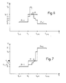
- La figure 6 est un diagramme en fonction du temps permettant d'illustrer le principe de recréation de détails fins;
- La figure 7 est un diagramme tension en fonction du temps permettant d'illustrer une décomposition en paliers.
- FIGS. 1 and 2 respectively represent the block diagrams of the transmitting part and of the receiving part of a system for the digital transmission of iconographic documents emitted and received by a Belin-type method;
- FIG. 3 is a voltage versus time diagram of an analog source signal and of the corresponding digitized signal;
- FIG. 4 is a voltage versus time diagram of a digitized signal, this diagram making it possible to present the variables;
- FIG. 5 is a voltage versus time diagram of a digitized signal in which the central pixel is broken down into sub pixels;
- FIG. 6 is a diagram as a function of time making it possible to illustrate the principle of recreating fine details;
- FIG. 7 is a voltage versus time diagram making it possible to illustrate a decomposition in stages.
Avec référence à la figure 1, le signal issu de l'émetteur 1 (par exemple une porteuse de 1800 Hz modulée en amplitude) est appliqué à l'entrée d'un amplificateur à gain variable 2 à travers un transformateur d'isolement 3.With reference to FIG. 1, the signal from the transmitter 1 (for example an amplitude modulated 1800 Hz carrier) is applied to the input of a
Au bout de trois secondes de signal blanc ininterrompu envoyé par l'émetteur 1, le circuit 4 détecte la présence de début de transmission et ajuste le gain de l'amplificateur 2 pour que celui-ci délivre un signal dont l'amplitude soit égale à la valeur maximale que puisse admettre le convertisseur analogique-numérique 5, ceci afin que le signal d'amplitude maximale correspondant au "blanc" délivré par l'émetteur 1, corresponde bien à la valeur numérique la plus élevée que puisse fournir le convertisseur analogique-numérique 5. Toutefois, dans le cas où le signal de lecture du document présenterait une amplitude de blanc,supérieure à celle déterminée à l'origine par le signal de blanc, un écrêteur peut être prévu pour aligner cette amplitude au niveau de blanc préalablement établi. Le signal déterminant le gain de l'amplificateur 2 est mémorisé de sorte que ce gain reste identique tout au long de la transmission du document.After three seconds of uninterrupted white signal sent by the
Dès que ce verrouillage de gain est réalisé, un circuit 6 génère un mot binaire redondant qui servira de signal de synchronisation à la partie réceptrice (figure 2) pour que celle-ci puisse reconnaître le début et la fin d'un mot binaire quantifiant un pixel. A la sortie de l'amplificateur 2, est relié un redresseur double alternance avec filtre passe-bas 7 destiné à démoduler le signal de luminance de la porteuse à 1800 Hz.As soon as this gain locking is achieved, a circuit 6 generates a redundant binary word which will serve as a synchronization signal to the receiving part (FIG. 2) so that the latter can recognize the start and the end of a binary word quantizing a pixel. At the output of
Le signal analogique démodulé fourni par le redresseur 7 est transmis à un convertisseur linéaire-logarithmique 8 par l'intermédiaire d'un dispositif de commutation 9.The demodulated analog signal supplied by the rectifier 7 is transmitted to a linear-
Ce convertisseur 8 a pour but de linéariser le signal de luminance. En effet, celui-ci est lié de façon exponentielle aux différents gris allant du noir au blanc, du document. Le fait de linéariser ce rapport permet de quantifier chaque pixel avec 5 bits seulement.The purpose of this
Le convertisseur 8 est relié par sa sortie à un intégrateur double 10 dont chaque section travaillant alternativement permet d'intégrer tout le signal de luminance que délivre chaque pixel. Cette méthode élimine l'incertitude d'intégration qui serait due au temps nécessaire pris par un intégrateur simple pour revenir à zéro avant chaque nouvelle intégration de signal de luminance de pixel.The
Dès que cette intégration est terminée, le signal est transféré dans un échantillonneur bloqueur 11 et stocké dans cet échantillonneur 11 le temps que le convertisseur analogique numérique 5 faisant suite ait fini sa conversion. Le signal numérique représentant la valeur du pixel est ensuite sérialisé par l'interface parallèle/ série 12 et envoyé en sortie du système vers un multiplexeur et ou un modem 13 permettant d'attaquer la ligne 14 selon les normes en vigueur.As soon as this integration is complete, the signal is transferred to a blocking
Dans cet exemple de réalisation, la fréquence horloge pilotant le convertisseur analogique - numérique 5 et l'interface parallèle/série 12, est égale à 4800 hz, fréquence fournie par le modem émetteur 13, divisé de façon synchrone par N, N étant le nombre de bits binaires composant le mot binaire quantifiant un pixel.In this exemplary embodiment, the clock frequency driving the analog-digital converter 5 and the parallel /
On obtient donc une transmission synchrone des informations binaires, c'est-à-dire sans bits supplémentaires de début et de fin.A synchronous transmission of the binary information is therefore obtained, that is to say without additional start and end bits.
Dans la partie réceptrice représentée figure 2, le signal numérique série transmise par la ligne 14. est appliqué à l'entrée d'un convertisseur/série parallèle de 5 bits (registre à décalage 16). Les signaux issus de ce convertisseur 16 sont reçus par un décodeur de mot binaire de reconnaissance 17 émis par le bloc 6 (figure 1) qui, suivant le code 18 employé, autorisera ou non.la partie réceptrice à prendre le document. Parallèlement, un décodeur de mot de synchronisation 18 déclenche sur ce mot de synchronisation, après validation 19, un signal qui est appliqué à l'entrée remise à zéro d'un compteur 20 diviseur par cinq de la fréquence horloge du modem 13 (4 800 Hz). La sortie de ce compteur 20 commande l'acquisition par le convertisseur numérique - analogique 21 du signal présent sur ses entrées. Les mots binaires appliqués au convertisseur numérique - analogique seront pris en compte de façon synchrone aux mots binaires générés par l'émetteurs.In the receiving part shown in FIG. 2, the serial digital signal transmitted by
Le signal ainsi obtenu est, à la reconstruction numérique près, l'image analogique du signal émis. Ce signal est ensuite traité par le convertisseur logarithmique/ linéaire 22, et par une unité de calcul et de traitement 23 appliquant le procédé selon l'invention. Ce signal exponentiel module ensuite une porteuse par exemple à 1800 Hz, dans le modulateur 25, et le signal est dirigé vers l'appareil restitueur 24 par l'intermédiaire d'un transformateur d'isolement 26. Ce signal est donc identique au signal analogique modulé qui a été délivré par l'émetteur 1.The signal thus obtained is, apart from the digital reconstruction, the analog image of the signal transmitted. This signal is then processed by the logarithmic /
Afin d'éviter les interférences qui se traduisent par des moirages sur le document reconstitué le modulateur 25 est asservi au signal d'horloge du modem 13.In order to avoid interference which results in moiré patterns on the reconstituted document, the
Quand l'appareil émetteur a fini l'analyse du document, le signal à 1800 Hz disparait. A ce moment un circuit 27 de détection image, court-circuite la sortie du convertisseur 22 de sorte que le niveau de modulation du circuit 25 soit alors à -50 dB, (bloc 27') l'appareil restitueur ne prenant un signal qu'au-dessus de -37 dB, enregistre alors la fin de transmission.When the sending device has finished analyzing the document, the 1800 Hz signal disappears. At this moment an
Il convient de noter que dans le système de transmission précédemment décrit, la lecture ligne par ligne des documents peut être réalisée selon un autre principe que celui du procédé "BELIN".It should be noted that in the transmission system described above, the line-by-line reading of the documents can be carried out according to another principle than that of the "BELIN" process.
Par ailleurs, un avantage important du système selon l'invention est qu'il autorise des fréquences d'horloge variées sans que le fonctionnement du système se trouve pertubé.Furthermore, an important advantage of the system according to the invention is that it allows various clock frequencies without disturbing the operation of the system.
En outre la réalisation de ce système de transmission peut être effectuée à l'aide de microprocesseur#In addition, the realization of this transmission system can be carried out using microprocessor #
Dans ce cas l'ordre. des traitements effectués sur le signal se trouve modifié de la façon suivante :
- - dans la partie réceptrice, tous les traitements effectués sur le signal s'effectueront en amont du convertisseur numérique-
analogique 21; - - dans la partie émettrice, les traitements effectués sur le signal s'effectueront en aval du convertisseur analogique numérique 5.
- - in the receiving part, all the processing carried out on the signal will be carried out upstream of the digital-
analog converter 21; - - in the transmitting part, the processing carried out on the signal will be carried out downstream of the analog-to-digital converter 5.
On notera tout d'abord que le diagramme de la figure 1 a été représenté pour illustrer le fait que, comme précédemment mentionné durant le temps d'intégration d'un pixel, il ne peut y avoir plus de deux intersections du signal analogique (signal source analogique z(t) avec sa valeur moyenne (signal numérisé Z (t).).It will first be noted that the diagram of FIG. 1 has been represented to illustrate the fact that, as previously mentioned during the integration time of a pixel, there cannot be more than two intersections of the analog signal (signal analog source z (t) with its mean value (digitized signal Z (t).).
On rappelle à ce sujet que ces deux signaux satisfont à la relation suivante :
- t4 représente les instants d'échantillonnage et avec

- f étant la fréquence d'échantillonnage.
- t 4 represents the sampling instants and with
- f being the sampling frequency.
Le nombre de pixels pris en compte pour le traitement du signal, dans les figures 4 et 5, a été chàisi égal à 7, ce qui semble correspondre au meilleur compromis entre l'efficacité et la complexité de l'algorithme de traitement.The number of pixels taken into account for signal processing, in Figures 4 and 5, has been equal to 7, which seems to correspond to the best compromise between the efficiency and the complexity of the processing algorithm.
Toutefois, sur ces 7 pixels P-3, P-2, P-1, P, P+1, P+2, P+3, les pixels les plus significatifs sont les cinq pixels centraux P-2, P-1, P, P+1,P+2, les deux pixels d'extrémités P-3, P+3 ne servant que dans un nombre de cas limités.However, of these 7 pixels P-3, P-2, P-1, P, P + 1, P + 2, P + 3, the most significant pixels are the five central pixels P-2, P-1, P, P + 1, P + 2, the two end pixels P-3, P + 3 being used only in a limited number of cases.
Il convient de souligner que, réduit à trois pixels (P-1, P, P+1), le traitement, bien que plus faible, apporte déjà une forte amélioration de la qualité du signal restitué et de la reproduction de l'image. Un tel traitement sera, de toutes façons, décrit dans la suite de la description.It should be emphasized that, reduced to three pixels (P-1, P, P + 1), the processing, although weaker, already brings a strong improvement in the quality of the restored signal and the reproduction of the image. Such processing will, in any case, be described in the following description.
Les variables intervenant dans le traitement du signal numérisé représenté figures 2 et 3 sont les suivantes :
- - la fréquence de base φ choisie par exemple à 4 800 Hz,
- - le nombre p de pixels pris en compte qui est 7,
- - le nombre m de sous pixels du pixel central P qui est égal à 5,
- - le nombre n de bits de quantification qui est pris égal à 5,
- - les amplitudes absolues des pixels pris en compte qui seront notées dans l'ordre ao, a, b, c, d, e, eo,
- - les écarts entre les niveaux de quantification qui seront notés αo,α, x, y, β,βo, ces écarts satisfaisant aux relations :


- - l'amplitude Cj des 5 sous pixels créés pour le traitement du pixel central P dont l'amplitude absolue est C,
- - the basic frequency φ chosen for example at 4,800 Hz,
- - the number p of pixels taken into account which is 7,
- - the number m of sub pixels of the central pixel P which is equal to 5,
- - the number n of quantization bits which is taken equal to 5,
- - the absolute amplitudes of the pixels taken into account which will be noted in order a o , a, b, c, d, e, e o ,
- - the differences between the quantification levels which will be noted α o , α, x, y, β, βo, these differences satisfying the relationships:
- the amplitude Cj of the 5 sub-pixels created for the processing of the central pixel P whose absolute amplitude is C,
Cj = c1, c2, c3, c4, c5. C j = c 1 , c 2 , c 3 , c 4 , c 5 .
On notera tout d'abord que les écarts x et y définiront le type de traitement à appliquer alors que α et β représenteront des paramètres ; on n'utilise αo et βo que dans des cas particuliers. Afin de maintenir les valeurs calculées entre les niveaux correspondant au noir photo et au blanc photo, on utilise l'amplitude C du pixel P pour pondérer l'efficacité du traitement. Ce dernier étant répétitif, il faut souligner que les valeurs prises en compte à un instant t seront décalées d'un pixel pour le traitement correspondant à celui de l'instant suivant, d'où les égalités :![]()
![]()
-
1. Dans le cas où x = O, aucune modification n'est à apporter, c'est-à-dire que quel que soit j compris dans l'intervalle [1, 5J , on aura l'égalité :
Cj = C1. In the case where x = O, no modification is to be made, that is to say that whatever j is included in the interval [1, 5J, we will have the equality:
Cj = C -
2. Dans le cas où x est différent de zéro, le type de traitement variera en fonction de la valeur et du signe du produit x.y et du produit β.X.
- a) Dans le cas où x.y est égale à 0 :
- - si β.x = 0 il n'y aura de modification à apporter que si x = + 1, auquel cas, quel que soit j compris dans l'intervalle [1,5] la relation suivante devra être satisfaite :

- - si β.x>0 aucune modification ne sera apportée, c'est-à-dire que quel que soit j compris dans l'intervalle [1, 5J l'égalité Cj = C sera réalisée,
- - si β.x < 0 on applique alors le traitement "recréation de détails fins" qui sera décrit ci-après, en regard de la figure 4, pour les deux pixels P et P+l à la fois, car on se trouve alors en présence de points doubles C = d.
- - si β.x = 0 il n'y aura de modification à apporter que si x = + 1, auquel cas, quel que soit j compris dans l'intervalle [1,5] la relation suivante devra être satisfaite :
- b) Dans le cas où x.y < 0 on applique le traitement "recréation de détails fins" pour le pixel P et, éventuellement, dans certains cas, pour les pixels P et P+l.
- c) Dans le cas où x.y) 0 on applique un traitement "décomposition en paliers" qui sera décrit dans la suite en regard de la figure 5, afin de favoriser la transition entre les pixels P-1 et P+1.
- a) In the case where xy is equal to 0:
- - if β.x = 0 there will be no modification to bring that if x = + 1, in which case, whatever j is in the interval [1,5] the following relation must be satisfied:
- - if β.x> 0 no modification will be made, that is to say that whatever j is included in the interval [1, 5J the equality Cj = C will be achieved,
- - if β.x <0 then we apply the "recreation of fine details" processing which will be described below, with reference to FIG. 4, for the two pixels P and P + l at the same time, since we then find ourselves in the presence of double points C = d.
- - if β.x = 0 there will be no modification to bring that if x = + 1, in which case, whatever j is in the interval [1,5] the following relation must be satisfied:
- b) In the case where xy <0, the "fine detail recreation" treatment is applied for the pixel P and, possibly, in some cases, for the pixels P and P + 1.
- c) In the case where xy) 0, a “decomposition in stages” treatment is applied which will be described below with reference to FIG. 5, in order to promote the transition between the pixels P-1 and P + 1.
- a) Dans le cas où x.y est égale à 0 :
On constate donc qu'il suffit de définir deux traitements distincts qui sont :
- - La "recréation de détails fins" (x.y<0 et point double).
- - La "décomposition en paliers" (x.y>0).
- - "recreating fine details" (xy <0 and double point).
- - The "decomposition in stages"(xy> 0).
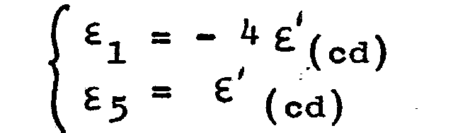
Les 5 sous pixels recréés représentent la décomposition de la transition entre le niveau b et le niveau d. Ces sous niveaux ont des valeurs déterminées par des coefficients fonction des écarts x, y, α, β. On notera que si α = 0, ou β = 0 on les remplace respectivement dans les calculs par αo et βo.The 5 sub-pixels recreated represent the decomposition of the transition between level b and level d. These sub-levels have values determined by coefficients which are a function of the deviations x, y, α, β. It will be noted that if α = 0, or β = 0 they are replaced respectively in the calculations by α o and β o .
Comme le traitement est itératif et qu'il ne concerne qu'un pixel à la fois, il faut que le recoupement entre les pixels représente une transition logique.As the processing is iterative and that it only concerns one pixel at a time, the overlap between the pixels must represent a logical transition.
On a donc été amené à définir le point correspondant au passage entre deux pixels successifs. Pour le traitement du pixel P, ce point Pi, aura pour coordonnées :
Ce point correspond alors au meilleur passage de courbe entre le pixel P-1 et le pixel P.This point then corresponds to the best curve passage between pixel P-1 and pixel P.
De la même façon, on peut définir le point de passage optimal pour la transition entre les pixels (c) et (d). Par rapport à (d) ce point P(i+1) aura pour coordonnées :
- ti+1 en abscisse

- t i + 1 on the abscissa
.Pour le traitement du pixel P, il est nécessaire de connaître les coordonnées de ce point Pi+1 par rapport à P. Ce simple changement d'origine est obtenu en posant : d = C + y d'où :
Maintenant que l'on connaît les deux valeurs ε(bc) et ε'(cd) on a borné les variations des sous pixels extrêmes et on peut, en fonction du rapport ![]()
![]()
Ces cas sont déterminés par les deux tests suivants dans lesquels il faut souligner que si α ou β sont nuls ils ne seront pas remplacés par αo ou βo .
- . si α.x < on remplace ε (bc) par x lorsque le rapport ε(ab) / ε' (bc) sera supérieur à 1,4.
- . si y. β < o on remplace ε' (cd) par y lorsque le rapport ε'(de)/ε(cd) sera supérieur à 1,4.
- . if α.x <we replace ε (bc) by x when the ratio ε (ab) / ε ' (bc) will be greater than 1.4.
- . if there. β <o we replace ε ' (cd) by y when the ratio ε' (de) / ε (cd) will be greater than 1.4.
Il est évident que ces substitutions seront faites dans les calculs et les équations suivantsIt is obvious that these substitutions will be made in the following calculations and equations
Par convention on pose : ∀j ∈[1,5], Cj = C + εj 5 on a donc j ![]()


![]()
![]()


![]()


![]()

![]()
![]()
![]()
![]()
![]()
![]()
![]()
Pour ce traitement on reprend le même principe que précédemment, c'est-à-dire qu'on calcule les coordonnées des points de passage optimum : Pi et Pi+1·

De la même façon, l'amplitude des sous pixels va dépendre directement des valeursε(bc) et ε'(cd) mais on doit tenir compte de l'amplitude absolue C du pixel P afin de limiter le traitement de façon à maintenir les valeurs des sous pixels recréés entre les tensions correspondant respectivement au noir photo et au blanc photo (Δ sera le coefficient de pondération). Il faut remarquer que, comme précédemment, il faut rajouter un test sur (y.β) et (x.α) et si α ou β sont nuls ils seront remplacés dans les calculs par respectivement αo ou βo.
- - si (y.β<0) ce qui correspondra, pour le pixel P+1, à un traitement du type "recréation de détails fins" on doit étudier le rapport ε'(de)/ε(cd) afin de situer le maximum du pic à recréer.
- - if (y.β <0) which will correspond, for the pixel P + 1, to a processing of the "recreating fine details" type, the ratio ε ' (of) / ε (cd) must be studied in order to locate the maximum of the peak to be recreated.
Si ce rapport est supérieur à 1,4 on devra remplacer dans les calculs qui suivent ε(cd) par y.If this ratio is greater than 1.4, we must replace in the following calculations ε (cd) by y.
- si (x.α<0) on remplacera, de la même façon, εbc par -x lorsque le rapport ε(ab)/ε'(bc) sera supérieur à 1,4.- if (x.α <0) we will replace, in the same way, ε bc by -x when the ratio ε (ab) / ε ' (bc) will be greater than 1.4.
Dans tous les calculs suivants on aura les Cj définis par :![]()
![]()
Le traitement proprement dit s'effectue alors comme suit
![]()
![]()


![]()

![]()
![]()

![]()

![]()
![]()

![]()
![]()

![]()
![]()
![]()
![]()
![]()
![]()
![]()
![]()
![]()
![]()
Deux cas possibles doivent alors être envisagés : si y.β≤o![]()

![]()
Ce traitement particulier de deux pixels simultanément sera traité dans la partie suivante :This particular treatment of two pixels simultaneously will be treated in the following part:
Ce traitement complète le cas ci-dessus lorsque l'on répond à la condition y.β> O. Les cinq sous pixels recréés pour le pixel (d) vont s'écrire :![]()
![]()
Pour parfaire le calcul, on calcule ε'(de) = 
![]()
![]()
![]()
![]()
![]()

![]()
![]()
![]()
![]()
![]()
Les points de référence utiles sont maintenant![]()

![]()
![]()
![]()
![]()
![]()
![]()
![]()
- · Soit M la valeur correspondant à un blanc photo, afin de pondérer les valeurs des Cj il faut calculerΔ, facteur de pondération.· Let M be the value corresponding to a blank photo, in order to weight the values of Cj it is necessary to calculate Δ, weighting factor.
-
- si x > 0, on compare le plus grand écart εj avec la différence M -C :


-
- si x(O, on compare le plus grand écart -εj avec C:


En conclusion, trois remarques peuvent être effectuées
- - Les domaines d'application qui ont servi de limites pour l'étude des variations d'amplitude des sous pixels sont des résultats d'expériences et de calculs préliminaires qui prennent en compte les caractéristiques fondamentales d'un document iconographique. Les variations d'amplitudes des différents sous pixels ont été appro- ximées, par morceaux, à des fonctions du premier degré et ce afin de faciliter le traitement qu'il soit analogique ou numérique. En modifiant les dérivées premières de ces fonctions, on peut jouer facilement sur l'efficacité du traitement tout en conoervant la même valeur moyenne de densité.
- - La deuxième remarque que l'on peut apporter concerne l'immunité aux parasites. La bande passante du signal analogique étant restreinte à environ 800 Hz, on peut en déduire que certaines transitions sont interdites et que l'observation du signal numérique, à la réception, permet d'éliminer la plupart des parasites gênants et présentant des transitions anormales comme, par exemple, les points foncés sur un fond clair. Pour une bande passante déterminée, il existe un seuil S qui ne peut être dépassé par la somme |x| +|y| quand x.y<0.
- - The fields of application which served as limits for the study of the amplitude variations of the sub pixels are the results of experiments and preliminary calculations which take into account the fundamental characteristics of an iconographic document. The amplitude variations of the different sub-pixels have been approximated, piecewise, to first degree functions in order to facilitate processing, whether analog or digital. By modifying the first derivatives of these functions, one can easily play on the efficiency of the treatment while maintaining the same average density value.
- - The second remark that can be made concerns immunity to parasites. Since the bandwidth of the analog signal is limited to approximately 800 Hz, it can be inferred that certain transitions are prohibited and that observation of the digital signal, on reception, makes it possible to eliminate most of the annoying parasites and exhibiting abnormal transitions such as , for example, dark dots on a light background. For a given bandwidth, there is a threshold S which cannot be exceeded by the sum | x | + | y | when xy <0.
On constate, à l'expérience, que dans le cas où n = 5, ce seuil peut être pris égal à 15.
- - Il faut, comme dernière remarque, rappeler que le signal obtenu à la sortie du système de traitement servira à moduler en amplitude un signal à 1 800 Hz afin de pouvoir brancher un récepteur photo classique.
Le 1 800 Hz sera asservi sur la fréquence mère φ issue du modem afin d'éviter les interférences et effectue un filtrage naturel du signal modulant.
- - As a last remark, it should be remembered that the signal obtained at the output of the processing system will be used to amplify a signal at 1,800 Hz in order to be able to connect a conventional photo receiver. The 1,800 Hz will be slaved to the mother frequency φ from the modem in order to avoid interference and performs natural filtering of the modulating signal.
Dans ce cas, les seules valeurs prises en compte sont alors x et y qui jouent un rôle symétrique car si l'on inverse x et y il suffit de changer l'ordre des Cj. x.y = 0 - les valeurs de C sont inchangées - Cj = C. x.y > 0 - tableau (l) - "transitions".In this case, the only values taken into account are then x and y which play a symmetrical role because if we reverse x and y it suffices to change the order of C j . xy = 0 - the values of C are unchanged - Cj = C. xy> 0 - table (l) - "transitions".
x.y < 0 - tableau (2) - "détails" .x.y <0 - table (2) - "details".
Tableaux de traitement utilisés :

Quand x>y il suffit d'inverser l'ordre des Ci et de remplacer x par y dans le tableau 1.

Dans le cas où y < 0 et x > 0, il suffit d'inverser l'ordre des Ci et de remplacer x par y dans le tableau 2. Le signal de sortie sera borné par les niveaux correspondant respectivement au blanc photo et au noir photo.In the case where y <0 and x> 0, it suffices to reverse the order of the Ci and to replace x by y in table 2. The output signal will be bounded by the levels corresponding respectively to the photo white and to the black Photo.
Claims (18)


Priority Applications (1)
| Application Number | Priority Date | Filing Date | Title |
|---|---|---|---|
| AT82400826T ATE10150T1 (en) | 1981-05-08 | 1982-05-05 | METHOD AND DEVICE FOR RECONSTRUCTING AN ANALOG BRIGHTNESS SIGNAL FROM A NUMERICAL SIGNAL. |
Applications Claiming Priority (4)
| Application Number | Priority Date | Filing Date | Title |
|---|---|---|---|
| FR8109240A FR2505588B1 (en) | 1981-05-08 | 1981-05-08 | SYSTEM FOR THE DIGITAL TRANSMISSION OF INFORMATION IN THE FORM OF ANALOG SIGNALS |
| FR8109240 | 1981-05-08 | ||
| FR8113482 | 1981-07-09 | ||
| FR8113482A FR2509557B1 (en) | 1981-07-09 | 1981-07-09 | METHOD FOR RECREATING AN ANALOGUE LUMINANCE SIGNAL FROM A DIGITAL SIGNAL |
Publications (2)
| Publication Number | Publication Date |
|---|---|
| EP0065454A1 true EP0065454A1 (en) | 1982-11-24 |
| EP0065454B1 EP0065454B1 (en) | 1984-10-31 |
Family
ID=26222384
Family Applications (1)
| Application Number | Title | Priority Date | Filing Date |
|---|---|---|---|
| EP82400826A Expired EP0065454B1 (en) | 1981-05-08 | 1982-05-05 | Method and device for reconstructing an analogue luminance signal from a digital signal |
Country Status (4)
| Country | Link |
|---|---|
| US (1) | US4670792A (en) |
| EP (1) | EP0065454B1 (en) |
| CA (1) | CA1189181A (en) |
| DE (1) | DE3261118D1 (en) |
Families Citing this family (5)
| Publication number | Priority date | Publication date | Assignee | Title |
|---|---|---|---|---|
| US4870497A (en) * | 1988-01-22 | 1989-09-26 | American Telephone And Telegraph Company | Progressive transmission of high resolution two-tone facsimile images |
| US4952921A (en) * | 1988-06-09 | 1990-08-28 | Rockwell International Corporation | Graphic dot flare apparatus |
| US4926267A (en) * | 1989-05-26 | 1990-05-15 | Nynex Corporation | Reproduction of halftone original with reduced moire |
| FI20001913A (en) | 2000-08-30 | 2002-03-01 | Nokia Mobile Phones Ltd | Procedure and arrangements for reducing disturbance |
| US7645300B2 (en) | 2004-02-02 | 2010-01-12 | Visiogen, Inc. | Injector for intraocular lens system |
Citations (13)
| Publication number | Priority date | Publication date | Assignee | Title |
|---|---|---|---|---|
| US2921124A (en) * | 1956-12-10 | 1960-01-12 | Bell Telephone Labor Inc | Method and apparatus for reducing television bandwidth |
| US3071727A (en) * | 1961-05-08 | 1963-01-01 | Bell Telephone Labor Inc | Bandwidth reduction system |
| US3673322A (en) * | 1970-05-28 | 1972-06-27 | Shintron Co Inc | Facsimile transmission system |
| US3678388A (en) * | 1970-12-14 | 1972-07-18 | Us Navy | Ground station system for retransmitting satellite facsimile signals over digital data links |
| US3688039A (en) * | 1969-08-05 | 1972-08-29 | Nippon Electric Co | Digital signal reception system |
| FR2125532A1 (en) * | 1971-02-16 | 1972-09-29 | Graphic Sciences Inc | |
| DE2402513A1 (en) * | 1974-01-19 | 1975-07-31 | Licentia Gmbh | Binary coded video signal compression method - with analogue signals sampled quantised and coded into words of length N |
| US3902008A (en) * | 1972-10-04 | 1975-08-26 | Ricoh Kk | Data transmission system |
| FR2374796A1 (en) * | 1976-12-19 | 1978-07-13 | Ricoh Kk | FAC-SIMILE TRANSCEIVER |
| FR2396478A1 (en) * | 1977-06-30 | 1979-01-26 | Siemens Ag | INFORMATION TRANSMISSION SYSTEM |
| US4153916A (en) * | 1976-11-12 | 1979-05-08 | Fujitsu Limited | Facsimile communication system and method |
| WO1980000646A1 (en) * | 1978-09-18 | 1980-04-03 | Massachusetts Inst Technology | Image coding by selective addition of pseudo-random noise to portions of video signal |
| WO1980000645A1 (en) * | 1978-09-19 | 1980-04-03 | Western Electric Co | Digital encoder for facsimile transmission |
Family Cites Families (7)
| Publication number | Priority date | Publication date | Assignee | Title |
|---|---|---|---|---|
| US3719600A (en) * | 1971-02-08 | 1973-03-06 | Exxon Research Engineering Co | Lubricant composition containing polycarboxylic acid |
| JPS54150022A (en) * | 1978-05-18 | 1979-11-24 | Ricoh Co Ltd | Method and apparatus for picture encoding reproduction |
| US4349846A (en) * | 1979-04-17 | 1982-09-14 | Ricoh Company, Ltd. | Picture processing method |
| US4280144A (en) * | 1979-12-03 | 1981-07-21 | International Business Machines Corporation | Coarse scan/fine print algorithm |
| JPS56102853A (en) * | 1980-01-21 | 1981-08-17 | Dainippon Screen Mfg Co Ltd | Metho for pretreating image signal of image copying apparatus |
| CH637513A5 (en) * | 1980-06-16 | 1983-07-29 | Radioelectrique Comp Ind | APPARATUS FOR PHOTOGRAPHIC RECEPTION OF IMAGES TRANSMITTED BY MEANS OF A MODULATED ELECTRICAL SIGNAL. |
| US4389677A (en) * | 1980-12-08 | 1983-06-21 | Ncr Canada Ltd - Ncr Canada Ltee | Method and apparatus for removing erroneous elements from digital images |
-
1982
- 1982-04-28 CA CA000401837A patent/CA1189181A/en not_active Expired
- 1982-05-05 EP EP82400826A patent/EP0065454B1/en not_active Expired
- 1982-05-05 DE DE8282400826T patent/DE3261118D1/en not_active Expired
- 1982-05-07 US US06/376,192 patent/US4670792A/en not_active Expired - Fee Related
Patent Citations (13)
| Publication number | Priority date | Publication date | Assignee | Title |
|---|---|---|---|---|
| US2921124A (en) * | 1956-12-10 | 1960-01-12 | Bell Telephone Labor Inc | Method and apparatus for reducing television bandwidth |
| US3071727A (en) * | 1961-05-08 | 1963-01-01 | Bell Telephone Labor Inc | Bandwidth reduction system |
| US3688039A (en) * | 1969-08-05 | 1972-08-29 | Nippon Electric Co | Digital signal reception system |
| US3673322A (en) * | 1970-05-28 | 1972-06-27 | Shintron Co Inc | Facsimile transmission system |
| US3678388A (en) * | 1970-12-14 | 1972-07-18 | Us Navy | Ground station system for retransmitting satellite facsimile signals over digital data links |
| FR2125532A1 (en) * | 1971-02-16 | 1972-09-29 | Graphic Sciences Inc | |
| US3902008A (en) * | 1972-10-04 | 1975-08-26 | Ricoh Kk | Data transmission system |
| DE2402513A1 (en) * | 1974-01-19 | 1975-07-31 | Licentia Gmbh | Binary coded video signal compression method - with analogue signals sampled quantised and coded into words of length N |
| US4153916A (en) * | 1976-11-12 | 1979-05-08 | Fujitsu Limited | Facsimile communication system and method |
| FR2374796A1 (en) * | 1976-12-19 | 1978-07-13 | Ricoh Kk | FAC-SIMILE TRANSCEIVER |
| FR2396478A1 (en) * | 1977-06-30 | 1979-01-26 | Siemens Ag | INFORMATION TRANSMISSION SYSTEM |
| WO1980000646A1 (en) * | 1978-09-18 | 1980-04-03 | Massachusetts Inst Technology | Image coding by selective addition of pseudo-random noise to portions of video signal |
| WO1980000645A1 (en) * | 1978-09-19 | 1980-04-03 | Western Electric Co | Digital encoder for facsimile transmission |
Non-Patent Citations (2)
| Title |
|---|
| NATIONAL TELECOMMUNICATIONS CONFERENCE NTC 73, 26-28 novembre 1973, pages 12C-1-12C-6, édité par "The Institute of electrical and electronics engineers", Atlanta, Georgia (USA); * |
| RUNDFUNKTECHNISCHE MITTEILLUNGEN, vol. 19, no. 5, septembre 1975, pages 194-199, Munich (DE); * |
Also Published As
| Publication number | Publication date |
|---|---|
| US4670792A (en) | 1987-06-02 |
| DE3261118D1 (en) | 1984-12-06 |
| EP0065454B1 (en) | 1984-10-31 |
| CA1189181A (en) | 1985-06-18 |
Similar Documents
| Publication | Publication Date | Title |
|---|---|---|
| EP0098763B1 (en) | Methods and devices for visual telecommunication, especially for use by the deaf | |
| EP0266241B1 (en) | Method for transforming an original video image having multiple grey levels into a binary image | |
| FR2842691A1 (en) | METHOD AND DEVICE FOR TRANSFORMING A DIGITAL SIGNAL | |
| FR2590099A1 (en) | METHOD FOR TRANSMITTING A HIGH DEFINITION IMAGE THROUGH A NARROW BAND COMMUNICATION CHANNEL | |
| FR2889382A1 (en) | Multidimensional digital signal e.g. digital image, filtering method for e.g. coding device, involves obtaining filtering value of filtered sample in selecting one value among simulated filtering values of sample based on preset criterion | |
| EP0595710A1 (en) | Method and apparatus for subband decomposition and reconstruction of a digital signal, and corresponding device | |
| FR2817440A1 (en) | INSERTION OF MESSAGES IN DIGITAL DATA | |
| EP0921496B1 (en) | Image processing method in which noise is signal dependent | |
| EP0065454B1 (en) | Method and device for reconstructing an analogue luminance signal from a digital signal | |
| FR2713423A1 (en) | Differential encoder and decoder for trellis coded VCD-8 modulation by the pragmatic approach. | |
| EP0117161A1 (en) | Method and device for the digital coding of a picture, in particular a television picture | |
| EP2345238B1 (en) | Method for the three-dimensional digitisation of books using terahertz radiation | |
| FR2790124A1 (en) | METHOD OF MARKING A MULTIMEDIA DOCUMENT, SUCH AS AN IMAGE, BY GENERATING AN EXTERNAL FOOTPRINT | |
| FR2739953A1 (en) | METHOD AND APPARATUS FOR TRANSFORMING IMAGE DATA | |
| CA2108663C (en) | Filtering method and device for reducing digital audio signal pre-echoes | |
| EP0542623A1 (en) | Process and device for acquiring and processing radioscopic images | |
| WO2018083266A1 (en) | Method and device for digital image restoration | |
| FR2755564A1 (en) | Image data coding using adjacent pixels in successive scan lines | |
| FR2509557A1 (en) | Analogue luminance signal recovery from digital transmission - by using D=A converter and signal processor for decomposing pixel into components dependent on neighbouring pixels | |
| FR2551210A1 (en) | METHOD OF CONTROLLING A NETWORK | |
| EP0812070B1 (en) | Method and device for compression encoding of a digital signal | |
| FR2747869A1 (en) | METHOD AND DEVICE FOR CORRECTING TRANSMISSION ERRORS OF NUMBER SUITES | |
| FR2717927A1 (en) | Compression, palette generation, emission and reception of colour images | |
| EP1271473B1 (en) | System and method for PRE-AND POST-PROCESSING of an audio signal for transmission over a strongly distorted channel | |
| FR2805941A1 (en) | JPEG fixed image compression bit ordering method for a state word representing the state of a coefficient at the moment of entropy coding with several passes of the coefficient |
Legal Events
| Date | Code | Title | Description |
|---|---|---|---|
| PUAI | Public reference made under article 153(3) epc to a published international application that has entered the european phase |
Free format text: ORIGINAL CODE: 0009012 |
|
| AK | Designated contracting states |
Designated state(s): AT BE CH DE GB IT LU NL SE |
|
| 17P | Request for examination filed |
Effective date: 19830402 |
|
| ITF | It: translation for a ep patent filed |
Owner name: STUDIO GLP S.R.L. |
|
| GRAA | (expected) grant |
Free format text: ORIGINAL CODE: 0009210 |
|
| AK | Designated contracting states |
Designated state(s): AT BE CH DE GB IT LI LU NL SE |
|
| REF | Corresponds to: |
Ref document number: 10150 Country of ref document: AT Date of ref document: 19841115 Kind code of ref document: T |
|
| REF | Corresponds to: |
Ref document number: 3261118 Country of ref document: DE Date of ref document: 19841206 |
|
| PLBE | No opposition filed within time limit |
Free format text: ORIGINAL CODE: 0009261 |
|
| STAA | Information on the status of an ep patent application or granted ep patent |
Free format text: STATUS: NO OPPOSITION FILED WITHIN TIME LIMIT |
|
| 26N | No opposition filed | ||
| ITTA | It: last paid annual fee | ||
| EPTA | Lu: last paid annual fee | ||
| EAL | Se: european patent in force in sweden |
Ref document number: 82400826.2 |
|
| PGFP | Annual fee paid to national office [announced via postgrant information from national office to epo] |
Ref country code: LU Payment date: 19950401 Year of fee payment: 14 |
|
| PGFP | Annual fee paid to national office [announced via postgrant information from national office to epo] |
Ref country code: SE Payment date: 19950420 Year of fee payment: 14 |
|
| PGFP | Annual fee paid to national office [announced via postgrant information from national office to epo] |
Ref country code: GB Payment date: 19950424 Year of fee payment: 14 |
|
| PGFP | Annual fee paid to national office [announced via postgrant information from national office to epo] |
Ref country code: BE Payment date: 19950510 Year of fee payment: 14 |
|
| PGFP | Annual fee paid to national office [announced via postgrant information from national office to epo] |
Ref country code: CH Payment date: 19950518 Year of fee payment: 14 |
|
| PGFP | Annual fee paid to national office [announced via postgrant information from national office to epo] |
Ref country code: DE Payment date: 19950524 Year of fee payment: 14 |
|
| PGFP | Annual fee paid to national office [announced via postgrant information from national office to epo] |
Ref country code: NL Payment date: 19950531 Year of fee payment: 14 Ref country code: AT Payment date: 19950531 Year of fee payment: 14 |
|
| PG25 | Lapsed in a contracting state [announced via postgrant information from national office to epo] |
Ref country code: LU Free format text: LAPSE BECAUSE OF NON-PAYMENT OF DUE FEES Effective date: 19960505 Ref country code: GB Effective date: 19960505 Ref country code: AT Effective date: 19960505 |
|
| PG25 | Lapsed in a contracting state [announced via postgrant information from national office to epo] |
Ref country code: SE Effective date: 19960506 |
|
| PG25 | Lapsed in a contracting state [announced via postgrant information from national office to epo] |
Ref country code: LI Effective date: 19960531 Ref country code: CH Effective date: 19960531 Ref country code: BE Effective date: 19960531 |
|
| BERE | Be: lapsed |
Owner name: ORGANISME AUTONOME DOTE DE LA PERSONNALITE CIVILE Effective date: 19960531 |
|
| PG25 | Lapsed in a contracting state [announced via postgrant information from national office to epo] |
Ref country code: NL Effective date: 19961201 |
|
| GBPC | Gb: european patent ceased through non-payment of renewal fee |
Effective date: 19960505 |
|
| REG | Reference to a national code |
Ref country code: CH Ref legal event code: PL |
|
| PG25 | Lapsed in a contracting state [announced via postgrant information from national office to epo] |
Ref country code: DE Effective date: 19970201 |
|
| EUG | Se: european patent has lapsed |
Ref document number: 82400826.2 |
|
| NLV4 | Nl: lapsed or anulled due to non-payment of the annual fee |
Effective date: 19961201 |