EP0058059A1 - Video tape recording and reproducing apparatus - Google Patents
Video tape recording and reproducing apparatus Download PDFInfo
- Publication number
- EP0058059A1 EP0058059A1 EP19820300569 EP82300569A EP0058059A1 EP 0058059 A1 EP0058059 A1 EP 0058059A1 EP 19820300569 EP19820300569 EP 19820300569 EP 82300569 A EP82300569 A EP 82300569A EP 0058059 A1 EP0058059 A1 EP 0058059A1
- Authority
- EP
- European Patent Office
- Prior art keywords
- tape
- recording
- magnetic
- temporary stop
- reproducing
- Prior art date
- Legal status (The legal status is an assumption and is not a legal conclusion. Google has not performed a legal analysis and makes no representation as to the accuracy of the status listed.)
- Granted
Links
Images

Classifications
-
- G—PHYSICS
- G11—INFORMATION STORAGE
- G11B—INFORMATION STORAGE BASED ON RELATIVE MOVEMENT BETWEEN RECORD CARRIER AND TRANSDUCER
- G11B15/00—Driving, starting or stopping record carriers of filamentary or web form; Driving both such record carriers and heads; Guiding such record carriers or containers therefor; Control thereof; Control of operating function
- G11B15/02—Control of operating function, e.g. switching from recording to reproducing
- G11B15/026—Control of operating function, e.g. switching from recording to reproducing by using processor, e.g. microcomputer
-
- G—PHYSICS
- G11—INFORMATION STORAGE
- G11B—INFORMATION STORAGE BASED ON RELATIVE MOVEMENT BETWEEN RECORD CARRIER AND TRANSDUCER
- G11B15/00—Driving, starting or stopping record carriers of filamentary or web form; Driving both such record carriers and heads; Guiding such record carriers or containers therefor; Control thereof; Control of operating function
- G11B15/18—Driving; Starting; Stopping; Arrangements for control or regulation thereof
- G11B15/20—Moving record carrier backwards or forwards by finite amounts, i.e. backspacing, forward spacing
Definitions
- This invention relates to a video tape recording and reproducing apparatus using rotary magnetic heads, and more particularly to such apparatus which prevents a magnetic tape and the rotary heads from being damaged when temporarily stopped for a long time during the recording or reproducing modes and is easy to use for users of VTR.
- the stop When video tape is temporarily stopped during the recording or reproducing modes, the stop, if for a long time, leads to the rotary magnetic heads scanning the same portion of the magnetic tape, thereby creating the problem that the magnetic layer of the tape peels off leading to tape damage or adhesion of the peeled layer to the magnetic heads. Therefore, conventionally, the temporary stop, after the lapse of a given time, is often released to put the VTR into a stop mode condition. Such a remedy, however, requires reloading of the magnetic tape on the rotary magnetic head drum for restarting the recording or reproducing, or the head shifts from the position where it has previously recorded or reproduced the tape.
- An object of the invention is to provide a video tape recording and reproducing apparatus which has improved means for the control for a temporary stop of magnetic tape during the recording or reproducing mode.
- the present invention provides a video signal recording and reproducing apparatus for a video tape recorder which loads a magnetic tape on a rotary magnetic head drum so as to record or reproduce video signals by magnetic heads, characterized in that said apparatus has a tape transportation means which temporarily stops transportation of said tape for a time T while keeping rotary magnetic heads rotating during recording or reproducing, allows said tape to advance a little after the lapse of said time T from the position of the temporary stop, and then temporarily stops said tape for said time T thereby to prevent the magnetic heads and the tape from damaging.
- a magnetic tape is wound on a rotary head drum and is recorded, while travelling, by rotary magnetic heads to produce sloping tracks in the tape, the reproduction being performed by scanning the recording tracks with the magnetic heads.
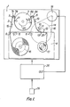
- Figure 1 is a plan view of such a mechanism in which a mechanical chassis 1 has disposed thereon a rotary head drum 3 and tape cassette 4 containing tape reels 16, 17.
- Figure 1 shows a recording or reproducing condition, in which a magnetic tape 2 is drawn out of the cassette 4 and loaded on the rotary head drum 3 through loading supports 5 and 6 having guide posts 7A, 7B, 8A and 8B respectively (loading supports 5 and 6 move from within the cassette as shown in dotted lines to the position shown in full lines).
- the magnetic tape 2 is drawn off the supplying reel 16 and is wound on the take-up reel 17 via a guide post 9, the guide posts 7A and 7B, the rotary head drum 3, the guide posts 8B and 8A, an audio and control signal recording and reproducing head 10, a guide post 11, a capstan 13, a pinch roller 12, and a guide post 25.
- a driving force is transmitted from a motor 18 to a capstan flywheel 14 (provided below chassis 1) through a belt 15, so that the capstan 13 which is integral with the flywheel 14 rotates to move magnetic tape 2 in the direction of the arrow 19 when the pinch roller 12 presses the tape against the capstan 13 at the finish of the tape loading operation.
- the magnetic tape is_ allowed to be wound on the take - up reel 17.
- the magnetic tape is temporarily stopped to be left as it is until the sequential recording starts. This happens, for example, during recording using a television camera, when selecting an object to be photographed or for a pause during recording. When this happens, the travel of the magnetic tape is temporarily brought to a halt although the VTR mode is still in the recording condition. Similarly, a temporary stop may occur during reproduction.
- the magnetic tape for VTR even when rubbed several times on the same portion by the rotary magnetic heads, may not be damaged if rubbed for only a short time.
- the usual magnetic tape may cause head clogging due to peeling-off of the magnetic layer and its adhesion to the magnetic heads.
- a halt to the recording or reproducing modes has been often carried out hitherto after a lapse of time of, say, five minutes from the temporary stop.
- a halt in VTR means that the magnetic tape loaded on the rotary head drum is rewound into the cassette.
- a command button is pushed for recording or reproducing, but the rotary head system VTR, as well-known, must take the tape out of the cassette to be loaded on the rotary head drum.
- the recording, reproducing and halt it is necessary, for the recording, reproducing and halt, to load the magnetic tape on the rotary head from the cassette: the so-called loading, and to take the loaded tape into the cassette: the so-called unloading.
- This.invention aims at provision of a VTR free from the above defect, which is so constructed that the magnetic tape, when left as temporarily stopped, is moved forward a little, regardless of its temporary stop mode, after a lapse of time e.g. five minutes to thereby put the tape again in the temporary stop condition.
- a circuit for control of the unit described above The mechanical control circuit 26 is altered and composed mainly of a microcomputer, so that the constant time interval T (for example about five minutes) from the temporary stop is measured by the microcomputer (a timer means) and a command of moving the tape forward a little by said tape transportation means is output by the same.
- microcomputer MPU 26
- a switch 29 by which is provided the command signal for the temporary stop (PAUSE) and the restart of the tape travel.
- a terminal "out" in the MPU 26 is the output for the control signal which starts or stops motor 18.
- an output phase of one memory M 1 (usually a flip-flop) in the MPU 26 is inverted.
- the output phase is kept unchanged unless said control signal is given.
- "OUT" of the MPU 26 is set “1" (OUT 1) so that the tape begins travelling.
- "OUT" is in set state during a time T o (T o is counted in the same way as T 1 ).
- T o is counted in the same way as T 1 ).
- "OUT" is reset "O".
- the time T o is a very short time. For example, To may be at least a time corresponding to one field of the television signal.
- the slightly forward movement of the tape is advantageous in that the portion of the tape rubbed for said time interval T by the rotary magnetic head is shifted slightly due to the movement of the tape, whereby the tape can be put again in the temporary stop condition.
- the distance l for the shift is dependent on the tape speed ⁇ cm/sec during the minimum normal reproducing or recording, divided by the field frequency ⁇ F : where fF is 59.94 Hz for the Japan-U.S.A. standard television signal.
- a user is deemed not to be sensible of the shift of the tape during the temporary stop because the reproduced picture does not fluctuate by virtue of such a small shift except a considerably violent motion is recorded.
- the tape if left for a long time, travels little by little every five minutes, so that the reproduced picture of course is different from the original.
- a helical scan VTR records video signals representing one field on one slope of the track, so that the scanning trace of rotary head on the tape at the temporary stop is different from that during the transportation of the tape.
- the magnetic tape is reversely moved by l R (several centimeters) from the temporary stop point and then stopped.
- the recorded tape is moved backward only by A R and then temporarily stopped.
- the tape Upon restarting the recording, the tape is normally moved, in the reproducing condition, at a length smaller than l R by ⁇ l R from the time of the command to restart the recording, and thereafter the recording restarts.
- the tape in length of l R - ⁇ l R is already recorded, so that the previously recorded portion of the tape, when kept in the reproducing condition, is not erased and the reproduction control signal can be reproduced.
- a servo circuit is used to phase the above signal with the synchronisation signal of video signal to be recorded sequentially, so that the reproduction control signal, upon restarting the recording, coincides in the recording phase (recording track phase) with the previously recorded signal, thus causing no fluctuation in the picture at the boundary.
- the previously recorded portion overlaps with the later-recorded portion only by ⁇ l R , which is minimal and so scarcely affects the reproduced picture.
- the tape may be slightly advanced by the following method. Namely, the tape, when temporarily stopped during the recording, stops in condition of being moved reversely only by l R as above- mentioned, and after the lapse of time for five minutes, the tape now is normally fed (in the reproduction mode) by l R + ⁇ l R and again reversely moved to be kept in the temporary stop condition.
- the tape advances normally by ⁇ l R from its original position, so that the mechanical control circuit 26 advances the tape by l R + ⁇ l R every five minutes and carries out the reverse movement (byt R) of the tape for the temporary stop for restarting the recording, which is enough to be programmed in the microcomputer.
- the VTR of the invention in either case of recording or reproducing, can prevent the magnetic layer of the tape from peeling-off caused by the temporary stop.
- the following drawback will occur, which is eliminated, as conventional, by bringing the heads to a halt of rotation while keeping the tape loaded.
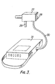
- a television camera 27 combined with a portable VTR as shown in Figure 3 has recently been widely used, the television camera 27 being connected to VTR 31 through a cable 30 to record on VTR 31 video signals of the object taken by camera 27, in which the aforesaid temporary stop (a switch 29 at the camera side gives the temporary stop order) often must be carried out.
- the above method when leaving the tape as the temporary stop for a long time, advances it little by little, whereby the head at last may reach the not-recorded portion of the tape.
- the recorded pictures of. course are not continued even when restarting the recording.
- a motor for rotating the rotary head drum of course consumes power and a current flows in other circuits, whereby the batteries are consumed to lead to a shutoff of the apparatus.
- rotary head drum 3 and other circuits are cut-off from the power source keeping the temporary stop (keeping tape 2 in Figure 1 attached to rotary head drum 3), so that the rotary drum 3 does not rotate to thereby avoid the aforesaid tape damage or head clogging.
- television camera 27 is provided with a switch 28, which is turned to "under the temporary stop", thereby cutting-off the motor driving the rotary head drum and other circuits from the power source, where the mechanical control circuit 26 should be kept energized.
- the tape is not shifted even when left for a long time and the batteries can conserve power (the camera of course is cut off) due to the fact that the mechanism unit is kept temporarily stopped and the tape need not move after the lapse of time for five minutes.
- the microcomputer has to be so programmed that the mechanical control circuit may not work even after five minutes.
- this invention aims at the protection of the magnetic tape and rotary heads in VTR when the temporary stop is carried out during the recording or reproducing.
- this invention provides a video signal recording and reproducing apparatus which is different from the conventional one which brings VTR, when left temporarily stopped, to a halt after the lapse of a given time, and protects the magnetic tape and rotary magnetic heads from being damaged, even when the magnetic tape is kept attached to the rotary magnetic drum, thereby being of a considerably large industrial value.
Landscapes
- Engineering & Computer Science (AREA)
- Computer Hardware Design (AREA)
- Management Or Editing Of Information On Record Carriers (AREA)
- Television Signal Processing For Recording (AREA)
Abstract
Description
- This invention relates to a video tape recording and reproducing apparatus using rotary magnetic heads, and more particularly to such apparatus which prevents a magnetic tape and the rotary heads from being damaged when temporarily stopped for a long time during the recording or reproducing modes and is easy to use for users of VTR.
- When video tape is temporarily stopped during the recording or reproducing modes, the stop, if for a long time, leads to the rotary magnetic heads scanning the same portion of the magnetic tape, thereby creating the problem that the magnetic layer of the tape peels off leading to tape damage or adhesion of the peeled layer to the magnetic heads. Therefore, conventionally, the temporary stop, after the lapse of a given time, is often released to put the VTR into a stop mode condition. Such a remedy, however, requires reloading of the magnetic tape on the rotary magnetic head drum for restarting the recording or reproducing, or the head shifts from the position where it has previously recorded or reproduced the tape.
- An object of the invention is to provide a video tape recording and reproducing apparatus which has improved means for the control for a temporary stop of magnetic tape during the recording or reproducing mode.
- The present invention provides a video signal recording and reproducing apparatus for a video tape recorder which loads a magnetic tape on a rotary magnetic head drum so as to record or reproduce video signals by magnetic heads, characterized in that said apparatus has a tape transportation means which temporarily stops transportation of said tape for a time T while keeping rotary magnetic heads rotating during recording or reproducing, allows said tape to advance a little after the lapse of said time T from the position of the temporary stop, and then temporarily stops said tape for said time T thereby to prevent the magnetic heads and the tape from damaging.
- Features and advantages of the invention will be more apparent from the following description of an embodiment thereof when taken in conjunction with the accompanying drawings, in which:-
- Figure 1 is a diagrammatic plan view of mechanism of a video signal recording and reproducing apparatus according to this invention using a rotary head drum;
- Figure 2 is a flow chart of the program of a microcomputer used in the apparatus shown in Figure 1; and
- Figure 3 is a perspective view of a video signal recording and reproducing apparatus of the invention, in combination with a television camera.
- In a so-called helical scan video tape recorder, a magnetic tape is wound on a rotary head drum and is recorded, while travelling, by rotary magnetic heads to produce sloping tracks in the tape, the reproduction being performed by scanning the recording tracks with the magnetic heads.
- Figure 1 is a plan view of such a mechanism in which a
mechanical chassis 1 has disposed thereon arotary head drum 3 and tape cassette 4 containingtape reels rotary head drum 3 throughloading supports 5 and 6 havingguide posts loading supports 5 and 6 move from within the cassette as shown in dotted lines to the position shown in full lines). The magnetic tape 2 is drawn off the supplyingreel 16 and is wound on the take-up reel 17 via a guide post 9, theguide posts rotary head drum 3, theguide posts head 10, a guide post 11, acapstan 13, apinch roller 12, and aguide post 25. - Next, the tape transportation means will be described on a basis of Figure 1. A driving force is transmitted from a
motor 18 to a capstan flywheel 14 (provided below chassis 1) through abelt 15, so that thecapstan 13 which is integral with theflywheel 14 rotates to move magnetic tape 2 in the direction of thearrow 19 when thepinch roller 12 presses the tape against thecapstan 13 at the finish of the tape loading operation. In addition, the magnetic tape is_ allowed to be wound on the take-upreel 17. - In some cases, the magnetic tape is temporarily stopped to be left as it is until the sequential recording starts. This happens, for example, during recording using a television camera, when selecting an object to be photographed or for a pause during recording. When this happens, the travel of the magnetic tape is temporarily brought to a halt although the VTR mode is still in the recording condition. Similarly, a temporary stop may occur during reproduction.
- It is enough for the temporary stop of the magnetic tape to stop the rotation of
motor 18 but there is a difference between the recording and the reproducing. Simply stopping rotation of themotor 18 is enough during the recording, while during reproduction, a particular design is necessary not to cause fluctuation on a picture at the boundary of the recordings prior to and after the temporary stop of the magnetic tape, which will be detailed below. In either case, the travel of magnetic tape inevitably stops and the magnetic tape 2 is scanned and rubbed at the same portion by the rotarymagnetic heads magnetic head drum 3. - The magnetic tape for VTR, even when rubbed several times on the same portion by the rotary magnetic heads, may not be damaged if rubbed for only a short time. The usual magnetic tape, however, may cause head clogging due to peeling-off of the magnetic layer and its adhesion to the magnetic heads. Hence, in order not to affect the magnetic tape or the magnetic heads a halt to the recording or reproducing modes has been often carried out hitherto after a lapse of time of, say, five minutes from the temporary stop.
- A halt in VTR means that the magnetic tape loaded on the rotary head drum is rewound into the cassette. When it is intended to restart the recording or reproducing mode from the above halt condition, a command button is pushed for recording or reproducing, but the rotary head system VTR, as well-known, must take the tape out of the cassette to be loaded on the rotary head drum. In other words, it is necessary, for the recording, reproducing and halt, to load the magnetic tape on the rotary head from the cassette: the so-called loading, and to take the loaded tape into the cassette: the so-called unloading.
- When restarting the recording or reproducing after temporary stop of the tape and the halt of VTR, the above loading and unloading operations shift the magnetic tape when reloaded, from its position with respect to the rotary head drum at the temporary stop. Recording in such conditions will create fluctuations at the boundary of recorded pictures, thereby not obtaining a reproduced picture which is the same as that at the temporary stop.
- This.invention aims at provision of a VTR free from the above defect, which is so constructed that the magnetic tape, when left as temporarily stopped, is moved forward a little, regardless of its temporary stop mode, after a lapse of time e.g. five minutes to thereby put the tape again in the temporary stop condition. Such operation is carried out by a circuit for control of the unit described above. The
mechanical control circuit 26 is altered and composed mainly of a microcomputer, so that the constant time interval T (for example about five minutes) from the temporary stop is measured by the microcomputer (a timer means) and a command of moving the tape forward a little by said tape transportation means is output by the same. - To describe this invention in full, the operation of a microcomputer (MPU) 26 will be described in conjunction with a flow chart of the program for the microcomputer which is shown in Figure 2.
- A
switch 29 by which is provided the command signal for the temporary stop (PAUSE) and the restart of the tape travel. A terminal "out" in the MPU 26 is the output for the control signal which starts or stopsmotor 18. Whenever theMPU 26 is given said control signal fromswitch 29, an output phase of one memory M1 (usually a flip-flop) in theMPU 26 is inverted. The output phase is kept unchanged unless said control signal is given. In the set state ("1") of M1, the magnetic tape travels, and in the reset state ("O") of M1, the magnetic tape does not travel, namely pause. "M1-0?" in the flow chart of Figure 2 means the judgement where M1=0 (PAUSE) or M2=0 (travel). If M1=1, "OUT" in theMPU 26 is set "1", so thatmotor 18 revolves. On the other hand, if M1=0 (PAUSE) "OUT" in the MPU 26 is reset "O" so thatmotor 18 stops. In this way, "OUT O" process in the flow chart in Figure 2 is carried out. - Next, to obtain the time interval T, "ACC" (=counter) is set the value T. Then, the ACC is decremented (substract 1), and tested if the value of ACC is O. If the value of ACC is not 0, the ACC is decremented and tested again. This operation is repeated until the value of ACC becomes O, i.e. the time interval T ends.
- After the time interval T, "OUT" of the MPU 26 is set "1" (OUT 1) so that the tape begins travelling. "OUT" is in set state during a time T o (To is counted in the same way as T1). After the time To passed, "OUT" is reset "O". The time To is a very short time. For example, To may be at least a time corresponding to one field of the television signal. After this process (OUT O), the operation returns to the starting point where the next operation is determined by the state of M1. That is, if M1=0, the tape will stop, and if M1=1, the tape will travel.
- Further, during the PAUSE state, if the start command is given, i.e. M1 becomes 1, an interruption routine (not shown) will start prior to the above routine shown in Figure 2, so that the ACC will be reset and "OUT" becomes 1 thereby to move the tape forward.
- The slightly forward movement of the tape is advantageous in that the portion of the tape rubbed for said time interval T by the rotary magnetic head is shifted slightly due to the movement of the tape, whereby the tape can be put again in the temporary stop condition. The distance ℓ for the shift is dependent on the tape speed ν cm/sec during the minimum normal reproducing or recording, divided by the field frequency ∫F:

- Next, the recording operation will be detailed. By using temporary stop facility during the recording it is desirable that the transition to the next recording will be smooth. A helical scan VTR, as is well-known, records video signals representing one field on one slope of the track, so that the scanning trace of rotary head on the tape at the temporary stop is different from that during the transportation of the tape. Hence, when the tape merely is stopped and the recording restarts, fluctuation in the picture is generated due to the transition. There are various methods to avoid the above, among which the following method is often adopted. Namely, the magnetic tape is reversely moved by ℓR (several centimeters) from the temporary stop point and then stopped. In brief, the recorded tape is moved backward only by AR and then temporarily stopped. Upon restarting the recording, the tape is normally moved, in the reproducing condition, at a length smaller than ℓR by ΔℓR from the time of the command to restart the recording, and thereafter the recording restarts. The tape in length of ℓR - ΔℓR is already recorded, so that the previously recorded portion of the tape, when kept in the reproducing condition, is not erased and the reproduction control signal can be reproduced. Hence, a servo circuit is used to phase the above signal with the synchronisation signal of video signal to be recorded sequentially, so that the reproduction control signal, upon restarting the recording, coincides in the recording phase (recording track phase) with the previously recorded signal, thus causing no fluctuation in the picture at the boundary. In addition, the previously recorded portion overlaps with the later-recorded portion only by ΔℓR, which is minimal and so scarcely affects the reproduced picture.
- Thus, even in the method for the temporary stop during the recording and for the restart of recording, unless the tape is advanced a little after five minutes from the temporary stop, the above problem of tape damage will be created. During the recording, the reproducing mode is necessary for the tape in a slight advance, otherwise, the recorded portion is doubled during the tape movement only. Alternatively, the tape may be slightly advanced by the following method. Namely, the tape, when temporarily stopped during the recording, stops in condition of being moved reversely only by ℓR as above- mentioned, and after the lapse of time for five minutes, the tape now is normally fed (in the reproduction mode) by ℓR + ΔℓR and again reversely moved to be kept in the temporary stop condition. Therefore, the tape advances normally by ΔℓR from its original position, so that the
mechanical control circuit 26 advances the tape by ℓR + ΔℓR every five minutes and carries out the reverse movement (byt R) of the tape for the temporary stop for restarting the recording, which is enough to be programmed in the microcomputer. - The VTR of the invention, in either case of recording or reproducing, can prevent the magnetic layer of the tape from peeling-off caused by the temporary stop. However, in a case of leaving the tape in the temporary stop condition for a long time while the heads are rotating, the following drawback will occur, which is eliminated, as conventional, by bringing the heads to a halt of rotation while keeping the tape loaded. For example, a
television camera 27 combined with a portable VTR as shown in Figure 3 has recently been widely used, thetelevision camera 27 being connected toVTR 31 through acable 30 to record onVTR 31 video signals of the object taken bycamera 27, in which the aforesaid temporary stop (aswitch 29 at the camera side gives the temporary stop order) often must be carried out. In this instance, the above method, when leaving the tape as the temporary stop for a long time, advances it little by little, whereby the head at last may reach the not-recorded portion of the tape. Thus, the recorded pictures of. course are not continued even when restarting the recording. Furthermore, even during the temporary stop, a motor for rotating the rotary head drum of course consumes power and a current flows in other circuits, whereby the batteries are consumed to lead to a shutoff of the apparatus. Hence, for a temporary stop lasting a long time,rotary head drum 3 and other circuits are cut-off from the power source keeping the temporary stop (keeping tape 2 in Figure 1 attached to rotary head drum 3), so that therotary drum 3 does not rotate to thereby avoid the aforesaid tape damage or head clogging. For this purpose,television camera 27 is provided with aswitch 28, which is turned to "under the temporary stop", thereby cutting-off the motor driving the rotary head drum and other circuits from the power source, where themechanical control circuit 26 should be kept energized. Hence, the tape is not shifted even when left for a long time and the batteries can conserve power (the camera of course is cut off) due to the fact that the mechanism unit is kept temporarily stopped and the tape need not move after the lapse of time for five minutes. Also, the microcomputer has to be so programmed that the mechanical control circuit may not work even after five minutes. - As seen from the above, this invention aims at the protection of the magnetic tape and rotary heads in VTR when the temporary stop is carried out during the recording or reproducing. Hence, this invention provides a video signal recording and reproducing apparatus which is different from the conventional one which brings VTR, when left temporarily stopped, to a halt after the lapse of a given time, and protects the magnetic tape and rotary magnetic heads from being damaged, even when the magnetic tape is kept attached to the rotary magnetic drum, thereby being of a considerably large industrial value.
Claims (2)
Applications Claiming Priority (2)
| Application Number | Priority Date | Filing Date | Title |
|---|---|---|---|
| JP56016166A JPS57129584A (en) | 1981-02-04 | 1981-02-04 | Magnetic recording and reproducing device of video signal |
| JP16166/81 | 1981-02-04 |
Publications (2)
| Publication Number | Publication Date |
|---|---|
| EP0058059A1 true EP0058059A1 (en) | 1982-08-18 |
| EP0058059B1 EP0058059B1 (en) | 1986-05-14 |
Family
ID=11908916
Family Applications (1)
| Application Number | Title | Priority Date | Filing Date |
|---|---|---|---|
| EP19820300569 Expired EP0058059B1 (en) | 1981-02-04 | 1982-02-04 | Video tape recording and reproducing apparatus |
Country Status (3)
| Country | Link |
|---|---|
| EP (1) | EP0058059B1 (en) |
| JP (1) | JPS57129584A (en) |
| DE (1) | DE3271090D1 (en) |
Cited By (3)
| Publication number | Priority date | Publication date | Assignee | Title |
|---|---|---|---|---|
| FR2538600A1 (en) * | 1982-09-28 | 1984-06-29 | Victor Company Of Japan | DEVICE FOR CANCELLATION OF A TEMPORARY STOP OR BREAK IN A RECORDING AND / OR REPRODUCING APPARATUS |
| EP0357035A2 (en) * | 1988-08-31 | 1990-03-07 | Sanyo Electric Co., Ltd. | Stop mode setting device in a recording/reproducing apparatus |
| WO1993021630A1 (en) * | 1992-04-10 | 1993-10-28 | Ampex Systems Corporation | Method and apparatus for minimizing tape wear in a tape recording and reproducing system |
Families Citing this family (3)
| Publication number | Priority date | Publication date | Assignee | Title |
|---|---|---|---|---|
| JPS6196542A (en) * | 1984-10-18 | 1986-05-15 | Teac Co | Magnetic tape recording device |
| JPH0750921B2 (en) * | 1985-12-18 | 1995-05-31 | ソニー株式会社 | Editing control device |
| JP2523148Y2 (en) * | 1990-05-01 | 1997-01-22 | 船井電機株式会社 | Tape recorder |
Citations (3)
| Publication number | Priority date | Publication date | Assignee | Title |
|---|---|---|---|---|
| DE2800499A1 (en) * | 1977-01-08 | 1978-07-13 | Sony Corp | VIDEO MAGNETIC TAPE |
| US4163263A (en) * | 1978-04-04 | 1979-07-31 | Basf Aktiengesellschaft | Method and apparatus for tape recording time-spaced segments of video information from a video camera |
| DE3006735A1 (en) * | 1979-02-23 | 1980-11-27 | Hitachi Ltd | VIDEO SIGNAL RECORDING AND / OR PLAYBACK DEVICE |
-
1981
- 1981-02-04 JP JP56016166A patent/JPS57129584A/en active Pending
-
1982
- 1982-02-04 EP EP19820300569 patent/EP0058059B1/en not_active Expired
- 1982-02-04 DE DE8282300569T patent/DE3271090D1/en not_active Expired
Patent Citations (4)
| Publication number | Priority date | Publication date | Assignee | Title |
|---|---|---|---|---|
| DE2800499A1 (en) * | 1977-01-08 | 1978-07-13 | Sony Corp | VIDEO MAGNETIC TAPE |
| US4161002A (en) * | 1977-01-08 | 1979-07-10 | Sony Corporation | Power conserving motor control circuit for a video tape recorder |
| US4163263A (en) * | 1978-04-04 | 1979-07-31 | Basf Aktiengesellschaft | Method and apparatus for tape recording time-spaced segments of video information from a video camera |
| DE3006735A1 (en) * | 1979-02-23 | 1980-11-27 | Hitachi Ltd | VIDEO SIGNAL RECORDING AND / OR PLAYBACK DEVICE |
Cited By (4)
| Publication number | Priority date | Publication date | Assignee | Title |
|---|---|---|---|---|
| FR2538600A1 (en) * | 1982-09-28 | 1984-06-29 | Victor Company Of Japan | DEVICE FOR CANCELLATION OF A TEMPORARY STOP OR BREAK IN A RECORDING AND / OR REPRODUCING APPARATUS |
| EP0357035A2 (en) * | 1988-08-31 | 1990-03-07 | Sanyo Electric Co., Ltd. | Stop mode setting device in a recording/reproducing apparatus |
| EP0357035A3 (en) * | 1988-08-31 | 1992-01-29 | Sanyo Electric Co., Ltd. | Stop mode setting device in a recording/reproducing apparatus |
| WO1993021630A1 (en) * | 1992-04-10 | 1993-10-28 | Ampex Systems Corporation | Method and apparatus for minimizing tape wear in a tape recording and reproducing system |
Also Published As
| Publication number | Publication date |
|---|---|
| DE3271090D1 (en) | 1986-06-19 |
| EP0058059B1 (en) | 1986-05-14 |
| JPS57129584A (en) | 1982-08-11 |
Similar Documents
| Publication | Publication Date | Title |
|---|---|---|
| US4358797A (en) | Electronic editing control apparatus for a video tape recorder | |
| KR910000649B1 (en) | Automatic program selector of a video tape recoder | |
| EP0058059B1 (en) | Video tape recording and reproducing apparatus | |
| US4482926A (en) | Method and apparatus for magnetic recording and reproducing | |
| US4786981A (en) | Edit mode controller | |
| US4408235A (en) | Recording mode locking system in a video signal magnetic recording apparatus | |
| KR970006972B1 (en) | Editing system | |
| JP2561652B2 (en) | Helical scan magnetic recording / reproducing device | |
| JPH0357546B2 (en) | ||
| JP2658033B2 (en) | Magnetic recording / reproducing device | |
| JP2505762B2 (en) | Rotating head type recording or reproducing device | |
| JP2774540B2 (en) | Tape running device | |
| JPS6019052B2 (en) | magnetic recording and reproducing device | |
| JPH0140411B2 (en) | ||
| KR0147974B1 (en) | Method for setting automatically position of video tape on recording in a video cassette recorder | |
| JP2710051B2 (en) | Magnetic recording / reproducing device | |
| JPS60140564A (en) | Magnetic recorder and reproducing device | |
| JPS6171442A (en) | Rotary head type magnetic video recording and reproducing device | |
| JPH0536154A (en) | Magnetic recording and reproducing device | |
| JPH0132582B2 (en) | ||
| JPS63113884A (en) | Magnetic recording and reproducing device | |
| JPS58111585A (en) | Video tape recorder | |
| JPH07220327A (en) | Magnetic recording and reproducing device | |
| JPH07114002B2 (en) | Video tape rack end search device | |
| JPH0822657A (en) | Magnetic recording and reproducing device |
Legal Events
| Date | Code | Title | Description |
|---|---|---|---|
| PUAI | Public reference made under article 153(3) epc to a published international application that has entered the european phase |
Free format text: ORIGINAL CODE: 0009012 |
|
| AK | Designated contracting states |
Designated state(s): DE FR GB |
|
| 17P | Request for examination filed |
Effective date: 19830216 |
|
| GRAA | (expected) grant |
Free format text: ORIGINAL CODE: 0009210 |
|
| AK | Designated contracting states |
Kind code of ref document: B1 Designated state(s): DE FR GB |
|
| REF | Corresponds to: |
Ref document number: 3271090 Country of ref document: DE Date of ref document: 19860619 |
|
| ET | Fr: translation filed | ||
| PLBE | No opposition filed within time limit |
Free format text: ORIGINAL CODE: 0009261 |
|
| STAA | Information on the status of an ep patent application or granted ep patent |
Free format text: STATUS: NO OPPOSITION FILED WITHIN TIME LIMIT |
|
| 26N | No opposition filed | ||
| PGFP | Annual fee paid to national office [announced via postgrant information from national office to epo] |
Ref country code: GB Payment date: 19970127 Year of fee payment: 16 |
|
| PGFP | Annual fee paid to national office [announced via postgrant information from national office to epo] |
Ref country code: DE Payment date: 19970207 Year of fee payment: 16 |
|
| PGFP | Annual fee paid to national office [announced via postgrant information from national office to epo] |
Ref country code: FR Payment date: 19970211 Year of fee payment: 16 |
|
| PG25 | Lapsed in a contracting state [announced via postgrant information from national office to epo] |
Ref country code: GB Free format text: LAPSE BECAUSE OF NON-PAYMENT OF DUE FEES Effective date: 19980204 |
|
| PG25 | Lapsed in a contracting state [announced via postgrant information from national office to epo] |
Ref country code: FR Free format text: THE PATENT HAS BEEN ANNULLED BY A DECISION OF A NATIONAL AUTHORITY Effective date: 19980228 |
|
| GBPC | Gb: european patent ceased through non-payment of renewal fee |
Effective date: 19980204 |
|
| PG25 | Lapsed in a contracting state [announced via postgrant information from national office to epo] |
Ref country code: DE Free format text: LAPSE BECAUSE OF NON-PAYMENT OF DUE FEES Effective date: 19981103 |
|
| REG | Reference to a national code |
Ref country code: FR Ref legal event code: ST |