EP0057853A2 - Electronic system for delivering messages - Google Patents
Electronic system for delivering messages Download PDFInfo
- Publication number
- EP0057853A2 EP0057853A2 EP82100549A EP82100549A EP0057853A2 EP 0057853 A2 EP0057853 A2 EP 0057853A2 EP 82100549 A EP82100549 A EP 82100549A EP 82100549 A EP82100549 A EP 82100549A EP 0057853 A2 EP0057853 A2 EP 0057853A2
- Authority
- EP
- European Patent Office
- Prior art keywords
- text
- memory
- pause
- digital
- speech
- Prior art date
- Legal status (The legal status is an assumption and is not a legal conclusion. Google has not performed a legal analysis and makes no representation as to the accuracy of the status listed.)
- Granted
Links
Images
Classifications
-
- G—PHYSICS
- G10—MUSICAL INSTRUMENTS; ACOUSTICS
- G10L—SPEECH ANALYSIS OR SYNTHESIS; SPEECH RECOGNITION; SPEECH OR VOICE PROCESSING; SPEECH OR AUDIO CODING OR DECODING
- G10L13/00—Speech synthesis; Text to speech systems
- G10L13/08—Text analysis or generation of parameters for speech synthesis out of text, e.g. grapheme to phoneme translation, prosody generation or stress or intonation determination
Landscapes
- Engineering & Computer Science (AREA)
- Computational Linguistics (AREA)
- Health & Medical Sciences (AREA)
- Audiology, Speech & Language Pathology (AREA)
- Human Computer Interaction (AREA)
- Physics & Mathematics (AREA)
- Acoustics & Sound (AREA)
- Multimedia (AREA)
- Analogue/Digital Conversion (AREA)
- Selective Calling Equipment (AREA)
- Transmission Systems Not Characterized By The Medium Used For Transmission (AREA)
Abstract
Description
Gegenstand der Erfindung ist ein elektronischer Textgeber zur Abgabe von Kurztexten, beispielsweise Ansagen, in Form von analogen elektrischen Signalen, bei dem die Kurztexte aus in digitaler Form in einem Festwertspeicher gespeicherten Textteilen unterschiedlicher zeitlicher Länge zusammensetzbar sind, mit einer Steuervorrichtung, an die der Festwertspeicher über einen Speicheradressenzähler angeschlossen ist und einemdem Festwertspeicher nachgeschalteten Digital-Analog-Wandler.,The invention relates to an electronic text generator for the delivery of short texts, for example announcements, in the form of analog electrical signals, in which the short texts can be composed of text parts of different lengths of time stored in digital form in a read-only memory, with a control device to which the read-only memory is transmitted a memory address counter is connected and a digital-to-analog converter connected downstream of the read-only memory.
Derartige Textgeber sind grundsätzlich bekannt. Sie sind beispielsweise zur Sprachausgabe über das Telefonnetz, beispielsweise bei der Auftragsabwicklung im Handel oder auch. bei Anrufbeantwortern eingesetzt worden. Ihre Steuerung kann von einer Datenverarbeitungsanlage, beispielsweise einem Mikrocomputer, aus erfolgen.Such text providers are generally known. They are, for example, for voice output over the telephone network, for example in order processing in the trade or also. have been used for answering machines. They can be controlled from a data processing system, for example a microcomputer.
Die Umformung der im Festwertspeicher zu speichernden Texte in digitale Sprachdaten kann dabei gemäß dem bekannten Verfahren. der Deltamodulation erfolgen. Der dem Festwertspeicher nachgeschaltete Digital-Analog-Wandler enthält dann einen. Deltademodulator.The conversion of the texts to be stored in the read-only memory into digital voice data can be carried out in accordance with the known method. delta modulation. The digital-to-analog converter downstream of the read-only memory then contains one. Delta modulator.
Ein grundsätzliches Problem der Textgeber dieser Bauart besteht darin, daß sie immer noch einen relativ hohen Bedarf an Speicherplätzen im Festwertspeicher benötigen. Hierdurch werden die Einrichtungen technisch und kostenmäßig aufwendig, was sich insbesondere dann bemerkbar macht, wenn es sich um kleinere Einrichtungen zur Abgabe ein oder mehrerer Kurztexte, wie sie beispielsweise bei einem Anrufbeantworter auftreten können, handelt.A fundamental problem of the text generators of this type is that they still require a relatively large amount of memory in the read-only memory. As a result, the facilities become technically and costly complex, which is particularly noticeable when it comes to smaller facilities for the delivery of one or more short texts, as can occur, for example, in an answering machine.
Die der Erfindung zugrunde liegende Aufgabe besteht darin, einen Textgeber der eingangs erwähnten Bauart so auszubilden, daß mit einem Minimum an Speicherplätzen Kurztexte verschiedener Art und Zusammensetzung abgegeben werden können..The object on which the invention is based is to design a text generator of the type mentioned at the outset in such a way that short texts of various types and compositions can be given with a minimum of storage spaces.
Die Erfindung geht dabei von dem Grundgedanken aus, daß für vorgegebene Sprachpausen zwischen den den Kurztext zusammensetzenden Textteilen keine Speicherplätze benötigt werden sollen und daß gleichlautende Textteile, die in mehreren Texten vorkommen, nur einmal gespeichert werden sollen.The invention is based on the basic idea that no storage spaces are required for predetermined speech pauses between the text parts composing the short text and that identical text parts that occur in several texts should only be saved once.
Die Lösung dieser Aufgabe geschieht erfindungsgemäß dadurch, daß an den Ausgang des Festwertspeichers eine Textteilende-Decodiervorrichtung zur Erkennung einer jedem Textteilende zugeordneten Markierung in den digitalen Daten angeschlossen ist, die ein Textteilende-Signal abgibt und zur Erzeugung von vorgegebenen Sprachpausen zwischen zwei Textteilen an den Ausgang des Speicheradressenzählers eine Sprachpausen-Decodiervorrichtung angeschlossen ist, zur Erkennung von Pausenanfangs- bzw. Pausenende-Markierungen, die vom Speicheradressenzähler abgegeben werden, wobei jeweils zwischen einer Pausenanfangs- und einer Pausenende-Markierung die Datenabgabe des Festwertspeichers unterbrochen ist und die Sprachpausen-Decodiervorrichtung ein Pausenende-Signal abgibt und die Ausgänge der Textteilende-Decodiervorrichtung und der Sprachpausen-Decodiervorrichtung über ein .Oder-Gatter mit der Steuervorrichtung. zur Weiterschaltung des Programmablaufes verbunden sind.This object is achieved according to the invention in that a text-part decoding device for detecting a marking in the digital data associated with each text-part end is connected to the output of the read-only memory, which emits a text-part-end signal and outputs predetermined speech pauses between two text parts at the output a speech pause decoding device is connected to the memory address counter for recognizing pause start or pause end markings which are emitted by the memory address counter, the data delivery of the read-only memory being interrupted between a pause start and a pause end mark, and the speech pause decoding device being a pause end Signal and the off the end of the text decoding device and the speech pause decoding device via an .or gate with the control device. are connected to advance the program flow.
Die Enden aller den Gesamttext zusammensetzenden 'Textteile sind demnach durch nicht hörbare Markierungen in den digitalen Daten gekennzeichnet. Diese Markierungen sind zweckmäßig bei allen Textteilen gleich und nicht an eine bestimmte Datenspeicheradresse gebunden. Dies ermöglicht eine individuelle, dem jeweiligen Textteil genau entsprechende Festlegung der Textteillängen. Die Markierungen werden von der Textteilende-Decodiervorrichtung erkannt, die ein entsprechendes Textteilende-Signal erzeugt. Die Sprachpausen werden bei der Erstellung des Programmes grundsätzlich wie Textteile behandelt. Sie werden alledings nicht in den Festwertspeicher eingespeichert, sondern es wird für die Dauer der Sprachpause ein Adressenbereich vorgegeben, in dem der Festwertspeicher nicht bestückt ist. Die Sprachpausen können durch Voreinstellung bestimmter Pausenanfangsadressen im Speicheradtessenzähler erzeugt werden, welche von der Sprachpausen-Decodiervor richtung erkannt werden, die ein Pausen- und. Pausenende-Signal abgibt. Das Textteilende-Signal und das Pausenende-Signal werden zur weiteren Steuerung des Programmablaufes verwendet.The ends of all parts of the text that compose the entire text are therefore identified by inaudible markings in the digital data. These markings are expediently the same for all text parts and are not bound to a specific data storage address. This enables an individual definition of the text part lengths that corresponds exactly to the respective text part. The markings are recognized by the end of text decoding device, which generates a corresponding end of text signal. The language breaks are treated like parts of text when the program is created. However, they are not stored in the read-only memory, but an address range is specified for the duration of the pause in which the read-only memory is not populated. The speech pauses can be generated by presetting certain pause start addresses in the memory city counter, which are recognized by the speech pause decoding device which is a pause and. End of break signal emits. The end of text signal and the end of pause signal are used to further control the program flow.
Da während der Sprachpausen dem Digital-Analog-Wandler vom Festwertspeicher her keine Daten zugeführt werden, ist es zweckmäßig, wenn gemäß Patentanspruch 2 die Sprachpausen-Decodiervorrichtung während einer vorgegebenen Sprachpause ein Steuersignal abgibt, durch das der Eingang. des Digital-Analog-Wandlers mit einer Vorrichtung zur Abgabe eines festen Eingangssignals verbunden wird, damit er während der Sprachpausen die digitalen Eingangsdaten erhält, die am Wandlerausgang den NF-Pegel "0" erzeugen.Since no data is supplied to the digital-to-analog converter from the read-only memory during the pauses in speech, it is expedient if, according to claim 2, the speech pause decoding device emits a control signal during a predetermined speech pause, by which the input. of the digital Analog converter is connected to a device for emitting a fixed input signal, so that it receives the digital input data during the pauses in speech, which generate the NF level "0" at the converter output.
Eine weitere besonders vorteilhafte Ausführungsform des erfin-dungsgemäßen Textgebers ist Gegenstand des Patentanspruchs 5. Es ist zweckmäßig, das vom Digital-Analog-Wandler abgegebene Niederfrequenz-Signal zu überwachen, um eventuelle Störungen, die beispielsweise zu Textverstümmelungen führen können, sofort zu erfassen. Durch die Kopplung dieser Überwachung des abgegebenen Niederfrequenz-Signals mit der Sprachpausen-Decodiervorrichtung wird eine besonders feinfühlige Überwachung der Niederfrequenz möglich, die dann, da sie auf die vorgegebenen Sprachpausen nicht reagiert, so empfindlich ausgelegt werden kann, daß sie schon auf geringste Unterbrechungen im Niederfrequenz-Signal im Bereich von ca. 6a Millisekunden reagiert.Another particularly advantageous embodiment of the text generator according to the invention is the subject of
Im folgenden wird anhand der Zeichnung ein Ausführungsbeispiel für den erfindungsgemäßen Textgeber näher erläutert.An exemplary embodiment of the text generator according to the invention is explained in more detail below with reference to the drawing.
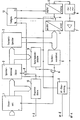
In der Zeichnung sind lediglich die für die Erfindung wesentlichen Teile des Textgebers in einem Blockschaltbild dargestellt.In the drawing, only the parts of the text generator that are essential to the invention are shown in a block diagram.
Der Programmablauf wird von ei.ner Steuervorrichtung aus gesteuert, die je nach dem Verwendungszweck des Textgebers an andere Vorrichtungen zur Überwachung und Steuerung, beispielsweise einen Mikroprozessor, angeschlossen sein kann. Alle in der Gesamtheit der abzugebenden Texte, die z.B. Ansagen sein können, vorkommenden Textteile sind nach dem bekannten Prinzip der Deltamodulation digitalisiert und in dem Festwertspeicher 3 (z.B.. ROM, EPROM) nacheinander abgelegt. Die Anfangsadressen dieser im Festwertspeicher 3 abgelegten Textteile sind in bekannter Weise im Steuerprogramm festgelegt und werden von der Steuervorrichtung 1 an den Speicheradressenzähler 2 gegeben. Die Enden aller Textteile sind durch nicht hörbare Marken in den digitalen Daten gekennzeichnet. Diese Marken sind bei allen Textteilen gleich und nicht an eine bestimmte Datenspeicheradresse gebunden. Die Ausgabe der Textteile erfolgt in der Weise, daß der Speicheradressenzähler 2 auf die Festwert-Speicheranfangsadresse eines beliebigen Textteiles. voreingestellt wird und von diesem Zählerstand ausgehend weiterschtaltet, und zwar gesteuert durch ein vom Taktgenerator 12 ausgehendes Taktsignal mit der Frequenz f6. Auf diese Weise wird der Inhalt einer Speicherzelle nach der anderen freigegeben und dem Digital-Analog-Wandler5 zugeführt. Der Festwertspeicher 3 ist in bekannter Weise in byteweiser Organisation aufgebaut, d.h. unter jeder Adresse werden 8 Bit gleichzeitig an 8 Ausgänge gegeben. Aus diesem Grund muß vor den Digital-Analog-Wandler 5, der nur serielle 1-Bit Informationen verarbeiten kann, ein Parallel-Seriell-Wandler 4 eingeschaltet werden.The program sequence is controlled by a control device which, depending on the purpose of the text generator, is sent to other monitoring and control devices, for example a microprocessor. can be connected. All parts of the text to be delivered, which can be announcements, for example, are digitized according to the known principle of delta modulation and stored in the read-only memory 3 (for example ROM, EPROM) one after the other. The start addresses of these text parts stored in the read-only memory 3 are defined in a known manner in the control program and are given by the control device 1 to the memory address counter 2. The ends of all parts of the text are marked by inaudible marks in the digital data. These marks are the same for all text parts and are not tied to a specific data storage address. The text parts are output in such a way that the memory address counter 2 points to the fixed value memory start address of any text part. is preset and incremented from this counter reading, specifically controlled by a clock signal with the frequency f6 originating from the
Die am Ende eines Textteiles auftretende Markierung wird von der Textteilende-Decodiervorrichtung 8 erkannt und über ein ODER-Gatter O wird ein entsprechendes Textteilende-Signal der Steuervorrichtung 1 und dem Speicheradressenzähler 2 zugeführt.The marking which occurs at the end of a text part is recognized by the text part
Die Erzeugung vorgegebener Sprachpausen zwischen den einzelnen Textteilen erfolgt in der Weise, daß entsprechend dem eingegebenen Programm der Speicheradressenzähler 2 auf eine Adresse innerhalb eines vorgegehenen Adressenbereiches eingestellt wird, in dem der Festwertspeicher 3 selbst nicht bestückt ist. Dabei kann so vorgegangen werden, daß dem Pausenende ein bestimmter fester Wert im Speicheradressenzähler 2 zugeordnet ist, der für alle Sprachpausen der gleiche ist. Unterschiedlich lange Pausen lassen sich dann durch die Programmierung unterschiedlicher Anfangsadressen innerhalb dieses genannten Bereiches realisieren. Auf diese Weise können auch längere Sprachpausen durch Aneinanderreihung mehrerer Pausenabschnitte erzielt werden. Die vom Speicheradressenzähler 2 abgegebenen Pausenanfangs- und Pausenende-Markierungen oder die Pausenende-Markierungen allein werden von der Sprachpausen-Decodiervorrichtung 9 erkannt. Es wird ein Sprachpausenende-Signal erzeugt, das ebenfalls über das ODER-Gatter O der Steuervorrichtung 1 und dem Speicheradressenzähler 2 zugeführt wird.Predefined speech pauses are generated between the individual text parts in such a way that, according to the program entered, the memory address counter 2 is set to an address within a previous address range in which the read-only memory 3 itself is not populated. The procedure can be such that a certain fixed value in the memory address counter 2 is assigned to the end of the pause, which is the same for all speech pauses. Pauses of different lengths can then be realized by programming different start addresses within this area. In this way, longer speech pauses can be achieved by lining up several pause sections. The pause start and pause markings output by the memory address counter 2 or the pause end markings alone are recognized by the speech pause decoding device 9. A speech pause end signal is generated, which is likewise supplied to the control device 1 and the memory address counter 2 via the OR gate O.
Zur Zusammensetzung eines bestimmten Textes aus den im Festwertspeicher 3 abgelegten Textteilen und den dazwischen auftretenden Sprachpausen werden die Textteil- Anfangsadressen und Sprachpausen-Anfangsadressen in der gewünschten Reihenfolge in das Programm der Steuerung 1 geschrieben. Beim Start des Textes und jeweils nach Erkennen eines Textteilendes durch die Textteilende-Decodiervorrichtung 8 oder eines Sprachpausenendes durch die Sprachpausen-Decodiervorrichtung 9 wird der Speicheradressenzähler 2 von der Steuerung 1 auf die nächste, im Programm folgende Textteil-Anfangsadresse voreingestellt.For the composition of a specific text from the stored in the read only memory 3 parts of text to speech pauses therebetween and the occurring Text portion A are nfangsadressen and speech pauses start addresses written in the desired order in the program of the controller. 1 At the start of the text and after each recognition of a partial text end by the partial
Der Digital-Analog-Wandler 5, der ständig vom Taktgenerator 12 mit einem Taktsignal der Frequenz f3 getaktet ist, gibt ein analoges Ausgangssignal ab, das durch ein Wiedergabefilter 6 läuft und dabei auf das für Sprachdurchsagen relevante Frequenzband begrenzt wird, wobei auch das bei der Digitalisierung unvermeidliche Quantisierungsrauschen bedämpft wird. Über einen nachgeschalteten Verstärker 7 gelangt das Niederfrequenz-Signal zum Ausgang NF-A.The digital-to-
Damit am Eingang des Digital-Analog-Wandlers 5 während der Sprachpausen, in denen vom Festwertspeicher 3 keine Daten übermittelt werden, keine undefinierten Zustände auftreten, die zu Störsignalen am Wandlerausgang führen können, gibt die Sprachpausen-Decodiervorrichtung 9 während der Sprachpausen ein Steuersignal ab, durch das mittels eines Schalters S der Eingang des Digital-Analog-Wandlers 5 während der Sprachpausen mit einem Ausgang des Taktgenerators 12 verbunden wird, von dem aus dem Digital-Analog-Wandler 5 ein getaktetes Eingangssignal der Frequenz f4 zugeführt wird. Zweckmäßig besitzt dieses Eingangssignal die Frequenz. f4 - 1/2 x f3.So that at the input of the digital-to-
Eine Programmüberwachungsvorrichtung 10 kontrolliert den Programmablauf und gibt über ein UND-Gatter U, dem gleichzeitig das Taktsignal f6 zugeführt wird, an den Speicheradressenzähler 2 die Steuersignale zum Weiterschalten. Programmenden werden über den Ausgang P-Ü angezeigt.A
Eine Vorrichtung 11 zur Überwachung des dem Ausgang NF-A zugeführten Niederfrequenz-Signals zeigt eine Störung in der Abgabe dieses Signals über den Ausgang NF-Ü an. Die Vorrichtung 11 kann als sehr empfindlich auf einen Ausfall des Niederfrequenz-Signals arbeitende Überwachungsvorrichtung ausgelegt werden, weil sie nur dann freigegeben wird, wenn "Text" programmiert ist, d.h.. während der vorgegebenen Sprachpausen wird sie durch ein von der Sprachpausen-Decodiervorrichtung 9 abgegebenes Steuersignal abgeschaltet. Auf diese Weise wird eine sehr rasch arbeitende Überwachung des abgegebenen Niederfrequenz-Signals erreicht.A device 11 for monitoring the low-frequency signal fed to the output NF-A indicates a fault in the delivery of this signal via the output NF-Ü. The device 11 can be very sensitive be designed for failure of the low frequency signal monitoring device because it is only released when "text" is programmed, ie. during the predetermined speech pauses, it is switched off by a control signal emitted by the speech pause decoding device 9. In this way, monitoring of the low-frequency signal emitted is carried out very quickly.
Claims (5)
Priority Applications (1)
| Application Number | Priority Date | Filing Date | Title |
|---|---|---|---|
| AT82100549T ATE14637T1 (en) | 1981-02-10 | 1982-01-27 | ELECTRONIC TEXT GENERATOR FOR DELIVERING SHORT TEXT. |
Applications Claiming Priority (2)
| Application Number | Priority Date | Filing Date | Title |
|---|---|---|---|
| DE3104551 | 1981-02-10 | ||
| DE3104551A DE3104551C2 (en) | 1981-02-10 | 1981-02-10 | Electronic text generator for submitting short texts |
Publications (4)
| Publication Number | Publication Date |
|---|---|
| EP0057853A2 true EP0057853A2 (en) | 1982-08-18 |
| EP0057853A3 EP0057853A3 (en) | 1982-09-01 |
| EP0057853B1 EP0057853B1 (en) | 1985-07-31 |
| EP0057853B2 EP0057853B2 (en) | 1990-01-10 |
Family
ID=6124411
Family Applications (1)
| Application Number | Title | Priority Date | Filing Date |
|---|---|---|---|
| EP82100549A Expired - Lifetime EP0057853B2 (en) | 1981-02-10 | 1982-01-27 | Electronic system for delivering messages |
Country Status (3)
| Country | Link |
|---|---|
| EP (1) | EP0057853B2 (en) |
| AT (1) | ATE14637T1 (en) |
| DE (1) | DE3104551C2 (en) |
Cited By (2)
| Publication number | Priority date | Publication date | Assignee | Title |
|---|---|---|---|---|
| FR2547094A1 (en) * | 1983-06-03 | 1984-12-07 | Silec Liaisons Elec | Method and device for broadcasting spoken messages from coded information |
| US4794639A (en) * | 1985-03-04 | 1988-12-27 | Kabushiki Kaisha Toshiba | Method and apparatus for automatically transmitting a message to a telephone terminal |
Families Citing this family (3)
| Publication number | Priority date | Publication date | Assignee | Title |
|---|---|---|---|---|
| DE3231846A1 (en) * | 1982-08-26 | 1984-03-01 | Siemens AG, 1000 Berlin und 8000 München | Telephone set with an answering machine |
| DE4135261C1 (en) * | 1991-10-25 | 1993-03-18 | International Business Machines Corp., Armonk, N.Y., Us | |
| DE10031008A1 (en) * | 2000-06-30 | 2002-01-10 | Nokia Mobile Phones Ltd | Procedure for assembling sentences for speech output |
Citations (4)
| Publication number | Priority date | Publication date | Assignee | Title |
|---|---|---|---|---|
| US3236947A (en) * | 1961-12-21 | 1966-02-22 | Ibm | Word code generator |
| DE2030987A1 (en) * | 1969-06-23 | 1971-01-07 | Instrument Systems Corp·, Hunting ton, NY (V St A ) | Electronic voice announcement system |
| FR2129756A5 (en) * | 1971-03-19 | 1972-10-27 | Western Electric Co | |
| FR2364522A1 (en) * | 1976-09-08 | 1978-04-07 | Edinen Zentar Phys | METHOD AND DEVICE FOR SPEECH SYNTHESIS |
Family Cites Families (1)
| Publication number | Priority date | Publication date | Assignee | Title |
|---|---|---|---|---|
| DE2909154A1 (en) * | 1979-03-08 | 1980-09-11 | Siemens Ag | Storage circuit for texts in information system - retains both spoken and written texts in same store |
-
1981
- 1981-02-10 DE DE3104551A patent/DE3104551C2/en not_active Expired
-
1982
- 1982-01-27 AT AT82100549T patent/ATE14637T1/en not_active IP Right Cessation
- 1982-01-27 EP EP82100549A patent/EP0057853B2/en not_active Expired - Lifetime
Patent Citations (4)
| Publication number | Priority date | Publication date | Assignee | Title |
|---|---|---|---|---|
| US3236947A (en) * | 1961-12-21 | 1966-02-22 | Ibm | Word code generator |
| DE2030987A1 (en) * | 1969-06-23 | 1971-01-07 | Instrument Systems Corp·, Hunting ton, NY (V St A ) | Electronic voice announcement system |
| FR2129756A5 (en) * | 1971-03-19 | 1972-10-27 | Western Electric Co | |
| FR2364522A1 (en) * | 1976-09-08 | 1978-04-07 | Edinen Zentar Phys | METHOD AND DEVICE FOR SPEECH SYNTHESIS |
Non-Patent Citations (3)
| Title |
|---|
| IBM TECHNICAL DISCLOSURE BULLETIN, Band 16, Nr. 11, April 1974, Seite 3744, New York, USA * |
| IBM TECHNICAL DISCLOSURE BULLETIN, Band 19, Nr. 6, November 1976, Seiten 2357,2358, New York, USA S.J. BOIES et al.: "Encoding and decoding of digital speech" * |
| IEEE TRANS. ON COMMUN., Band COM-24, Nr. 5, Mai 1976, Seiten 563-567, New York, USA * |
Cited By (2)
| Publication number | Priority date | Publication date | Assignee | Title |
|---|---|---|---|---|
| FR2547094A1 (en) * | 1983-06-03 | 1984-12-07 | Silec Liaisons Elec | Method and device for broadcasting spoken messages from coded information |
| US4794639A (en) * | 1985-03-04 | 1988-12-27 | Kabushiki Kaisha Toshiba | Method and apparatus for automatically transmitting a message to a telephone terminal |
Also Published As
| Publication number | Publication date |
|---|---|
| DE3104551C2 (en) | 1982-10-21 |
| EP0057853B1 (en) | 1985-07-31 |
| EP0057853B2 (en) | 1990-01-10 |
| DE3104551A1 (en) | 1982-08-19 |
| ATE14637T1 (en) | 1985-08-15 |
| EP0057853A3 (en) | 1982-09-01 |
Similar Documents
| Publication | Publication Date | Title |
|---|---|---|
| DE2820418A1 (en) | MESSAGE SIGNAL ENCRYPTION DEVICE | |
| DE3503306A1 (en) | DATA SIGNAL DETECTION DEVICE | |
| DE2840596A1 (en) | VOICE SYNTHESIZER | |
| DE4335305A1 (en) | Method and circuit arrangement for transmitting voice signals | |
| DE3104564C2 (en) | Automatic answering machine | |
| EP0057853B1 (en) | Electronic system for delivering messages | |
| DE3028334C2 (en) | Method for eliminating or suppressing acoustic interference signals in audio programs to be processed for the playback process | |
| DE4211945C1 (en) | ||
| DE3141254C2 (en) | Speech output device | |
| DE19643502A1 (en) | Decoding of pulse width modulated digital bus signals | |
| DE3215868C2 (en) | ||
| DE2052989A1 (en) | Procedure for triggering switching signals | |
| DE1449425B2 (en) | Device for determining errors in a magnetic tape | |
| DE3500115A1 (en) | METHOD FOR CODING A DATA BIT PATTERN, ARRANGEMENT FOR CARRYING OUT THE METHOD AND ARRANGEMENT FOR DECODING THE CHANNEL BIT FLOW OBTAINED BY THE METHOD | |
| DE3518737C2 (en) | ||
| DE2506627A1 (en) | DECODING DELTA-MODULATED SIGNALS | |
| DE3234741C2 (en) | ||
| DE2432024A1 (en) | PROCEDURE FOR OPERATING A DATA PROCESSING SYSTEM | |
| EP0054902B1 (en) | Method and apparatus for answering telephone calls automatically | |
| DE2241505C3 (en) | ||
| DE2541295A1 (en) | Test circuit for investigating PCM signals - uses audio oscillator input to encoder:decoder with binary capture circuit | |
| DE2441551A1 (en) | Multi-frequency code characters input in PCM communications network - uses linear addition of individual frequency values | |
| DE4221731C1 (en) | Method and circuit arrangement for marking voice recordings | |
| DE3229438C2 (en) | ||
| DE2104040C3 (en) | Arrangement for monitoring a PCM transmission device |
Legal Events
| Date | Code | Title | Description |
|---|---|---|---|
| PUAI | Public reference made under article 153(3) epc to a published international application that has entered the european phase |
Free format text: ORIGINAL CODE: 0009012 |
|
| PUAL | Search report despatched |
Free format text: ORIGINAL CODE: 0009013 |
|
| AK | Designated contracting states |
Designated state(s): AT BE CH GB NL SE |
|
| AK | Designated contracting states |
Designated state(s): AT BE CH GB NL SE |
|
| 17P | Request for examination filed |
Effective date: 19820929 |
|
| GRAA | (expected) grant |
Free format text: ORIGINAL CODE: 0009210 |
|
| AK | Designated contracting states |
Designated state(s): AT BE CH GB LI NL SE |
|
| REF | Corresponds to: |
Ref document number: 14637 Country of ref document: AT Date of ref document: 19850815 Kind code of ref document: T |
|
| PLBI | Opposition filed |
Free format text: ORIGINAL CODE: 0009260 |
|
| NLR1 | Nl: opposition has been filed with the epo |
Opponent name: N.V. PHILIPS' GLOEILAMPENFABRIEKEN |
|
| 26 | Opposition filed |
Opponent name: N.V. PHILIPS' GLOEILAMPENFABRIEKEN Effective date: 19860123 |
|
| PG25 | Lapsed in a contracting state [announced via postgrant information from national office to epo] |
Ref country code: SE Effective date: 19880128 |
|
| PUAH | Patent maintained in amended form |
Free format text: ORIGINAL CODE: 0009272 |
|
| STAA | Information on the status of an ep patent application or granted ep patent |
Free format text: STATUS: PATENT MAINTAINED AS AMENDED |
|
| 27A | Patent maintained in amended form |
Effective date: 19900110 |
|
| AK | Designated contracting states |
Kind code of ref document: B2 Designated state(s): AT BE CH GB NL SE |
|
| NLR2 | Nl: decision of opposition | ||
| NLR3 | Nl: receipt of modified translations in the netherlands language after an opposition procedure | ||
| PGFP | Annual fee paid to national office [announced via postgrant information from national office to epo] |
Ref country code: AT Payment date: 19931129 Year of fee payment: 13 |
|
| PGFP | Annual fee paid to national office [announced via postgrant information from national office to epo] |
Ref country code: CH Payment date: 19931229 Year of fee payment: 13 |
|
| PGFP | Annual fee paid to national office [announced via postgrant information from national office to epo] |
Ref country code: GB Payment date: 19940126 Year of fee payment: 13 |
|
| PGFP | Annual fee paid to national office [announced via postgrant information from national office to epo] |
Ref country code: NL Payment date: 19940131 Year of fee payment: 13 Ref country code: BE Payment date: 19940131 Year of fee payment: 13 |
|
| PG25 | Lapsed in a contracting state [announced via postgrant information from national office to epo] |
Ref country code: GB Effective date: 19950127 Ref country code: AT Effective date: 19950127 |
|
| EUG | Se: european patent has lapsed |
Ref document number: 82100549.3 Effective date: 19880913 |
|
| PG25 | Lapsed in a contracting state [announced via postgrant information from national office to epo] |
Ref country code: LI Effective date: 19950131 Ref country code: CH Effective date: 19950131 Ref country code: BE Effective date: 19950131 |
|
| BERE | Be: lapsed |
Owner name: NEUMANN ELEKTRONIK G.M.B.H. Effective date: 19950131 |
|
| PG25 | Lapsed in a contracting state [announced via postgrant information from national office to epo] |
Ref country code: NL Effective date: 19950801 |
|
| GBPC | Gb: european patent ceased through non-payment of renewal fee |
Effective date: 19950127 |
|
| REG | Reference to a national code |
Ref country code: CH Ref legal event code: PL |
|
| NLV4 | Nl: lapsed or anulled due to non-payment of the annual fee |
Effective date: 19950801 |
|
| APAC | Appeal dossier modified |
Free format text: ORIGINAL CODE: EPIDOS NOAPO |
|
| APAC | Appeal dossier modified |
Free format text: ORIGINAL CODE: EPIDOS NOAPO |
|
| APAH | Appeal reference modified |
Free format text: ORIGINAL CODE: EPIDOSCREFNO |