EP0055823B1 - Package for surgical sutures - Google Patents
Package for surgical sutures Download PDFInfo
- Publication number
- EP0055823B1 EP0055823B1 EP81109643A EP81109643A EP0055823B1 EP 0055823 B1 EP0055823 B1 EP 0055823B1 EP 81109643 A EP81109643 A EP 81109643A EP 81109643 A EP81109643 A EP 81109643A EP 0055823 B1 EP0055823 B1 EP 0055823B1
- Authority
- EP
- European Patent Office
- Prior art keywords
- flap
- suture
- package
- folder
- receptacle
- Prior art date
- Legal status (The legal status is an assumption and is not a legal conclusion. Google has not performed a legal analysis and makes no representation as to the accuracy of the status listed.)
- Expired
Links
Images
Classifications
-
- A—HUMAN NECESSITIES
- A61—MEDICAL OR VETERINARY SCIENCE; HYGIENE
- A61B—DIAGNOSIS; SURGERY; IDENTIFICATION
- A61B17/00—Surgical instruments, devices or methods, e.g. tourniquets
- A61B17/04—Surgical instruments, devices or methods, e.g. tourniquets for suturing wounds; Holders or packages for needles or suture materials
- A61B17/06—Needles ; Sutures; Needle-suture combinations; Holders or packages for needles or suture materials
- A61B17/06114—Packages or dispensers for needles or sutures
- A61B17/06133—Packages or dispensers for needles or sutures of parallelepipedal shape, e.g. made of rectangular or slightly oval panels
- A61B17/06138—Packages or dispensers for needles or sutures of parallelepipedal shape, e.g. made of rectangular or slightly oval panels including a retainer comprising three or more foldable panels
-
- A—HUMAN NECESSITIES
- A61—MEDICAL OR VETERINARY SCIENCE; HYGIENE
- A61B—DIAGNOSIS; SURGERY; IDENTIFICATION
- A61B17/00—Surgical instruments, devices or methods, e.g. tourniquets
- A61B17/04—Surgical instruments, devices or methods, e.g. tourniquets for suturing wounds; Holders or packages for needles or suture materials
- A61B17/06—Needles ; Sutures; Needle-suture combinations; Holders or packages for needles or suture materials
- A61B17/06114—Packages or dispensers for needles or sutures
- A61B2017/06142—Packages or dispensers for needles or sutures having needle- or suture- retaining members, e.g. holding tabs or needle parks
- A61B2017/06147—Foam blocks, e.g. slitted
Definitions
- This invention relates to a package for a surgical needle suture, and, more particularly, to a surgical suture package according to the preamble of the main claim.
- suture packages of the non-direct dispensing type are known from DE-A-29 14 480 'and DE-A-25 36 924. These prior art suture packages do not allow the dispensing of a suture without the need for manipulating the package or suture holder.
- the suture packages are designed to permit sterilizing the contents and maintaining the contents in a sterile condition until they are removed for use.
- This invention is concerned with a holding device for mounting a suture that protects the point of the needle, acts as a holding device to permit manipulation of the suture, and forms a support on which the suture is organized to avoid tangles, snags or permanent deformation yet allows rapid removal of the suture without the need for manipulating the holder.
- the problems of prior art surgical suture packages are overcome by a direct dispensing surgical suture package according to the present invention.
- the package is characterized by a foam receptacle fixed adjacent to the perimeter of at least one quadrant of the center panel and at least a first flap having a smaller perimeter than the perimeter of said panel, allowing said needle engaged in said receptacle and optionally said loop contained by said receptacle to be access- able without moving said flap relative to said panel whereby said suture is directly dispensed from said package by disengaging and pulling one of said needles, optionally after severing said loop.
- the package has a first receptacle engaging the needles and a second receptacle containing the loop.
- the package has a slit on the second receptacle for containing the loop.
- the package has a slit on the panel to contain a distal corner of the flap.
- the package has a second flap adjacent the second receptacle.
- the second flap contains an opening and the first flap has a recess to allow the loop to be accessible and to be severed without unfolding the flaps.
- the package has a third flap opposite the first flap.
- the third flap contains a recess to allow the loop to be accessible and to be severed without unfolding the flaps.
- the third flap is folded onto the second flap and partially onto the first flap.
- the package has a slit on the first flap to contain a portion of a distal edge of the third flap.
- a direct dispensing surgical suture package comprising a center panel; at least one foam receptacle having a slit, the receptacle affixed to the panel; a double-armed surgical suture with the needles engaged in and having a loop in about the midpoint of the suture contained by the receptacle slit; and at least a first flap adjacent and placed onto the panel allowing the receptacle to be accessible has also been invented.
- a direct dispensing surgical suture package comprising a center panel; at least one foam receptacle affixed to the panel; a single-armed surgical suture with the needle engaged in the receptacle; and at least a first flap adjacent and placed onto the panel allowing the receptacle to be accessible whereby the suture is dispensed from the package by disengaging and then pulling the needle, has further been invented.
- either package has a slit on the panel to contain a distal corner of the flap.
- either package has a second flap adjacent the panel and the first flap. The second flap is placed onto first flap.
- either package has a third flap opposite the first flap. The third flap is folded onto the second flap and partially onto the first flap.
- either package has a slit on the first flap to contain a portion of a distal edge of the third flap.
- either package has a folder.
- the folder contains a center panel; a recess in the folder panel to allow the needle or needles to be dispensed and with the double-armed suture, to allow the suture loop to be visible and to be severed; and at least a first flap adjacent the folder panel.
- the folder panel is placed onto the package first flap and the folder flap is placed onto the package panel.
- the folder panel is placed onto the package second flap and partially onto the first flap, or onto the third flap.
- the folder has a second flap opposite the folder first flap.
- the folder second flap is placed onto the folder first flap.
- the folder has a slit on the first flap and a coordinating tab on the folder second flap. The folder second flap is locked onto the folder first flap by the slit and coordinating tab.
- the package comprises a center panel; a foam receptacle affixed to said panel; a single-armed surgical suture with the needle engaged in the receptacle; and at least a first flap adjacent and placed onto said panel allowing said receptacle to be accessible.
- the improvement comprises a grid on the exterior package surface, whereby said suture can be dispensed from said package by disengaging and then pulling said needle, and said suture can be oriented and measured by placing it on said grid.
- inventions of the improved suture package have a second flap adjacent said panel and said first flap, said second flap placed onto said first flap; a third flap opposite said first flap, said third flap folded onto said second flap and partially onto said first flap; a slit on said first flap to contain a portion of a distal edge of said third flap; and a marking on said grid to show the distance between two parallel lines.
- Another embodiment of the improved suture package is a folder containing a center panel and a plurality of flaps, at least two adjacent flaps of said folder being folded to form a pocket, a suture package described above placed into said pocket and the remaining flaps of said folder being folded.
- the package can be dispensed from said folder, said suture can be dispensed from said package by disengaging and then pulling said needle, and said suture can be oriented and measured by placing it on said grid.
- Figure 1 describes the preferred nonabsorbable suture package.
- the package can be contained in an exterior sealed envelope, for example as described in US 4,089,410.
- Figure 1 which is incorporated by reference.
- the exterior envelope is composed of a gas pervious, bacteria- impervious spun bonded backing and transparent facing.
- a suture holder preferably composed of foldable 90 pound sterile offset paper.
- a label showing product information such as the type, size, and/or length of the suture and/or of the needles, and the manufacturer can be affixed to an exterior suture holder flap, for example flap 1c.
- Figure 2 describes the suture holder after it has been removed from the envelope and opened along score lines 3, 4 and 5 to show construction and suture configuration.
- double score lines are described, it is to be understood that single score lines are also within the scope of this invention.
- the needles 6 are held in place by insertion into a first foam receptacle 7.
- the first receptacle 7 is manufactured from a commercially available polyolefin foam, such as polyethylene or polypropylene.
- a double backed adhesive can be used to affix the foam receptacle to the suture holder.
- the suture 8 is coiled on the center panel 1 of the suture holder.
- the coil is in a helical or figure eight configuration.
- either coil configurations can be used.
- other coil configurations e.g. sinusoidal, may be used provided they allow dispensing of the suture or one-half of the suture from the holder without tangling.
- the loop is formed in about the midpoint of the suture.
- the loop is held in place by insertion into a second foam receptacle 9.
- the second receptacle 9 contains a slit 9a to contain the loop.
- the suture loop may be directed back to foam receptacle 7 and held in place by insertion into a slit within receptacle 7.
- the suture holder of this invention is direct dispensing. That is, the suture holder does not have to be unfolded during use. After removing the suture holder from the exterior envelope, the user dispenses the suture by disengaging the needles from the first receptacle and then pulling them until the suture is removed from the holder. If only one half of the suture is required, the loop is severed prior to dispensing. A term such as "CUT" and/or a symbol can be printed on the suture holder or label in a visible location proximal to the suture loop. The user dispenses about one half of the suture by disengaging one of the needles from the first receptacle and then pulling on it until about one half of the suture is removed from the holder.
- FIG 3 describes the folding sequence of the suture holder of Figure 2.
- Flap 1a is placed onto center panel 1.
- Slit 2 on center panel 1 is used to contain a distal corner of flap 1a.
- Flap 1b is then placed onto flap 1a.
- Flap 1 aids in containing the suture in the suture holder during loading and/or transporting.
- Flap 1b contains an opening to allow the loop to be visible and to be severed without unfolding the flap.
- Flap 1c is then placed onto flap 1b and partially onto flap 1a.
- Slit 16 of flap 1a is used to contain a distal edge of flap 1c.
- a recess in the edge of both flaps is necessary to allow the suture loop to be acessible and to be severed without unfolding the flaps.
- a recess in the edge of both flaps is described, it is to be understood that alternative means of allowing the suture loop to be accessible and to be severed without unfolding the flap is within the scope of this invention.
- a distal edge of flaps 1a and 1c can be adjacent to the second foam receptacle 9.
- Figure 4 describes the preferred absorbable suture package.
- the package can be contained in an interior and then in an exterior sealed envelope.
- An adequate interior and exterior envelope useful with the package of this invention is described in the prior art.
- the absorbable suture package contains a folder 10 and a suture holder 11.
- the folder 10 wraps around the suture holder to provide tear resistance to the suture holder.
- the folder 10 contains a recess to allow the needles 16 to be dispensed and to allow the suture loop to be accessible and to be severed.
- Figure 5 describes the suture holder after it has been removed from the exterior and interior envelopes, and from the folder 10, and opened along score lines 12, 13 and 14 to show construction and suture configuration.
- double score lines are described, it is to be understood that single score lines are also within the scope of this insertion.
- the needles 16 are held in place by insertion into the receptacle 15.
- the receptacle is manufactured from a commercially available polypropylene foam.
- a double backed adhesive can be used to affix the receptacle to the suture holder.
- the suture 8 is coiled on the center panel 17 of the suture holder.
- the coil is in a helical or figure eight configuration.
- either coil configuration can be used.
- other coil configurations e.g. sinusoidal, may be used provided they allow dispensing of the suture or one-half of the suture from the holder without tangling.
- a loop is formed in about the midpoint of the receptacle 15.
- the receptacle contains a slit 15a to contain the loop.
- the suture holder of this invention is direct dispensing. That is, the suture holder does not have to be unfolded nor does it have to be removed from the interior envelope and the folder during use.
- the absorbable suture holder is used by the user pulling open the exterior envelope.
- the interior envelope is then projected onto a sterile field.
- the interior envelope is then opened by a diagonal tear, exposing the receptacle 15.
- the user dispenses the suture by disengaging the needles from the receptacle and then pulling them until the suture is removed from the holder. If only one half of the suture is required, the loop is severed prior to dispensing.
- a term such as "CUT" and/or a symbol can be printed on the suture holder in a visible location proximal to the suture loop.
- the user dispenses one half of the suture by disengaging one of the needles from the receptacle and then pulling on it until about one half of the suture is removed from the holder.
- FIGs 6 and 7 describe the folding sequence of the suture holder of Figure 5 and of the folder, respectively.
- flap 17a is placed onto center panel 17.
- Slit 18 on center panel 17 is used to contain a distal corner of flap 17a.
- Flap 17b aids in containing the suture in the suture holder during loading and/or transporting.
- Flap 17c is then placed onto flap 17b and partially onto flap 17a.
- Slit 18 on flap 17a is used to contain a distal edge of flap 17c.
- flap 10a is folded such that it is contiguous with center panel 17. Flap 10b is then placed onto flap 10a. Slit 19a on flap 10a is used to contain tab 20 on flap 10b.
- Figure 8 describes a method of loading the suture holder 11 into the folder 10.
- the folder is folded as described in conjunction with Figure 7 above.
- the suture holder is then slid into the folder such that the folder recess is adjacent to the needles and the loop.
- alternative loading methods are within the scope of this invention.
- the center panel of the holder 10 can be placed onto flap 17c.
- the holder 10 can then be folded as described in conjunction with Figure 7 above.
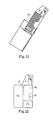
- Figure 9 describes the preferred absorbable suture package for microsurgical use.
- the package can be contained in an interior and then in an exterior sealed envelope, which are known from the prior art.
- the absorbable suture package contains a folder 10 and a suture holder 11.
- the folder 10 wraps around the suture holder to provide tear resistance to the suture holder.
- the height of the holder 11 is greater than the height of the front portion of the folder 10 to allow the needle 16 to be dispensed.
- an optional embodiment is the word "PULL" and/or an arrow affixed to the upper portion of the holder 11 to indicate the direction for dispensing it from the folder 10.
- Another optional embodiment is a dot adjacent the butt end of the needle 16 to assist the user in locating the needle in the receptacle 15.
- the preferred receptacle 15 is shown in partial view. The needle 16 is therefore shown as being visible. It is to be understood however that the needle 16 is placed into and not on the receptacle 15.
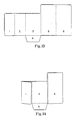
- Figure 10 describes the suture holder after it has been removed from the exterior and interior envelopes, the folder 10, and then opened along score lines 12,13 and 14 to show construction and suture configuration. It is to be understood that single or double score lines separating the respective holder panels are within the scope of this invention.
- the needle 16 is held in place by insertion into the receptacle 15.
- the receptacle is manufactured from a commercially available polypropylene foam.
- a double backed adhesive can be used to affix the receptacle 15 to the suture holder 11.
- the suture 8 is loaded onto the center panel 17. Any loading configuration may be used provided the dispensing of the suture from the holder is without tangling.
- the suture package of this invention can be direct dispensing. That is, the suture holder 11 does not have to be unfolded or removed from the interior envelope or from the folder 10 during use. Preferably, however, the suture holder 11 is removed from the folder 10.
- the absorbable suture holder 11 can be used by pulling open the exterior envelope.
- the interior envelope is then projected onto a sterile field.
- the interior envelope is then opened by a diagonal tear, exposing the needle 16 in the receptacle 15.
- the user can then dispense the suture 8 by disengaging the needle 16 from the receptacle 15 and then pulling it until the suture is removed from the package.
- the holder 11 can be removed from the folder 10. The user can then dispense the suture 8 from the holder 11 as described above.
- a grid on the exterior surface of the panel 17c can be used, for example, to orient and/or to measure the suture 8.
- a marking, for example "mm”, can be used to show the actual distance between two parallel lines of said grid.
- Figure 12 describes the folding sequence of the holder of Figure 10. Specifically, flap 17a is folded on score line 13 and placed onto center panel 17. Flap 17b is folded onto flap 17a. Flap 17b aids in containing the suture in the suture holder during loading and/or transporting. Flap 17c is then placed onto flap 17b and partially onto flap 17a. Slit 18a on flap 17a is used to contain an edge portion of flap 17c.
- Figure 13 describes the folder after it has been removed from the exterior and interior envelopes and opened. It is to be understood that single or double score lines separating the respective folder panels can be within the scope of this invention.
- Figures 14 and 15 describe the folding sequence of the suture folder of Figure 13.
- flap 1 is folded onto flap 2. Flap 1 is then folded onto the center panel 3. Flap 4 is folded onto flap 2. Flap 6 is then folded onto flap 5. Flap 6 is then folded onto flap 4 and partially onto flap 3.
- Figure 11 describes a method of loading the suture holder 11 onto the folder 10. As described above, Figure 11 also describes a method of removing the folder 10 from the holder 11.
Landscapes
- Health & Medical Sciences (AREA)
- Surgery (AREA)
- Life Sciences & Earth Sciences (AREA)
- Biomedical Technology (AREA)
- Nuclear Medicine, Radiotherapy & Molecular Imaging (AREA)
- Engineering & Computer Science (AREA)
- Dentistry (AREA)
- Heart & Thoracic Surgery (AREA)
- Medical Informatics (AREA)
- Molecular Biology (AREA)
- Animal Behavior & Ethology (AREA)
- General Health & Medical Sciences (AREA)
- Public Health (AREA)
- Veterinary Medicine (AREA)
- Surgical Instruments (AREA)
Description
- This invention relates to a package for a surgical needle suture, and, more particularly, to a surgical suture package according to the preamble of the main claim.
- This prior art is known from U.S.-A-41 20 395. The known package does not permit a direct dispensing of the suture, i.e. the package must be unfolded to allow the suture to be withdrawn.
- Other suture packages of the non-direct dispensing type are known from DE-A-29 14 480 'and DE-A-25 36 924. These prior art suture packages do not allow the dispensing of a suture without the need for manipulating the package or suture holder.
- To reduce the time of operative procedures and to permit surgeons to utilize their skills more effectively, it has become common practice to package surgical tools and appliances so that they are readily accessible to operating room personnel. In addition to using packaging techniques that permit the operating room nurse and the surgeon to manipulate the various surgical devices, the devices are packaged in a sterile environment, so that they are immediately available for use.
- In conformance, it has become common practice to package and store surgical needles and sutures in sterile packages. These packages are designed to permit sterilizing the contents, and storing surgical needles and sutures in sterile packages.
- The suture packages are designed to permit sterilizing the contents and maintaining the contents in a sterile condition until they are removed for use.
- This invention is concerned with a holding device for mounting a suture that protects the point of the needle, acts as a holding device to permit manipulation of the suture, and forms a support on which the suture is organized to avoid tangles, snags or permanent deformation yet allows rapid removal of the suture without the need for manipulating the holder.
- The problems of prior art surgical suture packages are overcome by a direct dispensing surgical suture package according to the present invention. The package is characterized by a foam receptacle fixed adjacent to the perimeter of at least one quadrant of the center panel and at least a first flap having a smaller perimeter than the perimeter of said panel, allowing said needle engaged in said receptacle and optionally said loop contained by said receptacle to be access- able without moving said flap relative to said panel whereby said suture is directly dispensed from said package by disengaging and pulling one of said needles, optionally after severing said loop.
- In one embodiment, the package has a first receptacle engaging the needles and a second receptacle containing the loop. In another embodiment, the package has a slit on the second receptacle for containing the loop. In yet another embodiment, the package has a slit on the panel to contain a distal corner of the flap.
- In still another embodiment, the package has a second flap adjacent the second receptacle. The second flap contains an opening and the first flap has a recess to allow the loop to be accessible and to be severed without unfolding the flaps. In yet another embodiment, the package has a third flap opposite the first flap. The third flap contains a recess to allow the loop to be accessible and to be severed without unfolding the flaps. The third flap is folded onto the second flap and partially onto the first flap. In still yet another embodiment, the package has a slit on the first flap to contain a portion of a distal edge of the third flap.
- A direct dispensing surgical suture package comprising a center panel; at least one foam receptacle having a slit, the receptacle affixed to the panel; a double-armed surgical suture with the needles engaged in and having a loop in about the midpoint of the suture contained by the receptacle slit; and at least a first flap adjacent and placed onto the panel allowing the receptacle to be accessible has also been invented. A direct dispensing surgical suture package comprising a center panel; at least one foam receptacle affixed to the panel; a single-armed surgical suture with the needle engaged in the receptacle; and at least a first flap adjacent and placed onto the panel allowing the receptacle to be accessible whereby the suture is dispensed from the package by disengaging and then pulling the needle, has further been invented. In one embodiment, either package has a slit on the panel to contain a distal corner of the flap. In another embodiment, either package has a second flap adjacent the panel and the first flap. The second flap is placed onto first flap. Still in another embodiment, either package has a third flap opposite the first flap. The third flap is folded onto the second flap and partially onto the first flap. In yet another embodiment, either package has a slit on the first flap to contain a portion of a distal edge of the third flap. In still another embodiment, either package has a folder. The folder contains a center panel; a recess in the folder panel to allow the needle or needles to be dispensed and with the double-armed suture, to allow the suture loop to be visible and to be severed; and at least a first flap adjacent the folder panel. The folder panel is placed onto the package first flap and the folder flap is placed onto the package panel. Alternatively, the folder panel is placed onto the package second flap and partially onto the first flap, or onto the third flap.
- In yet another embodiment, the folder has a second flap opposite the folder first flap. The folder second flap is placed onto the folder first flap. In still yet another embodiment, the folder has a slit on the first flap and a coordinating tab on the folder second flap. The folder second flap is locked onto the folder first flap by the slit and coordinating tab.
- An improved direct dispensing surgical suture package, particularly for microsurgical use, has also been invented. The package comprises a center panel; a foam receptacle affixed to said panel; a single-armed surgical suture with the needle engaged in the receptacle; and at least a first flap adjacent and placed onto said panel allowing said receptacle to be accessible. The improvement comprises a grid on the exterior package surface, whereby said suture can be dispensed from said package by disengaging and then pulling said needle, and said suture can be oriented and measured by placing it on said grid.
- Other embodiments of the improved suture package have a second flap adjacent said panel and said first flap, said second flap placed onto said first flap; a third flap opposite said first flap, said third flap folded onto said second flap and partially onto said first flap; a slit on said first flap to contain a portion of a distal edge of said third flap; and a marking on said grid to show the distance between two parallel lines.
- Another embodiment of the improved suture package is a folder containing a center panel and a plurality of flaps, at least two adjacent flaps of said folder being folded to form a pocket, a suture package described above placed into said pocket and the remaining flaps of said folder being folded. The package can be dispensed from said folder, said suture can be dispensed from said package by disengaging and then pulling said needle, and said suture can be oriented and measured by placing it on said grid.
-
- Figures 1 and 4 are perspective views and Figure 9 is a front view of alternative suture packages of this invention;
- Figures 2, 5 and 10 are front views of the Figures 1, 4 and 9, respectively;
- Figures 3 and 6 are perspective views and Figure 12 is a front view showing the folding sequence of the suture packages of Figures 2, 5 and 10, respectively;
- Figure 7 is a perspective view, and Figures 13 to 15 are front views showing the folding sequence of folders useful with the suture packages of Figures 4 and 9, respectively;
- Figure 8 is a perspective view showing the suture package of Figure 4 being loaded into the folder of Figure 7; and
- Figure 11 is a perspective view showing the suture package of Figure 9 being removed from the folder of Figures 13 to 15.
- The essence of this invention, described in conjunction with the attached drawings, comprises a folded paper holder for a double or single-armed ophthalmic suture. The holders for absorbable and nonabsorbable sutures are slightly different and are described separately below.
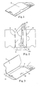
- Figure 1 describes the preferred nonabsorbable suture package. The package can be contained in an exterior sealed envelope, for example as described in US 4,089,410. Figure 1 which is incorporated by reference. Preferably, the exterior envelope is composed of a gas pervious, bacteria- impervious spun bonded backing and transparent facing. Within this invelope is a suture holder, preferably composed of foldable 90 pound sterile offset paper. A label showing product information such as the type, size, and/or length of the suture and/or of the needles, and the manufacturer can be affixed to an exterior suture holder flap, for example flap 1c.
- Figure 2 describes the suture holder after it has been removed from the envelope and opened along
score lines needles 6 are held in place by insertion into afirst foam receptacle 7. Preferably, thefirst receptacle 7 is manufactured from a commercially available polyolefin foam, such as polyethylene or polypropylene. A double backed adhesive can be used to affix the foam receptacle to the suture holder. - The
suture 8 is coiled on thecenter panel 1 of the suture holder. Preferably, the coil is in a helical or figure eight configuration. Generally, either coil configurations can be used. Also, other coil configurations, e.g. sinusoidal, may be used provided they allow dispensing of the suture or one-half of the suture from the holder without tangling. After coiling, the loop is formed in about the midpoint of the suture. The loop is held in place by insertion into a second foam receptacle 9. The second receptacle 9 contains aslit 9a to contain the loop. Optionally, the suture loop may be directed back tofoam receptacle 7 and held in place by insertion into a slit withinreceptacle 7. - The suture holder of this invention is direct dispensing. That is, the suture holder does not have to be unfolded during use. After removing the suture holder from the exterior envelope, the user dispenses the suture by disengaging the needles from the first receptacle and then pulling them until the suture is removed from the holder. If only one half of the suture is required, the loop is severed prior to dispensing. A term such as "CUT" and/or a symbol can be printed on the suture holder or label in a visible location proximal to the suture loop. The user dispenses about one half of the suture by disengaging one of the needles from the first receptacle and then pulling on it until about one half of the suture is removed from the holder.
- Figure 3 describes the folding sequence of the suture holder of Figure 2. Flap 1a is placed onto
center panel 1.Slit 2 oncenter panel 1 is used to contain a distal corner of flap 1a. Flap 1b is then placed onto flap 1a.Flap 1 aids in containing the suture in the suture holder during loading and/or transporting. Flap 1b contains an opening to allow the loop to be visible and to be severed without unfolding the flap. Flap 1c is then placed onto flap 1b and partially onto flap 1a.Slit 16 of flap 1a is used to contain a distal edge of flap 1c. - Referring to Figure 3, when a distal edge of flaps 1a and 1c are adjacent to the score line(s) 5, a recess in the edge of both flaps is necessary to allow the suture loop to be acessible and to be severed without unfolding the flaps. Although a recess in the edge of both flaps is described, it is to be understood that alternative means of allowing the suture loop to be accessible and to be severed without unfolding the flap is within the scope of this invention. For example, a distal edge of flaps 1a and 1c can be adjacent to the second foam receptacle 9.
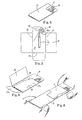
- Figure 4 describes the preferred absorbable suture package. The package can be contained in an interior and then in an exterior sealed envelope. An adequate interior and exterior envelope useful with the package of this invention is described in the prior art.
- Referred to Figure 4, the absorbable suture package contains a
folder 10 and a suture holder 11. Thefolder 10 wraps around the suture holder to provide tear resistance to the suture holder. Thefolder 10 contains a recess to allow theneedles 16 to be dispensed and to allow the suture loop to be accessible and to be severed. - Figure 5 describes the suture holder after it has been removed from the exterior and interior envelopes, and from the
folder 10, and opened alongscore lines needles 16 are held in place by insertion into thereceptacle 15. Preferably, the receptacle is manufactured from a commercially available polypropylene foam. A double backed adhesive can be used to affix the receptacle to the suture holder. - The
suture 8 is coiled on thecenter panel 17 of the suture holder. Preferably, the coil is in a helical or figure eight configuration. Generally, either coil configuration can be used. Also, other coil configurations, e.g. sinusoidal, may be used provided they allow dispensing of the suture or one-half of the suture from the holder without tangling. After coiling, a loop is formed in about the midpoint of thereceptacle 15. The receptacle contains a slit 15a to contain the loop. - The suture holder of this invention is direct dispensing. That is, the suture holder does not have to be unfolded nor does it have to be removed from the interior envelope and the folder during use. The absorbable suture holder is used by the user pulling open the exterior envelope. The interior envelope is then projected onto a sterile field. The interior envelope is then opened by a diagonal tear, exposing the
receptacle 15. The user dispenses the suture by disengaging the needles from the receptacle and then pulling them until the suture is removed from the holder. If only one half of the suture is required, the loop is severed prior to dispensing. A term such as "CUT" and/or a symbol can be printed on the suture holder in a visible location proximal to the suture loop. The user dispenses one half of the suture by disengaging one of the needles from the receptacle and then pulling on it until about one half of the suture is removed from the holder. - Figures 6 and 7 describe the folding sequence of the suture holder of Figure 5 and of the folder, respectively. Referring to Figure 6, flap 17a is placed onto
center panel 17.Slit 18 oncenter panel 17 is used to contain a distal corner of flap 17a.Flap 17b aids in containing the suture in the suture holder during loading and/or transporting.Flap 17c is then placed ontoflap 17b and partially onto flap 17a.Slit 18 on flap 17a is used to contain a distal edge offlap 17c. - Referring to Figure 7,
flap 10a is folded such that it is contiguous withcenter panel 17. Flap 10b is then placed ontoflap 10a.Slit 19a onflap 10a is used to containtab 20 on flap 10b. - Figure 8 describes a method of loading the suture holder 11 into the
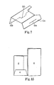
folder 10. The folder is folded as described in conjunction with Figure 7 above. The suture holder is then slid into the folder such that the folder recess is adjacent to the needles and the loop. It is to be understood that alternative loading methods are within the scope of this invention. For example, the center panel of theholder 10 can be placed ontoflap 17c. Theholder 10 can then be folded as described in conjunction with Figure 7 above. - Figure 9 describes the preferred absorbable suture package for microsurgical use. The package can be contained in an interior and then in an exterior sealed envelope, which are known from the prior art.
- Referring to Figure 9,'the absorbable suture package contains a
folder 10 and a suture holder 11. Thefolder 10 wraps around the suture holder to provide tear resistance to the suture holder. The height of the holder 11 is greater than the height of the front portion of thefolder 10 to allow theneedle 16 to be dispensed. - Referring to Figures 9 to 12, an optional embodiment is the word "PULL" and/or an arrow affixed to the upper portion of the holder 11 to indicate the direction for dispensing it from the
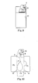
folder 10. Another optional embodiment is a dot adjacent the butt end of theneedle 16 to assist the user in locating the needle in thereceptacle 15. Finally, thepreferred receptacle 15 is shown in partial view. Theneedle 16 is therefore shown as being visible. It is to be understood however that theneedle 16 is placed into and not on thereceptacle 15. - Figure 10 describes the suture holder after it has been removed from the exterior and interior envelopes, the
folder 10, and then opened alongscore lines needle 16 is held in place by insertion into thereceptacle 15. Preferably, the receptacle is manufactured from a commercially available polypropylene foam. A double backed adhesive can be used to affix thereceptacle 15 to the suture holder 11. - The
suture 8 is loaded onto thecenter panel 17. Any loading configuration may be used provided the dispensing of the suture from the holder is without tangling. - The suture package of this invention can be direct dispensing. That is, the suture holder 11 does not have to be unfolded or removed from the interior envelope or from the
folder 10 during use. Preferably, however, the suture holder 11 is removed from thefolder 10. - The absorbable suture holder 11 can be used by pulling open the exterior envelope. The interior envelope is then projected onto a sterile field. The interior envelope is then opened by a diagonal tear, exposing the
needle 16 in thereceptacle 15. The user can then dispense thesuture 8 by disengaging theneedle 16 from thereceptacle 15 and then pulling it until the suture is removed from the package. - Alternatively, referring to Figure 11, the holder 11 can be removed from the
folder 10. The user can then dispense thesuture 8 from the holder 11 as described above. A grid on the exterior surface of thepanel 17c can be used, for example, to orient and/or to measure thesuture 8. A marking, for example "mm", can be used to show the actual distance between two parallel lines of said grid. - Figure 12 describes the folding sequence of the holder of Figure 10. Specifically, flap 17a is folded on
score line 13 and placed ontocenter panel 17.Flap 17b is folded onto flap 17a.Flap 17b aids in containing the suture in the suture holder during loading and/or transporting.Flap 17c is then placed ontoflap 17b and partially onto flap 17a. Slit 18a on flap 17a is used to contain an edge portion offlap 17c. - Figure 13 describes the folder after it has been removed from the exterior and interior envelopes and opened. It is to be understood that single or double score lines separating the respective folder panels can be within the scope of this invention. Figures 14 and 15 describe the folding sequence of the suture folder of Figure 13.
- Referring to Figures 14 and 15,
flap 1 is folded ontoflap 2.Flap 1 is then folded onto thecenter panel 3.Flap 4 is folded ontoflap 2.Flap 6 is then folded ontoflap 5.Flap 6 is then folded ontoflap 4 and partially ontoflap 3. - Figure 11 describes a method of loading the suture holder 11 onto the
folder 10. As described above, Figure 11 also describes a method of removing thefolder 10 from the holder 11. - An alternative method of loading the holder 11 into the
folder 10 as described in conjunction with Figures 14 and 15. The suture holder 11 can be placed in the pocket of the partially formedfolder 10 betweenflaps center panel 17 can be placed onto flap I of thefolder 10. Thefolder 10 can then be completely assembled as described in Figures 14 and 15.
Claims (5)
Applications Claiming Priority (2)
| Application Number | Priority Date | Filing Date | Title |
|---|---|---|---|
| US21559880A | 1980-12-12 | 1980-12-12 | |
| US215598 | 1980-12-12 |
Publications (2)
| Publication Number | Publication Date |
|---|---|
| EP0055823A1 EP0055823A1 (en) | 1982-07-14 |
| EP0055823B1 true EP0055823B1 (en) | 1985-09-18 |
Family
ID=22803623
Family Applications (1)
| Application Number | Title | Priority Date | Filing Date |
|---|---|---|---|
| EP81109643A Expired EP0055823B1 (en) | 1980-12-12 | 1981-11-12 | Package for surgical sutures |
Country Status (13)
| Country | Link |
|---|---|
| EP (1) | EP0055823B1 (en) |
| JP (2) | JPS57119733A (en) |
| KR (1) | KR880001044B1 (en) |
| AU (1) | AU546470B2 (en) |
| BR (1) | BR8108078A (en) |
| CA (1) | CA1201094A (en) |
| DE (1) | DE3172369D1 (en) |
| DK (1) | DK550481A (en) |
| ES (1) | ES261988Y (en) |
| FI (1) | FI813995L (en) |
| MX (1) | MX155284A (en) |
| NO (1) | NO814241L (en) |
| ZA (1) | ZA818639B (en) |
Families Citing this family (12)
| Publication number | Priority date | Publication date | Assignee | Title |
|---|---|---|---|---|
| JPS6083648A (en) * | 1983-10-13 | 1985-05-11 | エチコン・インコーポレーテツド | Holder for aseptic surgical product |
| JPS61176333A (en) * | 1985-01-30 | 1986-08-08 | 株式会社日本メデイカル・サプライ | Packing of suturing yarn |
| JPS63288146A (en) * | 1987-05-20 | 1988-11-25 | Nippon Medical Supply Corp | Base paper for packing suture |
| JPH0644406Y2 (en) * | 1987-12-25 | 1994-11-16 | ノボシビルスキ ナウチノ―イススレドバテルスキ インスティテュトパトロギイ クロボオブラシェニア | Sewing thread retainer |
| FR2639215A1 (en) * | 1988-11-22 | 1990-05-25 | Raynaud Guy | Presentation element for crimped surgical thread |
| US5425445A (en) * | 1989-08-01 | 1995-06-20 | United States Surgical Corporation | Retainer for a combined surgical suture-needle device |
| US5165217A (en) * | 1989-09-12 | 1992-11-24 | Ethicon, Inc. | One piece channel suture packages |
| US5236083A (en) * | 1989-09-12 | 1993-08-17 | Ethicon, Inc. | One piece channel suture packages |
| CA2055798C (en) * | 1991-01-03 | 2002-07-16 | Henry A. Holzwarth | Package for surgical sutures |
| US5101968A (en) * | 1991-05-07 | 1992-04-07 | Lukens Medical Corporation | Retainers for needled surgical sutures |
| DE4335659C1 (en) * | 1993-10-15 | 1995-05-04 | Ethicon Gmbh | Packaging with surgical sutures |
| US9943306B2 (en) | 2009-04-14 | 2018-04-17 | Covidien Lp | Knotless endostitch suture retainer |
Citations (2)
| Publication number | Priority date | Publication date | Assignee | Title |
|---|---|---|---|---|
| DE2536924A1 (en) * | 1974-08-28 | 1976-03-11 | Ethicon Inc | FASTENING AND DISPENSING DEVICE FOR NEEDLEED SUTURE MATERIAL, IN PARTICULAR MICRO-SUTURE MATERIAL FOR SURGICAL PURPOSES |
| DE2914480A1 (en) * | 1979-04-06 | 1980-10-16 | Berliner Catgutfabrik Gmbh | Sterile surgical thread pack - has two detachable flanges forming reel with clamp for thread end |
Family Cites Families (2)
| Publication number | Priority date | Publication date | Assignee | Title |
|---|---|---|---|---|
| US4120395A (en) * | 1977-09-02 | 1978-10-17 | Ethicon, Inc. | Package for double-armed sutures |
| US4089410A (en) * | 1977-09-06 | 1978-05-16 | American Cyanamid Company | Package for fine sutures, non-needled, single or double armed |
-
1981
- 1981-11-12 DE DE8181109643T patent/DE3172369D1/en not_active Expired
- 1981-11-12 EP EP81109643A patent/EP0055823B1/en not_active Expired
- 1981-11-13 CA CA000390034A patent/CA1201094A/en not_active Expired
- 1981-12-08 JP JP56196411A patent/JPS57119733A/en active Pending
- 1981-12-10 KR KR1019810004843A patent/KR880001044B1/en active
- 1981-12-11 AU AU78462/81A patent/AU546470B2/en not_active Expired
- 1981-12-11 ES ES1981261988U patent/ES261988Y/en not_active Expired
- 1981-12-11 FI FI813995A patent/FI813995L/en not_active Application Discontinuation
- 1981-12-11 MX MX190592A patent/MX155284A/en unknown
- 1981-12-11 DK DK550481A patent/DK550481A/en not_active Application Discontinuation
- 1981-12-11 BR BR8108078A patent/BR8108078A/en unknown
- 1981-12-11 ZA ZA818639A patent/ZA818639B/en unknown
- 1981-12-11 NO NO814241A patent/NO814241L/en unknown
-
1991
- 1991-06-17 JP JP1991053602U patent/JP2500297Y2/en not_active Expired - Lifetime
Patent Citations (2)
| Publication number | Priority date | Publication date | Assignee | Title |
|---|---|---|---|---|
| DE2536924A1 (en) * | 1974-08-28 | 1976-03-11 | Ethicon Inc | FASTENING AND DISPENSING DEVICE FOR NEEDLEED SUTURE MATERIAL, IN PARTICULAR MICRO-SUTURE MATERIAL FOR SURGICAL PURPOSES |
| DE2914480A1 (en) * | 1979-04-06 | 1980-10-16 | Berliner Catgutfabrik Gmbh | Sterile surgical thread pack - has two detachable flanges forming reel with clamp for thread end |
Also Published As
| Publication number | Publication date |
|---|---|
| JP2500297Y2 (en) | 1996-06-05 |
| ES261988Y (en) | 1983-04-01 |
| AU7846281A (en) | 1982-06-17 |
| DK550481A (en) | 1982-06-13 |
| EP0055823A1 (en) | 1982-07-14 |
| AU546470B2 (en) | 1985-09-05 |
| MX155284A (en) | 1988-02-12 |
| ES261988U (en) | 1982-11-01 |
| ZA818639B (en) | 1982-10-27 |
| JPH0488916U (en) | 1992-08-03 |
| DE3172369D1 (en) | 1985-10-24 |
| KR880001044B1 (en) | 1988-06-18 |
| JPS57119733A (en) | 1982-07-26 |
| CA1201094A (en) | 1986-02-25 |
| FI813995L (en) | 1982-06-13 |
| BR8108078A (en) | 1982-09-21 |
| NO814241L (en) | 1982-06-14 |
Similar Documents
| Publication | Publication Date | Title |
|---|---|---|
| US4391365A (en) | Single dispensing multiple suture package | |
| US4412613A (en) | Microsurgical foam needle control package | |
| US4708241A (en) | Suture package | |
| US4183431A (en) | Access suture package | |
| US4089410A (en) | Package for fine sutures, non-needled, single or double armed | |
| US4574948A (en) | Linear fold armed suture | |
| EP0060080B1 (en) | Pop-up armed suture | |
| EP0168161A1 (en) | A folder for surgical sutures | |
| CA2014624C (en) | Self-contained surgical suture package | |
| GB1598733A (en) | Direct dispensing label for packing of surgical sutures and suture package containing same | |
| EP0055823B1 (en) | Package for surgical sutures | |
| US4069912A (en) | Suture package | |
| US4168000A (en) | Suture package | |
| EP1346693B1 (en) | Two-tiered multistrand suture folder | |
| EP0591858A2 (en) | Suture display rack and procedure kit | |
| US4142628A (en) | Direct dispensing suture package for a multiple of sterile surgical sutures with or without needles attached | |
| US5348146A (en) | Suture package | |
| US4105115A (en) | Suture and needle holder | |
| US4168001A (en) | Suture and needle holder | |
| US6409016B1 (en) | Holder and dispenser for spools, tube-shaped devices, and cylindrical devices with recessed ends | |
| JPS6077746A (en) | Folding holder for suturing yarn wound in snail like form |
Legal Events
| Date | Code | Title | Description |
|---|---|---|---|
| PUAI | Public reference made under article 153(3) epc to a published international application that has entered the european phase |
Free format text: ORIGINAL CODE: 0009012 |
|
| AK | Designated contracting states |
Designated state(s): BE CH DE FR GB IT NL SE |
|
| 17P | Request for examination filed |
Effective date: 19821021 |
|
| ITF | It: translation for a ep patent filed |
Owner name: MODIANO & ASSOCIATI S.R.L. |
|
| GRAA | (expected) grant |
Free format text: ORIGINAL CODE: 0009210 |
|
| AK | Designated contracting states |
Designated state(s): BE CH DE FR GB IT LI NL SE |
|
| REF | Corresponds to: |
Ref document number: 3172369 Country of ref document: DE Date of ref document: 19851024 |
|
| ET | Fr: translation filed | ||
| PLBE | No opposition filed within time limit |
Free format text: ORIGINAL CODE: 0009261 |
|
| STAA | Information on the status of an ep patent application or granted ep patent |
Free format text: STATUS: NO OPPOSITION FILED WITHIN TIME LIMIT |
|
| 26N | No opposition filed | ||
| PGFP | Annual fee paid to national office [announced via postgrant information from national office to epo] |
Ref country code: NL Payment date: 19901130 Year of fee payment: 10 |
|
| PG25 | Lapsed in a contracting state [announced via postgrant information from national office to epo] |
Ref country code: NL Effective date: 19920601 |
|
| NLV4 | Nl: lapsed or anulled due to non-payment of the annual fee | ||
| ITTA | It: last paid annual fee | ||
| EAL | Se: european patent in force in sweden |
Ref document number: 81109643.7 |
|
| PGFP | Annual fee paid to national office [announced via postgrant information from national office to epo] |
Ref country code: SE Payment date: 19971106 Year of fee payment: 17 |
|
| PGFP | Annual fee paid to national office [announced via postgrant information from national office to epo] |
Ref country code: BE Payment date: 19971211 Year of fee payment: 17 |
|
| PGFP | Annual fee paid to national office [announced via postgrant information from national office to epo] |
Ref country code: CH Payment date: 19980108 Year of fee payment: 17 |
|
| PG25 | Lapsed in a contracting state [announced via postgrant information from national office to epo] |
Ref country code: SE Free format text: LAPSE BECAUSE OF NON-PAYMENT OF DUE FEES Effective date: 19981113 |
|
| PG25 | Lapsed in a contracting state [announced via postgrant information from national office to epo] |
Ref country code: LI Free format text: LAPSE BECAUSE OF NON-PAYMENT OF DUE FEES Effective date: 19981130 Ref country code: CH Free format text: LAPSE BECAUSE OF NON-PAYMENT OF DUE FEES Effective date: 19981130 Ref country code: BE Free format text: LAPSE BECAUSE OF NON-PAYMENT OF DUE FEES Effective date: 19981130 |
|
| BERE | Be: lapsed |
Owner name: AMERICAN CYANAMID CY Effective date: 19981130 |
|
| REG | Reference to a national code |
Ref country code: CH Ref legal event code: PL |
|
| EUG | Se: european patent has lapsed |
Ref document number: 81109643.7 |
|
| PGFP | Annual fee paid to national office [announced via postgrant information from national office to epo] |
Ref country code: FR Payment date: 20001018 Year of fee payment: 20 |
|
| PGFP | Annual fee paid to national office [announced via postgrant information from national office to epo] |
Ref country code: DE Payment date: 20001019 Year of fee payment: 20 |
|
| PGFP | Annual fee paid to national office [announced via postgrant information from national office to epo] |
Ref country code: GB Payment date: 20001020 Year of fee payment: 20 |
|
| PG25 | Lapsed in a contracting state [announced via postgrant information from national office to epo] |
Ref country code: GB Free format text: LAPSE BECAUSE OF EXPIRATION OF PROTECTION Effective date: 20011111 |
|
| REG | Reference to a national code |
Ref country code: GB Ref legal event code: PE20 Effective date: 20011111 |
|
| REG | Reference to a national code |
Ref country code: FR Ref legal event code: TP |