EP0053680B1 - Device for objective and subjective refraction measurement - Google Patents
Device for objective and subjective refraction measurement Download PDFInfo
- Publication number
- EP0053680B1 EP0053680B1 EP81108496A EP81108496A EP0053680B1 EP 0053680 B1 EP0053680 B1 EP 0053680B1 EP 81108496 A EP81108496 A EP 81108496A EP 81108496 A EP81108496 A EP 81108496A EP 0053680 B1 EP0053680 B1 EP 0053680B1
- Authority
- EP
- European Patent Office
- Prior art keywords
- eye
- test
- ray path
- mark
- mirror
- Prior art date
- Legal status (The legal status is an assumption and is not a legal conclusion. Google has not performed a legal analysis and makes no representation as to the accuracy of the status listed.)
- Expired
Links
Images
Classifications
-
- A—HUMAN NECESSITIES
- A61—MEDICAL OR VETERINARY SCIENCE; HYGIENE
- A61B—DIAGNOSIS; SURGERY; IDENTIFICATION
- A61B3/00—Apparatus for testing the eyes; Instruments for examining the eyes
- A61B3/02—Subjective types, i.e. testing apparatus requiring the active assistance of the patient
- A61B3/028—Subjective types, i.e. testing apparatus requiring the active assistance of the patient for testing visual acuity; for determination of refraction, e.g. phoropters
- A61B3/036—Subjective types, i.e. testing apparatus requiring the active assistance of the patient for testing visual acuity; for determination of refraction, e.g. phoropters for testing astigmatism
-
- A—HUMAN NECESSITIES
- A61—MEDICAL OR VETERINARY SCIENCE; HYGIENE
- A61B—DIAGNOSIS; SURGERY; IDENTIFICATION
- A61B3/00—Apparatus for testing the eyes; Instruments for examining the eyes
- A61B3/02—Subjective types, i.e. testing apparatus requiring the active assistance of the patient
- A61B3/028—Subjective types, i.e. testing apparatus requiring the active assistance of the patient for testing visual acuity; for determination of refraction, e.g. phoropters
-
- A—HUMAN NECESSITIES
- A61—MEDICAL OR VETERINARY SCIENCE; HYGIENE
- A61B—DIAGNOSIS; SURGERY; IDENTIFICATION
- A61B3/00—Apparatus for testing the eyes; Instruments for examining the eyes
- A61B3/10—Objective types, i.e. instruments for examining the eyes independent of the patients' perceptions or reactions
- A61B3/103—Objective types, i.e. instruments for examining the eyes independent of the patients' perceptions or reactions for determining refraction, e.g. refractometers, skiascopes
Definitions
- the present invention relates to a device for subjective and objective refraction determination.
- a device for subjective and simultaneous objective refraction determination in which two test marks are simultaneously projected onto different screens in different spectral ranges and the subject observes this screen through a phoropter.
- the light reflected from the retina of the eye is reflected out of the illuminating beam path via a partially transparent mirror and imaged into an image plane by means of optics.
- the observer changes the phoropter setting until the retinal image appears sharp in the image plane.
- the patient can monitor the improvement in vision by observing one of the test marks and can thus participate in the optimal setting himself.
- This device has the disadvantage that correction is only possible in discontinuous steps and only monocularly and that the known device myopia occurs due to the phoropter arranged in front of the patient's eye.
- a device for subjective and objective refraction determination is known, which is designed as a so-called clear view device.
- a test mark is imaged on a concave mirror via two separate projection beam paths, which is attached at a predetermined distance from the subject and is viewed by the subject with both eyes.
- Adjustment systems with continuously changeable spherical and astigmatic effects are arranged in both projection beam paths, which are adjusted until the test person sees the test mark sharply.
- the light reflected by the test person's eyes is reflected by a partially transparent mirror in two observation beam paths, which contain the same adjustment systems as the projection beam paths.
- the disadvantage of this device is that the concave mirror has to be relatively large so that the pupil of the test subject's eyes can adjust to the test pattern, and that the whole device is large.
- the necessary size of the device also contributes to the fact that, due to the large distance between the test person's eyes and the concave mirror, the displacement paths of the adjustment systems are large.
- a partially transparent mirror for deflecting the projection beam path into the eye and seen in the direction of light is arranged in front of this mirror and behind the adjustment system, a lens system, the lens facing the eye has a distance from the eye pupil that is a multiple of the focal length of the lens system and that, together with the eye, images the test symbol on the back of the eye, and that a mirror serving to reflect the observation beam path is arranged in the plane of the image of the eye pupil generated by the lens system .
- the subject sees through the partially transparent mirrors arranged in front of his eyes the bright test symbol superimposed on the image of the surroundings.
- the device itself must not be visible to the patient, i.e. the projection beam paths should expediently run to the side of the test person's eyes. This necessitates a reflection via additional mirrors and thus a relatively large focal length of the lens system used to image the test mark.
- this system is designed as a TeleSystem, the focal length of which is a multiple of the system focal length.
- the relatively small device exit pupils in front of the test person's eyes require the device to be precisely aligned with the eye pupil.
- test mark projector it is advantageous to design the test mark projector in such a way that it displays the test mark after infinity. This allows a split in the parallel beam path coming from the projector tion in two spatially separate projection beam paths that can be shifted relative to one another and relative to the projector for the purpose of adjustment and required settings.
- test mark projector or the test mark or the setting systems can be displaced axially so that the test symbol appears to the test person at a distance of, for example, 400 mm, which corresponds to the close-up distance.
- the mirrors arranged in front of the subject's eyes can be pivoted about the eye pivot point in the device according to the invention.
- the eye position required for close-up inspection is achieved. It is advantageous to couple the mirrors and the elements for shifting the test characters in terms of movement in order to make the operation of the device as simple as possible.
- adjustment systems for the continuous adjustment of spherical and astigmatic effects are arranged in both projection and observation beam paths.
- These adjustment systems are very simple and each consist of a spherical and a Stokes lens, which are axially displaceable together.
- the setting systems in a projection path and the associated observation beam path are each coupled in terms of movement.
- the two observation beam paths are each designed such that the radiation reflected by the eyes is imaged in an image plane.
- This image plane is then viewed by the observer via a known observation system, for example a binocular tube.
- a known observation system for example a binocular tube.
- he can sharply image the test mark on the retina of the eyes by moving the adjustment systems in the beam paths.
- the patient observes the test sign in a clear and unobstructed view and can constantly track the objective attitude by the observer and correct it subjectively.
- a subjective determination is expediently made after the objective determination, which the test person can also carry out himself.
- the new device With the new device, an objective and subjective refraction determination can thus be carried out independently of one another for both eyes of the test person, the test person having a clear, unobstructed view.
- the device itself is compact and user-friendly and enables both remote and close inspection.
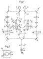
- 1, 1 denotes a light source which illuminates a test mark 3 via a condenser 2.
- a lens system 4 images the test mark 3 to infinity.
- a prism 5 is arranged in the parallel beam path behind the lens system 4 and serves to divide the beam path into two projection beam paths 6 and 7 which are spatially separated from one another, the mirrors 8 and 9 serving to deflect the beam.
- the two projection beam paths 6 and 7 are constructed symmetrically, so that only the beam path 6 is explained below.
- the corresponding elements and functions can also be found in beam path 7.
- the light deflected by the mirror 8 into the projection beam path 6 first passes through an adjustment system which consists of a spherical lens 10 and a Stokes lens 11, which are axially displaceable together, as indicated by the arrow 12.
- the astigmatic effect of the Stokes lens can be changed continuously by means of the operating member 13.
- the resulting spherical component can be compensated for by shifting the setting system 10, 11.
- the test mark 3 is imaged by the lens 10, a lens system 15 and the mirrors 16, 17 onto the retina of the eye 18 to be examined. If this eye has normal vision, the test 3 is imaged by the lens 10 into the focal point of the lens system 15 on the projector side. The eye 18 then images the test mark 3 imaged by the system 15 towards infinity sharply on the retina, i.e. the test subject sees the test mark sharply.
- the mirror 17 arranged in front of the eye 18 is partially transparent, so that the test subject can look at the surroundings in a completely relaxed manner, overlaying the bright test image.
- the lens 10 is shifted axially until the test mark 3 is sharply imaged on the retina of the eye.
- the axial position of the lens 10 is a measure of the spherical refraction.
- Astigmatic ametropia is corrected by operating the Stokes lens 11. It will, as shown, together with the lens 10 axially shifted, since a change in distance between the lenses 10 and 11 would lead to a distortion of the astigmatic correction.
- the position of the operating member 13 is a measure of the astigmatic refraction value sought.
- the two projection beam paths 6 and 7 run laterally from the eyes 18 and 20 in order to avoid device mopia. This requires a large distance between the mirrors 16 and 17.
- the lens system 15 is designed as a telesystem.
- the distance of the lens facing the eye from the pupil of the eye 18 thus becomes a multiple of the focal length of the system 15.
- a displacement path of the setting system 10, 11 of 1 mm corresponds approximately to a change in the refraction value by one diopter.
- the light reflected by the retina of the eye 18 is reflected into the observation beam path 21 via a mirror 14 arranged in the projection beam path 6.
- This mirror is arranged in such a way that the lens system 15 images the pupil of the eye 18 in its plane.
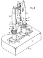
- the mirror 14 has a central, partially transparent area 22 which is surrounded by a reflecting area 23. This area 23 bears a mark 24.
- the projection beam path 6 runs through the central area 23. An exact adjustment of the overall device is achieved when the observer sees the eye pupil in the central area 23 and the mark 24 lies symmetrically to it.
- the mirror 14 can be folded out. This enables the exit pupil of the projection beam path to be enlarged in the case of a subjective eye examination.
- the observation beam path 21 contains an adjustment system 25, 26 which is constructed in the same way as the adjustment system 10, 11 in the projection beam path 6 and which, as arrow 27 shows, is axially displaceable.
- the displacement of the adjustment systems 10, 11 and 25, 26 is coupled.
- the retina of the eye 18 is imaged to infinity by the adjustment system 25, 26.
- a lens system 29 After deflection on the foldable mirror 28, a lens system 29 generates a real image of the retina in the image plane 30.
- a lens 31 is arranged parallel to the setting system 25, 26.
- the light coming from the mirror 14 can be guided over the mirrors 33, 34 and the lens 31 by means of a foldable mirror 32.
- An image of the pupil of the eye 18 is generated in the image plane 30.
- the image plane 30 is observed by means of an observation system, not shown here, for example a binocular tube.
- the image generated in plane 30 is made visible using an image converter.
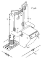
- the device shown in its optical structure in FIG. 1 can be accommodated in a housing, as shown in FIG. 3.
- the elements 2 to 5 are arranged in the base 51, while the tubes 52 and 53 receive the projection beam paths 6 and 7.
- the elements 8 and 10 to 16 are arranged in the tube 52; the partially transparent mirrors 17, 19 are carried by the tubes 52, 53.
- 54 is a headrest for the test subject, which is adjustable in height by means of the rings 35.
- Two rings 36, 37 on the tubes 52, 53 are used to adjust the height of the device.
- the actuating members 38, 40 serve for the axial displacement of the setting systems 10, 11 and the setting systems coupled therewith in the observation beam path 21.
- the members 39, 41 serve for setting the astigmatism.
- the observation beam paths are accommodated in the tube 42, which consists of two parts which can be moved into one another.
- a slide 43 is displaceably arranged on the tube 42 and can optionally be brought into the positions which enable the test mark images generated in the image plane 30 to be viewed.
- the test mark image generated by the right eye 18 is e.g. observed through the opening 44 in the tube 42.
- the correct determination of the refractive condition depends on the corneal vertex distance.
- the device is calibrated to a corneal vertex distance of 16 mm.
- the lens 31 focuses on the location of the mirror 14 or on the mark 24.
- the device is shifted in the direction of the arrows 46 until the pupil of the eye appears simultaneously with the mark 24 in the image plane 30.
- the corneal vertex distance is set correctly.
- a marking (not shown here) which is arranged symmetrically with respect to the pupil of the device and which enables the device to be adjusted to the subject's eyes from the side and height.
- the next step is the objective refraction.
- the setting elements 10, 11 and coupled with them the setting elements 25, 26 are shifted until the test mark 3 appears sharp in the image plane via the actuators 38, 39.
- the observation takes place through the opening 44.
- the test person can observe this setting himself in a controlling manner if light in the visible spectral region is used to project the test mark 3.
- the subject himself or the observer can bring about an optimal correction of the ametropia by actuating the members 38, 39, 40, 41.
- the subject adjusts the device until he sees test mark 3 with both eyes optimally. This adjustment can be made under constant control by observing the image plane 30.
- the device shown also enables a close inspection.
- the projector 1 to 4 is axially shifted until the test mark 3 appears in the plane of the close-up distance (e.g. 400 mm).
- the mirrors 17, 19 are pivoted about the point of rotation of the eye, specifically by the angle by which the eye rotates when looking from a distance into the vicinity.
- FIG. 4 shows an embodiment in which, instead of the observation device 43 of FIG. 3, a projection attachment 47 is used which is fixedly connected to the base 51 and projects the test marks 3a, 3b onto a screen.
- a projection attachment 47 is used which is fixedly connected to the base 51 and projects the test marks 3a, 3b onto a screen.
- Such a device is advantageously used when 3 infrared light is used to project the test mark.
Description
Die vorliegende Erfindung betrifft eine Vorrichtung zur subjektiven und objektiven Refraktionsbestimmung.The present invention relates to a device for subjective and objective refraction determination.
Es sind, z.B. aus «ABC der Optik» 1961, Seiten 742/743 objektiv arbeitende Augenrefraktometer bekannt, bei denen ein Testobjekt auf die Netzhaut des zu untersuchenden Auges abgebildet und das vom Auge reflektierte Licht beobachtet wird. Ein im Beleuchtungsstrahlengang angeordnetes optisches Element, z.B. eine Linse oder ein Prisma, wird solange verschoben, bis das Testbild auf der Netzhaut scharf erscheint, wobei die Stellung dieses Elementes dann ein Mass für den gesuchten Refraktionswert ist.There are e.g. from “ABC der Optik” 1961, pages 742/743, objectively working eye refractometers, in which a test object is imaged on the retina of the eye to be examined and the light reflected by the eye is observed. An optical element arranged in the illumination beam path, e.g. a lens or a prism is shifted until the test image appears sharp on the retina, the position of this element then being a measure of the refraction value sought.
Diese bekannten Geräte haben den Nachteil, dass sie keine gleichzeitige subjektive Refraktionsbestimmung ermöglichen und dass nur eine monokulare Bestimmung möglich ist.These known devices have the disadvantage that they do not allow simultaneous subjective refraction determination and that only a monocular determination is possible.
Aus der DE-PS 1299907 ist ein Gerät zur subjektiven und gleichzeitigen objektiven Refraktionsbestimmung bekannt, bei dem auf eine Bildwand gleichzeitig zwei Testmarken in unterschiedlichen Spektralbereichen projiziert werden und der Proband durch einen Phoropter hindurch diese Bildwand beobachtet. Das von der Netzhaut des Auges reflektierte Licht wird über einen teildurchlässigen Spiegel aus dem Beleuchtungsstrahlengang ausgespiegelt und mittels einer Optik in eine Bildebene abgebildet. Der Beobachter verändert die Phoroptereinstellung so lange, bis das Netzhautbild in der Bildebene scharf erscheint. Der Patient kann durch Beobachten einer der Testmarken die Sehverbesserung verfolgen und kann so selbst an der optimalen Einstellung mitwirken.From DE-PS 1299907 a device for subjective and simultaneous objective refraction determination is known, in which two test marks are simultaneously projected onto different screens in different spectral ranges and the subject observes this screen through a phoropter. The light reflected from the retina of the eye is reflected out of the illuminating beam path via a partially transparent mirror and imaged into an image plane by means of optics. The observer changes the phoropter setting until the retinal image appears sharp in the image plane. The patient can monitor the improvement in vision by observing one of the test marks and can thus participate in the optimal setting himself.
Dieses Gerät hat den Nachteil, dass eine Korrektur nur in diskontinuierlichen Schritten und nur monokular möglich ist und dass durch den vor dem Patientenauge angeordneten Phoropter die bekannte Gerätemyopie auftritt.This device has the disadvantage that correction is only possible in discontinuous steps and only monocularly and that the known device myopia occurs due to the phoropter arranged in front of the patient's eye.
Aus der US-PS 3 927 933 ist ein Gerät zur subjektiven und objektiven Refraktionsbestimmung bekannt, das als sogenanntes Freisichtgerät ausgebildet ist. Bei diesem Gerät wird eine Testmarke über zwei voneinander getrennte Projektionsstrahlengänge auf einen Hohlspiegel abgebildet, der in einer vorgegebenen Entfernung vom Probanden angebracht ist und von diesem beidäugig betrachtet wird. In beiden Projektionsstrahlengängen sind Einstellsysteme mit kontinuierlich veränderbarer sphärischer und astigmatischer Wirkung angeordnet, die solange verstellt werden, bis der Proband die Testmarke scharf sieht. Das von den Probandenaugen reflektierte Licht wird nach Reflexion am Hohlspiegel über einen teildurchlässigen Spiegel in zwei Beobachtungsstrahlengänge ausgespiegelt, welche dieselben Einstellsysteme enthalten wie die Projektionsstrahlengänge.From US Pat. No. 3,927,933 a device for subjective and objective refraction determination is known, which is designed as a so-called clear view device. In this device, a test mark is imaged on a concave mirror via two separate projection beam paths, which is attached at a predetermined distance from the subject and is viewed by the subject with both eyes. Adjustment systems with continuously changeable spherical and astigmatic effects are arranged in both projection beam paths, which are adjusted until the test person sees the test mark sharply. After reflection on the concave mirror, the light reflected by the test person's eyes is reflected by a partially transparent mirror in two observation beam paths, which contain the same adjustment systems as the projection beam paths.
Dieses Gerät hat den Nachteil, dass der Hohlspiegel relativ gross sein muss, damit sich die Pupille der Probandenaugen auf das Testbild einstellen kann, und dass damit das ganze Gerät gross baut. Zur notwendigen Grösse des Gerätes trägt auch bei, dass infolge des grossen Abstandes zwischen den Probandenaugen und dem Hohlspiegel die Verschiebewege der Einstellsysteme gross sind.The disadvantage of this device is that the concave mirror has to be relatively large so that the pupil of the test subject's eyes can adjust to the test pattern, and that the whole device is large. The necessary size of the device also contributes to the fact that, due to the large distance between the test person's eyes and the concave mirror, the displacement paths of the adjustment systems are large.
Es ist nun die Aufgabe der vorliegenden Erfindung eine als Freisicht-Gerät ausgebildete Vorrichtung zur subjektiven und objektiven Refraktionsbestimmung zu schaffen, die besonders kompakt ist und sich durch einen einfachen Aufbau auszeichnet.It is the object of the present invention to provide a device for subjective and objective refraction determination which is designed as a clear view device and which is particularly compact and is distinguished by a simple structure.
Diese Aufgabe wird bei einer Vorrichtung nach dem Oberbegriff des Anspruches 1 dadurch gelöst, dass vor jedem Probandenauge ein teildurchlässiger Spiegel zur Umlenkung des Projektionsstrahlenganges in das Auge und in Lichtrichtung gesehen vor diesem Spiegel und hinter dem Einstellsystem ein Linsensystem angeordnet ist, dessen dem Auge zugewandte Linse von der Augenpupille einen Abstand hat, der ein Mehrfaches der Brennweite des Linsensystems ist, und das zusammen mit dem Auge das Testzeichen auf den Augenhintergrund abbildet, und dass ein zur Ausspiegelung des Beobachtungsstrahlenganges dienender Spiegel in der Ebene des vom Linsensystem erzeugten Bildes der Augenpupille angeordnet ist.This object is achieved in a device according to the preamble of claim 1 in that a partially transparent mirror for deflecting the projection beam path into the eye and seen in the direction of light is arranged in front of this mirror and behind the adjustment system, a lens system, the lens facing the eye has a distance from the eye pupil that is a multiple of the focal length of the lens system and that, together with the eye, images the test symbol on the back of the eye, and that a mirror serving to reflect the observation beam path is arranged in the plane of the image of the eye pupil generated by the lens system .
Der Proband sieht durch die vor seinen Augen angeordneten teildurchlässigen Spiegel das dem Bild der Umgebung überlagerte helle Testzeichen. Um die bekannte Gerätemyopie zu vermeiden darf die Vorrichtung selbst für den Patienten nicht sichtbar sein, d.h. die Projektionsstrahlengänge sollten zweckmässig seitlich der Probandenaugen verlaufen. Dies macht eine Einspiegelung über weitere Spiegel und damit eine verhältnismässig grosse Schnittweite des zur Abbildung der Testmarke dienenden Linsensystems erforderlich. Um die Verschiebewege der Einstellelemente und damit auch die Geräteabmessung klein halten zu können, ist dieses System als TeleSystem ausgebildet, dessen Schnittweite ein Mehrfaches der System-Brennweite ist.The subject sees through the partially transparent mirrors arranged in front of his eyes the bright test symbol superimposed on the image of the surroundings. In order to avoid the known device mythology, the device itself must not be visible to the patient, i.e. the projection beam paths should expediently run to the side of the test person's eyes. This necessitates a reflection via additional mirrors and thus a relatively large focal length of the lens system used to image the test mark. In order to keep the displacement of the setting elements and thus also the device dimensions small, this system is designed as a TeleSystem, the focal length of which is a multiple of the system focal length.
Die relativ kleinen Geräteaustrittspupillen vor den Probandenaugen bedingen eine genaue Ausrichtung des Gerätes auf die Augenpupille. Dies wird durch die Anordnung des zur Ausspiegelung des Beobachtungsstrahlenganges dienenden Umlenkspiegel in der Ebene des vom Tele-System erzeugten Bildes der Augenpupille ermöglicht. Durch Beobachten dieses Spiegels und damit der Augenpupille ist die erforderliche Ausrichtung dann relativ einfach möglich. Dies gilt besonders, wenn der Umlenkspiegel so ausgebildet ist, dass er einen zentralen teildurchlässigen Bereich aufweist, der von einem, eine Marke tragenden spiegelnden Bereich umgeben ist.The relatively small device exit pupils in front of the test person's eyes require the device to be precisely aligned with the eye pupil. This is made possible by the arrangement of the deflecting mirror serving to reflect the observation beam path in the plane of the image of the eye pupil generated by the tele-system. By observing this mirror and thus the eye pupil, the required alignment is then relatively easy. This applies in particular if the deflecting mirror is designed in such a way that it has a central, partially permeable area which is surrounded by a reflecting area bearing a brand.
Es ist vorteilhaft, den Testzeichen-Projektor so auszubilden, dass er das Testzeichen nach Unendlich abbildet. Damit kann in dem vom Projektor kommenden Parallelstrahlengang eine Aufteilung in zwei räumlich voneinander getrennte Projektionsstrahlengänge erfolgen, die zum Zwecke der Justierung und erforderlicher Einstellungen gegeneinander und relativ zum Projektor verschiebbar sind.It is advantageous to design the test mark projector in such a way that it displays the test mark after infinity. This allows a split in the parallel beam path coming from the projector tion in two spatially separate projection beam paths that can be shifted relative to one another and relative to the projector for the purpose of adjustment and required settings.
Um mit der Vorrichtung nach der Erfindung auch Nahprüfungen durchführen zu können, sind der Testzeichen-Projektor oder das Testzeichen oder die Einstellsysteme axial so verschiebbar, dass für den Probanden das Testzeichen in einer Entfernung von beispielsweise 400 mm erscheint, die der Nahprüfentfernung entspricht.In order to be able to carry out close-up tests with the device according to the invention, the test mark projector or the test mark or the setting systems can be displaced axially so that the test symbol appears to the test person at a distance of, for example, 400 mm, which corresponds to the close-up distance.
Da bei einer Nahprüfung die Blickrichtung gesenkt wird und die Augen eine Konvergenzstellung einnehmen, sind bei der Vorrichtung nach der Erfindung die vor den Probanden-Augen angeordneten Spiegel um den Augendrehpunkt schwenkbar. Durch Schwenken dieser Spiegel in Verbindung mit der entsprechenden Verschiebung des Testzeichens in die Nahprüfentfernung wird die zur Nahprüfung erforderliche Augenstellung erreicht. Dabei ist es vorteilhaft, die Spiegel und die Elemente zur Testzeichenverschiebung bewegungsmässig zu koppeln, um eine möglichst einfache Bedienung des Gerätes zu ermöglichen.Since the direction of vision is lowered during a close-up examination and the eyes assume a convergence position, the mirrors arranged in front of the subject's eyes can be pivoted about the eye pivot point in the device according to the invention. By swiveling these mirrors in connection with the corresponding shift of the test mark into the close-up distance, the eye position required for close-up inspection is achieved. It is advantageous to couple the mirrors and the elements for shifting the test characters in terms of movement in order to make the operation of the device as simple as possible.
Es kann weiterhin vorteilhaft sein, die gesamte Vorrichtung zur Nahprüfung kippbar zu lagern.It can also be advantageous to tilt the entire device for close-up inspection.
Zur notwendigen Korrektur der Fehlsichtigkeit sind in beiden Projektions- und beiden Beobachtungsstrahlengängen Einstellsysteme zur kontinuierlichen Einstellung sphärischer und astigmatischer Wirkungen angeordnet. Diese Einstellsysteme sind sehr einfach aufgebaut und bestehen jeweils aus einer sphärischen und einer Stokesschen Linse, die gemeinsam axial verschiebbar sind.For the necessary correction of ametropia, adjustment systems for the continuous adjustment of spherical and astigmatic effects are arranged in both projection and observation beam paths. These adjustment systems are very simple and each consist of a spherical and a Stokes lens, which are axially displaceable together.
Die Einstellsysteme in einem Projektions- und dem zugeordneten Beobachtungsstrahlengang sind jeweils bewegungsmässig gekoppelt.The setting systems in a projection path and the associated observation beam path are each coupled in terms of movement.
Die beiden Beobachtungsstrahlengänge sind jeweils so ausgebildet, dass die von den Augen reflektierte Strahlung in eine Bildebene abgebildet wird. Diese Bildebene wird dann über ein bekanntes Beobachtungssystem, beispielsweise einen Binokulartubus, vom Beobachter betrachtet. Dieser kann unter ständiger Beobachtung durch Verschieben der Einstellsysteme in den Strahlengängen das Testzeichen auf der Netzhaut der Augen scharf abbilden. Der Patient beobachtet dabei in freier und unbehinderter Sicht das Testzeichen und kann die objektive Einstellung durch den Beobachter ständig verfolgen und auch subjektiv korrigieren. Dazu wird zweckmässig nach der objektiven Bestimmung eine subjektive Bestimmung vorgenommen, die der Proband auch selbst durchführen kann.The two observation beam paths are each designed such that the radiation reflected by the eyes is imaged in an image plane. This image plane is then viewed by the observer via a known observation system, for example a binocular tube. Under constant observation, he can sharply image the test mark on the retina of the eyes by moving the adjustment systems in the beam paths. The patient observes the test sign in a clear and unobstructed view and can constantly track the objective attitude by the observer and correct it subjectively. For this purpose, a subjective determination is expediently made after the objective determination, which the test person can also carry out himself.
Mit der neuen Vorrichtung lässt sich also für beide Augen des Probanden unabhängig voneinander eine objektive und subjektive Refraktionsbestimmung durchführen, wobei der Proband freie, unbehinderte Sicht hat. Die Vorrichtung selbst ist kompakt und bedienungsfreundlich aufgebaut und ermöglicht sowohl eine Fern- als auch eine Nahprüfung.With the new device, an objective and subjective refraction determination can thus be carried out independently of one another for both eyes of the test person, the test person having a clear, unobstructed view. The device itself is compact and user-friendly and enables both remote and close inspection.
Die Erfindung wird im folgenden anhand der Fig. 1 bis 4 der beigefügten Zeichnungen näher erläutert. Im einzelnen zeigen:
- Fig. 1 die Anordnung der optischen Elemente bei einem Ausführungsbeispiel;
- Fig. 2 einen der im Beispiel der Fig. 1 verwendeten Spiegel zur Ausspiegelung des Beobachtungsstrahlenganges in Draufsicht;
- Fig. 3 ein Ausführungsbeispiel in perspektivischer Darstellung;
- Fig. 4 ein anderes Ausführungsbeispiel, ebenfalls in perspektivischer Darstellung.
- Figure 1 shows the arrangement of the optical elements in one embodiment.
- FIG. 2 shows a top view of one of the mirrors used in the example of FIG. 1 for reflecting the observation beam path;
- Fig. 3 shows an embodiment in perspective;
- Fig. 4 shows another embodiment, also in perspective.
In Fig. 1 ist mit 1 eine Lichtquelle bezeichnet, die über einen Kondensor 2 eine Testmarke 3 beleuchtet. Ein Linsensystem 4 bildet die Testmarke 3 nach Unendlich ab. Im Parallelstrahlengang hinter dem Linsensystem 4 ist ein Prisma 5 angeordnet, das zur Aufteilung des Strahlenganges in zwei räumlich voneinander getrennte Projektionsstrahlengänge 6 und 7 dient, wobei die Spiegel 8 und 9 zur Strahlumlenkung dienen.1, 1 denotes a light source which illuminates a
Die beiden Projektionsstrahlengänge 6 und 7 sind symmetrisch aufgebaut, so dass im folgenden nur der Strahlengang 6 erläutert wird. Die entsprechenden Elemente und Funktionen finden sich ebenso im Strahlengang 7.The two
Das vom Spiegel 8 in den Projektionsstrahlengang 6 umgelenkte Licht tritt zunächst durch ein Einstellsystem, das aus einer sphärischen Linse 10 und einer Stokesschen Linse 11 besteht, die gemeinsam axial verschiebbar sind, wie dies durch den Pfeil 12 angedeutet ist. Mittels des Bedienungsgliedes 13 kann die astigmatische Wirkung der Stokesschen Linse kontinuierlich verändert werden. Der dabei entstehende sphärische Anteil kann durch Verschieben des Einstellsystems 10, 11 kompensiert werden.The light deflected by the mirror 8 into the
Die Testmarke 3 wird von der Linse 10, einem Linsensystem 15 und den Spiegeln 16, 17 auf die Netzhaut des zu prüfenden Auges 18 abgebildet. Ist dieses Auge normalsichtig, so wird der Test 3 von der Linse 10 in den projektorseitigen Brennpunkt des Linsensystems 15 abgebildet. Das Auge 18 bildet dann die vom System 15 nach Unendlich abgebildete Testmarke 3 scharf auf der Netzhaut ab, d.h. der Proband sieht die Testmarke scharf. Der vor dem Auge 18 angeordnete Spiegel 17 ist teildurchlässig, so dass der Proband völlig entspannt die Umgebung betrachten kann, der sich das helle Testbild überlagert.The
Zur Refraktionsprüfung von Kindern können diesen beispielsweise bewegte Bilder gezeigt werden, welche eine Akkomodationsentspannung herbeiführen.For refraction testing of children, for example, moving images can be shown, which bring about relaxation in accommodation.
Ist das zu prüfende Auge 18 nicht normalsichtig, so wird die Linse 10 axial solange verschoben, bis die Testmarke 3 scharf auf der Netzhaut des Auges abgebildet wird. Die axiale Stellung der Linse 10 ist ein Mass für die sphärische Refraktion.If the
Astigmatische Fehlsichtigkeiten werden durch Betätigen der Stokesschen Linse 11 korrigiert. Sie wird, wie dargestellt, zusammen mit der Linse 10 axial verschoben, da eine Abstandsänderung zwischen den Linsen 10 und 11 zu einer Verfälschung der astigmatischen Korrektion führen würde.Astigmatic ametropia is corrected by operating the
Die Stellung des Bedienungsgliedes 13 ist ein Mass für den gesuchten astigmatischen Refraktionswert.The position of the operating
Die beiden Projektionsstrahlengänge 6 und 7 verlaufen seitlich von den Augen 18 und 20, um eine Gerätemyopie zu vermeiden. Dies bedingt einen grossen Abstand zwischen den Spiegeln 16 und 17. Um zu vermeiden, dass dadurch der Verschiebeweg für das Einstellsystem 10, 11 und damit das ganze Gerät gross wird, ist das Linsensystem 15 als Telesystem ausgebildet. Damit wird der Abstand der dem Auge zugewandten Linse von der Pupille des Auges 18 ein Mehrfaches der Brennweite des Systems 15. Es ist beispielsweise möglich, dem Linsensystem 15 eine Schnittweite von 200 mm bei einer Brennweite von 31 mm zu geben. Mit einer solchen Ausbildung entspricht ein Verschiebeweg des Einstellsystems 10, 11 von 1 mm etwa einer Änderung des Refraktionswertes um eine Dioptrie.The two
Das von der Netzhaut des Auges 18 reflektierte Licht wird über einen im Projektionsstrahlengang 6 angeordneten Spiegel 14 in den Beobachtungsstrahlengang 21 ausgespiegelt. Dieser Spiegel ist so angeordnet, dass das Linsensystem 15 die Pupille des Auges 18 in seine Ebene abbildet.The light reflected by the retina of the
Der Spiegel 14 weist, wie Fig. 2 zeigt, einen zentralen teildurchlässigen Bereich 22 auf, der von einem spiegelnden Bereich 23 umgeben ist. Dieser Bereich 23 trägt eine Marke 24. Der Projektionsstrahlengang 6 verläuft durch den zentralen Bereich 23. Eine exakte Justierung der Gesamtvorrichtung ist erreicht, wenn der Beobachter die Augenpupille im Zentralbereich 23 liegen sieht und die Marke 24 symmetrisch dazu liegt.As shown in FIG. 2, the
Der Spiegel 14 ist ausklappbar. Damit kann die Austrittspupille des Projektionsstrahlenganges bei subjektiver Augenprüfung vergrössert werden.The
Der Beobachtungsstrahlengang 21 enthält ein Einstellsystem 25, 26, das ebenso aufgebaut ist wie das Einstellsystem 10, 11 im Projektionsstrahlengang 6 und das, wie Pfeil 27 zeigt, axial verschiebbar ist. Die Verschiebung der Einstellsysteme 10, 11 und 25, 26 ist gekoppelt. Durch das Einstellsystem 25, 26 wird die Netzhaut des Auges 18 nach Unendlich abgebildet. Nach Umlenkung am klappbaren Spiegel 28 erzeugt ein Linsensystem 29 ein reelles Bild der Netzhaut in der Bildebene 30.The
Parallel zum Einstellsystem 25, 26 ist eine Linse 31 angeordnet. Mittels eines klappbaren Spiegels 32 kann das vom Spiegel 14 kommende Licht über die Spiegel 33, 34 und die Linse 31 geführt werden. Dabei wird ein Bild der Pupille des Auges 18 in der Bildebene 30 erzeugt.A
Die Bildebene 30 wird mittels eines hier nicht dargestellten Beobachtungssystems, beispielsweise eines Binokulartubus, beobachtet.The
Es ist möglich eine Lichtquelle 1 zu verwenden, die infrarotes Licht erzeugt. In diesem Fall wird das in der Ebene 30 erzeugte Bild über einen Bildwandler sichtbar gemacht.It is possible to use a light source 1 that generates infrared light. In this case, the image generated in
Die in ihrem optischen Aufbau in Fig. 1 dargestellte Vorrichtung kann in einem Gehäuse untergebracht sein, wie es in Fig. 3 gezeigt ist. Die Elemente 2 bis 5 sind in der Basis 51 angeordnet, während die Rohre 52 und 53 die Projektionsstrahlengänge 6 und 7 aufnehmen. Die Elemente 8 und 10 bis 16 sind im Rohr 52 angeordnet; die teildurchlässigen Spiegel 17, 19 werden von den Rohren 52, 53 getragen. Mit 54 ist eine Kopfstütze für den Probanden bezeichnet, die mittels der Ringe 35 höhenverstellbar ist. Zwei Ringe 36, 37 auf den Rohren 52, 53 dienen zur Höhenverstellung des Gerätes.The device shown in its optical structure in FIG. 1 can be accommodated in a housing, as shown in FIG. 3. The elements 2 to 5 are arranged in the
Die Betätigungsglieder 38, 40 dienen zur Axialverschiebung der Einstellsysteme 10, 11 und der damit gekoppelten Einstellsysteme im Beobachtungsstrahlengang 21. Die Glieder 39, 41 dienen zur Einstellung des Astigmatismus.The
Die Beobachtungsstrahlengänge sind im Rohr 42 untergebracht, das aus zwei ineinander verschiebbaren Teilen besteht. Auf dem Rohr 42 ist verschiebbar ein Schlitten 43 angeordnet, der wahlweise in die Positionen gebracht werden kann, die eine Betrachtung der in der Bildebene 30 erzeugten Testmarken-Bilder ermöglicht. Das vom rechten Auge 18 erzeugte Testmarkenbild ist z.B. über die Öffnung 44 im Rohr 42 zu beobachten.The observation beam paths are accommodated in the
Die Wirkungsweise des Gerätes nach Fig. 1 und 2 ist folgende:
- Nachdem der Proband seinen Platz eingenommen und Kopfstütze 54 sowie Gerät in der Höhe richtig eingestellt sind, wird durch Verschieben der Rohre 52, 53 auf der Basis 51 (Pfeile 45) die Pupillendistanz eingestellt.
- After the test person has taken his place and the
headrest 54 and the device have been correctly adjusted in height, the pupil distance is adjusted by moving thetubes
Die richtige Bestimmung des Refraktionszustandes ist abhängig vom Hornhautscheitelabstand. Das Gerät ist beispielsweise auf einen Hornhautscheitelabstand von 16 mm geeicht. Zunächst wird mittels der Linse 31 auf den Ort des Spiegels 14 bzw. auf die Marke 24fokussiert. Danach wird bei feststehender Linse 31 das Gerät in Richtung der Pfeile 46 solange verschoben, bis die Pupille des Auges zugleich mit der Marke 24 in der Bildebene 30 scharf erscheint. Damit ist der Hornhautscheitelabstand richtig eingestellt. In der Bildebene 30 ist eine, hier nicht dargestellte, zur Gerätepupille symmetrisch angeordnete Markierung vorgesehen, welche die Einstellung des Gerätes zu den Probanden-Augen nach Seite und Höhe ermöglicht.The correct determination of the refractive condition depends on the corneal vertex distance. For example, the device is calibrated to a corneal vertex distance of 16 mm. First, the
Als nächster Schritt wird die objektive Refraktion vorgenommen. Dazu werden über die Betätigungsglieder 38, 39 die Einstellelemente 10, 11 und gekoppelt damit die Einstellelemente 25, 26 solange verschoben, bis die Testmarke 3 in der Bildebene scharf erscheint. Die Beobachtung erfolgt durch die Öffnung 44. Der Proband kann diese Einstellung selbst kontrollierend beobachten, wenn Licht im sichtbaren Spektralgebiet zur Projektion der Testmarke 3 verwendet wird.The next step is the objective refraction. For this purpose, the setting
Nach erfolgter Einstellung wird der Schlitten 43 nach rechts verschoben und durch Betätigen der Glieder 40, 41 wird solange eingestellt, bis die vom Auge 20 reflektierte Testmarke in der Bildebene 30 scharf erscheint.After setting, the
Nach Abschluss der objektiven Refraktion kann der Proband selbst oder der Beobachter durch Betätigen der Glieder 38, 39, 40, 41 eine optimale Korrektion der Fehlsichtigkeit herbeiführen. Der Proband verstellt dazu das Gerät solange, bis er die Testmarke 3 mit beiden Augen optimal scharf sieht. Diese Einstellung kann unter ständiger Kontrolle durch Beobachten der Bildebene 30 erfolgen.After completion of the objective refraction, the subject himself or the observer can bring about an optimal correction of the ametropia by actuating the
Das gezeigte Gerät ermöglicht auch eine Nahprüfung. Dazu wird z.B. der Projektor 1 bis 4 solange axial verschoben, bis die Testmarke 3 in der Ebene der Nahprüfentfernung (z.B. 400 mm) erscheint. Zugleich werden die Spiegel 17, 19 um den Augendrehpunkt geschwenkt, und zwar um den Winkel, um den sich das Auge beim Blick von der Ferne in die Nähe dreht. Nach Abschluss dieser Arbeiten wird in der bechriebenen Weise der erforderliche Nahzusatz objektiv und/oder subjektiv bestimmt.The device shown also enables a close inspection. For this, e.g. the projector 1 to 4 is axially shifted until the
Fig. 4 zeigt ein Ausführungsbeispiel, bei dem anstelle der Beobachtungsvorrichtung 43 der Fig. 3 ein fest mit der Basis 51 verbundener Projektionszusatz 47 verwendet ist, der die Testmarken 3a, 3b auf einen Bildschirm projiziert. Ein solches Gerät findet vorteilhaft Anwendung, wenn zur Projektion der Testmarke 3 infrarotes Licht verwendet wird.FIG. 4 shows an embodiment in which, instead of the
Claims (10)
Applications Claiming Priority (2)
| Application Number | Priority Date | Filing Date | Title |
|---|---|---|---|
| DE19803045139 DE3045139A1 (en) | 1980-11-29 | 1980-11-29 | DEVICE FOR SUBJECTIVE AND OBJECTIVE REFLECTION DETERMINATION |
| DE3045139 | 1980-11-29 |
Publications (2)
| Publication Number | Publication Date |
|---|---|
| EP0053680A1 EP0053680A1 (en) | 1982-06-16 |
| EP0053680B1 true EP0053680B1 (en) | 1984-03-07 |
Family
ID=6117962
Family Applications (1)
| Application Number | Title | Priority Date | Filing Date |
|---|---|---|---|
| EP81108496A Expired EP0053680B1 (en) | 1980-11-29 | 1981-10-19 | Device for objective and subjective refraction measurement |
Country Status (4)
| Country | Link |
|---|---|
| US (1) | US4465348A (en) |
| EP (1) | EP0053680B1 (en) |
| JP (1) | JPS57117828A (en) |
| DE (2) | DE3045139A1 (en) |
Families Citing this family (39)
| Publication number | Priority date | Publication date | Assignee | Title |
|---|---|---|---|---|
| JPS5944237A (en) * | 1982-09-03 | 1984-03-12 | 株式会社ニコン | Self-feeling eye inspecting apparatus |
| JPS5980227A (en) * | 1982-10-29 | 1984-05-09 | 株式会社ニデツク | Apparatus for measuring refractive force of eye |
| JPS5985643A (en) * | 1982-11-06 | 1984-05-17 | 株式会社トプコン | Remotely and nearly usable refractive index measuring apparatus |
| JPS5985642A (en) * | 1982-11-06 | 1984-05-17 | 株式会社トプコン | Self-conscious refractive index measuring apparatus |
| DE3315939A1 (en) * | 1983-05-02 | 1984-11-08 | Oculus-Optikgeräte GmbH, 6330 Wetzlar | DEVICE FOR EYE FACTION DETERMINATION |
| JPS6092730A (en) * | 1983-10-26 | 1985-05-24 | 株式会社トプコン | Eye position inspector |
| JPS60210237A (en) * | 1984-04-05 | 1985-10-22 | 株式会社トプコン | Eye refraction force measuring apparatus |
| JPS60222028A (en) * | 1984-04-19 | 1985-11-06 | 株式会社トプコン | Eye refrection inspection apparatus |
| DD226187A1 (en) * | 1984-08-01 | 1985-08-21 | Zeiss Jena Veb Carl | DEVICE FOR THE TESTING OF SHEAR AND BINOCULAR SHOW |
| JPS6399835A (en) * | 1987-05-29 | 1988-05-02 | 株式会社 ニデック | Subjective eye refractive power measuring apparatus |
| JPS63119738A (en) * | 1987-10-07 | 1988-05-24 | 株式会社ニデック | Objective ophthalmoscope |
| DD273771B5 (en) * | 1988-07-11 | 1997-01-23 | Carn Zeiss Jena Gmbh | Method and arrangement for Nahglillenbestimmung |
| US6522939B1 (en) * | 1996-07-01 | 2003-02-18 | Robert D. Strauch | Computer system for quality control correlation |
| US7303281B2 (en) * | 1998-10-07 | 2007-12-04 | Tracey Technologies, Llc | Method and device for determining refractive components and visual function of the eye for vision correction |
| UA67870C2 (en) | 2002-10-04 | 2004-07-15 | Сергій Васильович Молебний | Method for measuring wave aberrations of eyes |
| IL137635A0 (en) * | 2000-08-01 | 2001-10-31 | Visionix Ltd | Apparatus for interactive optometry |
| EP1379158B1 (en) * | 2001-04-16 | 2015-01-21 | Tracey Technologies, Llc | Method for determining clinical refraction of eye from objective source |
| EP1444945B1 (en) * | 2001-11-13 | 2017-03-22 | Kabushiki Kaisha TOPCON | Optometric device |
| WO2003041572A1 (en) * | 2001-11-15 | 2003-05-22 | Kabushiki Kaisha Topcon | Ophthalmologic apparatus and ophthalmologic chart |
| GB2376634B (en) * | 2002-07-13 | 2003-12-10 | Litechnica Ltd | Laser accessory for a binocular indirect ophthalmoscope and binocular indirect ophthalmoscope |
| EP1861635B1 (en) | 2005-03-21 | 2010-11-24 | Litens Automotive Partnership | Belt tensioner with wear compensation |
| US7699471B2 (en) * | 2006-02-14 | 2010-04-20 | Lai Shui T | Subjective refraction method and device for correcting low and higher order aberrations |
| US7726811B2 (en) | 2006-02-14 | 2010-06-01 | Lai Shui T | Subjective wavefront refraction using continuously adjustable wave plates of Zernike function |
| US7959284B2 (en) * | 2006-07-25 | 2011-06-14 | Lai Shui T | Method of making high precision optics having a wavefront profile |
| US8025403B2 (en) * | 2007-02-23 | 2011-09-27 | Mimo Ag | Ophthalmologic apparatus for imaging an eye by optical coherence tomography |
| EP2194903B1 (en) | 2007-09-06 | 2017-10-25 | Alcon LenSx, Inc. | Precise targeting of surgical photodisruption |
| US9492322B2 (en) * | 2009-11-16 | 2016-11-15 | Alcon Lensx, Inc. | Imaging surgical target tissue by nonlinear scanning |
| US8265364B2 (en) | 2010-02-05 | 2012-09-11 | Alcon Lensx, Inc. | Gradient search integrated with local imaging in laser surgical systems |
| US8414564B2 (en) | 2010-02-18 | 2013-04-09 | Alcon Lensx, Inc. | Optical coherence tomographic system for ophthalmic surgery |
| US8398236B2 (en) * | 2010-06-14 | 2013-03-19 | Alcon Lensx, Inc. | Image-guided docking for ophthalmic surgical systems |
| US9532708B2 (en) | 2010-09-17 | 2017-01-03 | Alcon Lensx, Inc. | Electronically controlled fixation light for ophthalmic imaging systems |
| US8459794B2 (en) | 2011-05-02 | 2013-06-11 | Alcon Lensx, Inc. | Image-processor-controlled misalignment-reduction for ophthalmic systems |
| US9622913B2 (en) | 2011-05-18 | 2017-04-18 | Alcon Lensx, Inc. | Imaging-controlled laser surgical system |
| US8398238B1 (en) | 2011-08-26 | 2013-03-19 | Alcon Lensx, Inc. | Imaging-based guidance system for ophthalmic docking using a location-orientation analysis |
| US9023016B2 (en) | 2011-12-19 | 2015-05-05 | Alcon Lensx, Inc. | Image processor for intra-surgical optical coherence tomographic imaging of laser cataract procedures |
| US9066784B2 (en) | 2011-12-19 | 2015-06-30 | Alcon Lensx, Inc. | Intra-surgical optical coherence tomographic imaging of cataract procedures |
| JP6537843B2 (en) | 2014-05-28 | 2019-07-03 | 株式会社トプコン | Optometry device, awareness measurement method using chart for optometry |
| CN106963335B (en) * | 2015-11-13 | 2022-01-04 | 尼德克株式会社 | Subjective eye examination device |
| EP3355102A1 (en) | 2017-01-27 | 2018-08-01 | Carl Zeiss Vision International GmbH | Computer-implemented method for determining centring parameters |
Family Cites Families (5)
| Publication number | Priority date | Publication date | Assignee | Title |
|---|---|---|---|---|
| US2798408A (en) * | 1953-03-09 | 1957-07-09 | American Optical Corp | Vision testing devices |
| US3524702A (en) * | 1968-09-06 | 1970-08-18 | John G Bellows | Apparatus for objectively and automatically refracting the eye |
| US3874774A (en) * | 1973-06-20 | 1975-04-01 | Humphrey Research Associates I | Eye test apparatus |
| US3927933A (en) * | 1973-08-06 | 1975-12-23 | Humphrey Instruments Inc | Apparatus for opthalmological prescription readout |
| US4105302A (en) * | 1976-06-23 | 1978-08-08 | Tate Jr George W | Automatic refraction apparatus and method |
-
1980
- 1980-11-29 DE DE19803045139 patent/DE3045139A1/en not_active Withdrawn
-
1981
- 1981-10-19 EP EP81108496A patent/EP0053680B1/en not_active Expired
- 1981-10-19 DE DE8181108496T patent/DE3162527D1/en not_active Expired
- 1981-11-24 US US06/324,403 patent/US4465348A/en not_active Expired - Fee Related
- 1981-11-30 JP JP56190975A patent/JPS57117828A/en active Pending
Also Published As
| Publication number | Publication date |
|---|---|
| DE3045139A1 (en) | 1982-07-01 |
| EP0053680A1 (en) | 1982-06-16 |
| JPS57117828A (en) | 1982-07-22 |
| DE3162527D1 (en) | 1984-04-12 |
| US4465348A (en) | 1984-08-14 |
Similar Documents
| Publication | Publication Date | Title |
|---|---|---|
| EP0053680B1 (en) | Device for objective and subjective refraction measurement | |
| DE2843287C2 (en) | ||
| EP1389943B1 (en) | Ophthalmoscope | |
| DE202005021287U1 (en) | Aberrometer with vision system | |
| DE102005032501A1 (en) | Instrument for the examination of a patient's eye combines the functions of a slit lamp and an ophthalmoscope, to examine the eye structure from the front to the back | |
| EP0065750B1 (en) | Portable ophthalmoscopic apparatus for the examination of the anterior and posterior parts of the eye | |
| EP0363610B1 (en) | Device for examining the visual functions of a human eye | |
| EP0492044B1 (en) | Vision test device | |
| DE4240583A1 (en) | Apparatus for examination and photography of corneal endothelium - has three optical systems for illuminating cornea and processing reflections for image forming and automatic photography. | |
| DE19501415C2 (en) | Eye test device | |
| WO1993014691A1 (en) | Refraction device for the subjective determination of the spherical and astigmatic sight properties of the eye | |
| EP0029203A1 (en) | Ophthalmological device for investigating anterior and posterior segments of the eye | |
| EP0608516B1 (en) | Ophthalmoscope | |
| EP0004566B1 (en) | Apparatus for displaying optotypes | |
| DE19502337C2 (en) | Device and method for testing visual functions | |
| DE19540802A1 (en) | Device for testing at least one visual function in eye of patient | |
| DE3437234C2 (en) | Device for determining the potential visual acuity using a slit lamp microscope | |
| EP0038525B1 (en) | Ocular refractometry apparatus | |
| DE4422071B4 (en) | Retinal blood flow velocity measuring device | |
| CH646322A5 (en) | DEVICE FOR SUBJECTIVE REFRACTION DETERMINATION. | |
| DD269781A1 (en) | ARRANGEMENT FOR MEASUREMENT ON EYE BACKGROUND | |
| DE2940519C2 (en) | Device for subjective refraction determination | |
| DE3818331C2 (en) | Arrangement and method for high-resolution ophthalmoscopy | |
| WO2023021158A1 (en) | Device and method for orientation of an eye | |
| DE610076C (en) | Ophthalmoscope |
Legal Events
| Date | Code | Title | Description |
|---|---|---|---|
| PUAI | Public reference made under article 153(3) epc to a published international application that has entered the european phase |
Free format text: ORIGINAL CODE: 0009012 |
|
| AK | Designated contracting states |
Designated state(s): CH DE FR GB |
|
| 17P | Request for examination filed |
Effective date: 19820422 |
|
| GRAA | (expected) grant |
Free format text: ORIGINAL CODE: 0009210 |
|
| AK | Designated contracting states |
Designated state(s): CH DE FR GB LI |
|
| REF | Corresponds to: |
Ref document number: 3162527 Country of ref document: DE Date of ref document: 19840412 |
|
| ET | Fr: translation filed | ||
| PGFP | Annual fee paid to national office [announced via postgrant information from national office to epo] |
Ref country code: DE Payment date: 19841027 Year of fee payment: 4 |
|
| PGFP | Annual fee paid to national office [announced via postgrant information from national office to epo] |
Ref country code: FR Payment date: 19841031 Year of fee payment: 4 |
|
| PGFP | Annual fee paid to national office [announced via postgrant information from national office to epo] |
Ref country code: CH Payment date: 19841109 Year of fee payment: 4 |
|
| PLBE | No opposition filed within time limit |
Free format text: ORIGINAL CODE: 0009261 |
|
| STAA | Information on the status of an ep patent application or granted ep patent |
Free format text: STATUS: NO OPPOSITION FILED WITHIN TIME LIMIT |
|
| 26N | No opposition filed | ||
| PG25 | Lapsed in a contracting state [announced via postgrant information from national office to epo] |
Ref country code: LI Effective date: 19861031 Ref country code: CH Effective date: 19861031 |
|
| PG25 | Lapsed in a contracting state [announced via postgrant information from national office to epo] |
Ref country code: FR Free format text: LAPSE BECAUSE OF NON-PAYMENT OF DUE FEES Effective date: 19870630 |
|
| REG | Reference to a national code |
Ref country code: CH Ref legal event code: PL |
|
| GBPC | Gb: european patent ceased through non-payment of renewal fee | ||
| PG25 | Lapsed in a contracting state [announced via postgrant information from national office to epo] |
Ref country code: DE Effective date: 19870701 |
|
| REG | Reference to a national code |
Ref country code: FR Ref legal event code: ST |
|
| PG25 | Lapsed in a contracting state [announced via postgrant information from national office to epo] |
Ref country code: GB Effective date: 19881118 |