EP0051904A2 - Control circuit and fuel burner incorporating a control circuit - Google Patents
Control circuit and fuel burner incorporating a control circuit Download PDFInfo
- Publication number
- EP0051904A2 EP0051904A2 EP81300702A EP81300702A EP0051904A2 EP 0051904 A2 EP0051904 A2 EP 0051904A2 EP 81300702 A EP81300702 A EP 81300702A EP 81300702 A EP81300702 A EP 81300702A EP 0051904 A2 EP0051904 A2 EP 0051904A2
- Authority
- EP
- European Patent Office
- Prior art keywords
- circuit
- signal
- supervisory circuit
- produce
- input
- Prior art date
- Legal status (The legal status is an assumption and is not a legal conclusion. Google has not performed a legal analysis and makes no representation as to the accuracy of the status listed.)
- Granted
Links
Images

Classifications
-
- G—PHYSICS
- G06—COMPUTING; CALCULATING OR COUNTING
- G06F—ELECTRIC DIGITAL DATA PROCESSING
- G06F11/00—Error detection; Error correction; Monitoring
- G06F11/07—Responding to the occurrence of a fault, e.g. fault tolerance
- G06F11/0703—Error or fault processing not based on redundancy, i.e. by taking additional measures to deal with the error or fault not making use of redundancy in operation, in hardware, or in data representation
- G06F11/0751—Error or fault detection not based on redundancy
- G06F11/0754—Error or fault detection not based on redundancy by exceeding limits
- G06F11/0757—Error or fault detection not based on redundancy by exceeding limits by exceeding a time limit, i.e. time-out, e.g. watchdogs
Definitions
- This invention relates to control circuits and, in particular, to self-testing or fail-safe control circuits. It finds application in supply controls for fuel burners, especially gas burners.
- Microprocessor-based controls have the facility to meet these requirements and also offer potential advantages by way of flexibility of start-up program, improved presentation of data to the operator and scope for using the control unit to undertake other process control functions such as temperature and fuel/air ratio.
- Computers used as part of a control system will have several reset requirements. These include power-on reset, operator-generated reset, power-loss reset and a time-out reset. The last requirement is frequently embodied as a watch-dog timer, and in the case of a fail-safe system, the watch-dog timer could halt the processor when it is not re-triggered. If a high degree of safety is required then all of the circuits must be fail-safe or testable during normal operation of the control. A control circuit which meets these requirements has been devised.
- a supervisory circuit for a control system having an output adapted to be brought to a predefined stated in the event of failure of a component or or malfunctioning of the system, or the supervisory circuit, including first input means responsive to a predetermined input signal to produce a trigger pulse in response thereto, resettable monostable circuit means responsive to said trigger pulse to produce an alternating output signal in response to a predetermined sequence of trigger pulses and pump circuit means responsive to said alternating signal to produce a first output signal and to the absence of said alternating signal to produce a second output signal.
- Figure 1 is a block diagram of a typical eight-bit microprocessor. Data are manipulated within the microprocessor and are transferred in and out by way of a data bus DO-D7. Proper operation required that timing and control signals be provided to accomplish specific functions and that other signal lines be monitored by external circuits to determine the state of the processor. Basic system timing is provided by two clock inputs ⁇ 1 , X 2 which accept a two- phase non-overlapping clock that runs at the rail level.
- a suitable "circuit to control the microprocessor is shown in Figure 2.
- An alternating current supply line is fed to the input AC of a rectifier P.
- the rectified output passes by way of a voltage regulator VR to the supply rail V cc of the microprocessor.
- the unregulated output of the rectifier is monitored by a potential divider R1, R3 in series with a zener diode D1.
- the voltage across the zener diode is higher than its characteristic voltage and it conducts, turning on a transistor switch T1 coupled to its anode.
- An inverter IC8 with Schmitt trigger input is connected to the collector load resistor R4 and its output goes high whenever the transistor conducts.
- the inverter is coupled by way of a diode D2 to a second inverter IC9.
- this diode is reverse biased and the further inverter's output is low. If the voltage across the zener diode D1 drops below the zener voltage, it ceases to conduct and the base current to the transistor T1 is cut off. The transistor switches off, the input to the first inverter goes high and its output goes low, forward biasing the output diode and discharging its reservoir capacitor C1.
- a third inverter IC10 is coupled to the second inverter IC9 and together they act as a non-inverting buffer to provide a low, power-on reset signal to the microprocessor.
- the capacitor C1 at the input to the second inverter is connected to the microprocessor's power supply V through a cc resistor R5, maintaining the second inverter's input below its switching point for a time determined by the time constant of the circuit R5C1.
- This signal is inverted by the second inverter IC9 and re-inverted by the third inverter IC10 to give the low reset signal required by the microprocessor.
- a further connection to the base of the first transistor T1 by way of a limiter resistor R2 provides an operator reset facility. Normally the input is left floating, but when it is grounded, it biases the base potential divider R1, R2 to give a low voltage signal equivalent to a power-down reset.
- a watch-dog timer comprising a diode pump circuit. Pulses from the microprocessor are'fed by way of a combination of NAND and NOR-gates IC1-IC5, a switching transistor T2 and inverter IC7 to a diode pump circuit. If this pump circuit is not continuously exercised by the microprocessor, it triggers the HALT input of the microprocessor, switching off the controller.
- the input gates IC1-IC5 decode information from the data and control bus, to present a high signal to the switching transistor T2 only when a particular data word is written to a specific address location.
- This signal is short (less than a microsecond) but is sufficiently long to turn on the switching transistor T2, discharging a reservoir capacitor C3, which charges again when the transistor switches _off.
- the charging time is controlled by the time constant R8C3 set by the collector load resistor R8.
- the microprocessor is programmed to trigger the watch-dog timer at such a rate as to generate a square wave with approximately 50% duty cycle at the output of the inverter IC7.
- This square wave is used to switch a transistor T3 driving the diode pump circuit C4, C5, D7, D8.
- the output voltage of the pump circuit is substantially constant only when an alternating voltage is applied to the input. If the alternating voltage ceases or a component in the diode pump circuit fails, then a shunt resistor R11 will discharge the reservoir capacitor C5 and pull the output low, thereby halting the microprocessor. Likewise, if the diode pump trigger rate is too low, the reservoir capacitor will not charge sufficiently to hold the microprocessor on.
- the microprocessor triggers the watch-dog timer too frequently then the-input resettable monostable T2, C3, R8, IC7.has no chance to time-out so a direct voltage is supplied to the switching transistor T3 and the diode pump circuit will not operate.
- a non-resettable monostable C2, D4, R6, IC6 triggered by the RESET circuit provides an alternative input to the diode pump circuit which provides the necessary input signal on start-up when the microprocessor output is inhibited. This ensures that the HALT signal to the microprocessor is removed for a sufficient time to permit the program execution to commence, re-triggering the watch-dog timer.
- the output of the watch-dog timer is monitored by an inverter circuit IC11 which drives a light-emitting diode LED to provide a visual indication to the operator that the control circuit is functioning normally.
Landscapes
- Engineering & Computer Science (AREA)
- Theoretical Computer Science (AREA)
- Quality & Reliability (AREA)
- Physics & Mathematics (AREA)
- General Engineering & Computer Science (AREA)
- General Physics & Mathematics (AREA)
- Debugging And Monitoring (AREA)
- Regulation And Control Of Combustion (AREA)
- Testing Electric Properties And Detecting Electric Faults (AREA)
Abstract
Description
- This invention relates to control circuits and, in particular, to self-testing or fail-safe control circuits. It finds application in supply controls for fuel burners, especially gas burners.
- Present-day fuel burner control systems are subject to very stringent safety requirements. Microprocessor-based controls have the facility to meet these requirements and also offer potential advantages by way of flexibility of start-up program, improved presentation of data to the operator and scope for using the control unit to undertake other process control functions such as temperature and fuel/air ratio.
- Computers used as part of a control system will have several reset requirements. These include power-on reset, operator-generated reset, power-loss reset and a time-out reset. The last requirement is frequently embodied as a watch-dog timer, and in the case of a fail-safe system, the watch-dog timer could halt the processor when it is not re-triggered. If a high degree of safety is required then all of the circuits must be fail-safe or testable during normal operation of the control. A control circuit which meets these requirements has been devised.
- According to the present invention there is provided a supervisory circuit for a control system having an output adapted to be brought to a predefined stated in the event of failure of a component or or malfunctioning of the system, or the supervisory circuit, including first input means responsive to a predetermined input signal to produce a trigger pulse in response thereto, resettable monostable circuit means responsive to said trigger pulse to produce an alternating output signal in response to a predetermined sequence of trigger pulses and pump circuit means responsive to said alternating signal to produce a first output signal and to the absence of said alternating signal to produce a second output signal.
- An embodiment of the invention will now be described by way of example with reference to the accompanying drawings in which:-
- Figure 1 is a block diagram showing the architecture of a typical eight-bit microprocessor, and
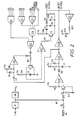
- Figure 2 is a diagram of a watch-dog timer and reset circuits suitable for use with the microprocessor.
- Referring now to the drawings, Figure 1 is a block diagram of a typical eight-bit microprocessor. Data are manipulated within the microprocessor and are transferred in and out by way of a data bus DO-D7. Proper operation required that timing and control signals be provided to accomplish specific functions and that other signal lines be monitored by external circuits to determine the state of the processor. Basic system timing is provided by two clock inputs φ1, X2 which accept a two- phase non-overlapping clock that runs at the rail level.
- A suitable "circuit to control the microprocessor is shown in Figure 2. An alternating current supply line is fed to the input AC of a rectifier P. The rectified output passes by way of a voltage regulator VR to the supply rail Vcc of the microprocessor. The unregulated output of the rectifier is monitored by a potential divider R1, R3 in series with a zener diode D1. In normal operation, the voltage across the zener diode is higher than its characteristic voltage and it conducts, turning on a transistor switch T1 coupled to its anode. An inverter IC8 with Schmitt trigger input, is connected to the collector load resistor R4 and its output goes high whenever the transistor conducts. The inverter is coupled by way of a diode D2 to a second inverter IC9. When the output is high, this diode is reverse biased and the further inverter's output is low. If the voltage across the zener diode D1 drops below the zener voltage, it ceases to conduct and the base current to the transistor T1 is cut off. The transistor switches off, the input to the first inverter goes high and its output goes low, forward biasing the output diode and discharging its reservoir capacitor C1.
- A third inverter IC10 is coupled to the second inverter IC9 and together they act as a non-inverting buffer to provide a low, power-on reset signal to the microprocessor. The capacitor C1 at the input to the second inverter is connected to the microprocessor's power supply V through a cc resistor R5, maintaining the second inverter's input below its switching point for a time determined by the time constant of the circuit R5C1. This signal is inverted by the second inverter IC9 and re-inverted by the third inverter IC10 to give the low reset signal required by the microprocessor. When the voltage at the input to the second inverter rises above its switching point, then the reset line to the microprocessor is brought high and the computer can execute its program. When power is removed a parallel diode D3 acts as a discharge path, whilst a further diode D2 blocks the alternative charging route through the first inverter IC8. The circuit is exercised and thus tested each time power is applied to the controller.
- A further connection to the base of the first transistor T1 by way of a limiter resistor R2 provides an operator reset facility. Normally the input is left floating, but when it is grounded, it biases the base potential divider R1, R2 to give a low voltage signal equivalent to a power-down reset.
- Correct functioning of the microprocessor is monitored by means of a watch-dog timer comprising a diode pump circuit. Pulses from the microprocessor are'fed by way of a combination of NAND and NOR-gates IC1-IC5, a switching transistor T2 and inverter IC7 to a diode pump circuit. If this pump circuit is not continuously exercised by the microprocessor, it triggers the HALT input of the microprocessor, switching off the controller.
- The input . gates IC1-IC5 decode information from the data and control bus, to present a high signal to the switching transistor T2 only when a particular data word is written to a specific address location. This signal is short (less than a microsecond) but is sufficiently long to turn on the switching transistor T2, discharging a reservoir capacitor C3, which charges again when the transistor switches _off. The charging time is controlled by the time constant R8C3 set by the collector load resistor R8. During the charging interval, the input to an inverter IC7 is low and its output high. The microprocessor is programmed to trigger the watch-dog timer at such a rate as to generate a square wave with approximately 50% duty cycle at the output of the inverter IC7. This square wave is used to switch a transistor T3 driving the diode pump circuit C4, C5, D7, D8. The output voltage of the pump circuit is substantially constant only when an alternating voltage is applied to the input. If the alternating voltage ceases or a component in the diode pump circuit fails, then a shunt resistor R11 will discharge the reservoir capacitor C5 and pull the output low, thereby halting the microprocessor. Likewise, if the diode pump trigger rate is too low, the reservoir capacitor will not charge sufficiently to hold the microprocessor on. If the microprocessor triggers the watch-dog timer too frequently then the-input resettable monostable T2, C3, R8, IC7.has no chance to time-out so a direct voltage is supplied to the switching transistor T3 and the diode pump circuit will not operate.
- A non-resettable monostable C2, D4, R6, IC6 triggered by the RESET circuit provides an alternative input to the diode pump circuit which provides the necessary input signal on start-up when the microprocessor output is inhibited. This ensures that the HALT signal to the microprocessor is removed for a sufficient time to permit the program execution to commence, re-triggering the watch-dog timer.
- The output of the watch-dog timer is monitored by an inverter circuit IC11 which drives a light-emitting diode LED to provide a visual indication to the operator that the control circuit is functioning normally.
- Although the invention has been described with reference to a microprocessor it is not limited to such controls. The supervisory circuit described will work equally well with other forms of computer control circuit.
Claims (8)
Applications Claiming Priority (2)
| Application Number | Priority Date | Filing Date | Title |
|---|---|---|---|
| GB8035736 | 1980-11-06 | ||
| GB8035736A GB2087119B (en) | 1980-11-06 | 1980-11-06 | Fail-safe supervisory circuit |
Publications (3)
| Publication Number | Publication Date |
|---|---|
| EP0051904A2 true EP0051904A2 (en) | 1982-05-19 |
| EP0051904A3 EP0051904A3 (en) | 1984-07-11 |
| EP0051904B1 EP0051904B1 (en) | 1987-04-22 |
Family
ID=10517140
Family Applications (1)
| Application Number | Title | Priority Date | Filing Date |
|---|---|---|---|
| EP81300702A Expired EP0051904B1 (en) | 1980-11-06 | 1981-02-19 | Control circuit and fuel burner incorporating a control circuit |
Country Status (10)
| Country | Link |
|---|---|
| US (1) | US4399537A (en) |
| EP (1) | EP0051904B1 (en) |
| JP (1) | JPS5780574A (en) |
| AU (1) | AU529893B2 (en) |
| CA (1) | CA1161521A (en) |
| CH (1) | CH641579A5 (en) |
| DE (1) | DE3176136D1 (en) |
| DK (1) | DK160161C (en) |
| GB (1) | GB2087119B (en) |
| ZA (1) | ZA811186B (en) |
Cited By (4)
| Publication number | Priority date | Publication date | Assignee | Title |
|---|---|---|---|---|
| FR2512978A1 (en) * | 1981-09-14 | 1983-03-18 | United Technologies Corp | RHYTHM CIRCUIT CONTROLLER OF SEQUENCE |
| DE3415027A1 (en) * | 1983-04-20 | 1984-10-25 | Casio Computer Co., Ltd., Tokio/Tokyo | BATTERY-POWERED ELECTRONIC SMALL DEVICE WITH INITIALIZATION FUNCTION |
| EP0125682A2 (en) * | 1983-05-17 | 1984-11-21 | Nissan Motor Co., Ltd. | Digital control system with error monitor operative upon starting system operation |
| WO1985001597A1 (en) * | 1983-10-03 | 1985-04-11 | Johnson Service Company | Controller for combustible fuel burner |
Families Citing this family (21)
| Publication number | Priority date | Publication date | Assignee | Title |
|---|---|---|---|---|
| JPS58201108A (en) * | 1982-05-19 | 1983-11-22 | Nissan Motor Co Ltd | Monitoring device of electronic control system for vehicle using microcomputer |
| DE3240706A1 (en) * | 1982-11-04 | 1984-05-10 | Robert Bosch Gmbh, 7000 Stuttgart | CIRCUIT ARRANGEMENT FOR MONITORING ELECTRONIC COMPUTERS |
| US4600987A (en) * | 1982-12-08 | 1986-07-15 | Pitney Bowes Inc. | Monitoring circuit for an electronic postage meter |
| US4451227A (en) * | 1983-01-03 | 1984-05-29 | Honeywell Inc. | Flame safeguard sequencer having switch test functions |
| US4451226A (en) * | 1983-01-10 | 1984-05-29 | Honeywell Inc. | Flame safeguard sequencer having safe start check |
| US4451225A (en) * | 1983-01-31 | 1984-05-29 | Honeywell Inc. | Flame safeguard sequencer having interlock checking means |
| JPS6027254U (en) * | 1983-07-26 | 1985-02-23 | 株式会社ミクニ | Combustion control circuit |
| FR2553595B1 (en) * | 1983-10-18 | 1986-01-24 | Citroen Sa | IMPROVEMENTS IN OR RELATING TO ELECTRICAL POWER DISTRIBUTION DEVICES INCLUDING MICRO-PROCESSORS |
| JPS61276626A (en) * | 1985-05-30 | 1986-12-06 | Toshiba Heating Appliances Co | Device for controlling combustion |
| GB2200476B (en) * | 1987-01-29 | 1991-02-06 | British Gas Plc | Monitor system |
| US4854852A (en) * | 1987-09-21 | 1989-08-08 | Honeywell Inc. | System for redundantly processing a flame amplifier output signal |
| JPH01159716A (en) * | 1987-12-16 | 1989-06-22 | Alpine Electron Inc | Reset circuit for microcomputer |
| US5051936A (en) * | 1987-12-21 | 1991-09-24 | Johnson Service Company | Microprocessor-based controller with synchronous reset |
| US5074780A (en) * | 1988-09-01 | 1991-12-24 | Honeywell, Inc. | Control system for forced combustion air heating appliance |
| US5048017A (en) * | 1988-12-29 | 1991-09-10 | Breneman Brian H | Watchdog timer |
| US5015172A (en) * | 1989-01-27 | 1991-05-14 | Honeywell Inc. | Method and apparatus for detecting short circuited combustion air switches |
| US5151854A (en) * | 1990-07-20 | 1992-09-29 | Honeywell Inc. | Integrated low voltage detect and watchdog circuit |
| US5408573A (en) * | 1992-06-17 | 1995-04-18 | Johnson Service Company | Integrated motor controller |
| US5555456A (en) * | 1994-08-02 | 1996-09-10 | Itt Corporation | Reconfigurable fault control apparatus |
| US7568909B2 (en) * | 2003-12-01 | 2009-08-04 | Platinum Energy Services Corp. | Burner ignition and control system |
| US7677862B2 (en) * | 2006-08-07 | 2010-03-16 | Boatner Bruce E | Vertical axis wind turbine with articulating rotor |
Citations (6)
| Publication number | Priority date | Publication date | Assignee | Title |
|---|---|---|---|---|
| US3618015A (en) * | 1970-06-30 | 1971-11-02 | Gte Automatic Electric Lab Inc | Apparatus for discriminating between errors and faults |
| US3919533A (en) * | 1974-11-08 | 1975-11-11 | Westinghouse Electric Corp | Electrical fault indicator |
| US4072852A (en) * | 1976-08-23 | 1978-02-07 | Honeywell Inc. | Digital computer monitoring and restart circuit |
| US4096560A (en) * | 1977-10-28 | 1978-06-20 | Rockwell International Corporation | Protection circuit to minimize the effects of power line interruptions on the contents of a volatile electronic memory |
| FR2385258A1 (en) * | 1977-03-25 | 1978-10-20 | Corsion Brigitte | Frequency comparator selector and filter - uses electronic switch to short circuit output if input frequency is not within passband |
| FR2430622A1 (en) * | 1978-07-07 | 1980-02-01 | Rolls Royce | APPARATUS FOR MONITORING THE CONDITION OF AN ELECTRICAL CIRCUIT |
Family Cites Families (7)
| Publication number | Priority date | Publication date | Assignee | Title |
|---|---|---|---|---|
| US2825012A (en) * | 1955-02-14 | 1958-02-25 | Honeywell Regulator Co | Flame detector |
| US3320440A (en) * | 1963-07-09 | 1967-05-16 | Avco Corp | Solid state event monitoring device |
| US3727073A (en) * | 1970-02-27 | 1973-04-10 | Electronics Corp America | Flame sensor control circuit |
| GB1412246A (en) * | 1971-09-29 | 1975-10-29 | Kent Automation Systems Ltd | Computer control arrangements |
| US3795800A (en) * | 1972-09-13 | 1974-03-05 | Honeywell Inf Systems | Watchdog reload initializer |
| US4280184A (en) * | 1979-06-26 | 1981-07-21 | Electronic Corporation Of America | Burner flame detection |
| US4394003A (en) * | 1981-11-16 | 1983-07-19 | The Walworth Company | Cryogenic butterfly valve with bi-directional sealing capability |
-
1980
- 1980-11-06 GB GB8035736A patent/GB2087119B/en not_active Expired
-
1981
- 1981-02-19 DE DE8181300702T patent/DE3176136D1/en not_active Expired
- 1981-02-19 EP EP81300702A patent/EP0051904B1/en not_active Expired
- 1981-02-23 ZA ZA00811186A patent/ZA811186B/en unknown
- 1981-02-24 CA CA000371581A patent/CA1161521A/en not_active Expired
- 1981-02-24 US US06/237,765 patent/US4399537A/en not_active Expired - Fee Related
- 1981-02-24 DK DK082581A patent/DK160161C/en not_active IP Right Cessation
- 1981-03-17 JP JP56038590A patent/JPS5780574A/en active Granted
- 1981-03-23 AU AU68630/81A patent/AU529893B2/en not_active Ceased
- 1981-04-06 CH CH230181A patent/CH641579A5/en not_active IP Right Cessation
Patent Citations (6)
| Publication number | Priority date | Publication date | Assignee | Title |
|---|---|---|---|---|
| US3618015A (en) * | 1970-06-30 | 1971-11-02 | Gte Automatic Electric Lab Inc | Apparatus for discriminating between errors and faults |
| US3919533A (en) * | 1974-11-08 | 1975-11-11 | Westinghouse Electric Corp | Electrical fault indicator |
| US4072852A (en) * | 1976-08-23 | 1978-02-07 | Honeywell Inc. | Digital computer monitoring and restart circuit |
| FR2385258A1 (en) * | 1977-03-25 | 1978-10-20 | Corsion Brigitte | Frequency comparator selector and filter - uses electronic switch to short circuit output if input frequency is not within passband |
| US4096560A (en) * | 1977-10-28 | 1978-06-20 | Rockwell International Corporation | Protection circuit to minimize the effects of power line interruptions on the contents of a volatile electronic memory |
| FR2430622A1 (en) * | 1978-07-07 | 1980-02-01 | Rolls Royce | APPARATUS FOR MONITORING THE CONDITION OF AN ELECTRICAL CIRCUIT |
Non-Patent Citations (2)
| Title |
|---|
| ELEKTRO, vol. 4, no. 7/8, July/August 1978, page 7-02, Cantebury,(GB); "Supply failure indicator" * |
| IBM TECHNICAL DISCLOSURE BULLETIN, vol. 17, no. 8, page 2380, New York, (US); T.E. STAMMELY: "Line voltage threshold detector" * |
Cited By (6)
| Publication number | Priority date | Publication date | Assignee | Title |
|---|---|---|---|---|
| FR2512978A1 (en) * | 1981-09-14 | 1983-03-18 | United Technologies Corp | RHYTHM CIRCUIT CONTROLLER OF SEQUENCE |
| DE3415027A1 (en) * | 1983-04-20 | 1984-10-25 | Casio Computer Co., Ltd., Tokio/Tokyo | BATTERY-POWERED ELECTRONIC SMALL DEVICE WITH INITIALIZATION FUNCTION |
| EP0125682A2 (en) * | 1983-05-17 | 1984-11-21 | Nissan Motor Co., Ltd. | Digital control system with error monitor operative upon starting system operation |
| EP0125682A3 (en) * | 1983-05-17 | 1987-09-02 | Nissan Motor Co., Ltd. | Digital control system with error monitor operative upon starting system operation |
| WO1985001597A1 (en) * | 1983-10-03 | 1985-04-11 | Johnson Service Company | Controller for combustible fuel burner |
| GB2161295A (en) * | 1983-10-03 | 1986-01-08 | Johnson Service Co | Controller for combustible fuel burner |
Also Published As
| Publication number | Publication date |
|---|---|
| JPS5780574A (en) | 1982-05-20 |
| EP0051904B1 (en) | 1987-04-22 |
| AU529893B2 (en) | 1983-06-23 |
| DK160161B (en) | 1991-02-04 |
| JPH0335628B2 (en) | 1991-05-28 |
| AU6863081A (en) | 1982-05-13 |
| DK160161C (en) | 1991-07-01 |
| GB2087119B (en) | 1985-05-15 |
| DE3176136D1 (en) | 1987-05-27 |
| US4399537A (en) | 1983-08-16 |
| EP0051904A3 (en) | 1984-07-11 |
| CA1161521A (en) | 1984-01-31 |
| GB2087119A (en) | 1982-05-19 |
| ZA811186B (en) | 1982-04-28 |
| CH641579A5 (en) | 1984-02-29 |
| DK82581A (en) | 1982-05-07 |
Similar Documents
| Publication | Publication Date | Title |
|---|---|---|
| US4399537A (en) | Control circuit and fuel burner incorporating a control circuit | |
| US4434403A (en) | Universal reset circuit for digital circuitry | |
| US4403302A (en) | Automatic resetting of control system for loss of time reference | |
| US5142165A (en) | Power off/on delay circuit to prevent lockout | |
| EP0402144A2 (en) | Interunit communication system and resetting method | |
| US5027328A (en) | Memory drive device and method | |
| KR880701029A (en) | Electric circuit protection device and method | |
| US4685052A (en) | Pulse train presence detector | |
| US4355242A (en) | Voltage regulating system | |
| JPH04291634A (en) | Fault detecting circuit for microcomputer | |
| JPS59146349A (en) | Automatic reset system of microcomputer | |
| US4309623A (en) | Power source device for electronic counting system | |
| JPS6341809Y2 (en) | ||
| JPS594367Y2 (en) | Malfunction prevention device when vending machine power goes down | |
| JPH07102275B2 (en) | Washing machine operation control device | |
| JPH0537254Y2 (en) | ||
| JPH0313784Y2 (en) | ||
| JPS59225418A (en) | Power supply controlling circuit | |
| JPH05143202A (en) | Malfunction preventing device | |
| JPH02189613A (en) | Microcomputer power on reset circuit | |
| KR0130010Y1 (en) | Power fault detection circuit | |
| SU1290331A1 (en) | Device for checking electric power supply system | |
| JP2586462B2 (en) | Electronic counter | |
| SU1361562A1 (en) | Device for checking time of program performance | |
| JPH08205391A (en) | Feeder for computer |
Legal Events
| Date | Code | Title | Description |
|---|---|---|---|
| PUAI | Public reference made under article 153(3) epc to a published international application that has entered the european phase |
Free format text: ORIGINAL CODE: 0009012 |
|
| AK | Designated contracting states |
Designated state(s): BE DE FR IT NL |
|
| 17P | Request for examination filed |
Effective date: 19820419 |
|
| PUAL | Search report despatched |
Free format text: ORIGINAL CODE: 0009013 |
|
| AK | Designated contracting states |
Designated state(s): BE DE FR IT NL |
|
| GRAA | (expected) grant |
Free format text: ORIGINAL CODE: 0009210 |
|
| AK | Designated contracting states |
Kind code of ref document: B1 Designated state(s): BE DE FR IT NL |
|
| ITF | It: translation for a ep patent filed |
Owner name: JACOBACCI & PERANI S.P.A. |
|
| REF | Corresponds to: |
Ref document number: 3176136 Country of ref document: DE Date of ref document: 19870527 |
|
| ET | Fr: translation filed | ||
| BECH | Be: change of holder |
Free format text: 870422 *BRITISH GAS P.L.C. |
|
| PLBE | No opposition filed within time limit |
Free format text: ORIGINAL CODE: 0009261 |
|
| STAA | Information on the status of an ep patent application or granted ep patent |
Free format text: STATUS: NO OPPOSITION FILED WITHIN TIME LIMIT |
|
| NLS | Nl: assignments of ep-patents |
Owner name: BRITISH GAS PLC TE LONDEN, GROOT-BRITTANNIE. |
|
| 26N | No opposition filed | ||
| REG | Reference to a national code |
Ref country code: FR Ref legal event code: TP |
|
| PGFP | Annual fee paid to national office [announced via postgrant information from national office to epo] |
Ref country code: FR Payment date: 19930114 Year of fee payment: 13 |
|
| PGFP | Annual fee paid to national office [announced via postgrant information from national office to epo] |
Ref country code: DE Payment date: 19930125 Year of fee payment: 13 |
|
| PGFP | Annual fee paid to national office [announced via postgrant information from national office to epo] |
Ref country code: BE Payment date: 19930126 Year of fee payment: 13 |
|
| ITTA | It: last paid annual fee | ||
| PGFP | Annual fee paid to national office [announced via postgrant information from national office to epo] |
Ref country code: NL Payment date: 19930228 Year of fee payment: 13 |
|
| PG25 | Lapsed in a contracting state [announced via postgrant information from national office to epo] |
Ref country code: BE Effective date: 19940228 |
|
| BERE | Be: lapsed |
Owner name: BRITISH GAS P.L.C. Effective date: 19940228 |
|
| PG25 | Lapsed in a contracting state [announced via postgrant information from national office to epo] |
Ref country code: NL Effective date: 19940901 |
|
| NLV4 | Nl: lapsed or anulled due to non-payment of the annual fee | ||
| PG25 | Lapsed in a contracting state [announced via postgrant information from national office to epo] |
Ref country code: FR Effective date: 19941031 |
|
| PG25 | Lapsed in a contracting state [announced via postgrant information from national office to epo] |
Ref country code: DE Effective date: 19941101 |
|
| REG | Reference to a national code |
Ref country code: FR Ref legal event code: ST |