EP0046317A1 - Process and arrangement for detecting the direction of a short circuit - Google Patents
Process and arrangement for detecting the direction of a short circuit Download PDFInfo
- Publication number
- EP0046317A1 EP0046317A1 EP19810200845 EP81200845A EP0046317A1 EP 0046317 A1 EP0046317 A1 EP 0046317A1 EP 19810200845 EP19810200845 EP 19810200845 EP 81200845 A EP81200845 A EP 81200845A EP 0046317 A1 EP0046317 A1 EP 0046317A1
- Authority
- EP
- European Patent Office
- Prior art keywords
- current
- voltage
- signal
- circuit
- short
- Prior art date
- Legal status (The legal status is an assumption and is not a legal conclusion. Google has not performed a legal analysis and makes no representation as to the accuracy of the status listed.)
- Granted
Links
Images


Classifications
-
- G—PHYSICS
- G01—MEASURING; TESTING
- G01R—MEASURING ELECTRIC VARIABLES; MEASURING MAGNETIC VARIABLES
- G01R31/00—Arrangements for testing electric properties; Arrangements for locating electric faults; Arrangements for electrical testing characterised by what is being tested not provided for elsewhere
- G01R31/08—Locating faults in cables, transmission lines, or networks
-
- H—ELECTRICITY
- H02—GENERATION; CONVERSION OR DISTRIBUTION OF ELECTRIC POWER
- H02H—EMERGENCY PROTECTIVE CIRCUIT ARRANGEMENTS
- H02H3/00—Emergency protective circuit arrangements for automatic disconnection directly responsive to an undesired change from normal electric working condition with or without subsequent reconnection ; integrated protection
- H02H3/38—Emergency protective circuit arrangements for automatic disconnection directly responsive to an undesired change from normal electric working condition with or without subsequent reconnection ; integrated protection responsive to both voltage and current; responsive to phase angle between voltage and current
- H02H3/382—Emergency protective circuit arrangements for automatic disconnection directly responsive to an undesired change from normal electric working condition with or without subsequent reconnection ; integrated protection responsive to both voltage and current; responsive to phase angle between voltage and current involving phase comparison between current and voltage or between values derived from current and voltage
Definitions
- the invention relates to a method and a device for short-circuit direction detection on electrical devices, in particular electrical lines and networks, according to the preamble of claims 1 and 7.
- the object of the invention is to shorten the time for a short-circuit direction detection and at the same time to ensure a high reliability of the detection.
- One advantage of the invention is that the evaluable signs of the differential signals are available comparatively quickly and thus enable protective devices or current cutoffs of the lines affected by the short circuit to be triggered quickly and selectively.
- a measuring point 2 with a current transformer 3 and a voltage transformer 4 is provided in a power supply line 1 to be monitored for a short circuit.
- K denotes a short circuit in a predeterminable forward direction V of line 1.
- the current measurement signal i derived from the current transformer 3 and proportional to the current in line 1 becomes a current measurement channel with two subchannels I 1 and I 2 for the opposite sign for the two half oscillations fed.
- the voltage measurement signal u derived from the voltage converter 4 and proportional to the voltage in the line 1 is fed to a voltage measurement channel U.
- a difference signal generator DI 1 or DI 2 is arranged, which, on the one hand, from the relevant half-oscillation of the current measurement signal i and current measurement signals i l and i 2 , respectively, which are based on a specifiable current Limit value or limited to a current reference signal + i o or -i o , forms a current difference signal ⁇ i 1 or ⁇ i 2 .
- the reference current measurement signals i l and i 2 are formed in the subchannels I 1 and I 2 by means of reference signal transmitters GI 1 and GI 2 , which are designed as measurement limiters.
- the output signal of the difference formers DI 1 (FIG. 2a) and DI 2 (FIG. 2b) remains zero as long as + i o or -i o is not exceeded or undershot by i.
- the amount of the current limit value i o thus represents a limit value which corresponds to an overcurrent excitation criterion.
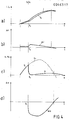
- 2c shows the difference signals ⁇ i 1 and ⁇ i 2 corresponding to the limit value violations in FIGS. 2a and 2b.
- 2d shows corresponding signals for the voltage in the event of a short-circuit in the short-circuit point K at the point in time in the forward direction V with respect to the measuring point.
- a current limit value i 0 is obtained shortly before an error occurs as a function of a fault excitation signal, for example as a function of a limit value violation of a current rise signal or a di / dt signal.
- the excitation channel is denoted by A in Fig.
- a release criterion for the direction detection can be provided in the form of limit value monitoring of ⁇ i 1 and Ai2 by means of corresponding limit switches GS1 and GS 2 and a downstream OR gate GO for enabling or blocking a sign comparison circuit CS.
- limit switches for example, only deliver an output signal via line 9 if predefinable limit values have been exceeded.
- the sign comparison circuit has, for example, an equivalence element known per se and therefore not shown in series with an enable switch. This enables closer error selection to be achieved.
- t is the time
- ⁇ is a predefinable delay time of, for example, 4 ms, preferably less than half a period of the network frequency.
- the output signal of the differential signal generator DU comes via a sign Detector in the form of a trigger TR u , for example a circuit for realizing the signal function, together with the corresponding binary signal from the trigger TR i to the evaluation circuit CS.
- This provides, for example, selective error direction signals at two outputs, each assigned to an error direction with respect to the measurement location, if the sign matches or the sign differs.
- a signal for example, at the output 5 of CS with a different sign of the signals ⁇ i and ⁇ u corresponds to a short circuit in the forward direction V with respect to the measuring point 2 in accordance with the arrow directions of i and u shown.
- a signal at the output 6 of CS with the same sign of ⁇ i and ⁇ u corresponds to a short circuit in the reverse direction, ie a short circuit in the opposite direction from V.
- a reversal of the current and voltage direction at the converters 3 and 4 has no influence on the output signals 5 and 6. If only one of these two sizes is reversed, the outputs of CS must also be exchanged.
- a simple current measuring channel I with a reference signal generator GI in the form of a delay circuit ZI is provided as a dynamic memory circuit.
- the undelayed current measurement signal i and the current measurement signal delayed in ZI are fed as the current reference signal i 0 to the subsequent difference signal generator DI.
- the delay time of ZI can be comparatively short, preferably less than a fundamental half-cycle, for example less than 3 ms, since it is essentially only a question of generating a difference signal which indicates the respective change direction of the current with its sign, namely in as soon as possible after an error occurs.
- the lower limit of the delay time is practically only that Interference level of the current measurement signal is determined, which should not impair safe sign detection.
- This version is also suitable for the continuous monitoring of the measurement signals, possibly independently of a separate fault excitation, the relevant sign information of the current or the current change occurring continuously.
- the current delay mentioned when i is formed does not constitute a detection delay because a short-circuit-related, for example sudden, change in current immediately enters the current difference signal and determines its sign.
- the voltage reference signal u can basically in the same way as in the. 1 are formed by means of delay.
- an oscillator SU which is matched to the fundamental vibration and is coupled on the input side for synchronization with the voltage measurement signal is provided for the voltage reference signal generator GU s .
- the voltage reference signal u o thus represents a continuation of the undisturbed voltage beyond the occurrence of the fault.
- the generally sudden voltage change in the event of a short circuit accordingly immediately generates a comparatively large difference signal.
- the difference signal formation gives the advantage of high signal dynamics in comparison with a detection in which signal amplitudes are used.
- the formation of the voltage reference signal using an oscillator has the particular advantage that the reference voltage, in contrast to the mere delay of the voltage measurement signal, is available for repeated direction detection even after a basic oscillation period has elapsed.
- Comparison circuit CS a separate release of the evaluation circuit as a function of the magnitude of the current difference signal is provided, specifically in the form of a magnitude comparison with predeterminable low, generally zero-point symmetrical current limit values G 1 and G 2 .
- a corresponding limit switch CD for example a Schmitt trigger, is connected to the difference signal generator DI.
- the sign evaluation is only released if the amount ⁇ i exceeds predetermined values. This avoids uncertainties in the direction detection of short circuits when ⁇ i goes through 0, cf. 4a and b.
- a control connection between the output of DU and corresponding limit value control inputs g 1 and g 2 of CD is indicated by dashed lines in FIG. 3.
- a signal converter SW which can be, for example, a hyperbola generator, is inserted into this control connection and effects a functional assignment of the limit values in accordance with the function indicated in the circuit block.
- the release can be blocked with smaller, interference-sensitive amounts of the voltage difference signal ⁇ u by increasing the amounts of the limit values G1 and G 2 .
- Limit value setting is a particularly safe release criterion for direction detection.
- the time course of the most important signals from the circuit according to FIG. 3 is shown for a short circuit in the forward direction V at time t at the short circuit point K in FIGS. 4a-d, specifically for i, u, i o , u and the corresponding difference signals ⁇ i and ⁇ u.
- the evaluation of the differential signals ⁇ i and ⁇ u and thus the detection of the fault direction can be triggered or released with a certain time delay compared to the fault occurrence detected by a particular excitation.
- the sign comparison or evaluation circuit CS is connected to the trigger channel A via a timing element Z with a corresponding blocking and release input.
- the triggers TR i and TR are indicated for the sign detection of the difference signals.
- the invention is of course not limited to what is shown in the drawings. So instead of the two subchannels of the current measuring channel, a single-channel limiter for ⁇ i o could be used.
- the triggers TR i , TR u with binary output signals circuits with 3 output states, eg "-1", "0", and "+1", can also be used, the 0 signal being present when the predefinable limit value for the current or voltage was not exceeded. Leaving the "0" state corresponds to an enabling criterion for the emission of a short-circuit direction signal.
- you can the triggers TR i and TR u can be connected to the enable input of the sign comparison circuit CS via lines 7 and 8 shown in dashed lines and the enable line 9.
Landscapes
- Physics & Mathematics (AREA)
- General Physics & Mathematics (AREA)
- Locating Faults (AREA)
- Measurement Of Current Or Voltage (AREA)
- Testing Of Short-Circuits, Discontinuities, Leakage, Or Incorrect Line Connections (AREA)
Abstract
Description
Die Erfindung bezieht sich auf ein Verfahren und eine Einrichtung zur Kurzschluss-Richtungsdetektion an elektrischen Einrichtungen, insbesondere elektrischen Leitungen und Netzen, nach dem Oberbegriff der Ansprüche 1 und 7.The invention relates to a method and a device for short-circuit direction detection on electrical devices, in particular electrical lines and networks, according to the preamble of claims 1 and 7.
Verfahren und Einrichtungen zur Kurzschluss-Richtungsdetektion mit Vorzeichen- oder Phasenwinkelvergleich von Strom- und Spannungssignalen sind allgemein bekannt (s. z.B. Leonhard Müller, Selektivschutz elektrischer Anlagen, 1971, Verlags- und Wirtschaftsgesellschaft der Elektrizitätswerke mbH., Frankfurt/Main, S. 58 ff.). Diese bekannten Verfahren arbeiten im wesentlichen mit der Grundschwingung von Strom und Spannung und erfordern daher im Hinblick auf die Ausgleichsvorgänge bei einem Kurzschluss umfangreiche Filter sowohl für den Strom- wie auch für den Spannungs-Messkanal. Eine zuverlässige Vorzeichen- bzw. Phasenwinkelauswertung der Strom- und Spannungssignale zur Fehlerrichtungsdetektion ist daher erst nach Einschwingen der Filter mit entsprechender Verzögerung möglich. Auch begrenzt die Phasenwinkelauswertung - etwa durch Auswertung von Spannungs-Nulldurchgängen - die Ansprechzeit eines Kurzschluss-Richtungsdetektors nach unten auf mindestens eine Halbperiode der Grundschwingung.Methods and devices for short-circuit direction detection with sign or phase angle comparison of current and voltage signals are generally known (see, for example, Leonhard Müller, Selective Protection of Electrical Systems, 1971, Publishing and Business Corporation of Elektrizitätswerke mbH., Frankfurt / Main, p. 58 ff.) . These known methods essentially work with the fundamental oscillation of current and voltage and therefore require extensive filters both for the current and for the voltage measurement channel with regard to the compensation processes in the event of a short circuit. A reliable sign or phase angle evaluation of the current and voltage signals for fault direction detection is therefore only possible after the filter has settled with a corresponding delay. The phase angle evaluation also limits - for example by evaluating voltage zero crossings - the response time of a short-circuit direction detector down to at least one half period of the basic oscillation.
Aufgabe der Erfindung ist es, die Zeitdauer für eine Kurzschluss-Richtungsdetektion zu verkürzen und gleichzeitig eine hohe Zuverlässigkeit der Detektion zu gewährleisten.The object of the invention is to shorten the time for a short-circuit direction detection and at the same time to ensure a high reliability of the detection.
Die Aufgabe wird gemäss den Merkmalen der Ansprüche 1 und 7 gelöst. Weiterbildungen der Erfindung sind in den Unteransprüchen beschrieben.The object is achieved according to the features of claims 1 and 7. Developments of the invention are described in the subclaims.
Ein Vorteil der Erfindung besteht darin, dass die auswertbaren Vorzeichen der Differenzsignale vergleichsweise rasch zur Verfügung stehen und damit ein schnelles und selektives Auslösen von Schutzeinrichtungen bzw. Stromabschaltungen der vom Kurzschluss betroffenen Leitungen ermöglichen.One advantage of the invention is that the evaluable signs of the differential signals are available comparatively quickly and thus enable protective devices or current cutoffs of the lines affected by the short circuit to be triggered quickly and selectively.
Weitere Merkmale und Vorteile der Erfindung werden anhand der in den Zeichnungen dargestellten Ausführungsbeispiele erläutert. Hierin zeigt:
- Fig. 1 das Prinzipschaltbild einer ersten Ausführung einer Schaltung zur Kurzschluss-Richtungsdetektion mit Strom- und Spannungs-Differenzsignalen,
- Fig. 2 ein Strom-Zeitdiagramm zur Differenzsignalbildung in der Schaltung nach Fig. 1, mit Kurzschluss bei K,
- Fig. 3 eine Abwandlung der Schaltung nach Fig. 1 mit dynamischen Speicherschaltungen im Strom- und Spannungs-Messkanal,
- Fig. 4 ein Strom- und Spannungs-Zeitdiagramm zu der Schaltung nach Fig. 3, ebenfalls mit Kurzschluss bei K, und
- Fig. 5 eine Abwandlung der Auswerteschaltung innerhalb der Schaltungsanordnung nach Fig. l.
- 1 shows the basic circuit diagram of a first embodiment of a circuit for short-circuit direction detection with current and voltage difference signals,
- 2 shows a current-time diagram for the formation of a differential signal in the circuit according to FIG. 1, with a short circuit at K,
- 3 shows a modification of the circuit according to FIG. 1 with dynamic memory circuits in the current and voltage measuring channel,
- Fig. 4 is a current and voltage timing diagram for the circuit of FIG. 3, also with a short circuit at K, and
- 5 shows a modification of the evaluation circuit within the circuit arrangement according to FIG.
Gemäss Fig. 1 ist in einer auf einen Kurzschluss zu überwachenden,Stromversorgungsleitung 1 eine Messstelle 2 mit einem Stromwandler 3 und einem Spannungswandler 4 vorgesehen. K bezeichnet einen Kurzschluss in einer vorgebbaren Vorwärtsrichtung V der Leitung 1. Das von dem Stromwandler 3 abgeleitete und dem Strom in der Leitung 1 proportionale Strom-Messsignal i wird einem Strom-Messkanal mit zwei Teilkanälen I1 und I2 für die beiden Halbschwingungen entgegengesetzten Vorzeichens zugeführt. Das von dem Spannungswandler 4 abgeleitete und der Spannung in der Leitung 1 proportionale Spannungs-Messsignal u wird einem Spannungs-Messkanal U zugeführt. In den beiden Teilkanälen I1 und I2 ist je ein Differenzsignalbildner DI1 bzw. DI2 angeordnet, der aus der betreffenden Halbschwingung des Strom-Messsignals i einerseits und Strom-Mess- signalenil bzw. i2 andererseits, die auf einen vorgebbaren Strom-Grenzwert bzw. auf ein Strom-Bezugssignal +io bzw. -io begrenzt sind, ein Strom-Differenzsignal Δ i1 bzw. Δ i2 bildet. Diese beiden, den Halbschwingungen des Stromes zugeordneten Strom-Differenzsignale Δ i1 und Δ i2 werden einem Vorzeichendetektor üblicher Art, z.B. einem bistabilen Vibrator (Flipflop) bzw. einem bipolaren Trigger TR1 zugeführt, der ausgangsseitig ein binäres Signal entsprechend dem jeweiligen Vorzeichen des Strom-Differenzsignals liefert. Die Bezugs-Strom-Messsignale il bzw. i2 werden in den Teilkanälen I1 und I2 mittels Bezugssignalgebern GI1 bzw. GI2 gebildet, die als Messwert-Begrenzer ausgebildet sind. Für das Ausgangssignal i1 von GI1 gilt:![]()
![]()
![]()
![]()
![]()
![]()
![]()
![]()
Wie aus Fig. 2 hervorgeht, bleibt das Ausgangssignal der Differenzbildner DI1 (Fig. 2a) bzw. DI2 (Fig. 2b) Null, solange +io bzw. -io durch i nicht über- bzw. unterschritten wird. Der Betrag des Strom-Grenzwertes io stellt also einen Grenzwert dar, der einem Ueberstrom-Anregekriterium entspricht. Fig. 2c zeigt die den Grenzwertüberschreitungen in Fig. 2a und 2b entsprechenden Differenzsignale Δ i1 und Δ i2. Fig. 2d zeigt entsprechende Signale für die Spannung bei einem Kurzschluss in der Kurzschlussstelle K im Zeitpunkt to in Vorwärtsrichtung V bezüglich der Messstelle.As can be seen from FIG. 2, the output signal of the difference formers DI 1 (FIG. 2a) and DI 2 (FIG. 2b) remains zero as long as + i o or -i o is not exceeded or undershot by i. The amount of the current limit value i o thus represents a limit value which corresponds to an overcurrent excitation criterion. 2c shows the difference signals Δ i 1 and Δ i 2 corresponding to the limit value violations in FIGS. 2a and 2b. 2d shows corresponding signals for the voltage in the event of a short-circuit in the short-circuit point K at the point in time in the forward direction V with respect to the measuring point.
Grundsätzlich kann auch mit einer anderen Anregung des Kurzschluss-Richtungsdetektors gearbeitet und ein entsprechendes Stromsignal vor Fehlereintritt oder bei einem ersten Anzeichen für einen Kurzschluss als Bezugssignal io verwendet sowie gespeichert werden. i0 ist dann keine Konstante, sondern eine Funktion des Strommesssignals i . Eine solche Variante ist in Fig. 1 gestrichelt angedeutet. Die Gewinnung eines Strom-Grenzwertes i0 erfolgt dabei kurz vor Fehlereintritt in Abhängigkeit von einem Fehler-Anregesignal, z.B. in Abhängigkeit von einer Grenzwertüberschreitung eines Stromanstiegs- bzw. eines di/dt-Signals. Der Anregekanal ist in Fig. 1 mit A bezeichnet, während die zugehörigen Abtast- und Speicherschaltungen an sich üblicher Art (vgl. z.B. DE-PS 2 406 196) mit SH bezeichnet sind. Letztere liefern wiederum die Werte +io und -io für das Stromgrenzwertsignal, jedoch nun nicht mehr als fest vorgegebene Strom-Grenzwerte, sondern als Augenblickswerte des Strom-Messsignals kurz vor oder bei Fehlereintritt. Die anschliessende Signalverarbeitung und Auswertung unterscheidet sich nicht von der ersten Variante, jedoch wird eine bessere Anpassung der Richtungsdetektion an die jeweiligen Kurzschlussverhältnisse im Vergleich zu starren Strom-Grenzwerten erreicht.In principle, it is also possible to work with another excitation of the short-circuit direction detector and to use and store a corresponding current signal before the occurrence of an error or at the first sign of a short-circuit as a reference signal i o . i 0 is then not a constant, but a function of the current measurement signal i. Such a variant is indicated by dashed lines in FIG. 1. A current limit value i 0 is obtained shortly before an error occurs as a function of a fault excitation signal, for example as a function of a limit value violation of a current rise signal or a di / dt signal. The excitation channel is denoted by A in Fig. 1, while the associated sampling and storage circuits in a conventional manner (see, for example,
Zusätzlich kann , wie in Fig. 1 angedeutet, ein Freigabekriterium für die Richtungsdetektion in Form einer Grenzwertüberwachung von Δi1 und Ai2 mittels entsprechender Grenzwertschalter GS1 und GS2 und eines nachgeschalteten ODER-Gliedes GO zur Freigabe bzw. Sperrung einer Vorzeichenvergleichsschaltung CS vorgesehen werden. Diese Grenzwertschalter liefern z.B. nur dann ein Ausgangssignal über die Leitung 9 wenn vorgebbare Grenzwerte überschritten sind. Die Vorzeichenvergleichsschaltung weist z.B. ein an sich bekanntes und deshalb nicht dargestelltes Aequivalenzglied in Reihe mit einem Freigabeschalter auf. Damit lässt sich eine engere Fehlerselektion erreichen.In addition, as indicated in FIG. 1, a release criterion for the direction detection can be provided in the form of limit value monitoring of Δi 1 and Ai2 by means of corresponding limit switches GS1 and GS 2 and a downstream OR gate GO for enabling or blocking a sign comparison circuit CS. These limit switches, for example, only deliver an output signal via
Die Schaltung nach Fig. 1 umfasst ferner innerhalb des Spannungs-Messkanals U einen Bezugssignalgeber GU mit einer Verzögerungsschaltung ZU für die Bildung eines Spannungs-Bezugssignals uo = u(t-τ) für die anschliessende Erzeugung eines Spannungs-Differenzsignals Δ u = u - u in einem entsprechenden Differenzbildner DU. Dabei bedeuten t die Zeit und τ eine vorgebbare Verzögerungszeitdauer von z.B. 4 ms, vorzugsweise von weniger als einer halben Periodendauer der Netzfrequenz. Das Ausgangssignal des Differenzsignalbildners DU gelangt über einen Vorzeichendetektor in Form eines Triggers TRu, z.B. einer Schaltung zur Realisierung der Signumfunktion, zusammen mit dem entsprechenden binären Signal vom Trigger TRi zur Auswerteschaltung CS. Diese liefert z.B. an zwei je einer Fehlerrichtung bezüglich des Messortes zugeordneten Ausgängen bei Vorzeichenübereinstimmung bzw. Vorzeichenverschiedenheit selektive Fehlerrichtungssignale. Ein Signal z.B am Ausgang 5 von CS bei unterschiedlichem Vorzeichen der Signale Δ i und Δ u entspricht einem Kurzschluss in Vorwärtsrichtung V bezüglich der Messstelle 2 entsprechend den eingezeichneten Pfeilrichtungen von i und u. Ein Signal am Ausgang 6 von CS bei gleichem Vorzeichen von Δ i und Δ u entspricht einem Kurzschluss in Rückwärtsrichtung, d.h. einem Kurzschluss in Gegenrichtung von V. Eine Umkehrung der Strom- und Spannungsrichtung an den Wandlern 3 und 4 hat keinen Einfluss auf die Ausgangssignale 5 und 6. Wird nur eine dieser beiden Grössen umgepolt, so sind auch die Ausgänge von CS zu vertauschen.The circuit according to FIG. 1 further comprises a reference signal generator GU within the voltage measurement channel U with a delay circuit ZU for forming a voltage reference signal u o = u (t-τ) for the subsequent generation of a voltage difference signal Δ u = u - u in a corresponding difference former DU. Here, t is the time and τ is a predefinable delay time of, for example, 4 ms, preferably less than half a period of the network frequency. The output signal of the differential signal generator DU comes via a sign Detector in the form of a trigger TR u , for example a circuit for realizing the signal function, together with the corresponding binary signal from the trigger TR i to the evaluation circuit CS. This provides, for example, selective error direction signals at two outputs, each assigned to an error direction with respect to the measurement location, if the sign matches or the sign differs. A signal, for example, at the
Bei der Schaltung nach Fig. 3 ist nur ein einfacher Strom-Messkanal I mit einem Bezugssignalgeber GI in Form einer Verzögerungsschaltung ZI als dynamische Speicherschaltung vorgesehen. Dem nachfolgenden Differenzsignalbildner DI wird das unverzögerte Strom-Messsignal i und das in ZI verzögerte Strom-Messsignal als Strom-Bezugssignal i0 zugeführt. Die Verzögerungszeit von ZI kann vergleichsweise gering bemessen sein, vorzugsweise geringer als eine Grundschwingungs-Halbperiode, zum Beispiel unter 3 ms, da es im wesentlichen nur auf die Erzeugung eines Differenzsignals ankommt, das mit seinem Vorzeichen die jeweilige Aenderungsrichtung des Stromes anzeigt, und zwar in möglichstkurzer Zeit nach Fehlereintritt. Die untere Grenze der Verzögerungszeit ist dabei praktisch nur durch den Störpegel des Strom-Messsignals bestimmt, der eine sichere Vorzeichendetektion nicht beeinträchtigen soll. Diese Ausführung eignet sich auch für eine laufende Ueberwachung der Messsignale, gegebenenfalls unabhängig von einer gesonderten Fehleranregung, wobei laufend die relevante Vorzeicheninformation des Stromes bzw. der Stromänderung anfällt. Die genannte Stromverzögerung bei der Bildung von i stellt übrigens keine Detektionsverzögerung dar, weil eine kurzschlussbedingte, z.B. sprungartige Stromänderung sofort in das Strom-Differenzsignal eingeht und dessen Vorzeichen bestimmt.In the circuit according to FIG. 3, only a simple current measuring channel I with a reference signal generator GI in the form of a delay circuit ZI is provided as a dynamic memory circuit. The undelayed current measurement signal i and the current measurement signal delayed in ZI are fed as the current reference signal i 0 to the subsequent difference signal generator DI. The delay time of ZI can be comparatively short, preferably less than a fundamental half-cycle, for example less than 3 ms, since it is essentially only a question of generating a difference signal which indicates the respective change direction of the current with its sign, namely in as soon as possible after an error occurs. The lower limit of the delay time is practically only that Interference level of the current measurement signal is determined, which should not impair safe sign detection. This version is also suitable for the continuous monitoring of the measurement signals, possibly independently of a separate fault excitation, the relevant sign information of the current or the current change occurring continuously. Incidentally, the current delay mentioned when i is formed does not constitute a detection delay because a short-circuit-related, for example sudden, change in current immediately enters the current difference signal and determines its sign.
Das Spannungs-Bezugssignal u kann grundsätzlich in gleicher Weise wie bei der. Schaltung nach Fig. 1 mittels Verzögerung gebildet werden. Im Beispiel nach Fig. 3 ist für den Spannungs-Bezugssignalgeber GUs ein auf die GrundSchwingung abgestimmter und eingangsseitig zur Synchronisierung mit dem Spannungs-Messsignal gekoppelter Oszillator SU vorgesehen. Das Spannungs-Bezugssignal uo stellt hier also eine Fortsetzung der ungestörten Spannung über den Fehlereintritt hinaus dar. Die im allgemeinen sprungartige Spannungsänderung beim Kurzschluss erzeugt demgemäss sofort ein vergleichsweise grosses Differenzsignal. Für den Strom- und Spannungs-Messkanal ergibt die Differenzsignalbildung den Vorteil einer hohen Signaldynamik im Vergleich mit einer Detektion, bei der Signalamplituden verwendet werden. Die Bildung des Spannungs-Bezugssignals unter Verwendung eines Oszillators hat dabei den besonderen Vorteil, dass die Bezugsspannung, im Unterschied zur blossen Verzögerung des, Spannungs-Messsignals, für eine wiederholte Richtungsdetektion auch nach Ablauf einer Grundschwingungs-Periodendauer verfügbar ist.The voltage reference signal u can basically in the same way as in the. 1 are formed by means of delay. In the example according to FIG. 3, an oscillator SU which is matched to the fundamental vibration and is coupled on the input side for synchronization with the voltage measurement signal is provided for the voltage reference signal generator GU s . The voltage reference signal u o thus represents a continuation of the undisturbed voltage beyond the occurrence of the fault. The generally sudden voltage change in the event of a short circuit accordingly immediately generates a comparatively large difference signal. For the current and voltage measurement channel, the difference signal formation gives the advantage of high signal dynamics in comparison with a detection in which signal amplitudes are used. The formation of the voltage reference signal using an oscillator has the particular advantage that the reference voltage, in contrast to the mere delay of the voltage measurement signal, is available for repeated direction detection even after a basic oscillation period has elapsed.
Die Auswertung erfolgt wieder in einer Vorzeichen-The evaluation takes place again in a sign
Vergleichsschaltung CS. Auch hier ist eine gesonderte Freigabe der Auswerteschaltung in Abhängigkeit von dem Betrag des Strom-Differenzsignals vorgesehen, und zwar in Form eines Betragsvergleichs mit vorgebbaren niedrigen,im allgemeinen nullpunkt-symmetrischen Strom-Grenzwerten G1 und G2. Hierfür ist an die Differenzsignalbildner DI ein entsprechender Grenzwertschalter CD, z.B. ein Schmitt-Trigger,angeschlossen.Comparison circuit CS. Here too, a separate release of the evaluation circuit as a function of the magnitude of the current difference signal is provided, specifically in the form of a magnitude comparison with predeterminable low, generally zero-point symmetrical current limit values G 1 and G 2 . For this purpose, a corresponding limit switch CD, for example a Schmitt trigger, is connected to the difference signal generator DI.
Auf diese Weise wird die Vorzeichenauswertung nur dann freigegeben wenn der Betrag Δ i vorgegebene Werte überschreitet. Damit vermeidet man Unsicherheiten bei der Richtungsdetektion von Kurzschlüssen, wenn Δ i durch 0 geht, vgl. Fig. 4a und b.In this way, the sign evaluation is only released if the amount Δ i exceeds predetermined values. This avoids uncertainties in the direction detection of short circuits when Δ i goes through 0, cf. 4a and b.
Man kann gegebenenfalls alle Unsicherheits- und Umkehrungsbereiche ausschliessen, indem man die Stromdifferenz-Grenzwerte G1 und G2 vom Betrage des Spannungsdifferenzsignals Δ u in gegensinniger Weise abhängig gemacht, d.h je kleinere u ist, desto grösser werden die Grenzwerte Gl und G2 gewählt. Hierzu ist eine Steuerverbindung zwischen dem Ausgang von DU und entsprechenden Grenzwert-Steuereingängen g1 und g2 von CD in Fig. 3 strichliert angedeutet. In diese Steuerverbindung ist ein Signalwandler SW, der z.B. ein Hyperbelgenerator sein kann, eingefügt, der eine funktionale Zuordnung der Grenzwerte entsprechend der im Schaltungsblock angedeuteten Funktion bewirkt. Dadurch kann, zum Beispiel, eine Blockierung der Freigabe bei kleineren, störempfindlichen Beträgen des Spannungs-Differenzsignals Δ u durch Heraufsetzen der Beträge der Grenzwerte G1 und G2 erzielt werden. Nachdem sich Strom und Spannung bei einem Kurzschluss in Vorwärtsrichtung zueinander gegensinnig ändern, ermöglicht diese Grenzwerteinstellung ein besonders sicheres Freigabekriterium für die Richtungsdetektion.If necessary, all areas of uncertainty and inversion can be excluded by making the current difference limit values G 1 and G 2 dependent on the magnitude of the voltage difference signal Δ u in opposite directions, ie the smaller u is, the larger the limit values Gl and G2 are chosen. For this purpose, a control connection between the output of DU and corresponding limit value control inputs g 1 and g 2 of CD is indicated by dashed lines in FIG. 3. A signal converter SW, which can be, for example, a hyperbola generator, is inserted into this control connection and effects a functional assignment of the limit values in accordance with the function indicated in the circuit block. In this way, for example, the release can be blocked with smaller, interference-sensitive amounts of the voltage difference signal Δ u by increasing the amounts of the limit values G1 and G 2 . After current and voltage change in opposite directions to each other in the event of a short circuit in the forward direction, this enables Limit value setting is a particularly safe release criterion for direction detection.
Der Zeitverlauf der wichtigsten Signale aus der Schaltung nach Fig. 3 ist für einen Kurzschluss in Vorwärtsrichtung V zum Zeitpunkt t an der Kurzschlussstelle K in den Fig. 4a - d wiedergegeben, und zwar für i, u, io, u und die entsprechenden Differenzsignale Δ i und Δ u.The time course of the most important signals from the circuit according to FIG. 3 is shown for a short circuit in the forward direction V at time t at the short circuit point K in FIGS. 4a-d, specifically for i, u, i o , u and the corresponding difference signals Δ i and Δ u.
Weiterhin kann gemäss der in Fig. 5 angedeuteten Schaltungsvariante die Auswertung der Differenzsignale Δ i und Δ u und damit die Fehlerrichtungsdetektion mit einer bestimmten Zeitverzögerung gegenüber dem durch eine besondere Anregung detektierten Fehlereintritt ausgelöst bzw. freigegeben werden. Hierzu ist die Vorzeichen-Vergleichs- bzw. Auswertschaltung CS mit einem entsprechenden Sperr- und Freigabeeingang über ein Zeitglied Z an den Auslösekanal A angeschlossen. Von der übrigen Schaltung, die mit der Ausführung nach Fig. 1 oder Fig. 3 übereinstimmen kann, sind nur die Trigger TRi und TR für die Vorzeichendetektion der Differenzsignale angedeutet.Furthermore, according to the circuit variant indicated in FIG. 5, the evaluation of the differential signals Δ i and Δ u and thus the detection of the fault direction can be triggered or released with a certain time delay compared to the fault occurrence detected by a particular excitation. For this purpose, the sign comparison or evaluation circuit CS is connected to the trigger channel A via a timing element Z with a corresponding blocking and release input. Of the rest of the circuit, which can correspond to the embodiment according to FIG. 1 or FIG. 3, only the triggers TR i and TR are indicated for the sign detection of the difference signals.
Die Erfindung ist auf das in den Zeichnungen Dargestellte selbstverständlich nicht beschränkt. So könnte anstelle der beiden Teilkanäle des Strommesskanals ein einkanaliger Begrenzer für ± io verwendet werden. Anstelle der Trigger TRi, TRu mit binären Ausgangssignalen können auch Schaltungen mit 3 Ausgangszüständen, z.B. "-1", "0", und "+1", verwendet werden, wobei das 0-Signal dann anliegt, wenn der vorgebbare Grenzwert für den Strom bzw. die Spannung nicht überschritten wurde. Das Verlassen des Zustandes "0" entspricht einem Freigabekriterium für die Abgabe eines Kurzschluss-Richtungssignals. Zu diesem Zweck können die Trigger TRi bzw. TRu über gestrichelt gezeichnete Leitungen 7 bzw. 8 und die Freigabeleitung 9 mit dem Freigabeeingang der Vorzeichenvergleichsschaltung CS verbunden sein.The invention is of course not limited to what is shown in the drawings. So instead of the two subchannels of the current measuring channel, a single-channel limiter for ± i o could be used. Instead of the triggers TR i , TR u with binary output signals, circuits with 3 output states, eg "-1", "0", and "+1", can also be used, the 0 signal being present when the predefinable limit value for the current or voltage was not exceeded. Leaving the "0" state corresponds to an enabling criterion for the emission of a short-circuit direction signal. For this purpose you can the triggers TR i and TR u can be connected to the enable input of the sign comparison circuit CS via
- A AnregekanalA excitation channel
- CD GrenzwertschalterCD limit switch
- CS Vorzeichen-VergleichsschalterCS sign comparison switch
- DI1, DI2 DifferenzsignalbildnerDI 1 , DI2 difference signal generator
- DI, DU DifferenzsignalbildnerDI, DU difference signal generator
- G1, G2 StromgrenzwertG 1 , G 2 current limit
- GU BezugssignalgeberGU reference signal transmitter
- I1, I2 Teilkanäle des StrommesskanalsI 1 , I 2 subchannels of the current measuring channel
- +io, -io Stromgrenzwerte bzw. Strom-Bezugssignale+ i o , -i o Current limit values or current reference signals
- Δ i1, Δ i2 StromdifferenzsignaleΔ i 1 , Δ i 2 current difference signals
- i Strommesssignali Current measurement signal
- ii, i2 Ausgangssignal von GI1 bzw. GI2 i i , i 2 output signal from GI 1 or GI 2
- τ Verzögerungszeitdauer bzw. Zeitverzögerungτ delay period or time delay
- K KurzschlussstelleK short circuit
- SH Abtast- und SpeicherschaltungSH sampling and storage circuit
- SU OszillatorSU oscillator
- SW SignalwandlerSW signal converter
- t Zeitt time
- to Zeitpunkt des Fehlereintrittst o time of error
- TRi Trigger bistabiler Vibrator (Flipflop).TR i trigger bistable vibrator (flip-flop).
- u . Spannungs-Messsignalu. Voltage measurement signal
- U Spannungs-MesskanalU voltage measuring channel
- Uo Spannungs-BezugssignalU o voltage reference signal
- V Vorwärtsrichtung der LeitungV Forward direction of the line
- ZU Verzögerungsschaltung bzw. ZeitverzögerungCLOSE delay circuit or time delay
- 1 elektrische Leitung1 electrical line
- 2 Messstelle2 measuring point
- 3 Stromwandler3 current transformers
- 4 Spannungswandler4 voltage transformers
- 5 Ausgangssignal von CS für Kurzschluss in Vorwärtsrichtung5 Output signal from CS for short circuit in the forward direction
- 6 Ausgangssignal von CS für Kurzschluss in Rückwärtsrichtung6 Output signal from CS for short circuit in the reverse direction
- 7, 8 Leitungen7, 8 lines
- 9 Freigabeleitung9 Release line
Claims (12)
dadurch gekennzeichnet, dass
characterized in that
in seinem.Zeitverlauf dem vor dem Kurzschluss vorhandenen Spannungsmesssignal (u) im Zeitverlauf entspricht und über den Fehlereintritt (t ) hinaus vorhanden ist.6. A method for short-circuit direction detection according to claims 1 to 3, characterized in that a voltage reference signal (u) is used, the
its time course corresponds to the voltage measurement signal (u) present before the short circuit over time and is present beyond the occurrence of the fault (t).
dadurch gekennzeichnet, dass
characterized in that
Applications Claiming Priority (2)
| Application Number | Priority Date | Filing Date | Title |
|---|---|---|---|
| CH6167/80 | 1980-08-15 | ||
| CH616780 | 1980-08-15 |
Publications (2)
| Publication Number | Publication Date |
|---|---|
| EP0046317A1 true EP0046317A1 (en) | 1982-02-24 |
| EP0046317B1 EP0046317B1 (en) | 1985-01-30 |
Family
ID=4305322
Family Applications (1)
| Application Number | Title | Priority Date | Filing Date |
|---|---|---|---|
| EP19810200845 Expired EP0046317B1 (en) | 1980-08-15 | 1981-07-23 | Process and arrangement for detecting the direction of a short circuit |
Country Status (3)
| Country | Link |
|---|---|
| EP (1) | EP0046317B1 (en) |
| JP (1) | JPS5754873A (en) |
| DE (1) | DE3168624D1 (en) |
Cited By (3)
| Publication number | Priority date | Publication date | Assignee | Title |
|---|---|---|---|---|
| EP0098624A1 (en) * | 1982-06-23 | 1984-01-18 | BBC Aktiengesellschaft Brown, Boveri & Cie. | Process for detecting faults or fault direction in electrical lines and means for carrying it out |
| FR2538122A1 (en) * | 1982-12-16 | 1984-06-22 | Enertec | Improvement to methods and devices for determining a parameter associated with a faulty electric line |
| CN111796164A (en) * | 2020-07-16 | 2020-10-20 | 西南交通大学 | Fault location method for full-parallel AT traction network |
Families Citing this family (2)
| Publication number | Priority date | Publication date | Assignee | Title |
|---|---|---|---|---|
| JPH073450B2 (en) * | 1984-02-22 | 1995-01-18 | 財団法人鉄道総合技術研究所 | Fault location method for DC electric railway feeder circuit |
| JPH0654339B2 (en) * | 1985-07-04 | 1994-07-20 | 日立電線株式会社 | Failure direction orientation method |
Citations (2)
| Publication number | Priority date | Publication date | Assignee | Title |
|---|---|---|---|---|
| FR2380631A1 (en) * | 1977-02-09 | 1978-09-08 | Schlumberger Compteurs | DIRECTIONAL RELAY |
| US4187461A (en) * | 1978-02-21 | 1980-02-05 | Dranetz Engineering Laboratories, Inc. | Dynamic threshold impulse directivity indicator |
-
1981
- 1981-07-23 DE DE8181200845T patent/DE3168624D1/en not_active Expired
- 1981-07-23 EP EP19810200845 patent/EP0046317B1/en not_active Expired
- 1981-08-13 JP JP12605881A patent/JPS5754873A/en active Pending
Patent Citations (2)
| Publication number | Priority date | Publication date | Assignee | Title |
|---|---|---|---|---|
| FR2380631A1 (en) * | 1977-02-09 | 1978-09-08 | Schlumberger Compteurs | DIRECTIONAL RELAY |
| US4187461A (en) * | 1978-02-21 | 1980-02-05 | Dranetz Engineering Laboratories, Inc. | Dynamic threshold impulse directivity indicator |
Non-Patent Citations (2)
| Title |
|---|
| ASEA Journal, Band 45, Nr. 3, 1972, seiten 87-90 Vasteras, SE. C.-H. EINVALL: "Directional Relay type RXPE 4" * Abschnitt "Operating time" und figur 8 auf seite 90 * * |
| IEE Proceedings-C, Band 127, Nr. 4, Juli 1980, seiten 228-239 Stevenage, G.B. A.T. JOHNS: "New Ultra-High-Speed Directional Comparison Technique for the Protection of e.h.v. Transmission lines" * seite 238, Abschnitt "6 Conclusions", erster Absatz - figur 6a auf seit 234 * * |
Cited By (4)
| Publication number | Priority date | Publication date | Assignee | Title |
|---|---|---|---|---|
| EP0098624A1 (en) * | 1982-06-23 | 1984-01-18 | BBC Aktiengesellschaft Brown, Boveri & Cie. | Process for detecting faults or fault direction in electrical lines and means for carrying it out |
| FR2538122A1 (en) * | 1982-12-16 | 1984-06-22 | Enertec | Improvement to methods and devices for determining a parameter associated with a faulty electric line |
| CN111796164A (en) * | 2020-07-16 | 2020-10-20 | 西南交通大学 | Fault location method for full-parallel AT traction network |
| CN111796164B (en) * | 2020-07-16 | 2021-04-13 | 西南交通大学 | Fault location method for full-parallel AT traction network |
Also Published As
| Publication number | Publication date |
|---|---|
| EP0046317B1 (en) | 1985-01-30 |
| JPS5754873A (en) | 1982-04-01 |
| DE3168624D1 (en) | 1985-03-14 |
Similar Documents
| Publication | Publication Date | Title |
|---|---|---|
| EP0127139B1 (en) | Supply-voltage monitoring circuit | |
| DE2529898C3 (en) | Device for localizing the fault location on a line | |
| DE2221048C2 (en) | Arrangement for the determination of time intervals in which the measuring signal of a measuring transformer is faulty due to its saturation state | |
| DE2838549A1 (en) | PULSE WIDTH MEASUREMENT | |
| DE2338882A1 (en) | PROCEDURE AND REMOTE CONTROL SYSTEM FOR SWITCHING ELECTRICAL CONSUMERS ON AND OFF | |
| DE2952156C2 (en) | ||
| EP0046317B1 (en) | Process and arrangement for detecting the direction of a short circuit | |
| DE2545325B2 (en) | Circuit arrangement for measuring the insulation resistance of floating power circuits | |
| DE2243742A1 (en) | DEVICE FOR DIGITAL CONTROL OF THE SIZE OF THE MACHINING GAP IN A SPARK EDM MACHINING PROCESS | |
| EP0098624A1 (en) | Process for detecting faults or fault direction in electrical lines and means for carrying it out | |
| CH623963A5 (en) | ||
| DE3016108A1 (en) | VOLTAGE MEASURING | |
| DE3836811C2 (en) | ||
| EP0134001B1 (en) | Electronic electric-energy meter with automatic offset regulation | |
| DE3245008C2 (en) | ||
| EP1071961B1 (en) | Layout, method and current measuring device for measuring a current in a conductor | |
| DE2621071A1 (en) | PENDULUM PROTECTION RELAY | |
| DE2144537C3 (en) | Signaling system | |
| EP0015226B1 (en) | Circuitry for memorizing the phase position of an alternating voltage | |
| DE1132589B (en) | Switchable blocking circuit for generating an output power, the polarity of which depends on the polarity of the input power | |
| EP0122473A1 (en) | Method of monitoring the charging of batteries | |
| DE2842350C2 (en) | Circuit arrangement for monitoring clock pulse trains | |
| DE2725618C3 (en) | Device for measuring the integral of a time-dependent physical quantity | |
| DE3346527A1 (en) | METHOD AND ARRANGEMENT FOR THE FAULT-SAFE ALARM EVALUATION OF A DETECTING LINE OF A DANGER DETECTING SYSTEM | |
| DE3124073C2 (en) | Method and arrangement for performing the method for digitally monitoring defined current states or voltage drops proportional to them |
Legal Events
| Date | Code | Title | Description |
|---|---|---|---|
| PUAI | Public reference made under article 153(3) epc to a published international application that has entered the european phase |
Free format text: ORIGINAL CODE: 0009012 |
|
| AK | Designated contracting states |
Designated state(s): CH DE SE |
|
| 17P | Request for examination filed |
Effective date: 19820319 |
|
| GRAA | (expected) grant |
Free format text: ORIGINAL CODE: 0009210 |
|
| AK | Designated contracting states |
Designated state(s): CH DE LI SE |
|
| REF | Corresponds to: |
Ref document number: 3168624 Country of ref document: DE Date of ref document: 19850314 |
|
| PLBE | No opposition filed within time limit |
Free format text: ORIGINAL CODE: 0009261 |
|
| STAA | Information on the status of an ep patent application or granted ep patent |
Free format text: STATUS: NO OPPOSITION FILED WITHIN TIME LIMIT |
|
| 26N | No opposition filed | ||
| PGFP | Annual fee paid to national office [announced via postgrant information from national office to epo] |
Ref country code: SE Payment date: 19890619 Year of fee payment: 9 |
|
| PGFP | Annual fee paid to national office [announced via postgrant information from national office to epo] |
Ref country code: DE Payment date: 19890925 Year of fee payment: 9 |
|
| PGFP | Annual fee paid to national office [announced via postgrant information from national office to epo] |
Ref country code: CH Payment date: 19891024 Year of fee payment: 9 |
|
| PG25 | Lapsed in a contracting state [announced via postgrant information from national office to epo] |
Ref country code: SE Effective date: 19900724 |
|
| PG25 | Lapsed in a contracting state [announced via postgrant information from national office to epo] |
Ref country code: LI Effective date: 19900731 Ref country code: CH Effective date: 19900731 |
|
| REG | Reference to a national code |
Ref country code: CH Ref legal event code: PL |
|
| PG25 | Lapsed in a contracting state [announced via postgrant information from national office to epo] |
Ref country code: DE Effective date: 19910403 |
|
| EUG | Se: european patent has lapsed |
Ref document number: 81200845.6 Effective date: 19910402 |