EP0042255A1 - Method and apparatus for nuclear magnetic resonance - Google Patents
Method and apparatus for nuclear magnetic resonance Download PDFInfo
- Publication number
- EP0042255A1 EP0042255A1 EP81302589A EP81302589A EP0042255A1 EP 0042255 A1 EP0042255 A1 EP 0042255A1 EP 81302589 A EP81302589 A EP 81302589A EP 81302589 A EP81302589 A EP 81302589A EP 0042255 A1 EP0042255 A1 EP 0042255A1
- Authority
- EP
- European Patent Office
- Prior art keywords
- magnetic field
- magnetic resonance
- nuclear magnetic
- nmr
- generating
- Prior art date
- Legal status (The legal status is an assumption and is not a legal conclusion. Google has not performed a legal analysis and makes no representation as to the accuracy of the status listed.)
- Granted
Links
Images


Classifications
-
- G—PHYSICS
- G01—MEASURING; TESTING
- G01R—MEASURING ELECTRIC VARIABLES; MEASURING MAGNETIC VARIABLES
- G01R33/00—Arrangements or instruments for measuring magnetic variables
- G01R33/20—Arrangements or instruments for measuring magnetic variables involving magnetic resonance
- G01R33/44—Arrangements or instruments for measuring magnetic variables involving magnetic resonance using nuclear magnetic resonance [NMR]
- G01R33/48—NMR imaging systems
- G01R33/54—Signal processing systems, e.g. using pulse sequences ; Generation or control of pulse sequences; Operator console
- G01R33/56—Image enhancement or correction, e.g. subtraction or averaging techniques, e.g. improvement of signal-to-noise ratio and resolution
- G01R33/563—Image enhancement or correction, e.g. subtraction or averaging techniques, e.g. improvement of signal-to-noise ratio and resolution of moving material, e.g. flow contrast angiography
- G01R33/56375—Intentional motion of the sample during MR, e.g. moving table imaging
- G01R33/56383—Intentional motion of the sample during MR, e.g. moving table imaging involving motion of the sample as a whole, e.g. multistation MR or MR with continuous table motion
-
- G—PHYSICS
- G01—MEASURING; TESTING
- G01N—INVESTIGATING OR ANALYSING MATERIALS BY DETERMINING THEIR CHEMICAL OR PHYSICAL PROPERTIES
- G01N24/00—Investigating or analyzing materials by the use of nuclear magnetic resonance, electron paramagnetic resonance or other spin effects
- G01N24/08—Investigating or analyzing materials by the use of nuclear magnetic resonance, electron paramagnetic resonance or other spin effects by using nuclear magnetic resonance
-
- G—PHYSICS
- G01—MEASURING; TESTING
- G01R—MEASURING ELECTRIC VARIABLES; MEASURING MAGNETIC VARIABLES
- G01R33/00—Arrangements or instruments for measuring magnetic variables
- G01R33/20—Arrangements or instruments for measuring magnetic variables involving magnetic resonance
- G01R33/28—Details of apparatus provided for in groups G01R33/44 - G01R33/64
- G01R33/38—Systems for generation, homogenisation or stabilisation of the main or gradient magnetic field
- G01R33/3806—Open magnet assemblies for improved access to the sample, e.g. C-type or U-type magnets
Definitions
- This invention relates to a nuclear magnetic resonance apparatus for measuring from outside of a body both the distribution of a specific atomic nucleus in the body to be examined and the relaxation time of the atomic nucleus by making use of the nuclear magnetic resonance (NMR) phenomena.
- NMR nuclear magnetic resonance
- the prior art apparatus measure mainly the physical properties of a human body. More specifically, X-ray apparatus discriminates between human tissues and defines their shapes in accordance with the differences in the X-ray transmission characteristics among the human tissues so that a variety of diseases or conditions can be identified. On the other hand, ultrasonic apparatus finds the differences in acoustic impedance among the human tissues thereby to discriminate between tissues and to measure their shapes and motions.
- the nuclear medical apparatus measures the distribution of a radioactive isotope, or.its compound, with which a human body has been dosed, and is thereby able to distinguish among the human tissues and to some extent determine the conditions of the respective tissues. Therefore, the nuclear medical apparatus aims mainly at gathering macroscopic information as to each tissue although it can obtain biological information to some extent.
- X-ray apparatus especially has the disadvantage of the exposure of the tissues of the body to X-rays from the outside of the body, and the nuclear medical apparatus has the disadvantage of the exposure of the tissues of the body to Y -rays from the inside of the body.
- Atomic nuclei are composed of protons and neutrons.
- the protons and neutrons spin as a whole like a top, having a nuclear spin angular momentum denominated I.
- the atomic nucleus ( 1 H ) of hydrogen is composed of a single proton having a spin expressed by a spin quantum number of 1/2, as shown in Figure la.
- the proton P has a positive electric charge e + , as shown in Figure lb, the phenomenon has the same electrical result as that produced when a current corresponding to the positive charge flow through a small coil in accordance with the spins of the nucleus so that a magnetic momentum is established.
- each hydrogen nucleus can be regarded as a small magnet.
- electromagnetic waves which are usually radio-frequency waves
- the relaxation time is a time constant dependent upon the manner of combination of individual chemical compounds and is known to be very different for normal tissues and malignant tissues.
- the foregoing description has been directed to the atomic nucleus ( l g) of hydrogen
- other atomic nuclei having different nuclear spin angular momentumes can be used to perform similar-measurements.
- the atomic nucleus ( -9 F ) of fluorine, the atomic nucleus ( 31 p) of phosphorus, the atomic nucleus ( 13 C) of carbon and so on are employed in addition to the aforementioned atomic nucleus ( l H ) of hydrogen.
- the apparatus proposed has a disadvantage in that it takes a long time to accomplish the measurements. Since it is difficult especially for the NMR to have a signal/noise (S/N) ratio as high as the X-ray, a measurement time larger than one order longer than that of the first generation CT scanner is required for accomplishing measurements which are worthy of examination.
- S/N signal/noise
- this invention seeks to provide a nuclear magnetic resonance apparatus which can measure the distribution of a specific atomic nucleus in a body to be examined and its relaxation time on the basis of the NMR principle within a relatively short time period without any reconstructing processing.
- nuclear magnetic resonance ("NMR”) apparatus for registering the NMR of a specific atomic nucleus in a body, including magnet apparatus for generating a compound magnetic field having a specified configuration in the region of the body, oscillator apparatus for applying an oscillating electromagnetic field to the body, and means for detecting NMR signals from the body and reconstructing a display on the basis of NMR signals, characterised by means for forming the magnetic field into a narrow beam and means for providing relative movement of the body and the beam so as to scan the body with the beam.
- NMR nuclear magnetic resonance
- the body is moved relative to the beam.
- a preferred arrangement of the invention comprises a nuclear magnetic resonance apparatus for registering the nuclear magnetic resonance condition of atomic nuclei distributed in a body, the apparatus comprising:
- the invention also extends to a method for determining the distribution of specific atomic nuclei in a body comprising the steps of:
- first magnet means is composed of a pair of magnets, such as electromagnets driven by a D.C. stabilised power supply 12, to generate a homogeneous static magnetic field.
- Shims (or pole pieces) 2 of a magnetic substance are magnetically and slidably mounted to protrude from the facing magnetic pole plates of the pair first magnet means for focusing the homogeneous static magnetic field generated by the first magnet means into a thin beam (or the so-called "pencil beam") shape.
- Second magnet means 3 is composed of a pair of magnets such as a Helmholtz coil driven by a stabilised power supply for generating, in addition to the beam-shaped magnetic field focused by the shims, a gradient magnetic field having such an intensity as is distributed to gradually increase or decrease in the direction of the beam.
- a body holder 4 such as a bed structure, supports a body P to be examined.
- Drive means 5 may drive the body holder 4 so as to drive the body P in either of two directions perpendicular to the aforementioned beam and to each other as required to expose the portion of the body under examination to the magnetic fields and the electromagntic waves.
- An oscillator 6 generates a signal having a frequency corresponding to the NMR condition of an atomic nucleus to be measured.
- a coil 7 is wound around the body P for applying the signal generated by the oscillator 6 in the form of electromagnetic waves to the body P and for detecting the NMR at the body P.
- a so-called "bridge-type receiver” 8 transmits the output signal of the oscillator 6 to the coil 7 and receives the NMR signal from the coil 7.
- a phase-sensitive AM amplifier 9 detects and amplifies the NMR signal received and detected by the receiver 8.
- a recorder 10 records the output of the amplifier 9 in a manner to correspond to the position in the body P with reference to the drive signals of the drive means 5.
- a display unit 11 reads the record out of the recorder 10 and displays the record for read out.
- first magnet means 1 and the shims 2 constitute first magnetic field generating means for generating a homogeneous static magnetic field in the form of a narrow beam
- second magnet means 3 constitutes the second magnetic field generating means for generating a gradient magnetic field
- the body P is irradiated with a focused thin magnetic field Ha, as shown in Figures 5a to 5c, which is focused from a homogenous static magnetic field Ho by the actions of both the first magnet means 1 for generating the homogeneous static magnetic field Ho and the shims 2 disposed to protrude from the facing magnetic pole plates of the first magnet means 1 for focusing the magnetic field into a beam.
- the other magnetic field with which the body is irradiated by the second magnet means generating the gradient magnetic field, has an intensity as of about 1/100 or less than the homogeneous static magnetic field Ho and has a gradually differing intensity (in the direction Z) within the body P.
- high-frequency waves generated by the oscillator 6, which is operative to oscillate in a frequency within the band of the resonance frequency ⁇ , are applied as electromagnetic waves to the body P through the coil 7 wound around the body P.
- a resonance signal is extracted by the bridge-type receiver 8 to generate an output corresponding to the change in the resonance of the received signal from the input signal from the oscillator 6.
- the resonance intensity is fed to the recorder 10.
- This recorder 10 is also fed with a moving position signal from the driving means 5, which is operative to mechanically move the body holder 4, so that it may record the intensity of the resonance signal in a manner to correspond to the respective positions of the body P.
- the results are displayed in the display unit 11 so that they may be used for visual examination.
- the body P has a portion exposed to a magnetic field which is the summation of the beam-shaped homogenous static magnetic field Ha and the gradient magnetic field Hb.
- the overall magnetic field (Ha + Hb) is very narrow in the X, Y plane and, as shown in Figure 5b, and is gradient in the direction Z, as shown in Figure 5c.
- the resonance frequency gradually changes at the respective positions in the body P in the direction 9 due to the influence of the gradient magnetic field, as shown in Figure 6.
- the resonance signal is taken at different successive frequencies generated by the oscillator 6, the result is that a beam-shaped slender column region is scanned.
- the range to be scanned can be suitably selected by selecting the frequency range to be generated.
- the bridge type receiver 8 is constructed as shown in Figure 7.
- a resistor R L is connected between an input terminal 8a, to which the oscillator 6 is connected, and an output terminal 8b which is connected to the amplifier 9.
- a parallel circuit, including a variable capacitor C and resistor R BI is connected across the terminals of the coil 7.
- One common terminal A of the coil 7 and the parallel circuit is connected between the resistor R L and the output terminal 8b and the other common terminal B is grounded. If the variable capacitor C is adjusted for the inductance L of the coil as determined by the following equation: the impedance Z AB between points A and B is given for the susceptibility X of the exposed portion of the body P by the following equation: wherein i is .
- the received voltage V between the points A and B is given by the following equation:
- the imaginary pair X" of the suspectibility X is defined by the following equation: so that the voltage difference defined by the following equation becomes the output signal:
- the nuclear magnetic resonance signal of the desired atomic nuclei can extracted.
- This resonance signal is fed to the recorder 10 simultaneously with the signal showing the position of the body P, so that the level of the resonance signal corresponding to each position is recorded in the recorder 10. If the signal level is displayed in the display unit 11, the distribution of the specific atomic nuclei in each position of the body P can be obtained.
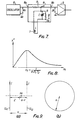
- the Helmholtz coil shown in Figures 9a and 9b is used as a magnet for generating the gradient magnetic field
- the magnetic field generated on the axis joining the centres of two coils CL 1 and CL 2 is in parallel with that axis and has an intensity given by the following equation: so that a magnetic field which has a gradient in the axial direction (i.e, in the direction Z) can be generated.
- "a" denotes the radius of the coils CL 1 and CL 2 and the distance in between
- I denotes the current to flow in the opposite directions through the two coils CL 1 and CL 2
- 3 denotes the distance from the coil CL 1 .
- magnets for generatiang the static magnetic field incidentally, either permanent magnets or electromagnetic magnets including super-conductive magnets, can be employed.
- the body P may be scanned with the frequency of the electromagnetic waves (or the vibrating magnetic field) as applied through the coil 7.
- the intensity of the static magnetic field is changed, the overall intensity is shifted, while the gradient of the magnetic field is maintained, so that the resonance point on the beam-shaped magnetic field is shifted, thereby to make it possible to effect the scanning operation.
- the static magnetic field is required to have a high stability, it is not advisable to change the intensity of the static magnetic field. It is therefore desirable to arrange a small variable static magnetic field in parallel with a large static magnetic field so that the intensity of the static magnetic field may be effected.
- the distribution and relaxation time of a specific atomic nucleus at any position in a body to be examined can be measured, so that the biochemical information concerning the inside of the body (especially information concerning malignant tissue or the like) can be obtained without any surgical operation.
- pulsating high-frequency waves may be generated in place of steady (or continuous) high-frequency waves from the oscillator 6 so that they irradiate the body P through the coil 7.
- the width tp of the pulses is defined by the following equation (giving so-called "90° pulses”).
- the signal i.e. the so-called “free induction decay” (FID) signal, which is induced in the coil 7 after the irradiation with the pulses, will decay with a time constant defined by the relaxation time T 2 .
- The.signal which results from subjecting the FID signal to the Fourier transformation, is known to give a resonance signal in the frequency of the aforementioned high-frequency waves.
- both the distribution of the specific atomic nucleus at each position of the beam-shaped magnetic field and the mean relaxation time T 2 can be attained without any scanning with the high-frequency waves and the magnetic field.
- the pulses (or the 90° pulses) for turning the magnetisation M along an axis Z 90° to an axis Y' in a rotating frame, as shown in Figure 10a, are applied.
- the magnetisation M decays at the time constant T 2 , while rotating in the coordinate X-Y plane as shown in the static frame in Figure lOb.
- the signal i.e. the FID signal
- the concentration distribution of the specific atomic nucleus for the resonance frequency ⁇ is attained, as shown in Figure 10d.
- the concentration distribution of the atomic nucleus and its relaxation time T 2 are instantly attained. If the latter pulses and the FID signal are taken for different positions of the body P, the concentration distribution of the specific atomic nucleus and its relaxation time T 2 are attained for the transverse section of the body P.
- the measurement of the relaxation time T 1 can be obtained by the so-called 180° pulse-t-90° method.
- 180° pulses are applied to turn the magnetisation M in the direction of -Z", as shown in Figure lla.
- the 90° pulses are applied, as shown in Figure llb, so that the initial value Mz (t) of the FID signal shown in Figure llc is obtained. If that value is plotted against the time t, the relationship expressed by the following equation is obtained, as shown in Figure lld. from which the relaxation time T 1 can be deduced.
Abstract
Description
- This invention relates to a nuclear magnetic resonance apparatus for measuring from outside of a body both the distribution of a specific atomic nucleus in the body to be examined and the relaxation time of the atomic nucleus by making use of the nuclear magnetic resonance (NMR) phenomena.
- The following types of non-invasive apparatus for examining the internal organs and tissues in a human body have been widely used in the prior art:
- X-ray apparatus (including computer tomography apparatus, i.e, a CT scanner);
- nuclear medical apparatus; and
- ultrasonic apparatus.
- The prior art apparatus measure mainly the physical properties of a human body. More specifically, X-ray apparatus discriminates between human tissues and defines their shapes in accordance with the differences in the X-ray transmission characteristics among the human tissues so that a variety of diseases or conditions can be identified. On the other hand, ultrasonic apparatus finds the differences in acoustic impedance among the human tissues thereby to discriminate between tissues and to measure their shapes and motions. However, the nuclear medical apparatus measures the distribution of a radioactive isotope, or.its compound, with which a human body has been dosed, and is thereby able to distinguish among the human tissues and to some extent determine the conditions of the respective tissues. Therefore, the nuclear medical apparatus aims mainly at gathering macroscopic information as to each tissue although it can obtain biological information to some extent.
- Thus, it is difficult for the conventional apparatus in examining a human body from the outside to gather biochemical information concerning the human tissues. More specifically, if the same X-ray transmission characteristic or acoustic impedance is exhibited, it is quite difficult to judge whether that particular tissue is biochemically normal or abnormal (e.g, cancerous). X-ray apparatus especially has the disadvantage of the exposure of the tissues of the body to X-rays from the outside of the body, and the nuclear medical apparatus has the disadvantage of the exposure of the tissues of the body to Y -rays from the inside of the body.
- As is well-known in the art, for example, examinations are widely performed at present to sample cells and take their photographs by means of a gastro-camera. Some tissues and fluids, such as blood, can also be biochemically analysed. The range of tissues that can be examined by this method is limited, and it is difficult to examine the tissues of different parts of a human body from the outside.
- By the use of the principle of the NMR, on the other hand it is possible to attain even biochemical information of the respective tissues in the human body from outside the body.
- First of all, the principle of the NMR will be generally explained.
- Atomic nuclei are composed of protons and neutrons. In some atomic nuclei,- the protons and neutrons spin as a whole like a top, having a nuclear spin angular momentum denominated I. For example, the atomic nucleus (1 H) of hydrogen is composed of a single proton having a spin expressed by a spin quantum number of 1/2, as shown in Figure la. Here, since the proton P has a positive electric charge e+, as shown in Figure lb, the phenomenon has the same electrical result as that produced when a current corresponding to the positive charge flow through a small coil in accordance with the spins of the nucleus so that a magnetic momentumis established. In other words, each hydrogen nucleus can be regarded as a small magnet.

- As is diagrammatically shown in Figure 2a and 2b, since a ferrogmagnetic element such as iron has its minute magnets oriented in the same direction (as shown in Figure 2a) magnetisation is observed as a whole. In the case of the aforementioned hydrogen, on the contrary, the directions of the respective magnetic momentums are at random (as shown in Figure 2b) so that magnetisation is not observed as a whole.
- If a static magnetic field Ho in a directionis applied to hydrogen, the respective atomic nuclei are rearranged in the direction Z of the static magnetic field Ho, i.e, the energy levels of the nuclei are quantised in the direction Z. This phenomena for the hydrogen nucleus is shown in Figure 3a. Since the spin quantum number of the hydrogen nucleus is 1/2, the energy level is divided into two levels, i.e. -1/2 and +1/2, as shown in Figure 3b, but most of the nuclei are oriented in the direction Z corresponding to the energy level of +1/2. The energy difference between two energy levels is given by the following equation:

 : h/2 π (h: Planck constant) If a force defined by
 =
=
Ho is applied to each atomic nucleus by a static magnetic fieldHO , the atomic nucleus performs a precession around the axis Z at an angular velocity defined by the following equation: Ho corresponding to the aforementioned energy difference Δ E until they transit to the next higher energy level.
- Even if several kinds of atomic nuclei having nuclear spin angular momentums are mixed, the gyromagnetic ratios δ are different among the respective atomic nuclei so that the resonance frequencies are accordingly different thereamong. Therefore, the resonance of a specific atomic nucleus can be extracted.
- Moreover, if the intensity of the resonance is measured, the quantity of the atomic nuclei in the area in question can be obtained. After the resonance, on the other hand, the atomic nucleus, which was excited to a higher energy level, after the time determined by a time constant called a relaxation time has elapsed, returns to its lower energy level. The relaxation time, especially the spin-lattice relaxation time denoted at Tl, is a time constant dependent upon the manner of combination of individual chemical compounds and is known to be very different for normal tissues and malignant tissues.
- Although the foregoing description has been directed to the atomic nucleus (lg) of hydrogen, other atomic nuclei having different nuclear spin angular momentumes can be used to perform similar-measurements. For example, in the usual chemical analysis, the atomic nucleus (-9 F) of fluorine, the atomic nucleus (31p) of phosphorus, the atomic nucleus (13C) of carbon and so on are employed in addition to the aforementioned atomic nucleus (l H) of hydrogen.
- Thus, since the quantity of a specific atomic nucleus existing and its relaxation time can be measured by the NMR, chemical information as to a specific atomic nucleus existing in a substance can be obtained.
- As an examining apparatus making use of NMR, there has been proposed an apparatus in which an NMR signal corresponding to each projection image of a body to be examined is measured in a number of directions with respect to the body on the basis of a similar principle to the so-called "first generation" i.e.translate-rotate type, CT scanner so that its intensity at each position of the body may be determined by the reconstructing method. ("Image Formation by Induced Local Interactions: Examples Employing Nuclear Magnetic Resonance," by P.C. Lauterbur, "NATURE" vol 242, March 16, 1973, pp 190-191).
- However, the apparatus proposed has a disadvantage in that it takes a long time to accomplish the measurements. Since it is difficult especially for the NMR to have a signal/noise (S/N) ratio as high as the X-ray, a measurement time larger than one order longer than that of the first generation CT scanner is required for accomplishing measurements which are worthy of examination.
- Accordingly this invention seeks to provide a nuclear magnetic resonance apparatus which can measure the distribution of a specific atomic nucleus in a body to be examined and its relaxation time on the basis of the NMR principle within a relatively short time period without any reconstructing processing.
- According to the invention there is provided nuclear magnetic resonance ("NMR") apparatus for registering the NMR of a specific atomic nucleus in a body, including magnet apparatus for generating a compound magnetic field having a specified configuration in the region of the body, oscillator apparatus for applying an oscillating electromagnetic field to the body, and means for detecting NMR signals from the body and reconstructing a display on the basis of NMR signals, characterised by means for forming the magnetic field into a narrow beam and means for providing relative movement of the body and the beam so as to scan the body with the beam.
- Preferably the body is moved relative to the beam.
- A preferred arrangement of the invention comprises a nuclear magnetic resonance apparatus for registering the nuclear magnetic resonance condition of atomic nuclei distributed in a body, the apparatus comprising:
- first magnetic field generating means for generating a homogeneous static magnetic field for application to a selected portion of the body;
- second magnetic field generating means for simultaneously generating a gradient magnetic field of smaller intensity than that of the beam-shaped static magnetic field and of such'distribution as to gradually increase or decrease in the direction of said beam-shaped static magnetic field;
- an oscillator for generating electromagnetic waves having a frequency corresponding to the nuclear magnetic resonance condition of the atomic nuclei to be measured;
- a coil wound around the body to be examined, at least a portion of said coil lying in said magnetic fields, impressing said electromagnetic waves upon said body and detecting the nuclear magnetic resonance in __said- body;
- a receiver for receiving and processing the nuclear magnetic resonance signal detected by said coil;
- a recorder for recording the nuclear magnetic resonance signal processed by said receiver in synchronism with the operation of said drive means for identifying the recorded resonance signal with the position of said body; and
- a display unit for reading the records as to a desired region of the body out of said recorder and for selectively or simultaneously displaying the distribution and relaxation time of the relevant atomic nuclei in said body; the first magnetic field generating means is arranged so that the static magnetic field is in the form of a narrow beam, and in the drive means are provided for moving the body in a direction perpendicular to the direction of said beam.
- The invention also extends to a method for determining the distribution of specific atomic nuclei in a body comprising the steps of:
- applying a homogeneous static magnetic field in the form of a narrow beam through a selected portion of the body;
- superimposing on the static magnetic field a gradient magnetic field of smaller intensity than the static magnetic field and bf such distribution as to gradually increase or decrease in the direction of the beam-shaped magnetic field; and
- impressing electromagnetic waves on the body in a planar configuration within said narrow beam for identifying the nuclear magnetic resonance of the atomic nuceli, the source of said electromagnetic waves being at known distance from said body.
- Some embodiments of the invention will now be described by way of example with reference to the accompanying drawings, in which Figures 1 to 3 illustrate the general principles of NMR as explained above, i.e.
- Figures la and lb are schematic diagrams for explaining nuclear magnetic momentum;
- Figures 2a and 2b are schematic diagrams illustrating the directionality of nuclear magnetic momentum;
- Figures 3a and 3b are schematic diagrams illustrating the alignment of the nuclear magnetic momentum by a static magnetic field;
- Figures 4 to 10 refer specifically to the present invention as follows:
- Figure 4 is a block diagram showing the construction of one embodiment of this invention;
- Figures 5a to 5c, Figure 6 and Figure 8 are views and graphs for explaining the embodiment of Figure 4;
- Figure 7 is a circuit diagram showing in detail a portion of the construction of the embodiment of Figure 4;
- Figures 9a and 9b are schematic views for explaining the Helmholtz coil as an example of means for generating a gradient magnetic field; and
- Figures 10a to 10d and Figures lla to lld are schematic views for explaining other embodiments of the invention.
- Referring to Figure 4, first magnet means is composed of a pair of magnets, such as electromagnets driven by a D.C. stabilised
power supply 12, to generate a homogeneous static magnetic field. Shims (or pole pieces) 2 of a magnetic substance are magnetically and slidably mounted to protrude from the facing magnetic pole plates of the pair first magnet means for focusing the homogeneous static magnetic field generated by the first magnet means into a thin beam (or the so-called "pencil beam") shape. - Second magnet means 3 is composed of a pair of magnets such as a Helmholtz coil driven by a stabilised power supply for generating, in addition to the beam-shaped magnetic field focused by the shims, a gradient magnetic field having such an intensity as is distributed to gradually increase or decrease in the direction of the beam.
- A body holder 4, such as a bed structure, supports a body P to be examined. Drive means 5 may drive the body holder 4 so as to drive the body P in either of two directions perpendicular to the aforementioned beam and to each other as required to expose the portion of the body under examination to the magnetic fields and the electromagntic waves.
- An
oscillator 6 generates a signal having a frequency corresponding to the NMR condition of an atomic nucleus to be measured. Acoil 7 is wound around the body P for applying the signal generated by theoscillator 6 in the form of electromagnetic waves to the body P and for detecting the NMR at the body P. A so-called "bridge-type receiver" 8 transmits the output signal of theoscillator 6 to thecoil 7 and receives the NMR signal from thecoil 7. A phase-sensitive AM amplifier 9 detects and amplifies the NMR signal received and detected by thereceiver 8. Arecorder 10 records the output of theamplifier 9 in a manner to correspond to the position in the body P with reference to the drive signals of the drive means 5. A display unit 11 reads the record out of therecorder 10 and displays the record for read out. - In this instance, the first magnet means 1 and the
shims 2 constitute first magnetic field generating means for generating a homogeneous static magnetic field in the form of a narrow beam, whereas the second magnet means 3 constitutes the second magnetic field generating means for generating a gradient magnetic field. - With the construction thus far described, the body P is irradiated with a focused thin magnetic field Ha, as shown in Figures 5a to 5c, which is focused from a homogenous static magnetic field Ho by the actions of both the first magnet means 1 for generating the homogeneous static magnetic field Ho and the
shims 2 disposed to protrude from the facing magnetic pole plates of the first magnet means 1 for focusing the magnetic field into a beam. The other magnetic field, with which the body is irradiated by the second magnet means generating the gradient magnetic field, has an intensity as of about 1/100 or less than the homogeneous static magnetic field Ho and has a gradually differing intensity (in the direction Z) within the body P. - In addition, high-frequency waves generated by the
oscillator 6, which is operative to oscillate in a frequency within the band of the resonance frequency ω, are applied as electromagnetic waves to the body P through thecoil 7 wound around the body P. - Simultaneously, a resonance signal is extracted by the bridge-
type receiver 8 to generate an output corresponding to the change in the resonance of the received signal from the input signal from theoscillator 6. After this output has been amplified by theamplifier 9, the resonance intensity, is fed to therecorder 10. Thisrecorder 10 is also fed with a moving position signal from the driving means 5, which is operative to mechanically move the body holder 4, so that it may record the intensity of the resonance signal in a manner to correspond to the respective positions of the body P. The results are displayed in the display unit 11 so that they may be used for visual examination. - More specifically, the body P has a portion exposed to a magnetic field which is the summation of the beam-shaped homogenous static magnetic field Ha and the gradient magnetic field Hb. The overall magnetic field (Ha + Hb) is very narrow in the X, Y plane and, as shown in Figure 5b, and is gradient in the direction Z, as shown in Figure 5c. As has been described above, since there holds between the intensity H of the magnetic field and the resonance frequency the following relationship:

direction 9 due to the influence of the gradient magnetic field, as shown in Figure 6. - If the resonance signal is taken at different successive frequencies generated by the
oscillator 6, the result is that a beam-shaped slender column region is scanned. The range to be scanned can be suitably selected by selecting the frequency range to be generated. By repeating similar scanning operations at different positions of the body P, the NMR resonance signal at any region can be extracted not only from the transverse section of the body P but also from the flat or curved plane in any direction. - The
bridge type receiver 8 is constructed as shown in Figure 7. A resistor RL is connected between aninput terminal 8a, to which theoscillator 6 is connected, and anoutput terminal 8b which is connected to theamplifier 9. A parallel circuit, including a variable capacitor C and resistor RBI is connected across the terminals of thecoil 7. One common terminal A of thecoil 7 and the parallel circuit is connected between the resistor RL and theoutput terminal 8b and the other common terminal B is grounded. If the variable capacitor C is adjusted for the inductance L of the coil as determined by the following equation:


- By detecting and amplifying this voltage difference Δ V by means of the
amplifier 9, the nuclear magnetic resonance signal of the desired atomic nuclei can extracted. This resonance signal is fed to therecorder 10 simultaneously with the signal showing the position of the body P, so that the level of the resonance signal corresponding to each position is recorded in therecorder 10. If the signal level is displayed in the display unit 11, the distribution of the specific atomic nuclei in each position of the body P can be obtained. - The foregoing description has been directed to the case, in which continuous high-frequency waves are generated from the
oscillator 6 so that the distribution of the specific atomic nuclei in each position of the body P may be measured. In order to measure the relaxation time of the specific atomic nuclei in the body, the resonance intensity at a resonance point is measured while varying the intensity H1 of the vibrating magnetic field emitted from thecoil 7 toward the object P. The values of the resonance intensity measured have a tendency to first increase with the increase in the intensity H1 of the vibrating magnetic field and to then decrease, as shown in Figure 8. The condition for the maximum intensity is given by the following equation:
- If, on the other hand, the Helmholtz coil shown in Figures 9a and 9b is used as a magnet for generating the gradient magnetic field, the magnetic field generated on the axis joining the centres of two coils CL1 and CL2 is in parallel with that axis and has an intensity given by the following equation:

- As the magnets for generatiang the static magnetic field, incidentally, either permanent magnets or electromagnetic magnets including super-conductive magnets, can be employed.
- As a method of scanning with the beam-shaped static magnetic field, the body P may be scanned with the frequency of the electromagnetic waves (or the vibrating magnetic field) as applied through the
coil 7. In addition, if the intensity of the static magnetic field is changed, the overall intensity is shifted, while the gradient of the magnetic field is maintained, so that the resonance point on the beam-shaped magnetic field is shifted, thereby to make it possible to effect the scanning operation. However, since the static magnetic field is required to have a high stability, it is not advisable to change the intensity of the static magnetic field. It is therefore desirable to arrange a small variable static magnetic field in parallel with a large static magnetic field so that the intensity of the static magnetic field may be effected. - Thus, the distribution and relaxation time of a specific atomic nucleus at any position in a body to be examined can be measured, so that the biochemical information concerning the inside of the body (especially information concerning malignant tissue or the like) can be obtained without any surgical operation.
- Incidentally, this invention is not limited only to the embodiment thus far described with reference to the accompanying drawings but can be variously modified and practiced within such a range as is free from changing the inventive concept thereof.
- For example, pulsating high-frequency waves may be generated in place of steady (or continuous) high-frequency waves from the
oscillator 6 so that they irradiate the body P through thecoil 7. If, at this time, the width tp of the pulses is defined by the following equation (giving so-called "90° pulses").
coil 7 after the irradiation with the pulses, will decay with a time constant defined by the relaxation time T2. The.signal, which results from subjecting the FID signal to the Fourier transformation, is known to give a resonance signal in the frequency of the aforementioned high-frequency waves. - If the 90° pulses are applied, while the gradient magnetic field is being applied, so that the FID signal is amplified by the
amplifier 9 and simultaneously subjected to the Fourier transformation, both the distribution of the specific atomic nucleus at each position of the beam-shaped magnetic field and the mean relaxation time T2 can be attained without any scanning with the high-frequency waves and the magnetic field. These processes will be explained in more detail with reference to Figures 10a to 10d. - The pulses (or the 90° pulses) for turning the magnetisation M along an axis Z 90° to an axis Y' in a rotating frame, as shown in Figure 10a, are applied. After that, the magnetisation M decays at the time constant T2, while rotating in the coordinate X-Y plane as shown in the static frame in Figure lOb. As a result, there is established in the
coil 7 the signal, i.e. the FID signal, which is to be excited by the motions of that magnetisation M, as shown in Figure 10c. If the decay due to the time constant T2 is subtracted from that of the FID signal and then the Fourier transformation is performed, the concentration distribution of the specific atomic nucleus for the resonance frequency ω is attained, as shown in Figure 10d. - Since the difference in the resonance frequency ω is made to correspond to the displacement of the position in the directionby the gradient magnetic field, .the concentration distribution of the atomic nucleus and its relaxation time T2 are instantly attained. If the latter pulses and the FID signal are taken for different positions of the body P, the concentration distribution of the specific atomic nucleus and its relaxation time T2 are attained for the transverse section of the body P.

- The measurement of the relaxation time T1 can be obtained by the so-called 180° pulse-t-90° method. First, 180° pulses are applied to turn the magnetisation M in the direction of -Z", as shown in Figure lla. After the relaxation for the time t, the 90° pulses are applied, as shown in Figure llb, so that the initial value Mz (t) of the FID signal shown in Figure llc is obtained. If that value is plotted against the time t, the relationship expressed by the following equation is obtained, as shown in Figure lld.

- Alternatively, if the NMR signal is taken at different positions of the shims for focusing the static magnetic field into a beam on the object P along a transverse section, similar results can be obtained, to those obtained by moving the body.
Each of these apparatus has its respective advantages and disadvanatages. For the purpose herein, only brief descriptions are set out as necessary for comparison with the NMR apparatus according to the invention.
Claims (13)
Applications Claiming Priority (2)
| Application Number | Priority Date | Filing Date | Title |
|---|---|---|---|
| JP7978880A JPS576347A (en) | 1980-06-13 | 1980-06-13 | Nuclear magnetic resonator |
| JP79788/80 | 1980-06-13 |
Publications (2)
| Publication Number | Publication Date |
|---|---|
| EP0042255A1 true EP0042255A1 (en) | 1981-12-23 |
| EP0042255B1 EP0042255B1 (en) | 1985-09-11 |
Family
ID=13699945
Family Applications (1)
| Application Number | Title | Priority Date | Filing Date |
|---|---|---|---|
| EP81302589A Expired EP0042255B1 (en) | 1980-06-13 | 1981-06-10 | Method and apparatus for nuclear magnetic resonance |
Country Status (4)
| Country | Link |
|---|---|
| US (1) | US4429277A (en) |
| EP (1) | EP0042255B1 (en) |
| JP (1) | JPS576347A (en) |
| DE (1) | DE3172216D1 (en) |
Cited By (5)
| Publication number | Priority date | Publication date | Assignee | Title |
|---|---|---|---|---|
| EP0108421A2 (en) * | 1982-11-08 | 1984-05-16 | Kabushiki Kaisha Toshiba | Nuclear magnetic resonance diagnostic apparatus |
| EP0125339A2 (en) * | 1982-08-31 | 1984-11-21 | Kabushiki Kaisha Toshiba | Diagnostic apparatus using NMR |
| EP0187389A2 (en) * | 1984-12-30 | 1986-07-16 | Asahi Kasei Kogyo Kabushiki Kaisha | Apparatus for obtaining image information through use of a nuclear magnetic resonance signal |
| DE3639140A1 (en) * | 1985-11-18 | 1987-05-21 | Toshiba Kawasaki Kk | MAGNETIC RESONANCE SYSTEM |
| DE3938370A1 (en) * | 1989-11-18 | 1991-05-23 | Philips Patentverwaltung | Nuclear spin tomography method and nuclear spin tomography for performing the method |
Families Citing this family (6)
| Publication number | Priority date | Publication date | Assignee | Title |
|---|---|---|---|---|
| JPS5964108U (en) * | 1982-10-22 | 1984-04-27 | 持田製薬株式会社 | Attached equipment for NMR |
| DE3245945A1 (en) * | 1982-12-11 | 1984-06-14 | Bruker Analytische Meßtechnik GmbH, 7512 Rheinstetten | ELECTROMAGNET FOR NMR TOMOGRAPHY |
| US4520316A (en) * | 1983-04-25 | 1985-05-28 | The University Of British Columbia | NMR imaging technique |
| US4931760A (en) * | 1986-10-08 | 1990-06-05 | Asahi Kasei Kogyo Kabushiki Kaisha | Uniform magnetic field generator |
| US4984573A (en) * | 1987-06-23 | 1991-01-15 | Hafslund Nycomed Innovation Ab | Method of electron spin resonance enhanced magnetic resonance imaging |
| DE102010063128B3 (en) * | 2010-12-15 | 2012-06-14 | Siemens Aktiengesellschaft | A magnetic resonance apparatus |
Citations (4)
| Publication number | Priority date | Publication date | Assignee | Title |
|---|---|---|---|---|
| US3789832A (en) * | 1972-03-17 | 1974-02-05 | R Damadian | Apparatus and method for detecting cancer in tissue |
| DE2946847A1 (en) * | 1978-11-20 | 1980-05-29 | Damadian Raymond V | METHOD AND DEVICE OF THE NUCLEAR RESONANCE SPECTROSCOPY WITH SCANING AND RECORDING |
| DE3020385A1 (en) * | 1979-06-01 | 1980-12-11 | Instrumentarium Oy | NMR DIAGNOSTIC DEVICE |
| US4240439A (en) * | 1975-04-30 | 1980-12-23 | Hokkaido University | Method of obtaining information of a specified or target area of a living body near its skin surface by the application of a nuclear magnetic resonance phenomenon |
Family Cites Families (1)
| Publication number | Priority date | Publication date | Assignee | Title |
|---|---|---|---|---|
| JPS574541A (en) * | 1980-06-12 | 1982-01-11 | Toshiba Corp | Nuclear magnetic resonance apparatus |
-
1980
- 1980-06-13 JP JP7978880A patent/JPS576347A/en active Pending
-
1981
- 1981-05-20 US US06/265,643 patent/US4429277A/en not_active Expired - Fee Related
- 1981-06-10 EP EP81302589A patent/EP0042255B1/en not_active Expired
- 1981-06-10 DE DE8181302589T patent/DE3172216D1/en not_active Expired
Patent Citations (4)
| Publication number | Priority date | Publication date | Assignee | Title |
|---|---|---|---|---|
| US3789832A (en) * | 1972-03-17 | 1974-02-05 | R Damadian | Apparatus and method for detecting cancer in tissue |
| US4240439A (en) * | 1975-04-30 | 1980-12-23 | Hokkaido University | Method of obtaining information of a specified or target area of a living body near its skin surface by the application of a nuclear magnetic resonance phenomenon |
| DE2946847A1 (en) * | 1978-11-20 | 1980-05-29 | Damadian Raymond V | METHOD AND DEVICE OF THE NUCLEAR RESONANCE SPECTROSCOPY WITH SCANING AND RECORDING |
| DE3020385A1 (en) * | 1979-06-01 | 1980-12-11 | Instrumentarium Oy | NMR DIAGNOSTIC DEVICE |
Cited By (11)
| Publication number | Priority date | Publication date | Assignee | Title |
|---|---|---|---|---|
| EP0125339A2 (en) * | 1982-08-31 | 1984-11-21 | Kabushiki Kaisha Toshiba | Diagnostic apparatus using NMR |
| EP0125339A3 (en) * | 1982-08-31 | 1985-06-05 | Kabushiki Kaisha Toshiba | Diagnostic apparatus using nmr |
| EP0108421A2 (en) * | 1982-11-08 | 1984-05-16 | Kabushiki Kaisha Toshiba | Nuclear magnetic resonance diagnostic apparatus |
| EP0108421A3 (en) * | 1982-11-08 | 1985-07-31 | Kabushiki Kaisha Toshiba | Nuclear magnetic resonance diagnostic apparatus |
| US4656423A (en) * | 1982-11-08 | 1987-04-07 | Tokyo Shibaura Denki Kabushiki Kaisha | Nuclear magnetic resonance diagnostic apparatus |
| EP0187389A2 (en) * | 1984-12-30 | 1986-07-16 | Asahi Kasei Kogyo Kabushiki Kaisha | Apparatus for obtaining image information through use of a nuclear magnetic resonance signal |
| EP0187389A3 (en) * | 1984-12-30 | 1987-05-27 | Asahi Kasei Kogyo Kabushiki Kaisha | Apparatus for obtaining image information through use of a nuclear magnetic resonance signal |
| US4727327A (en) * | 1984-12-30 | 1988-02-23 | Hideo Toyoshima | Apparatus for obtaining image information through use of a nuclear magnetic resonance signal |
| DE3639140A1 (en) * | 1985-11-18 | 1987-05-21 | Toshiba Kawasaki Kk | MAGNETIC RESONANCE SYSTEM |
| US4875485A (en) * | 1985-11-18 | 1989-10-24 | Kabushiki Kaisha Toshiba | Magnetic resonance system |
| DE3938370A1 (en) * | 1989-11-18 | 1991-05-23 | Philips Patentverwaltung | Nuclear spin tomography method and nuclear spin tomography for performing the method |
Also Published As
| Publication number | Publication date |
|---|---|
| DE3172216D1 (en) | 1985-10-17 |
| JPS576347A (en) | 1982-01-13 |
| EP0042255B1 (en) | 1985-09-11 |
| US4429277A (en) | 1984-01-31 |
Similar Documents
| Publication | Publication Date | Title |
|---|---|---|
| US6246895B1 (en) | Imaging of ultrasonic fields with MRI | |
| KR900007541B1 (en) | Blood vessel projection imaging system using nuclear magnetic resonance | |
| US4543959A (en) | Diagnosis apparatus and the determination of tissue structure and quality | |
| EP0042254B2 (en) | Nuclear resonance apparatus including means for rotating the gradient of a magnetic field | |
| US5263482A (en) | Thermographic imaging | |
| JPH0624527B2 (en) | Nuclear magnetic resonance imaging method | |
| JPS605138A (en) | Generation of signal showing fluid flow amount | |
| JPH06507794A (en) | NQR test method and device | |
| EP0412819A2 (en) | NMR imaging | |
| US4520828A (en) | Nuclear magnetic resonance method and apparatus | |
| JPH04503612A (en) | magnetic resonance imaging | |
| EP0042255B1 (en) | Method and apparatus for nuclear magnetic resonance | |
| JPH0337931B2 (en) | ||
| JP3656654B2 (en) | Simultaneous detection method of velocity and acceleration distribution of moving fluid | |
| JPH0365971B2 (en) | ||
| Bottomley | In vivo tumor discrimination in a rat by proton nuclear magnetic resonance imaging | |
| JPS61155741A (en) | Method of mapping substance characteristic | |
| Bottomley | Nuclear magnetic resonance: Beyond physical imaging: A powerful new diagnostic tool that uses magnetic fields and radio waves creates pictures of the body's internal chemistry | |
| JPS614952A (en) | Method of mapping nuclear magnetic characteristic of body tobe inspected | |
| JP3708135B2 (en) | Magnetic resonance imaging system | |
| JPH0670911A (en) | Magnetic resonance image device | |
| JPS6244231A (en) | Diagnostic magnetic resonance imaging apparatus | |
| JPS63222754A (en) | Probe | |
| JP2005237970A (en) | Method and system for mapping oxygen concentration over whole interested region | |
| Williams et al. | Nuclear magnetic resonance (NMR) imaging in urologic oncology |
Legal Events
| Date | Code | Title | Description |
|---|---|---|---|
| PUAI | Public reference made under article 153(3) epc to a published international application that has entered the european phase |
Free format text: ORIGINAL CODE: 0009012 |
|
| AK | Designated contracting states |
Designated state(s): DE FR GB NL |
|
| 17P | Request for examination filed |
Effective date: 19820528 |
|
| RAP1 | Party data changed (applicant data changed or rights of an application transferred) |
Owner name: KABUSHIKI KAISHA TOSHIBA |
|
| GRAA | (expected) grant |
Free format text: ORIGINAL CODE: 0009210 |
|
| AK | Designated contracting states |
Designated state(s): DE FR GB NL |
|
| REF | Corresponds to: |
Ref document number: 3172216 Country of ref document: DE Date of ref document: 19851017 |
|
| ET | Fr: translation filed | ||
| PLBE | No opposition filed within time limit |
Free format text: ORIGINAL CODE: 0009261 |
|
| STAA | Information on the status of an ep patent application or granted ep patent |
Free format text: STATUS: NO OPPOSITION FILED WITHIN TIME LIMIT |
|
| 26N | No opposition filed | ||
| REG | Reference to a national code |
Ref country code: GB Ref legal event code: 746 |
|
| PGFP | Annual fee paid to national office [announced via postgrant information from national office to epo] |
Ref country code: NL Payment date: 19870630 Year of fee payment: 7 |
|
| PG25 | Lapsed in a contracting state [announced via postgrant information from national office to epo] |
Ref country code: GB Effective date: 19890610 |
|
| PG25 | Lapsed in a contracting state [announced via postgrant information from national office to epo] |
Ref country code: NL Effective date: 19900101 |
|
| GBPC | Gb: european patent ceased through non-payment of renewal fee | ||
| NLV4 | Nl: lapsed or anulled due to non-payment of the annual fee | ||
| PG25 | Lapsed in a contracting state [announced via postgrant information from national office to epo] |
Ref country code: FR Free format text: LAPSE BECAUSE OF NON-PAYMENT OF DUE FEES Effective date: 19900228 |
|
| PG25 | Lapsed in a contracting state [announced via postgrant information from national office to epo] |
Ref country code: DE Effective date: 19900301 |
|
| REG | Reference to a national code |
Ref country code: FR Ref legal event code: ST |