EP0039464B1 - Electronic musical instrument - Google Patents
Electronic musical instrument Download PDFInfo
- Publication number
- EP0039464B1 EP0039464B1 EP81103158A EP81103158A EP0039464B1 EP 0039464 B1 EP0039464 B1 EP 0039464B1 EP 81103158 A EP81103158 A EP 81103158A EP 81103158 A EP81103158 A EP 81103158A EP 0039464 B1 EP0039464 B1 EP 0039464B1
- Authority
- EP
- European Patent Office
- Prior art keywords
- chord
- keyboard
- key
- information
- depressed
- Prior art date
- Legal status (The legal status is an assumption and is not a legal conclusion. Google has not performed a legal analysis and makes no representation as to the accuracy of the status listed.)
- Expired
Links
Images


Classifications
-
- G—PHYSICS
- G10—MUSICAL INSTRUMENTS; ACOUSTICS
- G10H—ELECTROPHONIC MUSICAL INSTRUMENTS; INSTRUMENTS IN WHICH THE TONES ARE GENERATED BY ELECTROMECHANICAL MEANS OR ELECTRONIC GENERATORS, OR IN WHICH THE TONES ARE SYNTHESISED FROM A DATA STORE
- G10H1/00—Details of electrophonic musical instruments
- G10H1/36—Accompaniment arrangements
- G10H1/38—Chord
- G10H1/386—One-finger or one-key chord systems
-
- Y—GENERAL TAGGING OF NEW TECHNOLOGICAL DEVELOPMENTS; GENERAL TAGGING OF CROSS-SECTIONAL TECHNOLOGIES SPANNING OVER SEVERAL SECTIONS OF THE IPC; TECHNICAL SUBJECTS COVERED BY FORMER USPC CROSS-REFERENCE ART COLLECTIONS [XRACs] AND DIGESTS
- Y10—TECHNICAL SUBJECTS COVERED BY FORMER USPC
- Y10S—TECHNICAL SUBJECTS COVERED BY FORMER USPC CROSS-REFERENCE ART COLLECTIONS [XRACs] AND DIGESTS
- Y10S84/00—Music
- Y10S84/22—Chord organs
Definitions
- the invention relates to an electronic musical instrument comprising a keyboard apparatus for players to perform a melody or accompaniment of music, a keyboard information detecting means for detecting information on the key depressed by said keyboard apparatus, and a chord distinguishing means for distinguishing the chord, wherein the keyboard information detecting means is composed of a hand keyboard information detecting means for detecting the note name of the depressed key information of the hand keyboard.
- a record button was depressed to put the chord storing apparatus into a record condition, a method of determining a chord was selected by a musical performance mode specifying button, a chord was determined through depression of the keyboard or the like in accordance with the musical performance mode, and the inputting operation of the chord length specification for determining the length of the chord had to be performed.
- the musical performance mode specification button means a button for determining a musical performance mode such as a one finger mode, which is a musical performing method of determining a chord through depression of one key of the keyboard, a finger mode, which is a musical performing method of determining a chord through depression of a plurality of hand keyboards in accordance with the composing sound of the chord, or a separated pedal mode, which is a performing method for determining the chord through selection of the bass sound of the chord, by a pedal keyboard or foot keyboard, through the depression of the composing sound of the chord by a manual keyboard or hand keyboard (hereinafter they are referred to as one finger mode, finger mode, separated pedal mode, and are called musical performance mode in a general term).
- a musical performance mode such as a one finger mode, which is a musical performing method of determining a chord through depression of one key of the keyboard, a finger mode, which is a musical performing method of determining a chord through depression of a plurality of hand keyboards in accordance with the composing sound of the
- a manual keyboard or hand keyboard 1 is connected to a circuit 2 for detecting depressed key note names.
- a note name corresponding to the keyboard depressed by the hand keyboard 1 is depressed so that hand keyboard note name information can be provided.
- a pedal keyboard or foot keyboard 3 is connected to a circuit 4 for detecting depressed note names.
- a note name corresponding to the keyboard depressed by the foot keyboard 3 is detected so that foot keyboard note name information can be provided.
- a circuit 5 for specifying a finger chord type specifies the information of chord types (major, minor, seventh, etc.) in the one finger mode, whereby the chord type information for one finger use is provided.
- a circuit 6 for specifying musical performance specifies the performance mode in accordance with the musical performance mode of the one finger, finger or the like selected by the performer.
- a circuit 7 for distinguishing chords distinguishes chords, to which the musical performance mode information, the hand keyboard note name information, the foot keyboard note name information, the chord type information for one finger are inputted, distinguishes chords depressed by the hand keyboard note name information, the foot keyboard note name information and the chord type information for one finger use in accordance with the performance mode thereby to detect the information (C major, E minor, etc.) of the chords.
- a chord information detecting apparatus 8 which is composed of the hand keyboard 1, the depressed key note name detecting circuit 2, the foot keyboard 3, the depressed key note name detecting circuit 4 and the chord type specifying circuit 5 for one finger use as described hereinabove, detects the chord information of the keyboard depressed in accordance with the musical performance mode.
- a chord length specifying circuit 9 outputs the information of the length to be continued (one bar, half a bar, etc.) of the chord information and length information are stored in a memory 11 by a write circuit 10.
- the chord detecting apparatus 8 had no functions for automatically detecting the musical performance mode.
- the musical-performance-mode specifying circuit 6 had to be operated to specify the musical performance mode, thus resulting in extremely difficult operation.
- an electronic musical instrument having an automatic accompaniment apparatus which comprises a chord name detecting circuit, an encoder circuit, a selection circuit, a decoder circuit and a tone producing circuit.
- the automatic accompaniment apparatus it is only possible by the automatic accompaniment apparatus to select optionally either a first automatic accompaniment mode or a second automatic accompaniment mode.
- a function for automatically detecting the musical performance mode should be provided by the conditions of the hand keyboard, the foot keyboard, the chord type specifying circuit for one finger use, etc., to simplify the operation causing the chord to be stored.
- an electronic musical instrument as defined above is characterized in that the hand keyboard information detecting means further comprises a depressed-key detecting means for detecting the number of keys depressed, and that information specifying the number of the detected depressed keys is given to a musical performance mode detecting means which detects a performing mode according to the output from said depressed-key detecting means and selected from one finger mode, finger mode and separated pedal mode and which detects the chord in accordance with the output from said keyboard information detecting means and the output from said performing mode detecting means.
- a hand keyboard 1 is connected to a hand keyboard information detecting apparatus 14 composed of a depressed key note name detecting circuit 12 and a depressed-key-number detecting circuit 13 so that the depressed key note name and the depressed-key-number of a key depressed by the hand keyboard 1 are automatically detected.
- Fig. 3 shows the sequence of the hand keyboard information detecting apparatus 14.
- the hand keyboard information detecting apparatus 14 is provided with four note-name information registers and one depressed-key-number register, these registers being shown in Fig. 3. The sequence of these registers will be described hereinafter with reference of Fig. 3.
- the note name information register and the depressed-key-number register are initially cleared and then the scanning operation of the hand keyboard 1 starts.
- note-name information corresponding to a key depressed by the hand keyboard is sequentially stored in the note name information register. Simultaneously the number of the depressed keys is counted and the counted results are accumulated in the depressed-key-number register.
- the hand keyboard information detecting apparatus 14 stores the note name information of the depressed key and the depressed-key-number of the hand keyboard 1 are stored in the respective registers through the sequence operation in accordance with Fig. 3.
- a foot keyboard 3 which is composed of a depressed key note name detecting circuit 15 and a depressed key detecting circuit 16, is connected to a foot keyboard information detecting apparatus 17 to detect the note name information of a key depressed by the foot keyboard 3 and the existence of the depressed key.
- the note name information which is one note, will do.
- the number of the depressed keys is not required to be detected. All that is required to be done is to detect whether or not the depressed key exists.
- the sequence of the foot keyboard information detecting apparatus 17 is not required to be fully described, since the sequence is similar to the sequence (see Fig. 3) of the hand keyboard information detecting apparatus 14.
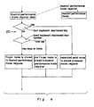
- a musical performance mode detecting circuit 20 of Fig. 2 automatically detects the musical performance mode by a hand keyboard depressed-key-number information to be provided by a depressed-key-number detecting circuit 13 and a foot keyboard depressed key information to be provided by a depressed-key detecting circuit 16.
- the sequence of a musical performance mode detecting circuit 20 will be described hereinafter with reference of Fig. 4.
- the foot keyboard depressed-key information is distinguished and the foot keyboard is kept depressed, the musical performance mode becomes a separated pedal.
- the hand keyboard depressed-by-number information is distinguished.
- the depressed key of the hand keybord is one, the mode becomes a one finger' mode.
- the mode becomes a fingered mode.
- Each of these modes is stored in the musical performance mode register shown in Fig. 4.
- a chord type specifying circuit 18 specifies the type (minor, seventh, etc.) of the chords to output the chord type specifying information, which is composed of specification existence information and chord type information in the existence of the specification.
- a chord distinguishing circuit 19 distinguishes the chords (C major, E minor, etc.), in accordance with a musical performance mode detected by a musical performance mode detecting circuit 20, by a hand keyboard note name information to be provided from a depressed-key-note-name detecting circuit 12, a foot keyboard note name information to be provided from the depressed-key-note-name detecting circuit 15 and a chord type specified information to be specified by the chord type specifying circuit 18.
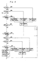
- Fig. 5 and Fig. 6 show the sequence of the chord distinguishing circuit.
- the root (C, E, etc.) and type (major, minor, etc.) of the chord are provided. The sequence will be described in accordance with Fig. 5 and Fig. 6.
- a root register for storing the root of a chord distinguished as a register and a type register for storing the chord type are used, which are described in Fig. 5.
- the root register and the type register are reset for the first time.
- the musical performance mode detected by the musical performance mode detecting circuit 20 is distinguished. In the case of one finger, the hand keyboard note name information is'stored as the root and the major is stored as the type.
- the chord distinguishing operation which has such sequence as described in Fig. 6 is performed.
- the difference of the chord distinguishing operation therebetween is the hand keyboard note name information in the case of the finger mode, and the foot keyboard note name information and the hand keyboard note name information in the case of the separated pedal.
- the note name information is sequentially distinguished as to which chord corresponding to the information.
- the type and root of the chord are stored.
- one note from the note name information is selected as a root and is stored in the root register.
- the major is stored in the type register as the chord type information.
- the type register is corrected to the type information of the chord type specifying circuit 18, only when the specifying operation exists, by the chord specification existence information of the chord type specifying circuit 18 of Fig. 2 as shown in Fig. 5.
- chord information (root and type) provided as described hereinabove by the chord distinguishing apparatus 21 of Fig. 2 and the length information of the chord length specifying circuit 9 are written in the memory 11 by a write circuit 10.
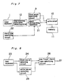
- Fig. 7 shows an embodiment in the case of two types of one finger and the finger mode as the musical performance mode.
- the depressed key of the hand keyboard 1 is converted into the note name information by the depressed key note name detecting circuit 12.
- the chord distinguishing operation which is equal to the sequence of Fig. 6, is performed by the chord distinguishing apparatus 21, which has the equal sequence to the finger mode of Fig. 5.
- the type register is corrected by the chord specification existence information of the chord type specifying circuit 22 of Fig. 7 and the chord type information to make the chord information (root and type).
- the length information of the chord of the chord length specifying circuit 9 and the chord are written in the memory 11 by the write circuit 10.
- the specification inputting apparatus of a chord type specifying circuit 22 in Fig. 7 is constructed by the use of a foot keyboard.
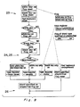
- Four chord types are provided through the on and off condition of the black key and the white key.
- Fig. 9 shows a flow chart, which has the operational sequence of Fig. 8 collected. According to the description of the sequence, the distinguishing operation is made to the minor seven when the white key and the black key are both on by the depressed key condition of the foot keyboard, to the seventh when the white key only is on, and to the minor when the black key only is on, depending upon the condition of the depressed key of the foot keyboard. It is judged that the chord specification exists upon storing in the chord type register and no chord specification exists when the foot keyboard is not depressed. When no chord specification exists, the type of the chord becomes major in Fig. 7 so that four chord types of major, minor, seventh and minor seventh are provided.
- the hand keyboard information detecting apparatus 14, the foot keyboard information detecting apparatus 17, the chord distinguishing apparatus 21, etc. of Fig. 2 are composed of microprocessors.
- the sequence shown in Fig. 3, Fig. 4, Fig. 5 and Fig. 6 may be carried out in accordance with a program. The same thing can be said even about the embodiment of Fig. 7 through Fig. 9.
- the musical performance mode is not required to be specified in the chord storing operation so that the operation can be simplified and the operational errors can be reduced.
Description
- The invention relates to an electronic musical instrument comprising a keyboard apparatus for players to perform a melody or accompaniment of music, a keyboard information detecting means for detecting information on the key depressed by said keyboard apparatus, and a chord distinguishing means for distinguishing the chord, wherein the keyboard information detecting means is composed of a hand keyboard information detecting means for detecting the note name of the depressed key information of the hand keyboard.
- In a chord storing apparatus of conventional electronic musical instruments, to cause the chord to be stored, a record button was depressed to put the chord storing apparatus into a record condition, a method of determining a chord was selected by a musical performance mode specifying button, a chord was determined through depression of the keyboard or the like in accordance with the musical performance mode, and the inputting operation of the chord length specification for determining the length of the chord had to be performed. The musical performance mode specification button means a button for determining a musical performance mode such as a one finger mode, which is a musical performing method of determining a chord through depression of one key of the keyboard, a finger mode, which is a musical performing method of determining a chord through depression of a plurality of hand keyboards in accordance with the composing sound of the chord, or a separated pedal mode, which is a performing method for determining the chord through selection of the bass sound of the chord, by a pedal keyboard or foot keyboard, through the depression of the composing sound of the chord by a manual keyboard or hand keyboard (hereinafter they are referred to as one finger mode, finger mode, separated pedal mode, and are called musical performance mode in a general term).
- Referring to Fig. 1, showing a conventional musical apparatus, a manual keyboard or
hand keyboard 1 is connected to acircuit 2 for detecting depressed key note names. A note name corresponding to the keyboard depressed by thehand keyboard 1 is depressed so that hand keyboard note name information can be provided. A pedal keyboard orfoot keyboard 3 is connected to acircuit 4 for detecting depressed note names. A note name corresponding to the keyboard depressed by thefoot keyboard 3 is detected so that foot keyboard note name information can be provided. Acircuit 5 for specifying a finger chord type specifies the information of chord types (major, minor, seventh, etc.) in the one finger mode, whereby the chord type information for one finger use is provided. A circuit 6 for specifying musical performance specifies the performance mode in accordance with the musical performance mode of the one finger, finger or the like selected by the performer. Acircuit 7 for distinguishing chords distinguishes chords, to which the musical performance mode information, the hand keyboard note name information, the foot keyboard note name information, the chord type information for one finger are inputted, distinguishes chords depressed by the hand keyboard note name information, the foot keyboard note name information and the chord type information for one finger use in accordance with the performance mode thereby to detect the information (C major, E minor, etc.) of the chords. A chordinformation detecting apparatus 8, which is composed of thehand keyboard 1, the depressed key notename detecting circuit 2, thefoot keyboard 3, the depressed key notename detecting circuit 4 and the chordtype specifying circuit 5 for one finger use as described hereinabove, detects the chord information of the keyboard depressed in accordance with the musical performance mode. A chordlength specifying circuit 9 outputs the information of the length to be continued (one bar, half a bar, etc.) of the chord information and length information are stored in a memory 11 by awrite circuit 10. - However, in such conventional musical apparatus as described above, the
chord detecting apparatus 8 had no functions for automatically detecting the musical performance mode. To store the chord, the musical-performance-mode specifying circuit 6 had to be operated to specify the musical performance mode, thus resulting in extremely difficult operation. - A similar musical instrument as described in connection with Fig. 1 is shown in a booklet "SX-5E Operating Instructions" published by Mat- sushita Electric Trading Company Limited, P.O. Box 228, Central Osaka, Japan, having a publication date before the filing of the original application of this case.
- Furthermore, from GB-A-15 45 971 an electronic musical instrument having an automatic accompaniment apparatus is known which comprises a chord name detecting circuit, an encoder circuit, a selection circuit, a decoder circuit and a tone producing circuit. In this musical instrument it is only possible by the automatic accompaniment apparatus to select optionally either a first automatic accompaniment mode or a second automatic accompaniment mode.
- It is an object of the present invention to provide an electronic musical instrument of such a kind which eliminates the disadvantages inherent to the conventional instruments, i.e. in which the musical performance mode is not required to be specified in the chord storing operation so that the operation can be simplified and operational errors can be reduced. Particularly a function for automatically detecting the musical performance mode should be provided by the conditions of the hand keyboard, the foot keyboard, the chord type specifying circuit for one finger use, etc., to simplify the operation causing the chord to be stored.
- According to the present invention an electronic musical instrument as defined above is characterized in that the hand keyboard information detecting means further comprises a depressed-key detecting means for detecting the number of keys depressed, and that information specifying the number of the detected depressed keys is given to a musical performance mode detecting means which detects a performing mode according to the output from said depressed-key detecting means and selected from one finger mode, finger mode and separated pedal mode and which detects the chord in accordance with the output from said keyboard information detecting means and the output from said performing mode detecting means.
- Preferred embodiments of the present invention are defined in the dependent claims.
- These and other objects, features, aspects, and advantages of the present invention will become more apparent from the following detailed description of the present invention when taken in conjunction with the accompanying drawings, in which:
- Fig. 1 is a block diagram of a conventional instrument as referred above.
- Fig. 2 is a block diagram of an electronic musical instrument, in one embodiment of the present invention;
- Fig. 3 is a sequence flow chart of a hand keyboard information detecting circuit of Fig. 2;
- Fig. 4 is a sequence flow chart of a musical performance mode detecting circuit of Fig. 2;
- Fig. 5 is a sequence flow chart of a chord distinguishing circuit of Fig. 2;
- Fig. 6 is a sequence flow chart for distinguishing the chords of Fig. 2;
- Fig. 7 is a block diagram of an electronic musical instrument in another embodiment of the present invention;
- Fig. 8 is a block diagram showing one example of a chord type specifying circuit of Fig. 7; and
- Fig. 9 is a sequence flow chart of the chord type specifying circuit of Fig. 7.
- Before the description of the present invention proceeds, it is to be noted that like parts are designated by like reference numerals throughout the accompanying drawings.
- Referring to Fig. 2, a
hand keyboard 1 is connected to a hand keyboardinformation detecting apparatus 14 composed of a depressed key notename detecting circuit 12 and a depressed-key-number detecting circuit 13 so that the depressed key note name and the depressed-key-number of a key depressed by thehand keyboard 1 are automatically detected. - Fig. 3 shows the sequence of the hand keyboard
information detecting apparatus 14. The hand keyboardinformation detecting apparatus 14 is provided with four note-name information registers and one depressed-key-number register, these registers being shown in Fig. 3. The sequence of these registers will be described hereinafter with reference of Fig. 3. The note name information register and the depressed-key-number register are initially cleared and then the scanning operation of thehand keyboard 1 starts. When the depressed key exists through the scanning operation of thehand keyboard 1, note-name information corresponding to a key depressed by the hand keyboard is sequentially stored in the note name information register. Simultaneously the number of the depressed keys is counted and the counted results are accumulated in the depressed-key-number register. When the number of the depressed keys accumulated by the depressed-key-number register becomes four notes or more the scanning operation stops to complete the sequence. When the number of the depressed keys is four or less in note or no depressed keys exist, a distinguishing operation is effected as to whether or not all thehand keyboards 1 have been scanned. When the scanning operation is not completed, the sequence returns to the sequence of the keyboard scanning operation. When the scanning operation is completed, the sequence is completed. The hand keyboardinformation detecting apparatus 14 stores the note name information of the depressed key and the depressed-key-number of thehand keyboard 1 are stored in the respective registers through the sequence operation in accordance with Fig. 3. - Referring to Fig. 2, a
foot keyboard 3, which is composed of a depressed key notename detecting circuit 15 and a depressedkey detecting circuit 16, is connected to a foot keyboardinformation detecting apparatus 17 to detect the note name information of a key depressed by thefoot keyboard 3 and the existence of the depressed key. In the case of the foot keyboard, the note name information, which is one note, will do. As a result, the number of the depressed keys is not required to be detected. All that is required to be done is to detect whether or not the depressed key exists. The sequence of the foot keyboardinformation detecting apparatus 17 is not required to be fully described, since the sequence is similar to the sequence (see Fig. 3) of the hand keyboardinformation detecting apparatus 14. - A musical performance
mode detecting circuit 20 of Fig. 2 automatically detects the musical performance mode by a hand keyboard depressed-key-number information to be provided by a depressed-key-number detecting circuit 13 and a foot keyboard depressed key information to be provided by a depressed-key detecting circuit 16. The sequence of a musical performancemode detecting circuit 20 will be described hereinafter with reference of Fig. 4. First, if the foot keyboard depressed-key information is distinguished and the foot keyboard is kept depressed, the musical performance mode becomes a separated pedal. When the foot keyboard is not depressed, the hand keyboard depressed-by-number information is distinguished. When the depressed key of the hand keybord is one, the mode becomes a one finger' mode. When the depressed key of the hand keyboard comes to 2 or more, the mode becomes a fingered mode. Each of these modes is stored in the musical performance mode register shown in Fig. 4. - Referring to Fig. 2, a chord
type specifying circuit 18 specifies the type (minor, seventh, etc.) of the chords to output the chord type specifying information, which is composed of specification existence information and chord type information in the existence of the specification. - Referring to Fig. 2, a chord
distinguishing circuit 19 distinguishes the chords (C major, E minor, etc.), in accordance with a musical performance mode detected by a musical performancemode detecting circuit 20, by a hand keyboard note name information to be provided from a depressed-key-note-name detecting circuit 12, a foot keyboard note name information to be provided from the depressed-key-note-name detecting circuit 15 and a chord type specified information to be specified by the chordtype specifying circuit 18. - Fig. 5 and Fig. 6 show the sequence of the chord distinguishing circuit. As the chord information, the root (C, E, etc.) and type (major, minor, etc.) of the chord are provided. The sequence will be described in accordance with Fig. 5 and Fig. 6. A root register for storing the root of a chord distinguished as a register and a type register for storing the chord type are used, which are described in Fig. 5. Referring to Fig. 5, the root register and the type register are reset for the first time. The musical performance mode detected by the musical performance
mode detecting circuit 20 is distinguished. In the case of one finger, the hand keyboard note name information is'stored as the root and the major is stored as the type. In the case of the finger mode and the separated pedal mode, the chord distinguishing operation which has such sequence as described in Fig. 6 is performed. In the finger mode and the separated pedal, the difference of the chord distinguishing operation therebetween is the hand keyboard note name information in the case of the finger mode, and the foot keyboard note name information and the hand keyboard note name information in the case of the separated pedal. However, the general idea is the same. As shown in Fig. 6, the note name information is sequentially distinguished as to which chord corresponding to the information. When the note name information has conformed to a chord, the type and root of the chord are stored. When the note name information has not conformed to any chord, one note from the note name information is selected as a root and is stored in the root register. The major is stored in the type register as the chord type information. In the root information and type information provided as described hereinabove, the type register is corrected to the type information of the chordtype specifying circuit 18, only when the specifying operation exists, by the chord specification existence information of the chordtype specifying circuit 18 of Fig. 2 as shown in Fig. 5. - The chord information (root and type) provided as described hereinabove by the
chord distinguishing apparatus 21 of Fig. 2 and the length information of the chordlength specifying circuit 9 are written in the memory 11 by awrite circuit 10. - Fig. 7 shows an embodiment in the case of two types of one finger and the finger mode as the musical performance mode. The depressed key of the
hand keyboard 1 is converted into the note name information by the depressed key notename detecting circuit 12. The chord distinguishing operation, which is equal to the sequence of Fig. 6, is performed by thechord distinguishing apparatus 21, which has the equal sequence to the finger mode of Fig. 5. The type register is corrected by the chord specification existence information of the chordtype specifying circuit 22 of Fig. 7 and the chord type information to make the chord information (root and type). The length information of the chord of the chordlength specifying circuit 9 and the chord are written in the memory 11 by thewrite circuit 10. - Referring to Fig. 8, the specification inputting apparatus of a chord
type specifying circuit 22 in Fig. 7 is constructed by the use of a foot keyboard. Four chord types are provided through the on and off condition of the black key and the white key. - Fig. 9 shows a flow chart, which has the operational sequence of Fig. 8 collected. According to the description of the sequence, the distinguishing operation is made to the minor seven when the white key and the black key are both on by the depressed key condition of the foot keyboard, to the seventh when the white key only is on, and to the minor when the black key only is on, depending upon the condition of the depressed key of the foot keyboard. It is judged that the chord specification exists upon storing in the chord type register and no chord specification exists when the foot keyboard is not depressed. When no chord specification exists, the type of the chord becomes major in Fig. 7 so that four chord types of major, minor, seventh and minor seventh are provided.
- The hand keyboard
information detecting apparatus 14, the foot keyboardinformation detecting apparatus 17, thechord distinguishing apparatus 21, etc. of Fig. 2 are composed of microprocessors. The sequence shown in Fig. 3, Fig. 4, Fig. 5 and Fig. 6 may be carried out in accordance with a program. The same thing can be said even about the embodiment of Fig. 7 through Fig. 9. - According to the present invention as described hereinabove, the musical performance mode is not required to be specified in the chord storing operation so that the operation can be simplified and the operational errors can be reduced.
Claims (6)
Applications Claiming Priority (2)
| Application Number | Priority Date | Filing Date | Title |
|---|---|---|---|
| JP5737680A JPS56153388A (en) | 1980-04-30 | 1980-04-30 | Electronic musical instrument |
| JP57376/80 | 1980-04-30 |
Publications (3)
| Publication Number | Publication Date |
|---|---|
| EP0039464A2 EP0039464A2 (en) | 1981-11-11 |
| EP0039464A3 EP0039464A3 (en) | 1985-01-23 |
| EP0039464B1 true EP0039464B1 (en) | 1988-03-30 |
Family
ID=13053871
Family Applications (1)
| Application Number | Title | Priority Date | Filing Date |
|---|---|---|---|
| EP81103158A Expired EP0039464B1 (en) | 1980-04-30 | 1981-04-28 | Electronic musical instrument |
Country Status (5)
| Country | Link |
|---|---|
| US (1) | US4472992A (en) |
| EP (1) | EP0039464B1 (en) |
| JP (1) | JPS56153388A (en) |
| CA (1) | CA1161672A (en) |
| DE (1) | DE3176698D1 (en) |
Families Citing this family (10)
| Publication number | Priority date | Publication date | Assignee | Title |
|---|---|---|---|---|
| US4587878A (en) * | 1981-06-27 | 1986-05-13 | Nippon Gakki Seizo Kabushiki Kaisha | Automatic performing apparatus and data recording medium therefor |
| JPS59143198A (en) * | 1983-02-04 | 1984-08-16 | セイコー株式会社 | Electronic musical instrument |
| JPS62186298A (en) * | 1986-02-12 | 1987-08-14 | ヤマハ株式会社 | Automatically accompanying unit for electronic musical apparatus |
| JPH0634170B2 (en) * | 1986-09-29 | 1994-05-02 | ヤマハ株式会社 | Automatic musical instrument accompaniment device |
| JP2591121B2 (en) * | 1988-06-17 | 1997-03-19 | カシオ計算機株式会社 | Chord setting device and electronic wind instrument |
| JPH02125349A (en) * | 1988-11-04 | 1990-05-14 | Nec Corp | Memory access system |
| JPH02226433A (en) * | 1989-02-28 | 1990-09-10 | Fuji Facom Corp | Parity check system |
| JPH0394349A (en) * | 1989-09-07 | 1991-04-19 | Meidensha Corp | Parity check circuit for memory |
| JP4237386B2 (en) * | 2000-08-31 | 2009-03-11 | 株式会社河合楽器製作所 | Code detection device for electronic musical instrument, code detection method, and recording medium |
| GB2412480B (en) | 2004-03-23 | 2008-11-05 | Allan Michael Stewart | Keyboards |
Family Cites Families (11)
| Publication number | Priority date | Publication date | Assignee | Title |
|---|---|---|---|---|
| US29144A (en) * | 1860-07-17 | Mode of coating type-metal with brass | ||
| US3825667A (en) * | 1973-02-15 | 1974-07-23 | Hammond Corp | Alternate high-low and root-fifth selection system for electrical musical instruments |
| US3889568A (en) * | 1974-01-31 | 1975-06-17 | Pioneer Electric Corp | Automatic chord performance apparatus for a chord organ |
| US4065993A (en) * | 1974-12-26 | 1978-01-03 | Nippon Gakki Seizo Kabushiki Kaisha | Electronic organ with a three-finger chord and one-finger automatic chord playing mode selector |
| GB1545971A (en) * | 1975-02-21 | 1979-05-16 | Nippon Musical Instruments Mfg | Automatic accompaniment apparatus |
| DE2659291C2 (en) * | 1976-12-29 | 1982-02-04 | Philips Patentverwaltung Gmbh, 2000 Hamburg | Device for the automatic playing of tonal accompaniment in electronic musical instruments |
| US4160399A (en) * | 1977-03-03 | 1979-07-10 | Kawai Musical Instrument Mfg. Co. Ltd. | Automatic sequence generator for a polyphonic tone synthesizer |
| US4129055A (en) * | 1977-05-18 | 1978-12-12 | Kimball International, Inc. | Electronic organ with chord and tab switch setting programming and playback |
| US4254682A (en) * | 1978-06-20 | 1981-03-10 | The Wurlitzer Company | Production of chord notes in a digital organ |
| US4282786A (en) * | 1979-09-14 | 1981-08-11 | Kawai Musical Instruments Mfg. Co., Ltd. | Automatic chord type and root note detector |
| US4295402A (en) * | 1979-10-29 | 1981-10-20 | Kawai Musical Instrument Mfg. Co., Ltd. | Automatic chord accompaniment for a guitar |
-
1980
- 1980-04-30 JP JP5737680A patent/JPS56153388A/en active Granted
-
1981
- 1981-04-28 EP EP81103158A patent/EP0039464B1/en not_active Expired
- 1981-04-28 DE DE8181103158T patent/DE3176698D1/en not_active Expired
- 1981-04-29 CA CA000376473A patent/CA1161672A/en not_active Expired
-
1983
- 1983-03-24 US US06/478,375 patent/US4472992A/en not_active Expired - Fee Related
Non-Patent Citations (1)
| Title |
|---|
| "SX-5E Operating Instructions" published by Matsushita Electric Trading Company, PO Box 228, Central Osaka, Japan, before 30.04.80 * |
Also Published As
| Publication number | Publication date |
|---|---|
| EP0039464A3 (en) | 1985-01-23 |
| JPS56153388A (en) | 1981-11-27 |
| EP0039464A2 (en) | 1981-11-11 |
| DE3176698D1 (en) | 1988-05-05 |
| CA1161672A (en) | 1984-02-07 |
| US4472992A (en) | 1984-09-25 |
| JPS6262360B2 (en) | 1987-12-25 |
Similar Documents
| Publication | Publication Date | Title |
|---|---|---|
| US5510572A (en) | Apparatus for analyzing and harmonizing melody using results of melody analysis | |
| US5525749A (en) | Music composition and music arrangement generation apparatus | |
| JPH0219960B2 (en) | ||
| EP0039464B1 (en) | Electronic musical instrument | |
| US5612501A (en) | Automatic accompaniment information producing apparatus | |
| EP0169659A2 (en) | Sound generator for electronic musical instrument | |
| JP2590293B2 (en) | Accompaniment content detection device | |
| JP3196604B2 (en) | Chord analyzer | |
| US5302776A (en) | Method of chord in electronic musical instrument system | |
| US5459281A (en) | Electronic musical instrument having a chord detecting function | |
| JP3278886B2 (en) | Key detection device | |
| JP2640992B2 (en) | Pronunciation instruction device and pronunciation instruction method for electronic musical instrument | |
| US5283388A (en) | Auto-play musical instrument with an octave shifter for editing phrase tones | |
| US4467689A (en) | Chord recognition technique | |
| JP2623955B2 (en) | Electronic musical instrument | |
| JP2856025B2 (en) | Automatic accompaniment device | |
| JP3271331B2 (en) | Melody analyzer | |
| JP2760301B2 (en) | Electronic musical instrument | |
| JP3099388B2 (en) | Automatic accompaniment device | |
| JP3385691B2 (en) | Chord detector | |
| JP2572317B2 (en) | Automatic performance device | |
| JP3413842B2 (en) | Automatic accompaniment device | |
| JP3057721B2 (en) | Electronic musical instrument | |
| JP2572316B2 (en) | Automatic performance device | |
| JP2760346B2 (en) | Electronic musical instrument system |
Legal Events
| Date | Code | Title | Description |
|---|---|---|---|
| PUAI | Public reference made under article 153(3) epc to a published international application that has entered the european phase |
Free format text: ORIGINAL CODE: 0009012 |
|
| AK | Designated contracting states |
Designated state(s): DE FR GB IT NL |
|
| 17P | Request for examination filed |
Effective date: 19811016 |
|
| PUAL | Search report despatched |
Free format text: ORIGINAL CODE: 0009013 |
|
| AK | Designated contracting states |
Designated state(s): DE FR GB IT NL |
|
| GRAA | (expected) grant |
Free format text: ORIGINAL CODE: 0009210 |
|
| AK | Designated contracting states |
Kind code of ref document: B1 Designated state(s): DE FR GB IT NL |
|
| ITF | It: translation for a ep patent filed |
Owner name: JACOBACCI & PERANI S.P.A. |
|
| REF | Corresponds to: |
Ref document number: 3176698 Country of ref document: DE Date of ref document: 19880505 |
|
| ET | Fr: translation filed | ||
| PLBE | No opposition filed within time limit |
Free format text: ORIGINAL CODE: 0009261 |
|
| STAA | Information on the status of an ep patent application or granted ep patent |
Free format text: STATUS: NO OPPOSITION FILED WITHIN TIME LIMIT |
|
| 26N | No opposition filed | ||
| ITTA | It: last paid annual fee | ||
| ITPR | It: changes in ownership of a european patent |
Owner name: OFFERTA DI LICENZA AL PUBBLICO |
|
| REG | Reference to a national code |
Ref country code: GB Ref legal event code: 746 Effective date: 19951123 |
|
| REG | Reference to a national code |
Ref country code: FR Ref legal event code: D6 |
|
| PGFP | Annual fee paid to national office [announced via postgrant information from national office to epo] |
Ref country code: FR Payment date: 20000411 Year of fee payment: 20 |
|
| PGFP | Annual fee paid to national office [announced via postgrant information from national office to epo] |
Ref country code: GB Payment date: 20000426 Year of fee payment: 20 |
|
| PGFP | Annual fee paid to national office [announced via postgrant information from national office to epo] |
Ref country code: DE Payment date: 20000427 Year of fee payment: 20 |
|
| PGFP | Annual fee paid to national office [announced via postgrant information from national office to epo] |
Ref country code: NL Payment date: 20000428 Year of fee payment: 20 |
|
| PG25 | Lapsed in a contracting state [announced via postgrant information from national office to epo] |
Ref country code: GB Free format text: LAPSE BECAUSE OF EXPIRATION OF PROTECTION Effective date: 20010427 |
|
| PG25 | Lapsed in a contracting state [announced via postgrant information from national office to epo] |
Ref country code: NL Free format text: LAPSE BECAUSE OF EXPIRATION OF PROTECTION Effective date: 20010428 |
|
| REG | Reference to a national code |
Ref country code: GB Ref legal event code: PE20 Effective date: 20010427 |
|
| NLV7 | Nl: ceased due to reaching the maximum lifetime of a patent |
Effective date: 20010428 |