EP0035440B1 - Sliding-contact type microwave tuning system - Google Patents
Sliding-contact type microwave tuning system Download PDFInfo
- Publication number
- EP0035440B1 EP0035440B1 EP81400287A EP81400287A EP0035440B1 EP 0035440 B1 EP0035440 B1 EP 0035440B1 EP 81400287 A EP81400287 A EP 81400287A EP 81400287 A EP81400287 A EP 81400287A EP 0035440 B1 EP0035440 B1 EP 0035440B1
- Authority
- EP
- European Patent Office
- Prior art keywords
- cavity
- rod
- tuning device
- sliding
- laminae
- Prior art date
- Legal status (The legal status is an assumption and is not a legal conclusion. Google has not performed a legal analysis and makes no representation as to the accuracy of the status listed.)
- Expired
Links
Images
Classifications
-
- H—ELECTRICITY
- H01—ELECTRIC ELEMENTS
- H01P—WAVEGUIDES; RESONATORS, LINES, OR OTHER DEVICES OF THE WAVEGUIDE TYPE
- H01P7/00—Resonators of the waveguide type
- H01P7/04—Coaxial resonators
Definitions
- the present invention relates to a microwave tuning device comprising a part fixed relative to the wall of a cavity and a movable part sliding inside the fixed part so as to be able to penetrate more or less deeply into the cavity; good quality electrical contact between the fixed part and the moving part must ensure the passage of surface currents between these two parts.
- Such devices are known, for example from patent US 25 56 607, in which elastic blades integral with one of the parts ensure sliding contact with the other part. These blades are made of materials with good elasticity but are therefore hard, fragile, abrasive and poorly conduct electricity. To remedy these defects, it is known to cover these elastic strips with a deposit of silver or gold produced by electrolysis, which constitutes a good conductor of the microwave currents which are surface currents. Since the moving part, for reasons of mechanical rigidity, must be made of a metal whose hardness is greater than that of silver or gold, the repeated movements of the moving part inside the fixed part, due to friction, lead to a rapid deterioration of the surface condition, that is to say the deposit of silver or gold.
- the object of the present invention is to ensure good electrical contact between the fixed part and the mobile part of the device, even when the mobile part is moving.
- a microwave tuning device as described in claim 1 attached, achieves this goal. It is a tuning device comprising a movable cylindrical rod having a sliding surface and a hollow cylindrical part, fixed to a wall of a cavity, which it crosses, and completed, towards its end situated in the cavity, by n elastic parts (n integer at least equal to 2) and inside which the rod slides, crossing it right through to penetrate an adjustable length into the cavity, the elastic parts pressing on the surface sliding contacts;
- n longitudinal slots are formed in the end of the cylindrical part located in the cavity and in that the elastic parts comprise: the n blades of the cylindrical part comprised between the n slots and n added parts constituting jaws, of metal which is a good conductor of electricity, associated respectively with the n blades and forming the contacts.
- the advantages provided by the tuning device according to the invention mainly consist in a better functioning and a longer life of the equipment.
- Fig. 1 is a partial view, in section, of an “frequency agile” filter.
- Fig. 1 shows the wall 1 of a cavity. This wall is pierced with a cylindrical hole, 11 mm in diameter, into which is fitted a tuning device; this tuning device comprises a hollow cylindrical part 2, forming a clamp; inside this clamp slides a cylindrical rod, solid, 3, made of brass.
- the clamp 2 has a cylindrical head, 20, with an outside diameter of 20 mm, outside the cavity, a middle part 21 of the diameter of the hole drilled in the wall of the cavity and an end part 22 consisting of a cylinder with an outside diameter of 9 mm. . While the head 20 and the middle part 21 have a large wall thickness, the end part 22 is a hollow cylinder with a thin wall, which is split longitudinally over a length AB, according to four parallel slots, at 90 ° from each other ; the clamp 2 is made of beryllium bronze and, thanks to a treatment which will be described later, the four blades determined by the four slots are made elastic.
- inserts such as 40, 41, are interposed between the elastic blades and the rod 3; these inserts, produced in silver, probes integral with the elastic blades and come into contact with the rod 3.
- the clamp 2 is stuffed as follows.
- a beryllium bronze blank is produced which is taken up mechanically to achieve the desired dimensions, in particular as regards the outside diameter of the middle part.
- a silver ring is made integral, by brazing, with the free end of the terminal part 22 of the clamp 2.
- the terminal part is then sawn using a very fine milling cutter giving a slot width of 3/10 8 millimeter.
- a conformator constituted by a cylindrical centering axis with a diameter of 1.6 mm, is introduced into the hole of the split ring where the rod 3 will slide. It should be noted that the diameter of this conformator is slightly less than the diameter of the part of the rod 3 which will slide in the clamp 2 so as to ensure, thereafter, a good tightening of the rod between the ends of the clamp.
- a strapping made using a metal strip, keeps the ends of the clamp 2 in contact with the shaping device.
- the assembly constituted by the clamp 2, the conformator and the strapping band is introduced for two hours into an enclosure at 320 ° C; this conventional heat treatment is intended to give the blades of the clamp 2 the desired elasticity.
- the forceps are then covered, by electrolysis, with a silver deposit with a thickness of 7 microns.
- the clamp does not risk, by rapid wear at the level of the sliding contacts, to cause the disabling of the tuning device.
- the admissible wear at the level of the contacts is no longer a few microns as with conventional devices where, under the few microns of thickness of the electrolytic deposit of silver, wear shows at the end of the clamp in contact with the rod, a bad conductive metal; this allowable wear is now a few tenths of a millimeter.
- the wear of the silver of the added parts, such as 40, 41, on the brass of the rod 3 performs a lapping of the tuning device and therefore improves its operation; on the contrary in conventional devices having no attachments, the wear of the silver, which is only there in the form of a thin electrolytic deposit, tends to form chips which are detrimental to the proper functioning of the device.
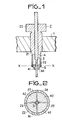
- Fig. 2 is a sectional view along XX (see fig. 1) of the tuning device. This view shows the movable rod 3 which, by the I of the four stic blades, marked 25 to 28, constituting the end 22 of the clamp, is clamped between the jaws of the clamp. These jaws are formed by the four sections of the split ring which were discussed during the description of FIG. 1; they are designated by the references 40 to 43 in FIG. 2.
- the insert (40, 41 in FIG. 1), making contact can be produced not only in silver but in any other metal or alloy which is a good conductor of electricity and relatively malleable so as to be able to wearing out, matching the shape of the sliding surface against which it comes into contact; this is the break-in that was discussed earlier.
- this insert is of dimensions clearly greater than the surface of the sliding contact which it must provide, it is possible to produce it by assembling two metal parts: a metal part which is good conductor of surface currents and relatively malleable, at the place of sliding contact, and another metal part for which the choice of metal no longer has to be guided by considerations of electrical conductivity.
Description
La présente invention se rapporte à un dispositif d'accord en hyperfréquences comportant une partie fixe par rapport à la paroi d'une cavité et une partie mobile coulissant à l'intérieur de la partie fixe de manière à pouvoir pénétrer plus ou moins profondément dans la cavité; un contact éléctrique de bonne qualité entre la pièce fixe et la pièce mobile doit assurer le passage des courant de surface entre ces deux pièces.The present invention relates to a microwave tuning device comprising a part fixed relative to the wall of a cavity and a movable part sliding inside the fixed part so as to be able to penetrate more or less deeply into the cavity; good quality electrical contact between the fixed part and the moving part must ensure the passage of surface currents between these two parts.
De tels dispositifs sont connus, par exemple par le brevet US 25 56 607, dans lesquels des lames élastiques solidaires de l'une des parties assurent un contact glissant avec l'autre partie. Ces lames sont réalisées en des matériaux présentant une bonne élasticité mais sont, de ce fait, dures, fragiles, abrasives et conduisent mal l'électricité. Pour remédier à ces défauts, il est connu de recouvrir ces lames élastiques d'un dépôt d'argent ou d'or réalisé par électrolyse, qui constitue un bon conducteur des courants hyperfréquences qui sont des courants de surface. Etant donné que la pièce mobile, pour des raisons de rigidité mécanique, doit être réalisée en un métal dont la dureté est supérieure à celle de l'argent ou de l'or, les déplacements répétés de la pièce mobile à l'intérieur de la pièce fixe, du fait des frottements, amènent une dégradation rapide de l'état de surface, c'est-à-dire du dépôt d'argent ou d'or. C'est le cas, par exemple, lorsqu'un tel dispositif est utilisé dans un filtre »agile en fréquences«, c'est-à-dire dans un filtre destiné à travailler dans plusieurs gammes de fréquences ou canaux et capable de passer rapidement d'une gamme ou d'un canal à l'autre; cette dégradation rapide de l'état de surface entraîne d'une part une diminution progressive de la qualité du filtre, avec, en particulier, une augmentation des pertes et l'apparition de »crachements« lors des changements d'accord et d'autre part une durée de vie limitée.Such devices are known, for example from patent US 25 56 607, in which elastic blades integral with one of the parts ensure sliding contact with the other part. These blades are made of materials with good elasticity but are therefore hard, fragile, abrasive and poorly conduct electricity. To remedy these defects, it is known to cover these elastic strips with a deposit of silver or gold produced by electrolysis, which constitutes a good conductor of the microwave currents which are surface currents. Since the moving part, for reasons of mechanical rigidity, must be made of a metal whose hardness is greater than that of silver or gold, the repeated movements of the moving part inside the fixed part, due to friction, lead to a rapid deterioration of the surface condition, that is to say the deposit of silver or gold. This is the case, for example, when such a device is used in a “frequency agile” filter, that is to say in a filter intended to work in several frequency ranges or channels and capable of passing quickly. from one range or channel to another; this rapid deterioration of the surface condition leads on the one hand to a progressive reduction in the quality of the filter, with, in particular, an increase in losses and the appearance of "spitting" during changes of chord and on the other hand apart from a limited lifespan.
La présente invention a pour but d'assurer un bon contact électrique entre la partie fixe et la partie mobile du dispositif et ce, même quand la partie mobile se déplace.The object of the present invention is to ensure good electrical contact between the fixed part and the mobile part of the device, even when the mobile part is moving.
Un dispositif d'accord en hyperfréquences selon l'invention, tel qu'il est décrit dans la revendication 1 ci-jointe, permet d'atteindre ce but. Il s'agit d'un dispositif d'accord comportant une tige cylindrique mobile ayant une surface de glissement et une pièce cylindrique creuse, fixée à une paroi d'une cavité, qu'elle traverse, et terminée, vers son extrémité située dans la cavité, par n pièces élastiques (n entier au moins égal à 2) et à l'intérieur de laquelle glisse la tige en la traversant de part en part pour pénétrer d'une longueur réglable dans la cavité, les pièces élastiques appuyant sur la surface de glissement des contacts; ce dispositif est principalement caractérisé en ce que n fentes longitudinales sont pratiquées dans l'extrémité de la pièce cylindrique située dans la cavité et en ce que les pièces élastiques comportent: les n lames de la pièce cylindrique comprises entre les n fentes et n pièces rapportées constituant des mors, en métal bon conducteur de l'électricité, associées respectivement aux n lames et formant les contacts.A microwave tuning device according to the invention, as described in claim 1 attached, achieves this goal. It is a tuning device comprising a movable cylindrical rod having a sliding surface and a hollow cylindrical part, fixed to a wall of a cavity, which it crosses, and completed, towards its end situated in the cavity, by n elastic parts (n integer at least equal to 2) and inside which the rod slides, crossing it right through to penetrate an adjustable length into the cavity, the elastic parts pressing on the surface sliding contacts; this device is mainly characterized in that n longitudinal slots are formed in the end of the cylindrical part located in the cavity and in that the elastic parts comprise: the n blades of the cylindrical part comprised between the n slots and n added parts constituting jaws, of metal which is a good conductor of electricity, associated respectively with the n blades and forming the contacts.
Les avantages apportés par le dispositif d'accord selon l'invention consistent principalement dans un meilleur fonctionnement et une plus longue durée de vie du matériel.The advantages provided by the tuning device according to the invention mainly consist in a better functioning and a longer life of the equipment.
Il est par ailleurs à noter qu'il est également connu, par le brevet US 25 61 727, un dispositif d'accord d'une triode dans lequel une pièce cylindrique creuse comporte une extrémité fendue longitudinalement pour former des lames élastiques sur lesquelles sont rapportés des contacts. Cette pièce cylindrique creuse est mobile; elle traverse une paroi de la triode pour venir entourer, par son extrémité munie de lames, l'anode de la triode qui est solidaire de la paroi opposée. Mais ce dispositif ne perment pas le réglage de la pénétration d'une tige d'accord dans une cavité puisque l'anode de la triode qui pourrait être assimilée à une tige est fixe et est solidaire d'une paroi opposée à celle que traverse la pièce cylindrique creuse et que, de plus, l'anode ne traverse pas de part en part la pièce cylindrique creuse.It should also be noted that it is also known, from US
La présente invention sera mieux comprise et d'autres caractéristiques apparaîtront à l'aide de la description ci-après et des figures s'y rapportant qui représentent,
- - la fig. 1 une vue partielle, en coupe, d'un filtre comportant un dispositif selon l'invention,
- - la fig. 2 une vue en coupe du dispositif représenté sur la fig. 1.
- - fig. 1 is a partial view, in section, of a filter comprising a device according to the invention,
- - fig. 2 a sectional view of the device shown in FIG. 1.
La fig. 1 est une vue partielle, en coupe, d'un filtre »agile en fréquences«. La fig. 1 montre la paroi 1, d'une cavité. Cette paroi est percée d'un trou cylindrique, de diamètre 11 mm, dans lequel est emmanché un dispositif d'accord; ce dispositif d'accord comporte une pièce cylindrique creuse 2, formant pince; à l'intérieur de cette pince coulisse une tige cylindrique, plein, 3, en laiton.Fig. 1 is a partial view, in section, of an “frequency agile” filter. Fig. 1 shows the wall 1 of a cavity. This wall is pierced with a cylindrical hole, 11 mm in diameter, into which is fitted a tuning device; this tuning device comprises a hollow
La pince 2 comporte une tête cylindrique, 20, de diamètre extérieur 20 mm, extérieure à la cavité, une partie médiane 21 du diamètre du trou percé dans la paroi de la cavité et une partie terminale 22 constituée par un cylindre de diamètre extérieur 9 mm. Alors que la tête 20 et la partie médiane 21 ont une épaisseur de paroi importante, la partie terminale 22 est un cylindre creux à paroi mince, qui est fendun longitudinalement sur une longueur AB, selon quatre fentes parallèles, à 90° les unes des autres; la pince 2 est en bronze au béryllium et, grâce à un traitement qui sera décrit plus loin, les quatre lames déterminées par les quatre fentes sont rendues élastiques.The
Dans les dispositifs classiques ces lames élastiques sont recouvertes d'un dépôt d'argent ou d'or et appuient directement sur la tige cylindrique; comme il a été indiqué plus haut les frottements dus aux déplacements de la tige, entraînement une usure rapide du revêtement d'argent ou d'or et finalement la mise hors d'usage du filtre.In conventional devices these elas blades ticks are covered with a deposit of silver or gold and press directly on the cylindrical rod; as indicated above, the friction due to displacements of the rod, entrainment rapid wear of the coating of silver or gold and finally putting the filter out of use.
Comme le montre la fig. 1 des pièces rapportées, telles que 40, 41, sont intercalées entre les lames élastiques et la tige 3; ces pièces rapportées, réalisées en argent, sond solidaires des lames élastiques et viennent en contact avec la tige 3.As shown in fig. 1 of the inserts, such as 40, 41, are interposed between the elastic blades and the
La pince 2 est farbriquée comme suit. Une ébauche en bronze au béryllium est réalisée qui est reprise mécaniquement pour atteindre les cotes désirées en particulier en ce qui concerne le diamètre extérieur de la partie médiane. Un anneau en argent est rendu solidaire, par brasage, de l'extrémité libre de la partie terminale 22 de la pince 2. La partie teminale est alors sciée à l'aide d'une fraise-scie très fine donnant une largeur de fente de 3/10 8 de millimètre. Un conformateur, constitué par un axe de centrage cylindrique de diamètre 1,6 mm est introduit dans le trou de la bague fendue où coulissera la tige 3. Il est à noter que le diamètre de ce conformateur est légèrement inférieur au diamètre de la partie de la tige 3 qui coulissera dans la pince 2 de manière à assurer, par la suite, un bon serrage de la tige entre les extrémités de la pince. Un cerclage, réalisé à l'aide d'une bande métallique, perment de maintenir les extrémités de la pince 2 en contact avec le conformateur. L'ensemble constitué par la pince 2, le conformateur et la bande de cerclage est introduit pendant deux heures dans une enceinte à 320° C; ce traitement thermique classique est destiné à donner aux lames de la pince 2 l'élasticité voulue. La pince est ensuite recouverte, par électrolyse, d'un dépôt d'argent d'une épaisseur de 7 microns.The
Ainsi réalisée la pince ne risque pas, par une usure rapide au niveau des contacts glissants, d'entraîner la mise hors d'usage du dispositif d'accord. En effet, l'usure admissible au niveau des contacts n'est plus de quelques microns comme avec les dispositifs classiques où, sous les quelques microns d'épaisseur du dépôt électrolytique d'argent l'usure fait apparaître, à l'extrémité de la pince en contact avec la tige, un métal mauvais conducteur; cette usure admissible est maintenant de quelques dizièmes de millimètre. De plus il est à remarquer que l'usure de l'argent des pièces rapportées, telles que 40, 41, sur le laiton de la tige 3 réalise un rodage du dispositif d'accord et améliore donc son fonctionnement; au contraire dans les dispositifs classiques ne comportant pas de pièces rapportées l'usure de l'argent qui n'est là que sous forme d'un dépôt électrolytique mince, a tendance à former des copeaux préjudicables au bon fonctionnement du dispositif.Thus produced the clamp does not risk, by rapid wear at the level of the sliding contacts, to cause the disabling of the tuning device. In fact, the admissible wear at the level of the contacts is no longer a few microns as with conventional devices where, under the few microns of thickness of the electrolytic deposit of silver, wear shows at the end of the clamp in contact with the rod, a bad conductive metal; this allowable wear is now a few tenths of a millimeter. In addition, it should be noted that the wear of the silver of the added parts, such as 40, 41, on the brass of the
La fig. 2 est une vue en coupe selon XX (voir fig. 1) du dispositif d'accord. Cette vue montre la tige mobile 3 qui, par le je des quatre lames stiques, repérées 25 à 28, constituant l'extrémité 22 de la pince, est serrée entre les mors de la pince. Ces mors sont constitués par les quatre sections de l'anneau fendu dont il a été question lors de la description de la fig. 1; ils sont désignés par les repères 40 à 43 sur la fig. 2.Fig. 2 is a sectional view along XX (see fig. 1) of the tuning device. This view shows the
Il est à noter que la pièce rapportée (40, 41 sur la fig 1), faisant contact, peut être réalisée non seulement en argent mais en tout autre métal ou alliage bon conducteur de l'électricité et relativement malléable de manière à pouvoir, en s'usant, épouser la forme de la surface de glissement contre laquelle elle vient en contact; c'est le rodage dont il a été question plus avant. De plus, quand cette pièce rapportée est de dimensions nettement supérieures à la surface du contact glissant qu'elle doit assurer, il est possible de la réaliser par assemblage de deux parties métalliques: une partie métallique bonne conductrice des courants de surface et relativement malléable, à l'endroit du contact glissant, et une autre partie métallique pour laquelle de choix du métal n'a plus à être guidé par des considérations de conductibilité électrique.It should be noted that the insert (40, 41 in FIG. 1), making contact, can be produced not only in silver but in any other metal or alloy which is a good conductor of electricity and relatively malleable so as to be able to wearing out, matching the shape of the sliding surface against which it comes into contact; this is the break-in that was discussed earlier. In addition, when this insert is of dimensions clearly greater than the surface of the sliding contact which it must provide, it is possible to produce it by assembling two metal parts: a metal part which is good conductor of surface currents and relatively malleable, at the place of sliding contact, and another metal part for which the choice of metal no longer has to be guided by considerations of electrical conductivity.
Claims (3)
Applications Claiming Priority (2)
| Application Number | Priority Date | Filing Date | Title |
|---|---|---|---|
| FR8004949 | 1980-03-05 | ||
| FR8004949A FR2477782A1 (en) | 1980-03-05 | 1980-03-05 | HYPERFREQUENCY TUNING DEVICE OF THE SLIDING CONTACTS TYPE AND FILTER COMPRISING SUCH A DEVICE |
Publications (2)
| Publication Number | Publication Date |
|---|---|
| EP0035440A1 EP0035440A1 (en) | 1981-09-09 |
| EP0035440B1 true EP0035440B1 (en) | 1984-05-16 |
Family
ID=9239343
Family Applications (1)
| Application Number | Title | Priority Date | Filing Date |
|---|---|---|---|
| EP81400287A Expired EP0035440B1 (en) | 1980-03-05 | 1981-02-24 | Sliding-contact type microwave tuning system |
Country Status (5)
| Country | Link |
|---|---|
| US (1) | US4376923A (en) |
| EP (1) | EP0035440B1 (en) |
| JP (1) | JPS56136002A (en) |
| DE (1) | DE3163570D1 (en) |
| FR (1) | FR2477782A1 (en) |
Families Citing this family (7)
| Publication number | Priority date | Publication date | Assignee | Title |
|---|---|---|---|---|
| GB8323143D0 (en) * | 1983-08-27 | 1983-09-28 | Oxley R F | Tuning screw |
| FI89115C (en) * | 1991-09-18 | 1993-08-10 | Lk Products Oy | FOERFARANDE FOER FAESTANDET AV EN RESONATORSTAV MOT ETT HOEGFREKVENSFILTERS VAEGG OCH HOEGFREKVENSFILTER |
| GB2308235B (en) * | 1995-12-12 | 1999-11-24 | Eev Ltd | High frequency apparatus |
| DE19707153A1 (en) * | 1997-02-22 | 1998-08-27 | Philips Patentverwaltung | Microwave device |
| US6104263A (en) * | 1997-05-28 | 2000-08-15 | Hewlett-Packard Company | Capacitive tuning screw having a compressible tip |
| US8269582B2 (en) * | 2009-10-30 | 2012-09-18 | Alcatel Lucent | Tuning element assembly and method for RF components |
| KR102422720B1 (en) * | 2017-05-02 | 2022-07-20 | 주식회사 케이엠더블유 | Cavity type radio frequency filter |
Citations (3)
| Publication number | Priority date | Publication date | Assignee | Title |
|---|---|---|---|---|
| US2556607A (en) * | 1946-07-27 | 1951-06-12 | Hazeltine Research Inc | Wave-signal translating arrangement |
| US2561727A (en) * | 1943-07-07 | 1951-07-24 | Harold G Cooper | Tuning of electrical resonators |
| US2790151A (en) * | 1952-01-05 | 1957-04-23 | Henry J Riblet | Temperature compensated cavity resonator |
Family Cites Families (1)
| Publication number | Priority date | Publication date | Assignee | Title |
|---|---|---|---|---|
| DE1280996B (en) * | 1967-07-14 | 1968-10-24 | Telefunken Patent | Tuning device for the cavity of a microwave component |
-
1980
- 1980-03-05 FR FR8004949A patent/FR2477782A1/en active Granted
-
1981
- 1981-02-24 DE DE8181400287T patent/DE3163570D1/en not_active Expired
- 1981-02-24 EP EP81400287A patent/EP0035440B1/en not_active Expired
- 1981-03-04 JP JP3108381A patent/JPS56136002A/en active Granted
- 1981-03-04 US US06/240,286 patent/US4376923A/en not_active Expired - Fee Related
Patent Citations (3)
| Publication number | Priority date | Publication date | Assignee | Title |
|---|---|---|---|---|
| US2561727A (en) * | 1943-07-07 | 1951-07-24 | Harold G Cooper | Tuning of electrical resonators |
| US2556607A (en) * | 1946-07-27 | 1951-06-12 | Hazeltine Research Inc | Wave-signal translating arrangement |
| US2790151A (en) * | 1952-01-05 | 1957-04-23 | Henry J Riblet | Temperature compensated cavity resonator |
Also Published As
| Publication number | Publication date |
|---|---|
| FR2477782B1 (en) | 1983-12-23 |
| JPS56136002A (en) | 1981-10-23 |
| US4376923A (en) | 1983-03-15 |
| FR2477782A1 (en) | 1981-09-11 |
| JPS6153887B2 (en) | 1986-11-19 |
| EP0035440A1 (en) | 1981-09-09 |
| DE3163570D1 (en) | 1984-06-20 |
Similar Documents
| Publication | Publication Date | Title |
|---|---|---|
| EP0148088B1 (en) | Flexible metallic gasket comprising vanishing protuberances | |
| EP0035440B1 (en) | Sliding-contact type microwave tuning system | |
| EP0662736B1 (en) | Rotating electrical slipring with multiwire brushes | |
| EP1576696A1 (en) | Small-volume antenna, in particular for portable telephones | |
| EP1586122B1 (en) | Photovoltaic module comprising external connector pins | |
| EP1202299A1 (en) | Electrical energy accumulating device consisting of wound strips and its manufacturing method | |
| WO1992004746A1 (en) | Female connector with double-strip contacts | |
| FR2516711A1 (en) | Self-stripping and clamping terminal for insulated wire - has bevelled-edge slit which cuts through insulation when wire is forced into it by sliding action | |
| CA2138358A1 (en) | Metallic foam-support electrode plate for electrochemical generator and fabrication process of the same | |
| FR2604026A1 (en) | CIRCUIT BREAKER HAVING AN IMPROVED ARC EXTINGUISHING STRUCTURE | |
| EP0241331B1 (en) | Process for making an electrically conductive pattern on the non-developable surface of an insulating substrate and device obtained | |
| FR2558996A1 (en) | FREQUENCY MULTIPLIER FOR MILLIMETER WAVES | |
| EP0068919B1 (en) | Microwave resonator of the variable capacitor type, comprising dielectric material | |
| FR2971892A1 (en) | ELECTRICAL CONTACT AND CONNECTOR ASSEMBLY HAS A NUMBER OF MANEUVER | |
| CA1080795A (en) | Sparking device in gas medium | |
| EP0038243B1 (en) | Profiled metallic bar for producing a conductive element, method for producing the element, and the element so produced | |
| WO2005029649A2 (en) | Connection device for electrical conductor panels | |
| EP0117804A1 (en) | Manufacturing method of a microwave cavity, and cavity obtained thereby | |
| FR2504311A1 (en) | Repetitive make=and=break switch with silver contacts - of spherical and plane forms allowing compensatory metal transfer and criss=crossed pattern of furrows | |
| FR2690367A1 (en) | Device for positioning a tool or a workpiece on a machine tool | |
| FR2519186A1 (en) | Contactor with high degree of insulation for polyphase currents - has exterior compartment walls connected by elements aligned along plane of symmetry from which they are separated by ridges | |
| FR2504318A1 (en) | Brush unit for multi-segment electric motor commutator - is formed by successive operations on double metal strip and minimises material wastage | |
| FR2918505A1 (en) | COAXIAL ATTENUATOR | |
| FR2474239A1 (en) | ELECTRONIC LENSES FOR ELECTRON CANNONS, ESPECIALLY FOR TELEVISION IMAGE TUBES | |
| EP0531222A1 (en) | Process for making a contact carrying blade of a switch by cutting a band and blade made by this process |
Legal Events
| Date | Code | Title | Description |
|---|---|---|---|
| PUAI | Public reference made under article 153(3) epc to a published international application that has entered the european phase |
Free format text: ORIGINAL CODE: 0009012 |
|
| AK | Designated contracting states |
Designated state(s): DE GB IT |
|
| 17P | Request for examination filed |
Effective date: 19820206 |
|
| ITF | It: translation for a ep patent filed |
Owner name: JACOBACCI & PERANI S.P.A. |
|
| GRAA | (expected) grant |
Free format text: ORIGINAL CODE: 0009210 |
|
| AK | Designated contracting states |
Designated state(s): DE GB IT |
|
| REF | Corresponds to: |
Ref document number: 3163570 Country of ref document: DE Date of ref document: 19840620 |
|
| PLBE | No opposition filed within time limit |
Free format text: ORIGINAL CODE: 0009261 |
|
| STAA | Information on the status of an ep patent application or granted ep patent |
Free format text: STATUS: NO OPPOSITION FILED WITHIN TIME LIMIT |
|
| 26N | No opposition filed | ||
| PGFP | Annual fee paid to national office [announced via postgrant information from national office to epo] |
Ref country code: GB Payment date: 19891231 Year of fee payment: 10 |
|
| PGFP | Annual fee paid to national office [announced via postgrant information from national office to epo] |
Ref country code: DE Payment date: 19900222 Year of fee payment: 10 |
|
| ITTA | It: last paid annual fee | ||
| PG25 | Lapsed in a contracting state [announced via postgrant information from national office to epo] |
Ref country code: GB Effective date: 19910224 |
|
| GBPC | Gb: european patent ceased through non-payment of renewal fee | ||
| PG25 | Lapsed in a contracting state [announced via postgrant information from national office to epo] |
Ref country code: DE Effective date: 19911101 |