EP0035324B1 - Split axle drive mechanisms - Google Patents
Split axle drive mechanisms Download PDFInfo
- Publication number
- EP0035324B1 EP0035324B1 EP81300460A EP81300460A EP0035324B1 EP 0035324 B1 EP0035324 B1 EP 0035324B1 EP 81300460 A EP81300460 A EP 81300460A EP 81300460 A EP81300460 A EP 81300460A EP 0035324 B1 EP0035324 B1 EP 0035324B1
- Authority
- EP
- European Patent Office
- Prior art keywords
- drive
- shaft
- differential
- split axle
- clutch
- Prior art date
- Legal status (The legal status is an assumption and is not a legal conclusion. Google has not performed a legal analysis and makes no representation as to the accuracy of the status listed.)
- Expired
Links
- 230000007246 mechanism Effects 0.000 title claims description 23
- 230000005540 biological transmission Effects 0.000 description 3
- 230000000295 complement effect Effects 0.000 description 1
- 238000010276 construction Methods 0.000 description 1
- 230000008878 coupling Effects 0.000 description 1
- 238000010168 coupling process Methods 0.000 description 1
- 238000005859 coupling reaction Methods 0.000 description 1
- 230000001360 synchronised effect Effects 0.000 description 1
Images

Classifications
-
- B—PERFORMING OPERATIONS; TRANSPORTING
- B60—VEHICLES IN GENERAL
- B60K—ARRANGEMENT OR MOUNTING OF PROPULSION UNITS OR OF TRANSMISSIONS IN VEHICLES; ARRANGEMENT OR MOUNTING OF PLURAL DIVERSE PRIME-MOVERS IN VEHICLES; AUXILIARY DRIVES FOR VEHICLES; INSTRUMENTATION OR DASHBOARDS FOR VEHICLES; ARRANGEMENTS IN CONNECTION WITH COOLING, AIR INTAKE, GAS EXHAUST OR FUEL SUPPLY OF PROPULSION UNITS IN VEHICLES
- B60K17/00—Arrangement or mounting of transmissions in vehicles
- B60K17/34—Arrangement or mounting of transmissions in vehicles for driving both front and rear wheels, e.g. four wheel drive vehicles
- B60K17/348—Arrangement or mounting of transmissions in vehicles for driving both front and rear wheels, e.g. four wheel drive vehicles having differential means for driving one set of wheels, e.g. the front, at one speed and the other set, e.g. the rear, at a different speed
- B60K17/35—Arrangement or mounting of transmissions in vehicles for driving both front and rear wheels, e.g. four wheel drive vehicles having differential means for driving one set of wheels, e.g. the front, at one speed and the other set, e.g. the rear, at a different speed including arrangements for suppressing or influencing the power transfer, e.g. viscous clutches
Definitions
- This invention relates to split axle drive mechanisms as specified in the preamble of claim 1, for example as disclosed in US-A-2 913 929.
- a common drive configuration for a part-time four-wheel drive vehicle comprises a transfer case having an input shaft driven by the vehicle transmission, and two output shafts.
- One output shaft is drive-connected to the input shaft for continuously driving one set of vehicle wheels, usually the rear wheels, through a propeller shaft, differential and split axle.
- the second output shaft is connectible to the input shaft by a clutch or the like in the transfer case for selectively driving the other set of vehicle wheels, usually the front wheels, through a second propeller shaft, differential and split axle.
- Two-wheel drive is provided when the clutch in the transfer case is disengaged, and four-wheel drive when the clutch is engaged.
- a long-standing problem associated with part-time four-wheel drive configurations of the above-noted type is wear and power consumption in the two-wheel drive mode. This is caused by the non-driven front wheels back- driving the drive line components between the non-driven wheels and the clutch or comparable mechanism in the transfer case which disconnects the second output shaft from the transfer case input shaft.
- Hub locks are either inconvenient to operate (manual hub locks) or expensive and complicated (automatic hub locks).
- the object of the present invention is to achieve an improved solution to the said problem.
- split axle drive mechanism in accordance with the present invention is characterised by the features specified in the characterising portion of claim 1.
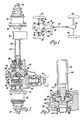
- FIG. 1 a schematic plan view of a part-time four-wheel drive vehicle, comprising engine 10, transmission 12 and transfer case 14 mounted on a vehicle chassis (not shown).
- the engine 10 and transmission 12 are well-known components, as is the transfer case 14, which typically has an input shaft (not shown), a main output shaft 16 and an auxiliary output shaft 18.
- the main output shaft 16 is drive-connected to the input shaft in the transfer case 14 and is customarily aligned with it.
- the auxiliary output shaft 18 is drive connectible to the input shaft by a clutch or the like in the transfer case 14 and customarily offset from it.
- the clutch is actuated by a suitable selector mechanism (not shown) which is generally remotely controlled by the vehicle driver.
- the main output shaft 16 is drivingly connected to a rear propeller shaft 20 which in turn is drivingly connected to a rear differential 22.
- the rear differential 22 drives the rear wheels 24 through split axle parts in a well-known manner.
- the auxiliary output shaft 18 is drivingly connected to a front propeller shaft 26 which in turn is drivingly connected to a split axle drive mechanism 28 for selectively driving the front wheels 30 through split axle parts.
- the split axle drive mechanism 28 includes an automotive-type differential 32 inside a housing 34.
- the differential 32 has a drive shaft 36 and a differential case 38 rotatably mounted in the housing 34 on orthogonally related axes.
- the drive shaft 36 is the differential input and has an external yoke 40 at one end for universally coupling the drive shaft 36 to the front propeller shaft 26.
- the internal end of the drive shaft 36 has an integral driving pinion 42 which meshes with a ring gear 44 attached to the differential case 38.
- the differential case 38 carries a plurality of rotatable pinion gears 46 mounted on a cross pin 48.
- the pinion gears 46 mesh with side gears 50 and 52 which are splined to the ends of the stub shafts 54 and 56 respectively.
- the stub shafts 54 and 56 are rotatably mounted in the housing 34 on the differential case axis. These stub shafts are rotatable relative to each other and to the differential case.
- the differential 32 as thus far described and its mode of operation are well known.
- the split drive axle mechanism 28 further includes a positive clutch 58 which is best shown in Figures 3, 4 and 5.
- the clutch 58 changes the mode of operation of the differential 32 and makes it particularly useful for the selectively driven wheels in a part-time four-wheel drive vehicle.
- the clutch 58 comprises an integral spline wheel 60 at the outer end of the stub shaft 54 and a matching spline wheel 62 attached to the inner end of an extension shaft 64.
- the extension shaft 64 has its inner end journalled in the hollow outer end of the stub shaft 54 and its outer end journalled in a bearing (not shown) at the remote end of an extension tube 66 attached to the housing 34.
- the clutch 58 further includes an internally splined sleeve 68 which is slidably mounted on the spline wheel 60.
- the splined sleeve 68 is shiftable between a disengaged position (shown in solid lines in Figure 3) and an engaged position (shown in phantom lines in Figures 3 and 4) where it couples the spline wheels 60 and 62. (The shifter for operating the clutch 58 will be described in detail later on.)
- the split axle drive mechanism 28 is attached to the vehicle chassis by means of a housing bracket (not shown) and a bracket 70 on the extension tube 66.
- the split axle drive mechanism 28 has two outputs for the respective split axle parts associated with the respective front wheels 30.
- One output is the stub shaft 54, clutch 58 and extension shaft 64 which has an external flange 72 for attaching one of the split axle parts.
- the other output is the stub shaft 56 which has an external flange 74 for attaching the other split axle part.
- Suitable split axle parts are well known from front wheel drive automobiles. These may be used for connecting the split axle drive mechanism 28 to the front wheels 30.
- the drawings schematically illustrate a common type of half shaft for a driving connection to independently suspended steerable vehicle wheels comprising an axle shaft 76 having a plunging universal joint 78 at its inboard end adapted for connection to an output such as the flange 72 or 74 and the well know Rzeppa type universal joint 80 at its outboard end adapted to be connected to the vehicle wheel 30.
- the split axle drive mechanism 28 also includes a shifter 81 for operating the clutch 58.
- the shifter comprises a fork 82 having its tines engaged in an external groove of the sleeve 68 and its base slidably mounted on a slide 84.
- the fork 82 is positioned on the slide 84 by opposed coil springs 86 and 88.
- the slide 84 itself is translated by a push-pull cable 90.
- Figure 4 shows the fork 82 and the slide 84 in the clutch disengaged position.
- the clutch 58 is engaged by moving the slide 84 to the left from the position shown in Figure 4. This loads the spring 88, which in turn biases the fork 82 and sleeve 68 toward the left.
- the sleeve 68 then slides into engagement with the spline wheel 62 under the action of spring 88 when their respective splines align in a complementary manner.
- the clutch 58 is disengaged by returning the slide to the position shown in Figure 4. This loads the spring 86, which in turn returns the slide 84 and fork 82 to the clutch disengaged position when the biasing force of spring 86 is sufficient to overcome the torque load on the engaged splines of spline wheel 62 and sleeve 68.
- the split axle drive mechanism 28 operates as a conventional differential when the clutch 58 is engaged and the vehicle is in the four-wheel drive mode.
- the auxiliary output shaft 18 is drive-connected to the input shaft in the transfer case 14 and it drives the drive shaft 36 (differential input).
- the drive shaft 36 in turn drives the differential case 38, which drives the two differential outputs (stub shaft 54 with the clutched extension shaft 64 and the stub shaft 56) by means of pinion gears 46 and side gears 50 and 52.
- the two differential outputs rotate in unison or at different speeds when necessary in a well-known manner.
- the split axle drive mechanism 28 does back-drive more components than the solution proposed by Anderson (US-A-2 913 929) which is described earlier.
- the pinion gears 46 and side gears 50 and 52 rotate whereas the Anderson pinion gears and side gears do not. But since these gears are not loaded and have a small mass, there is little wear or power consumption caused by the back drive. Any small loss in efficiency is far outweighed by the reduced complexity ahd weight of the mechanism in comparison to the Anderson front axle assembly.
- the auxiliary output shaft 18 is first drive-connected to the input shaft in the transfer case 14. This drives the drive shaft 36 (differential input) and the differential case 38.
- the driven differential case reverses the rotation of the counter-rotating side gear 50 and tends to synchronize the speeds of the side gear 50 and stub shaft 64.
- the clutch 58 is engaged at any vehicle speed by the shifter 81, and both front wheels 30 are driven with the split axle drive mechanism 28 once again acting as a conventional differential.
Landscapes
- Engineering & Computer Science (AREA)
- Chemical & Material Sciences (AREA)
- Combustion & Propulsion (AREA)
- Transportation (AREA)
- Mechanical Engineering (AREA)
- Arrangement And Driving Of Transmission Devices (AREA)
- Arrangement And Mounting Of Devices That Control Transmission Of Motive Force (AREA)
Description
- This invention relates to split axle drive mechanisms as specified in the preamble of claim 1, for example as disclosed in US-A-2 913 929.
- A common drive configuration for a part-time four-wheel drive vehicle comprises a transfer case having an input shaft driven by the vehicle transmission, and two output shafts. One output shaft is drive-connected to the input shaft for continuously driving one set of vehicle wheels, usually the rear wheels, through a propeller shaft, differential and split axle. The second output shaft is connectible to the input shaft by a clutch or the like in the transfer case for selectively driving the other set of vehicle wheels, usually the front wheels, through a second propeller shaft, differential and split axle. Two-wheel drive is provided when the clutch in the transfer case is disengaged, and four-wheel drive when the clutch is engaged.
- A long-standing problem associated with part-time four-wheel drive configurations of the above-noted type is wear and power consumption in the two-wheel drive mode. This is caused by the non-driven front wheels back- driving the drive line components between the non-driven wheels and the clutch or comparable mechanism in the transfer case which disconnects the second output shaft from the transfer case input shaft.
- One well-known solution is the use of a hub lock at each non-driven front wheel to disconnect the wheel from its associated split axle part when two-wheel drive is selected at the transfer case. This solution eliminates back drive of the split axle parts, differential and propeller shaft for the non-driven front wheels as well as the transfer case components ahead of the clutch (or disconnect) in the transfer case. Hub locks, however, are either inconvenient to operate (manual hub locks) or expensive and complicated (automatic hub locks).
- Another solution, which is proposed in the said US-A-2 913 929, involves the use of a front axle assembly having a differential, two clutch units and a rack and pinion device for disconnecting the split axle parts from their associated side gears in the differential. This solution is slightly less efficient than the use of wheel hubs, inasmuch as the split axle parts are still back-driven by the non-driven wheels when two-wheel drive is selected at the transfer case and the clutch units are disengaged by the rack and pinion mechanism.
- The object of the present invention is to achieve an improved solution to the said problem.
- To this end a split axle drive mechanism in accordance with the present invention is characterised by the features specified in the characterising portion of claim 1.
- With this solution, therefore, only one of the split axle parts need be disconnected from its associated side gear in the differential. This solution has significant advantages in cost and weight savings, simplicity of construction, and compactness in design, since one clutch and a complex device for synchronizing the operation of two clutches is eliminated.
- In the accompanying drawings:
- Figure 1 is a schematic plan view of a part-time four-wheel drive vehicle incorporating a split axle drive mechanism in accordance with the invention.
- Figure 2 is a partially sectioned plan view of the split axle drive mechanism shown in Figure 1.
- Figure 3 is an enlargement of a portion of Figure 2.
- Figure 4 is a section taken substantially along the line 4-4 of Figure 3 looking in the direction of the arrows.
- Figure 5 is a section taken substantially along the line 5-5 of Figure 4 looking in the direction of the arrows.
- Referring now to the drawings and particularly Figure 1, there is shown a schematic plan view of a part-time four-wheel drive vehicle, comprising engine 10, transmission 12 and transfer case 14 mounted on a vehicle chassis (not shown). The engine 10 and transmission 12 are well-known components, as is the transfer case 14, which typically has an input shaft (not shown), a
main output shaft 16 and anauxiliary output shaft 18. Themain output shaft 16 is drive-connected to the input shaft in the transfer case 14 and is customarily aligned with it. Theauxiliary output shaft 18 is drive connectible to the input shaft by a clutch or the like in the transfer case 14 and customarily offset from it. The clutch is actuated by a suitable selector mechanism (not shown) which is generally remotely controlled by the vehicle driver. - The
main output shaft 16 is drivingly connected to arear propeller shaft 20 which in turn is drivingly connected to arear differential 22. Therear differential 22 drives the rear wheels 24 through split axle parts in a well-known manner. - The
auxiliary output shaft 18 is drivingly connected to a front propeller shaft 26 which in turn is drivingly connected to a splitaxle drive mechanism 28 for selectively driving thefront wheels 30 through split axle parts. - The invention relates to the split
axle drive mechanism 28 which will now be explained in conjunction with Figures 2 through 5. As shown in Figure 2, the splitaxle drive mechanism 28 includes an automotive-type differential 32 inside a housing 34. Thedifferential 32 has adrive shaft 36 and adifferential case 38 rotatably mounted in the housing 34 on orthogonally related axes. Thedrive shaft 36 is the differential input and has anexternal yoke 40 at one end for universally coupling thedrive shaft 36 to the front propeller shaft 26. The internal end of thedrive shaft 36 has an integral driving pinion 42 which meshes with a ring gear 44 attached to thedifferential case 38. Thedifferential case 38 carries a plurality of rotatable pinion gears 46 mounted on a cross pin 48. The pinion gears 46 mesh withside gears stub shafts 54 and 56 respectively. Thestub shafts 54 and 56 are rotatably mounted in the housing 34 on the differential case axis. These stub shafts are rotatable relative to each other and to the differential case. Thedifferential 32 as thus far described and its mode of operation are well known. - The split
drive axle mechanism 28 further includes apositive clutch 58 which is best shown in Figures 3, 4 and 5. Theclutch 58 changes the mode of operation of thedifferential 32 and makes it particularly useful for the selectively driven wheels in a part-time four-wheel drive vehicle. As disclosed in the drawings, theclutch 58 comprises anintegral spline wheel 60 at the outer end of the stub shaft 54 and a matchingspline wheel 62 attached to the inner end of anextension shaft 64. Theextension shaft 64 has its inner end journalled in the hollow outer end of the stub shaft 54 and its outer end journalled in a bearing (not shown) at the remote end of anextension tube 66 attached to the housing 34. - The
clutch 58 further includes an internallysplined sleeve 68 which is slidably mounted on thespline wheel 60. Thesplined sleeve 68 is shiftable between a disengaged position (shown in solid lines in Figure 3) and an engaged position (shown in phantom lines in Figures 3 and 4) where it couples thespline wheels clutch 58 will be described in detail later on.) - The split
axle drive mechanism 28 is attached to the vehicle chassis by means of a housing bracket (not shown) and abracket 70 on theextension tube 66. - The split
axle drive mechanism 28 has two outputs for the respective split axle parts associated with the respectivefront wheels 30. One output is the stub shaft 54,clutch 58 andextension shaft 64 which has anexternal flange 72 for attaching one of the split axle parts. The other output is thestub shaft 56 which has anexternal flange 74 for attaching the other split axle part. - Suitable split axle parts, commonly referred to as half shafts, are well known from front wheel drive automobiles. These may be used for connecting the split
axle drive mechanism 28 to thefront wheels 30. The drawings schematically illustrate a common type of half shaft for a driving connection to independently suspended steerable vehicle wheels comprising anaxle shaft 76 having a plunginguniversal joint 78 at its inboard end adapted for connection to an output such as theflange universal joint 80 at its outboard end adapted to be connected to thevehicle wheel 30. - The split
axle drive mechanism 28 also includes a shifter 81 for operating theclutch 58. The shifter comprises afork 82 having its tines engaged in an external groove of thesleeve 68 and its base slidably mounted on a slide 84. Thefork 82 is positioned on the slide 84 byopposed coil springs pull cable 90. Figure 4 shows thefork 82 and the slide 84 in the clutch disengaged position. Theclutch 58 is engaged by moving the slide 84 to the left from the position shown in Figure 4. This loads thespring 88, which in turn biases thefork 82 and sleeve 68 toward the left. Thesleeve 68 then slides into engagement with thespline wheel 62 under the action ofspring 88 when their respective splines align in a complementary manner. Theclutch 58 is disengaged by returning the slide to the position shown in Figure 4. This loads thespring 86, which in turn returns the slide 84 andfork 82 to the clutch disengaged position when the biasing force ofspring 86 is sufficient to overcome the torque load on the engaged splines ofspline wheel 62 andsleeve 68. - The split
axle drive mechanism 28 operates as a conventional differential when theclutch 58 is engaged and the vehicle is in the four-wheel drive mode. In this mode theauxiliary output shaft 18 is drive-connected to the input shaft in the transfer case 14 and it drives the drive shaft 36 (differential input). Thedrive shaft 36 in turn drives thedifferential case 38, which drives the two differential outputs (stub shaft 54 with the clutchedextension shaft 64 and the stub shaft 56) by means of pinion gears 46 and side gears 50 and 52. The two differential outputs rotate in unison or at different speeds when necessary in a well-known manner. - For the two-wheel drive mode, the drive to the
auxiliary output shaft 18 is disconnected in the transfer case and the clutch 58 is disengaged by the shifter 81. In this condition, thelower wheel 30 shown in Figure 1 back-drives theside gear 52 but theupper wheel 30 does not back-drive theside gear 50 because the clutch 58 is disengaged. Since the torque load is removed from theside gear 50, theside gear 52 merely counter-rotates theside gear 50 through the pinion gears 46. Hence, there is no back drive to thedifferential case 38, drive shaft 36 (differential input), front propeller shaft 26,auxiliary output shaft 18 and other transfer case components connected to theauxiliary output shaft 18 ahead of the disconnect in the transfer case 14. This mode of operation eliminates the major portion of wear and power consumption which would result from back drive of bothwheels 30. - The split
axle drive mechanism 28 does back-drive more components than the solution proposed by Anderson (US-A-2 913 929) which is described earlier. The pinion gears 46 and side gears 50 and 52 rotate whereas the Anderson pinion gears and side gears do not. But since these gears are not loaded and have a small mass, there is little wear or power consumption caused by the back drive. Any small loss in efficiency is far outweighed by the reduced complexity ahd weight of the mechanism in comparison to the Anderson front axle assembly. - In order to return to the four-wheel drive mode, the
auxiliary output shaft 18 is first drive-connected to the input shaft in the transfer case 14. This drives the drive shaft 36 (differential input) and thedifferential case 38. The driven differential case reverses the rotation of thecounter-rotating side gear 50 and tends to synchronize the speeds of theside gear 50 andstub shaft 64. Once the speeds are synchronous or nearly so, the clutch 58 is engaged at any vehicle speed by the shifter 81, and bothfront wheels 30 are driven with the splitaxle drive mechanism 28 once again acting as a conventional differential. - When changing from four-wheel drive to two-wheel drive it is also preferable to disconnect the
auxiliary output shaft 18 in the transfer case 14 before disengaging the clutch 58 so that the torque load on the clutch 58 is reduced.
Claims (3)
Applications Claiming Priority (2)
| Application Number | Priority Date | Filing Date | Title |
|---|---|---|---|
| US126561 | 1980-03-03 | ||
| US06/126,561 US4341281A (en) | 1980-03-03 | 1980-03-03 | Split axle drive mechanism |
Publications (3)
| Publication Number | Publication Date |
|---|---|
| EP0035324A2 EP0035324A2 (en) | 1981-09-09 |
| EP0035324A3 EP0035324A3 (en) | 1983-01-26 |
| EP0035324B1 true EP0035324B1 (en) | 1985-07-31 |
Family
ID=22425510
Family Applications (1)
| Application Number | Title | Priority Date | Filing Date |
|---|---|---|---|
| EP81300460A Expired EP0035324B1 (en) | 1980-03-03 | 1981-02-04 | Split axle drive mechanisms |
Country Status (7)
| Country | Link |
|---|---|
| US (1) | US4341281A (en) |
| EP (1) | EP0035324B1 (en) |
| JP (2) | JPS56135320A (en) |
| AU (1) | AU534652B2 (en) |
| BR (1) | BR8101193A (en) |
| CA (1) | CA1140363A (en) |
| DE (1) | DE3171525D1 (en) |
Families Citing this family (46)
| Publication number | Priority date | Publication date | Assignee | Title |
|---|---|---|---|---|
| US4452331A (en) * | 1980-11-13 | 1984-06-05 | American Motors Corporation | Vehicle axle |
| USRE31981E (en) * | 1981-05-29 | 1985-09-10 | General Motors Corporation | Control system for split axle drive mechanism |
| US4407387A (en) * | 1981-05-29 | 1983-10-04 | General Motors Corporation | Control system for split axle drive mechanism |
| JPS5880326U (en) * | 1981-11-28 | 1983-05-31 | いすゞ自動車株式会社 | Vehicle power transmission mechanism |
| JPS58136828U (en) * | 1982-03-10 | 1983-09-14 | スズキ株式会社 | Four-wheel drive vehicle drive system |
| IT1161502B (en) * | 1983-07-13 | 1987-03-18 | Fiat Auto Spa | IMPROVEMENTS IN TRANSMISSION SYSTEMS FOR FOUR-WHEEL MOTOR VEHICLES |
| JPS6047630U (en) * | 1983-09-12 | 1985-04-03 | ダイハツ工業株式会社 | Rear wheel drive shaft support structure for four-wheel drive vehicles |
| BR8305573A (en) * | 1983-10-10 | 1985-05-14 | Avm Auto Equip | IMPROVEMENT IN OPTIONAL VEHICLE TRACTION WHEEL RELEASE DEVICE |
| JPS60226326A (en) * | 1984-04-23 | 1985-11-11 | Daihatsu Motor Co Ltd | Four wheel drive vehicle |
| JPS60236840A (en) * | 1984-05-10 | 1985-11-25 | Suzuki Motor Co Ltd | Axle power shifting device for vehicle |
| JPS60183629U (en) * | 1984-05-17 | 1985-12-05 | ヤンマー農機株式会社 | Wheel drive device for riding rice transplanter |
| JPS619329U (en) * | 1984-06-22 | 1986-01-20 | 富士重工業株式会社 | Part-time four-wheel drive vehicle power transmission system |
| JPS6159439U (en) * | 1984-09-27 | 1986-04-22 | ||
| US4625584A (en) * | 1984-11-05 | 1986-12-02 | Toyota Jidosha Kabushiki Kaisha | Split axle drive mechanism for part-time four-wheel drive vehicle |
| JPS61130646A (en) * | 1984-11-29 | 1986-06-18 | Toyota Motor Corp | Differential gear system |
| JPH0637141B2 (en) * | 1985-01-30 | 1994-05-18 | スズキ株式会社 | Two-wheel / four-wheel drive switching device |
| JPS61207219A (en) * | 1985-03-12 | 1986-09-13 | Toyota Motor Corp | Power distributor for vehicles |
| JPS6330571Y2 (en) * | 1985-05-31 | 1988-08-16 | ||
| BR8600514A (en) * | 1986-02-06 | 1987-09-01 | Avm Auto Equip | IMPROVEMENT IN OPTIONAL VEHICLE TRACTION WHEEL RELEASE DEVICE |
| JPH056180Y2 (en) * | 1986-03-03 | 1993-02-17 | ||
| US4699235A (en) * | 1986-03-24 | 1987-10-13 | General Motors Corporation | Linear actuator control system for split axle drive mechanism |
| JPH053810Y2 (en) * | 1986-11-04 | 1993-01-29 | ||
| JPS63110128U (en) * | 1987-01-12 | 1988-07-15 | ||
| DE3733153A1 (en) * | 1987-10-01 | 1989-04-13 | Man Nutzfahrzeuge Gmbh | DEVICE FOR SELECTIVELY SWITCHING ON AND OFF THE TORQUE FLOW ON THE SHAFT OF DRIVEN MOTOR VEHICLE WHEELS |
| US4907470A (en) * | 1989-08-02 | 1990-03-13 | Deere & Company | Differential housing support |
| US5105900A (en) * | 1990-12-07 | 1992-04-21 | New Venture Gear, Inc. | Transfer case cold shift assist |
| US5105902A (en) * | 1990-12-07 | 1992-04-21 | New Venture Gear, Inc. | Transfer case shift-on-fly system |
| US5162026A (en) * | 1991-02-25 | 1992-11-10 | Dana Corporation | Planetary axle drive system |
| DE4113128C2 (en) * | 1991-04-22 | 1995-05-24 | Steyr Daimler Puch Ag | Claw clutch |
| US5176591A (en) * | 1991-12-19 | 1993-01-05 | Dana Corporation | Planetary gear differential with disconnect |
| JPH05317278A (en) * | 1992-05-26 | 1993-12-03 | Suzuken:Kk | Radio transmission type bioinformation detecting and recording device |
| US5429221A (en) * | 1993-06-07 | 1995-07-04 | Ford Motor Company | All-wheel drive free-wheel mechanism for a motor vehicle |
| US5542515A (en) * | 1994-04-08 | 1996-08-06 | Ford Motor Company | Device for controlling a part-time drive axle for a motor vehicle |
| US5806371A (en) * | 1996-07-23 | 1998-09-15 | American Axle & Manufacturing, Inc. | Gear arrangement with backlash adjustment |
| US5839986A (en) * | 1996-07-23 | 1998-11-24 | Tochigi Fuji Sangyo Kabushiki Kaisha | Differential device with disconnect |
| USRE39054E1 (en) | 1997-04-25 | 2006-04-04 | Aisin Seiki Kabushiki Kaisha | Vehicle drive system including drive mode-shifting mechanism for shifting between two-wheel drive and four-wheel drive |
| US6079539A (en) * | 1999-02-16 | 2000-06-27 | Dana Corporation | In-line axle disconnect assembly |
| JP4461582B2 (en) | 1999-07-14 | 2010-05-12 | アイシン精機株式会社 | Driving force switching mechanism |
| JP4552341B2 (en) * | 2001-03-26 | 2010-09-29 | アイシン精機株式会社 | Differential equipment for four-wheel drive vehicles |
| US6517462B2 (en) | 2001-05-11 | 2003-02-11 | Spicer Technology, Inc. | Dual disconnect drive assembly |
| US20030047402A1 (en) | 2001-09-13 | 2003-03-13 | Borgen Wayne Lee | Dual disconnect drive assembly |
| US7018317B2 (en) * | 2003-05-07 | 2006-03-28 | Arctic Cat Inc. | Recreational vehicle locking differential |
| JP5064043B2 (en) * | 2007-01-25 | 2012-10-31 | 本田技研工業株式会社 | Vehicle drive device |
| US20080256914A1 (en) * | 2007-04-23 | 2008-10-23 | Ricketts Jonathan E | Method and device for automatically coupling a combine feeder interface and a combine header via a stationary gearbox |
| JP2012193780A (en) | 2011-03-15 | 2012-10-11 | Gkn Driveline Japan Ltd | Power interrupting apparatus |
| US9574662B2 (en) * | 2013-12-16 | 2017-02-21 | Hyundai Wia Corporation | Disconnector for hybrid vehicle |
Family Cites Families (12)
| Publication number | Priority date | Publication date | Assignee | Title |
|---|---|---|---|---|
| US3123169A (en) * | 1964-03-03 | Four wheel drive vehicle with automatic wheel | ||
| US1139853A (en) * | 1908-05-23 | 1915-05-18 | Enterprize Automobile Company | Motor-vehicle. |
| US1201232A (en) * | 1916-07-29 | 1916-10-17 | Thomas C Archer | Four-wheel drive for vehicles. |
| US1440341A (en) * | 1921-11-17 | 1922-12-26 | Clarence C Crispen | Differential |
| US2770150A (en) * | 1953-08-07 | 1956-11-13 | Frank E Culverwell | Front axle |
| US2913929A (en) * | 1957-10-07 | 1959-11-24 | Martin E Anderson | Selective drive differential gear and operating mechanism therefor |
| US3058558A (en) * | 1959-09-01 | 1962-10-16 | Allis Chalmers Mfg Co | Coupling mechanism |
| FR1389569A (en) * | 1964-01-07 | 1965-02-19 | Marmon Bocquet | Multipurpose vehicle |
| GB1138942A (en) * | 1965-01-23 | 1969-01-01 | Ferguson Res Ltd Harry | Improvements in or relating to four-wheel drive motor vehicles |
| JPS517628A (en) * | 1974-07-10 | 1976-01-22 | Tochigi Fuji Sangyo Kk | 4 rinkudosha |
| JPS603082B2 (en) * | 1976-08-25 | 1985-01-25 | カネボウ株式会社 | Manufacturing method of heavy metal adsorbent |
| JPS6423330A (en) * | 1987-07-20 | 1989-01-26 | Hitachi Ltd | Logic operation circuit |
-
1980
- 1980-03-03 US US06/126,561 patent/US4341281A/en not_active Expired - Lifetime
- 1980-10-31 CA CA000363732A patent/CA1140363A/en not_active Expired
-
1981
- 1981-02-04 EP EP81300460A patent/EP0035324B1/en not_active Expired
- 1981-02-04 DE DE8181300460T patent/DE3171525D1/en not_active Expired
- 1981-02-10 AU AU67151/81A patent/AU534652B2/en not_active Expired
- 1981-02-26 BR BR8101193A patent/BR8101193A/en not_active IP Right Cessation
- 1981-03-03 JP JP2948481A patent/JPS56135320A/en active Granted
-
1990
- 1990-05-28 JP JP2135545A patent/JPH0328026A/en active Pending
Also Published As
| Publication number | Publication date |
|---|---|
| EP0035324A3 (en) | 1983-01-26 |
| AU6715181A (en) | 1981-09-10 |
| BR8101193A (en) | 1981-09-08 |
| AU534652B2 (en) | 1984-02-09 |
| JPH0123330B2 (en) | 1989-05-02 |
| DE3171525D1 (en) | 1985-09-05 |
| JPH0328026A (en) | 1991-02-06 |
| JPS56135320A (en) | 1981-10-22 |
| CA1140363A (en) | 1983-02-01 |
| EP0035324A2 (en) | 1981-09-09 |
| US4341281A (en) | 1982-07-27 |
Similar Documents
| Publication | Publication Date | Title |
|---|---|---|
| EP0035324B1 (en) | Split axle drive mechanisms | |
| US4407387A (en) | Control system for split axle drive mechanism | |
| US5334116A (en) | All wheel drive transfer case having two wheel overdrive | |
| US4422520A (en) | Transmission apparatus for four-wheel drive motor vehicle | |
| US4779698A (en) | Split axle drive mechanism for part-time four-wheel drive vehicle | |
| US5997428A (en) | Vehicle drive system including drive mode-shifting mechanism for shifting between two-wheel drive and four-wheel drive | |
| US2770150A (en) | Front axle | |
| US4878399A (en) | Planetary sub-transmission | |
| US4289213A (en) | Angular output transfer case | |
| US4645029A (en) | Four-wheel vehicle drive system | |
| US4582160A (en) | Constant four wheel drive vehicle transaxle | |
| JPS629056B2 (en) | ||
| US4194586A (en) | Geared torque selector | |
| US3262512A (en) | Four wheel drive | |
| JPS62204034A (en) | Torque transmission gear | |
| US4813290A (en) | Power takeoff for motor vehicle | |
| EP0469128B1 (en) | Gearbox for motor vehicle | |
| US5271478A (en) | Power transmitting system | |
| US4147225A (en) | Vehicle drive system | |
| USRE31981E (en) | Control system for split axle drive mechanism | |
| US4233857A (en) | Multiple speed transmission with auxiliary transfer drive | |
| WO2016022292A1 (en) | Tandem axles with disconnects | |
| EP0480887B1 (en) | A rear axle for transmitting the driving torque to the rear wheels of a motor vehicle with disengageable four-wheel drive | |
| US4635744A (en) | Four-wheel drive automotive vehicle | |
| JPS6237014Y2 (en) |
Legal Events
| Date | Code | Title | Description |
|---|---|---|---|
| PUAI | Public reference made under article 153(3) epc to a published international application that has entered the european phase |
Free format text: ORIGINAL CODE: 0009012 |
|
| AK | Designated contracting states |
Designated state(s): DE FR GB IT SE |
|
| PUAL | Search report despatched |
Free format text: ORIGINAL CODE: 0009013 |
|
| AK | Designated contracting states |
Designated state(s): DE FR GB IT SE |
|
| 17P | Request for examination filed |
Effective date: 19830311 |
|
| ITF | It: translation for a ep patent filed |
Owner name: BARZANO' E ZANARDO ROMA S.P.A. |
|
| GRAA | (expected) grant |
Free format text: ORIGINAL CODE: 0009210 |
|
| AK | Designated contracting states |
Designated state(s): DE FR GB IT SE |
|
| REF | Corresponds to: |
Ref document number: 3171525 Country of ref document: DE Date of ref document: 19850905 |
|
| ET | Fr: translation filed | ||
| PLBE | No opposition filed within time limit |
Free format text: ORIGINAL CODE: 0009261 |
|
| STAA | Information on the status of an ep patent application or granted ep patent |
Free format text: STATUS: NO OPPOSITION FILED WITHIN TIME LIMIT |
|
| 26N | No opposition filed | ||
| ITTA | It: last paid annual fee | ||
| EAL | Se: european patent in force in sweden |
Ref document number: 81300460.3 |
|
| PGFP | Annual fee paid to national office [announced via postgrant information from national office to epo] |
Ref country code: DE Payment date: 19991231 Year of fee payment: 20 |
|
| PGFP | Annual fee paid to national office [announced via postgrant information from national office to epo] |
Ref country code: GB Payment date: 20000131 Year of fee payment: 20 |
|
| PGFP | Annual fee paid to national office [announced via postgrant information from national office to epo] |
Ref country code: SE Payment date: 20000217 Year of fee payment: 20 Ref country code: FR Payment date: 20000217 Year of fee payment: 20 |
|
| PG25 | Lapsed in a contracting state [announced via postgrant information from national office to epo] |
Ref country code: GB Free format text: LAPSE BECAUSE OF EXPIRATION OF PROTECTION Effective date: 20010203 |
|
| PG25 | Lapsed in a contracting state [announced via postgrant information from national office to epo] |
Ref country code: SE Free format text: THE PATENT HAS BEEN ANNULLED BY A DECISION OF A NATIONAL AUTHORITY Effective date: 20010227 |
|
| REG | Reference to a national code |
Ref country code: GB Ref legal event code: PE20 Effective date: 20010203 |
|
| EUG | Se: european patent has lapsed |
Ref document number: 81300460.3 |