EP0035081A2 - A refractometer - Google Patents

A refractometer Download PDF

Info

Publication number
EP0035081A2
EP0035081A2 EP80304784A EP80304784A EP0035081A2 EP 0035081 A2 EP0035081 A2 EP 0035081A2 EP 80304784 A EP80304784 A EP 80304784A EP 80304784 A EP80304784 A EP 80304784A EP 0035081 A2 EP0035081 A2 EP 0035081A2
Authority
EP
European Patent Office
Prior art keywords
light
sample
refraction
timer
container
Prior art date
Legal status (The legal status is an assumption and is not a legal conclusion. Google has not performed a legal analysis and makes no representation as to the accuracy of the status listed.)
Withdrawn
Application number
EP80304784A
Other languages
German (de)
French (fr)
Other versions
EP0035081A3 (en
Inventor
Leonard Allen Hughes
Evan Richard Flavell
Benjamin C. Willman
Current Assignee (The listed assignees may be inaccurate. Google has not performed a legal analysis and makes no representation or warranty as to the accuracy of the list.)
Biovation LLC
Original Assignee
Biovation LLC
Priority date (The priority date is an assumption and is not a legal conclusion. Google has not performed a legal analysis and makes no representation as to the accuracy of the date listed.)
Filing date
Publication date
Application filed by Biovation LLC filed Critical Biovation LLC
Publication of EP0035081A2 publication Critical patent/EP0035081A2/en
Publication of EP0035081A3 publication Critical patent/EP0035081A3/en
Withdrawn legal-status Critical Current

Links

Images

Classifications

    • GPHYSICS
    • G01MEASURING; TESTING
    • G01NINVESTIGATING OR ANALYSING MATERIALS BY DETERMINING THEIR CHEMICAL OR PHYSICAL PROPERTIES
    • G01N21/00Investigating or analysing materials by the use of optical means, i.e. using sub-millimetre waves, infrared, visible or ultraviolet light
    • G01N21/17Systems in which incident light is modified in accordance with the properties of the material investigated
    • G01N21/41Refractivity; Phase-affecting properties, e.g. optical path length
    • G01N21/4133Refractometers, e.g. differential

Definitions

  • THIS INVENTION relates to a refractometer and to a method for measuring the light refraction of liquids.
  • a refractometer which measures the refraction of light in liquid, may be used for measuring the concentration of a dissolved solute.
  • a refractometer may be used in clinical testing of biological specimens. More particularly, a refractometer can be used to determine the specific gravity of urine, and hence the sugar content of the urine.
  • this particular use of a refractometer is an illustrative example, not a limitation. Problems associated with the present practise relating to the measurement of the specific gravity of urine, and hence the sugar content, will now be described.
  • the first method employed a urinometer, a specially calibrated hydrometer.
  • hydrometers One problem with hydrometers was that they required a large volume of the speciment, at least 30-40 ml.
  • the readings obtained were inherently somewhat inaccurate, due to the formation of a meniscus (or curved top line) along the reading column, the reading being done conventionally from the bottom of the meniscus.
  • the urinometer readout was on an analog scale, it was therefore subject to operator error.
  • a second method of determining the specific gravity of urine has employed an American Optical refractometer, a device with the distinct advantage of requiring only two or three drops of specimen.
  • This device has had to be cleaned between each use: this necessity has added considerably to the time required to perform a series of tests.
  • This prior refractor has further required both a high power optical system, and a manual visual alignment, i.e., a knob had to be turned by the operator to align two fine lines to obtain a reading; and, again, this increased the potential for operator error.
  • the present invention seeks to provide a refractometer in which the above described disadvantages are obviated or reduced.
  • a method for determining the concentration of dissolved solids in a liquid sample comprising the steps of: placing a liquid sample to be tested into a hollow prismatic container which is enclosed in an opaque housing, directing a collimated beam of monochromatic light through the filled prismatic container, measuring the refraction of the beam through the sample filled prism, and displaying the measured refraction as a function of the concentration of dissolved solids in the sample.
  • the refraction of the beam is compared with a value corresponding to a predetermined reference refraction.
  • the refractometer has calibrating means for adjusting said differentiating means, said calibrating means comprising: first switch means, an astable timer connected through said first switch means to said control means to actuate testing, said astable timer also being connected to said decade counter to reset said decade counter at the beginning of each period of said astable timer, second switch means connecting the output of said astable timer to actuate and re-actuate said testing duration timer at the beginning of each period of said astable timer, and adjustment means connected to said testing duration timer, said adjustment means controlling the period for which said testing duration timer is set.
  • a preferred digital refractometer in accordance with the present invention accomplishes the foregoing and other objects by providing (1) a monochromatic substantially point source of light, substantially collimated by a lens, (2) a hollow transparent-walled prism for holding a liquid solution to be studied, (3) a three-terminal photosensor several inches away from the prism which, along with associated electronics, provides a means for measuring the amount of displacement of the light beam due to refraction by the solution in the prism, (4) a second photosensor, and (5) control and display electronics.
  • the sequence of operation may be as follows:
  • Additional logic circuitry operates a warning light display so that samples will not be added while liquid is in the prism chamber.
  • a red light may indicate "wait”, and a green light may indicate "ready”.
  • the photosensor is grounded at one end, has a plus voltage terminal at the other end, preferably a regulated +5-volt terminal, and a centre terminal.
  • the voltage of the centre terminal of the photosensor is put into a bridge circuit. Voltage at the centre terminal is half the supply voltage when the light beam falls at this exact centre of the photopotentiometer. Movement of the spot toward the +5-volt terminal gives increasing voltages, while movement in the other direction gives voltages of less than 2.5 volts.
  • the device is quite linear, so that the voltage put into the bridge circuit is directly prop- orational to the amount of light refraction.
  • the bridge output voltage is suitably amplified and is applied continuously to a voltage-to-frequency converter.
  • the voltage at the centre terminal is converted to a digital signal which is passed on to a decade counter, a decoder driver and from there on to display. These components make up an analog-to-digital converter.
  • a digital refractometer 10 includes an enclosing opaque upper housing member 11 which may be made of a single piece of moulded plastics material.
  • the opaque housing member 11 may be shaped to provide an integral funnel 12 through which a sample may be poured into a hollow prism 13.
  • the hollow prism 13 may be removable and the funnel 12 may be replaced by a hinged or sliding opaque lid providing access to the removable prism when open and blocking light when closed during operation.
  • Transparent walls 14 and 15 of the prism 13 may be made of any suitable optical material including, for example, glass, plastics material, and quartz.
  • the third wall 16 need not be transparent, though it can be.
  • the hollow prism 13 is preferably triangular, having one non-optical side wall 16 and two transparent optical side walls 14 and 15 which meet each other at some suitable angle between about 40° and about 55°, to provide a good spread of light over a range of refractions.
  • the prism 13 has an inlet opening 17 at its top, an overflow opening 18 in it side wall 16 disposed approximately two-thirds the height of the prism 13, a floor 19 sloped downwardly from the side wall 16 towards a point 20 along the edge where the two optical side walls 14 and 15 meet, and a drain opening 21 located at approximately the lowermost point of the sloped floor 19.
  • the overflow opening 18 is connected to an overflow tube 22, through which excess sample may be conducted (see Figure 6) to a waste receptacle outside the digital refractometer 10.
  • the drain opening 21 is connected by a drain tube 23 to the inlet side of a solenoid drain valve 24, which remains closed during filling and testing and is then opened automatically to evacuate the hollow prism 13 after the test has been completed.
  • the outlet side of the solenoid drain valve 24 may be connected to the same outside waste receptacle through the drain tube 23 or through a separate waste tube 25.
  • a light source 26 is provided at one side of the prism 13 to direct light toward and through the wall 14.
  • This light source 26, as shown in Figure 8, preferably comprises a light-emitting diode 27 of a type that produces monochromatic light, housed in a metal member 28 through which is a bore 29 housing a lens 30 on the end opposite the light-emitting diode 27.
  • the diode 27 preferably has a flat square emitting surface about 20 mils square, and thus is substantially a point source of light.
  • the light source 26 must emit a beam of collimated monochromatic light. It may be a laser, an incandescent bulb, an LED, a zirconium arc lamp or the like.
  • the lens 30 acts substantially to collimate the light of the diode 27 and direct it in a beam 31 toward the transparent prism wall 14.
  • the wall 14 slightly refracts the beam 31 along prism wall path 32, and then the beam goes across the hollow interior of the prism 13 to the transparent wall 15.
  • the beam of light follows the interior path 33 from the wall 14 to the wall 15, is slightly refracted along the prism wall path 34 in the wall 15, and then emerges as a slightly divergent narrow beam 35 directed at a phototransistor 36.
  • Figure 2 shows that the light source 26, the hollow prism 13, and the phototransistor 36 are disposed in a height relationship such that the beam 35 goes directly to and illuminatesthe phototransistor 36 when the prism 13 is empty.
  • a beam 44 directed a its middle would give a voltage of 2.5 at the third or centre terminal 47. Movement of the beam 44 toward the terminal 45 increases the voltage at the centre terminal 47, while movement of the beam 44 toward the terminal 46 decreases the voltage at the centre terminal 47.
  • the operation is substantially linear. In a preferred configuration the spot moves about 3.5 mm for specific gravities between 1.000 and 1.040; the voltage change at the centre terminal 47 is between about 1.7 volts and 3.3 volts.
  • the solids content of the liquid 41 affects the light refraction path B of Figure 1.
  • clear water with a specific gravity of 1.000 causes the light to refract along a beam C in Figure 7.
  • Urine with enough dissolved solids to give a specific gravity of 1.020 causes the light to refract along a beam D
  • urine with more dissolved solid, enough to give a specific gravity of 1.040 causes the light to refract along a beams E.
  • Each of the beam C, D and E strike the photopotentiometer 40 at a different location and accordingly changes the output voltage at the terminal 47. Specific gravities can then be determined to an accuracy of +0.001, and the values are almost instantly displayed.
  • control means or calibration wheel 50 The relative locations of the control means or calibration wheel 50, the display means 51, a green "ready” light 53, and a red “wait” light 54 are shown in Figure 4.
  • the first timer 78 is connected by a lead 79 to the decade counter 67, and actuation of the first timer 78 resets the counter 67 to zero.
  • the first timer 78 sends a signal via a second switch 80 that actuates a second or testing duration timer 81.
  • Actuation of the second timer 81 sends a signal via a line 81a to the NAND gate 66 that opens the gate and starts the decade counter 67 in its counting operation, which operation lasts only for the interval the second timer 81 is set for, and then turns off.
  • the digital signal is transmitted to the decade counter 67, and the decade counter 67 counts the digital pulses generated by the voltage-to-frequency converter 64 and passing through NAND gate 66 for the period of the second timer 81.
  • the second timer 81 completes its timed interval, the NAND gate 66 is closed, and then the decade counter 67 no longer receives a signal to count.
  • the counted signal goes to the decoder driver 68 and from there to the display 69. It may be seen that the components 64, 66, 67, 68, 78 and 81 comprise an analog-to-digital converter.
  • the second timer 81 When the second timer 81 reaches the end of its interval, it then actuates a third timer 82 to energize a solenoid 85 for the solenoid drain valve 24. There is a diode 86 in parallel with the solenoid 85. The third timer 82 also sends a signal along lead 87 to the latch 73.
  • the latch 73 controls whether the green light 53 or the red one 54 is lighted.
  • the third timer 82 causes the latch 73 to light the green light 53, showing that the device is ready to receive the next sample.
  • the phototransistor circuit is actuated to send forth a signal from the Schmitt trigger 72 to the latch 73 so that the red light 54 is actuated. It remains actuated until the third timer 82, again, actuates the green light 53.
  • the calibration mode is selected by control switch handle 88 (as shown in Figure 4).
  • Other elements in the calibrating circuit include a first switch 74 connected to an astable timer 89, connected to a second switch 80, connected to a second timer 81, connected to a calibrating potentiometer 50, and a third switch 83.
  • the astable timer 89 also re-initiates the second timer 81, which, through its connected via the lead 82 to the NAND gate 66, causes repeated counting periods by the decade counter 67 and therefore repeated displays of the number corresponding to the concentration of dissolved solids in the sample on the display 51 through the decoder driver 68.
  • the third switch 83 also being in the calibrate position, conducts the output from the third timer 82, (which would normally actuate the solenoid 85 and cause draining) to ground, so that the sample does not drain during calibration.
  • the potentiometer 50 controls the length of time for which the second timer 81 is set.
  • the period of the second timer 81 can be adjusted by the calibrating wheel 50 so that the decade counter 67 will count pulses from the analog-to-digital converter 64 for a time which will result in a reading on the display 51 which is the same as the known concentration of the standard.
  • control switch handle 88 may be moved back to the test mode, the refractometer will go through a normal testing sequence commencing at the sharp cutoff by the Schmitt trigger 72' and will drain at the end since the third switch 83 is again passing the signal for the third timer 82 to actuate the solenoid 85 for draining.
  • the green "ready” light 53 is lighted, the hollow prism 13 is empty, the solenoid drain valve 24 is closed, and the phototransistor 36 is illuminated by the beam from the light source 26.
  • a sample 41 is poured through the funnel 12 into the inlet opening 17 of the hollow prism 13, filling the prism 13. Any excess sample, which could lie above the overflow opening 18 goes to waste via the overflow tube 22.
  • the light beam will be refracted away from the phototransistor 36, cutting off its output.
  • This circuit is amplified and the Schmitt trigger 72 makes a sharp cutoff in the electronic circuit. This sharp cutoff actuates the first timer 78, and also actuates the latch 73 to turn off the green "ready” light 53, and to turn on the red “wait” light 54.
  • the first timer 78 measures a period of approximately 1 to 2 seconds, a sufficient time to allow any air bubbles in the sample to disperse. The first timer 78 then actuates the second timer 81 and resets the decade counter 67 to zero.
  • the second timer 81 measures a period of approximately 40 milliseconds, and sends the second input to NAN D gate 66 for that period of time.
  • the NAND gate 66 having both input signals, opens and the frequency signal is received by the decade counter 67.
  • the decade counter 67 counts each pulse it receives, receiving pulses so long as the NAND gate 66 is open, and passes on a signal which corresponds to that number of pulses to the decoder driver 68.
  • the decoder driver 68 then causes a reading which corresponds to the specific gravity, concentration of dissolved solids, or refractive index of the test sample to be shown at display means 51.
  • the second timer 81 triggers the third timer 82.
  • the third timer 82 sends a signal through the switch 83 to the transistor 84, the signal of which actuates the solenoid 85 for the drain valve 24, causing it to open thereby draining the hollow prism 13 of any sample.
  • the third timer 82 then also actuates the latch 73 to turn off the red “wait” light 54 and turn on the green “ready” light 53.
  • its signal is turned off and solenoid controlled drain valve 24 closes.
  • the time required to test a given sample is dramatically reduced to the point where up to ten specimens may be tested in one minute.
  • the quantitive analysis of various body fuids and other liquids is performed by measuring the displacement of a beam of monochromatic light and the possibility of operaor error is greatly reduced, since measurement is automatic and the results are displayed digitally, eliminating the need for interpretation of a fine analog scale by the operator.
  • erroneous readings caused by the use of too small a sample are eliminated by a novel actuation system which delays the taking of readings until sufficient sample has been used. Further, erroneous readings are prevented by imposing a time delay in taking the reading for a time sufficient to ensure that any air bubble in the specimen will have dispersed. Only a small amount of specimen is required and no washing between samples is necessary for routine clinical testing. No high-power optical system is required, nor is any manual adjustment by the operator required in taking a reading.

Landscapes

  • Physics & Mathematics (AREA)
  • Health & Medical Sciences (AREA)
  • Life Sciences & Earth Sciences (AREA)
  • Chemical & Material Sciences (AREA)
  • Analytical Chemistry (AREA)
  • Biochemistry (AREA)
  • General Health & Medical Sciences (AREA)
  • General Physics & Mathematics (AREA)
  • Immunology (AREA)
  • Pathology (AREA)
  • Investigating Or Analysing Materials By Optical Means (AREA)

Abstract

A refractor for determining the concentration of dissolved solids in a sample solution has an enclosing opaque housing (11), a light source (26) directing a substantially collimated monochromatic light beam through a hollow transparent-walled prismatic container (13) for holding a liquid solution to be tested. A light sensor (40) is disposed in the refracted path of the light beam and responds to the extact refraction of the beam caused by passing through the liquid solution. A display is actuated by the light sensor and digitally displays the exact refraction as a function of the concentration of dissolved solids in the liquid sample.

Description

  • THIS INVENTION relates to a refractometer and to a method for measuring the light refraction of liquids.
  • A refractometer, which measures the refraction of light in liquid, may be used for measuring the concentration of a dissolved solute. For example, a refractometer may be used in clinical testing of biological specimens. More particularly, a refractometer can be used to determine the specific gravity of urine, and hence the sugar content of the urine. However, this particular use of a refractometer is an illustrative example, not a limitation. Problems associated with the present practise relating to the measurement of the specific gravity of urine, and hence the sugar content, will now be described.
  • Heretofore, there have been two primary methods for determining the specific gravity of urine. The first method employed a urinometer, a specially calibrated hydrometer. One problem with hydrometers was that they required a large volume of the speciment, at least 30-40 ml. Moreover, the readings obtained were inherently somewhat inaccurate, due to the formation of a meniscus (or curved top line) along the reading column, the reading being done conventionally from the bottom of the meniscus. Also, since the urinometer readout was on an analog scale, it was therefore subject to operator error.
  • A second method of determining the specific gravity of urine has employed an American Optical refractometer, a device with the distinct advantage of requiring only two or three drops of specimen. There have been, however, several drawbacks in this device, one being that again, there is an analog readout with its potential operator error. Another drawback has been that the small optical chamber has had to be cleaned between each use: this necessity has added considerably to the time required to perform a series of tests. This prior refractor has further required both a high power optical system, and a manual visual alignment, i.e., a knob had to be turned by the operator to align two fine lines to obtain a reading; and, again, this increased the potential for operator error.
  • The present invention seeks to provide a refractometer in which the above described disadvantages are obviated or reduced.
  • According to one aspect of this invention there is provided a method for determining the concentration of dissolved solids in a liquid sample, comprising the steps of: placing a liquid sample to be tested into a hollow prismatic container which is enclosed in an opaque housing, directing a collimated beam of monochromatic light through the filled prismatic container, measuring the refraction of the beam through the sample filled prism, and displaying the measured refraction as a function of the concentration of dissolved solids in the sample. Preferably the refraction of the beam is compared with a value corresponding to a predetermined reference refraction.
  • Since the light is directed through a prismatic container the total refraction of the beam will be dependant upon the refractive index of the liquid filling the container. The refraction can be measured directly by utilising an appropriate photo-sensitive device located in the region where the refracted beam will be. Consequently, the measured refraction can be displayed directly as a function of the concentration of dissolved solids.
  • The entire method can be automated, a digital display being used to provide a direct reading, this obviating operator error. The prismatic container can be of a reasonable size and thus, when the container is emptied, even if a few drops of the sample remain within the container, the container will be substantially emptied and the retention of a few drops of one sample will not lead to a significant error when the container is refilled. Thus there is no need to wash the container between successive operations.
  • Advantageously the measuring step is deferred until after a predetermined amount of said sample has been placed in the prismatic container, and until after the predetermined amount has been in the container for a period sufficient to free the liquid in the container from air bubbles.
  • The method may include a step of automatically draining the sample from the prismatic container once the refraction of the beam has been measured, and indicating whe the container has been drained and is ready to receive another sample.
  • According to another aspect of the invention there is provided a method of using a refractometer for determining the amount of dissolved solids in a series of sample solutions which comprises: directing a collimated monochromatic light beam through an empty hollow prismatic container and refracting it onto first light sensing means, indicating when the refractometer is ready to receive a sample, introducing a sample solution into the prismatic container, thereby causing refraction of the collimated light beam passing therethrough to a second light-sensing means, instead of to the first light-sensing means, commencing the testing sequence only after all of the light beam has been refracted away from the first light-sensing means, and simultaneously indicating that testing is in progress, determining the amount of refraction of the light beam caused by passing through the sample solution, converting the amount of refraction of the light beam into an analog electrical signal, converting the analog signal, to a digital signal, displaying digitally an amount corresponding to the digital signal, stated as a function of the concentration of dissolved solids in the sample solution, automatically draining the prismatic container, and simultaneously causing the light beam to be refracted to the first light-sensing means, and automatically recommencing the sequence by indicating that the refractometer is ready to receive another sample.
  • It will be appreciated that a preferred method in accordance with the invention constitutes a method of determining the presence of sufficient sample and actuating testing in a refractometer, in which a collimated monochromatic light beam is directed through a desired level of a hollow prismatic container to illuminate a light-sensing means on the opposite side of the prismatic container, and a liquid sample is delivered to the prismatic container, to refract away from the light-sensing means whichever portion of the light beam passes through the liquid sample, testing being commenced when said light-sensing mens is no longer illuminated.
  • According to another aspect of this invention there is provided a refractometer for determining the concentration of dissolved solids in a sample solution, comprising: an enclosing opaque housing, light source means in said housing for producing a beam of substantially collimated monochromatic light, a hollow prismatic container in said housing having two transparent optical walls disposed in the path of said light beam, light-sensing means disposed in the refracted path of said light beam after the said beam has passed through said prismatic -container when filled with a liquid sample.and responsive to the exact refraction of said light beam, and display means actuated by said light-sensing means for displaying the refraction as a function of the concentration of dissolved solids in the liquid sample.
  • Said light source means may be a light-emitting diode. Said hollow prismatic container may be triangular, having a third wall, an inlet opening located near the top of the prism, an overflow opening in said third wall located a desired distance below said inlet opening, and a drain opening located at the lower end of said prism. The prismatic container may also have a bottom sloping downwardly from said third vertical wall toward the intersection of said two transparent optical vertical walls, said drain opening being located at substantially the lowermost point of said bottom. Said prismatic container may comprise a triangle in which the two transparent walls meet at an angle between about 40° and about 55°.
  • Preferably drain means are connected to said prismatic container, and control means are provided to open said drain means causing said prismatic container to be emptied after testing has been completed.
  • The refractometer may have warning means to indicate that the refractometer is ready for the introduction of a new sample.
  • According to another aspect of the invention there is provided a refractometer for determining the concentration of dissolved solids in a sample solution, including in combination: an enclosing opaque housing, light source means in said housing for producing a beam of collimated monochromatic light, a hollow prismatic container in said housing having two transparent optical vertical walls disposed in the path of said light beam, first and second light-sensing means, said first light-sensing means being disposed in the path of said light beams after the said beam has passed through said prismatic container when empty, and said second light-sensing means being disposed in the refracted path of said light beam after the said beam has passed through said prismatic container when filled with a liquid sample, said second light-sensing means including means responsive to the exact refraction of said light beam, control means to actuate testing as soon as said first light-sensing means ceases being illuminated by said light beam, and differentiating means and display means for comparing the exact refraction of said light beam through a sample to the exact refraction of said light beam through a reference sample and displaying that difference as a function of the concentration of. dissolved solids in the test sample.
  • Preferably the first light-sensing means is a phototransistor which emits a signal upon being illminated, and said control means to actuate testing is an electronic circuit comprising: an amplifier, connected to said phototransistor, a Schmitt trigger, connected to said amplifier, and a timer connected to said Schmitt trigger via a switch, the signal of said phototransistor being amplified by said amplifier and received by said Scmitt trigger, so that when said phototransistor ceases being illuminated said Schmitt trigger is operated making a sharp cutoff in the electronic circuit which actuates said timer through said switch.
  • Advantageously the second light-sensing means is a photopotentiometer emitting an output voltage which corresponds to the exact refraction of said light beam as caused by passing through a liquid sample, and said differentiating means is an electronic circuit comprising: a differential amplifier, said differential amplifer being connected to the output voltage of said photopotentiometer and amplifying an analog signal which corresponds to the difference between said output voltage and the output voltage of a liquid sample having a fixed predetermined concentration of dissolved solids, an analog-to-digital converter connected to said differential amplifer, receiving said amplified analog signal, and converting it to a digital signal of pulses at a frequency which corresponds to said amplified analog signal, a testing duration timer,a gate connected to and receiving the digital signal of pulses from said analog-to-digital converter, said gate also being connected to said testing duration timer to receive its output during its period, and a decade counter connected to the output of said gate, so that the digital signal of pulses passes through said gate to be counted by said decade counter only when the output of said timer is also received by the gate, the number of pulses counted by said decade counter being proportion to the concentration of dissolved solids in a test sample.
  • The period of said timer may be approximately 40 milliseconds.
  • Preferably the refractometer has calibrating means for adjusting said differentiating means, said calibrating means comprising: first switch means, an astable timer connected through said first switch means to said control means to actuate testing, said astable timer also being connected to said decade counter to reset said decade counter at the beginning of each period of said astable timer, second switch means connecting the output of said astable timer to actuate and re-actuate said testing duration timer at the beginning of each period of said astable timer, and adjustment means connected to said testing duration timer, said adjustment means controlling the period for which said testing duration timer is set.
  • A preferred digital refractometer in accordance with the present invention accomplishes the foregoing and other objects by providing (1) a monochromatic substantially point source of light, substantially collimated by a lens, (2) a hollow transparent-walled prism for holding a liquid solution to be studied, (3) a three-terminal photosensor several inches away from the prism which, along with associated electronics, provides a means for measuring the amount of displacement of the light beam due to refraction by the solution in the prism, (4) a second photosensor, and (5) control and display electronics.
  • The sequence of operation may be as follows:
    • 1. A sample is poured through a funnel that is integral with the refractometer housing, running down directly into the prism. Any excess sample flows out through an overflow system.
    • 2. Until the prism chamber is sufficiently filled, the device will not cycle. This is because light beam is oriented to continue to illuminate a phototransistor until all of the beam is diverted to the measuring photosensor,which is preferably a photopotentiometer. As soon as all of the beam has been diverted from the phototransistor to the displacement photopotentiometer, a first timer is automatically turned on.
    • 3. The first timer stays on for about 1 to 2 seconds, a sufficient time to enable any air bubbles to leave the prism.
    • 4. Then, the first timer automatically turns on a sequential second timer for a fixed time, is calibrated to be between approximtely 25 and 50 milliseconds for the count cycle. During this time, the amount of refraction is determined, and a digital display actuated.
    • 5. At the end of its cycle, the second timer triggers a sequential third timer. This third timer opens a solenoid drain valve for approximately two seconds, or long enough for the contents of the prism chamber to drain completely. Due to the novel prism design, sample drainage is complete with only a minimum of carry-over. Where extreme accuracy is needed a rinsing system may be added, but this is not necessary for clinical purposes.
    • 6. The digital display is-held until a new sample is poured into the funnel and a new sequence is started, at which time the display is reset to 0.
  • Additional logic circuitry operates a warning light display so that samples will not be added while liquid is in the prism chamber. A red light may indicate "wait", and a green light may indicate "ready".
  • The photosensor is grounded at one end, has a plus voltage terminal at the other end, preferably a regulated +5-volt terminal, and a centre terminal. The voltage of the centre terminal of the photosensor is put into a bridge circuit. Voltage at the centre terminal is half the supply voltage when the light beam falls at this exact centre of the photopotentiometer. Movement of the spot toward the +5-volt terminal gives increasing voltages, while movement in the other direction gives voltages of less than 2.5 volts. The device is quite linear, so that the voltage put into the bridge circuit is directly prop- orational to the amount of light refraction.
  • The bridge output voltage is suitably amplified and is applied continuously to a voltage-to-frequency converter. Thus, the voltage at the centre terminal is converted to a digital signal which is passed on to a decade counter, a decoder driver and from there on to display. These components make up an analog-to-digital converter.
  • In order that the invention may be more readily understood, an embodiment of the invention will now be desribed by way of example with reference to the accompanying drawings in which:
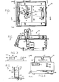
    • FIGURE 1 is a top plan view of an instrument in accordance with the invention, with the cover removed;
    • FIGURE 2 is a view in section taken along the line 2-2 of Figure 1, the bottom portion being broken off to conserve space;
    • FIGURE 3 is an enlarged fragmentary view in section taken along the line 3-3 of Figure 1, showing the photopotentiometer and phototransistor of the instrument;
    • FIGURE 4 is a front plan view, partially in section, of the instrument of Figurel;
    • FIGURE 5 is an enlarged fragmentary view in section, taken along line 5-5 of Figure 1 of the flow-through prism;
    • FIGURE 6 is a side view taken along the line 6-6 of Figure 4;
    • FIGURE 7 is a diagrammatic top plan view of the prismatic container showing varios light refraction paths;
    • FIGURE 8 is an enlarged view in longitudinal section of the light source, taken along the line 8-8 in Figure 1, the size of the light-emitting diode being exaggerated; and
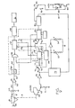
    • FIGURE 9 is an overall block diagram of the circuits included in the digital refractometer of Figure 1.
  • As shown in Figure 2, a digital refractometer 10 includes an enclosing opaque upper housing member 11 which may be made of a single piece of moulded plastics material. The opaque housing member 11 may be shaped to provide an integral funnel 12 through which a sample may be poured into a hollow prism 13. In an embodiment not adapted for flow-through capabilities, the hollow prism 13 may be removable and the funnel 12 may be replaced by a hinged or sliding opaque lid providing access to the removable prism when open and blocking light when closed during operation. However the illustrated embodiment is preferred, and here the prism 13 is secured in a fixed position. Transparent walls 14 and 15 of the prism 13 may be made of any suitable optical material including, for example, glass, plastics material, and quartz. The third wall 16 need not be transparent, though it can be.
  • In the embodiment adapted for flow-through capability, as may be seen in Figures 2 and 5, the hollow prism 13 is preferably triangular, having one non-optical side wall 16 and two transparent optical side walls 14 and 15 which meet each other at some suitable angle between about 40° and about 55°, to provide a good spread of light over a range of refractions. The prism 13 has an inlet opening 17 at its top, an overflow opening 18 in it side wall 16 disposed approximately two-thirds the height of the prism 13, a floor 19 sloped downwardly from the side wall 16 towards a point 20 along the edge where the two optical side walls 14 and 15 meet, and a drain opening 21 located at approximately the lowermost point of the sloped floor 19.
  • The overflow opening 18 is connected to an overflow tube 22, through which excess sample may be conducted (see Figure 6) to a waste receptacle outside the digital refractometer 10. The drain opening 21 is connected by a drain tube 23 to the inlet side of a solenoid drain valve 24, which remains closed during filling and testing and is then opened automatically to evacuate the hollow prism 13 after the test has been completed. The outlet side of the solenoid drain valve 24 may be connected to the same outside waste receptacle through the drain tube 23 or through a separate waste tube 25.
  • A light source 26 is provided at one side of the prism 13 to direct light toward and through the wall 14. This light source 26, as shown in Figure 8, preferably comprises a light-emitting diode 27 of a type that produces monochromatic light, housed in a metal member 28 through which is a bore 29 housing a lens 30 on the end opposite the light-emitting diode 27. The diode 27 preferably has a flat square emitting surface about 20 mils square, and thus is substantially a point source of light. The light source 26 must emit a beam of collimated monochromatic light. It may be a laser, an incandescent bulb, an LED, a zirconium arc lamp or the like. The lens 30 acts substantially to collimate the light of the diode 27 and direct it in a beam 31 toward the transparent prism wall 14. As shown in Figure 7, the wall 14 slightly refracts the beam 31 along prism wall path 32, and then the beam goes across the hollow interior of the prism 13 to the transparent wall 15. When the prism 13 is empty, the beam of light follows the interior path 33 from the wall 14 to the wall 15, is slightly refracted along the prism wall path 34 in the wall 15, and then emerges as a slightly divergent narrow beam 35 directed at a phototransistor 36. Figure 2 shows that the light source 26, the hollow prism 13, and the phototransistor 36 are disposed in a height relationship such that the beam 35 goes directly to and illuminatesthe phototransistor 36 when the prism 13 is empty.
  • A photopotentiometer 40 shown in Figures 1 and 2, and 3 is also disposed at substantially the same height as the phototransistor 36. When there is liquid 41 inside the hollow prism 13 and when the liquid fills the prism 13 all the way up to the overflow opening 18, then, as shown in Figure 7, the beam 31 follows interior refracted 42 path through the liquid 41 and a path 43 through the prism wall 15, and emerges as a refracted beam 44 directed at the photopotentiometer 40. Unlike the beam 35, which is always directed to the same point, the refracted beam 44 is affected by the solids content in the liquid 41. It may be directed toward the middle of the photopotentiometer 40. If the photopotentiometer 40 is placed across a +5 volts at one end terminal 45 and ground at its other end terminal 46, a beam 44 directed a its middle would give a voltage of 2.5 at the third or centre terminal 47. Movement of the beam 44 toward the terminal 45 increases the voltage at the centre terminal 47, while movement of the beam 44 toward the terminal 46 decreases the voltage at the centre terminal 47. The operation is substantially linear. In a preferred configuration the spot moves about 3.5 mm for specific gravities between 1.000 and 1.040; the voltage change at the centre terminal 47 is between about 1.7 volts and 3.3 volts.
  • Figure 1 shows the location of control means 50 and display means 51. The relative positions of the light source 26, the hollow prism 13, the photopotentiometer 40, and the phototransistor 36 on a compartment floor 52 are also shown. Line A represents the path of the light beam when the hollow prsim 13 is not sufficiently filled with sample, illuminating the phototransistor 36. Line B represents the path of light beam when the hollow prism 13 is sufficiently filled with sample 41, being refracted to illuminate a point along the photopotentiometer 40. The amount of refraction and consequently the point location along the photopotentiometer 40 which is illuminated is a function of the concentration of dissolved solutes in the sample being tested.
  • More specifically, as shown in Figure 7, the solids content of the liquid 41 affects the light refraction path B of Figure 1. Thus, clear water with a specific gravity of 1.000 causes the light to refract along a beam C in Figure 7. Urine with enough dissolved solids to give a specific gravity of 1.020 causes the light to refract along a beam D, while urine with more dissolved solid, enough to give a specific gravity of 1.040, causes the light to refract along a beams E. Each of the beam C, D and E strike the photopotentiometer 40 at a different location and accordingly changes the output voltage at the terminal 47. Specific gravities can then be determined to an accuracy of +0.001, and the values are almost instantly displayed.
  • The relative locations of the control means or calibration wheel 50, the display means 51, a green "ready" light 53, and a red "wait" light 54 are shown in Figure 4.
  • Figure 9 is a circuit diagram showing mostly in block form the way in which individually known elements are assembled. Alternatively, a microprocessor may perform all of the electronic functions except the sensing and amplifying functions. The LED 26 is shown as the light source, and its light after collimation passes through the prism 13, going either by path A to the phototransistor 36 or by path B to the photopotentiometer 40.
  • When the light from the LED 26 is directed by path B to the photopotentiometer 40 because there is solution in the prism 13, a refracted beam 44 is produced, as has already been described, which depends upon the amount of solids dissolved in the solution 41. A resultant signal then passes by line 60 to a differential amplifier 61 which is also fed by a reference line 62. The amplified difference signal is sent by a lead 63 to a voltage-to-frequency (i.e. analog to digital) converter 64 which, in turn, produces and transmits a digital signal along lead 65 to a gate 66, preferably a NAND gate. The gate controls the initiation and cessation of a decade counter 67, which is connected through a decoder driver 68 to a display 51.
  • When the prism 13 is empty, the beam from the LED 26 goes through the prism 13 along path A to the phototransistor 36. A voltage, for example +5 volts DC, is applied to the collector of the phototransistor 36 while the emitter is connected to the base of a second amplifying transistor 70, the collector of which is also connected to the +5 DC volts source. The emitter of the second transistor 70 is held above ground by a bias resistor 71 and is sent to a Schmitt trigger 72 which sends a signal to a latch circuit 73 and also to a first switch 74. The switch 74 has a normal operating position 75 and a calibration position 76. When the switch 74 is in its normal operation position 75, as shown in Figure 9, the signal is coupled by a resistance capacitance network 77 to the trigger input of a first timer 78.
  • The first timer 78 is connected by a lead 79 to the decade counter 67, and actuation of the first timer 78 resets the counter 67 to zero. Upon completion of its time interval, the first timer 78 sends a signal via a second switch 80 that actuates a second or testing duration timer 81. Actuation of the second timer 81 sends a signal via a line 81a to the NAND gate 66 that opens the gate and starts the decade counter 67 in its counting operation, which operation lasts only for the interval the second timer 81 is set for, and then turns off. When the NAND gate 66 is actuated, the digital signal is transmitted to the decade counter 67, and the decade counter 67 counts the digital pulses generated by the voltage-to-frequency converter 64 and passing through NAND gate 66 for the period of the second timer 81. When the second timer 81 completes its timed interval, the NAND gate 66 is closed, and then the decade counter 67 no longer receives a signal to count. The counted signal goes to the decoder driver 68 and from there to the display 69. It may be seen that the components 64, 66, 67, 68, 78 and 81 comprise an analog-to-digital converter.
  • When the second timer 81 reaches the end of its interval, it then actuates a third timer 82 to energize a solenoid 85 for the solenoid drain valve 24. There is a diode 86 in parallel with the solenoid 85. The third timer 82 also sends a signal along lead 87 to the latch 73.
  • The latch 73 controls whether the green light 53 or the red one 54 is lighted. At the end of its period, the third timer 82 causes the latch 73 to light the green light 53, showing that the device is ready to receive the next sample. When another sample has been put into the prism 13, the phototransistor circuit is actuated to send forth a signal from the Schmitt trigger 72 to the latch 73 so that the red light 54 is actuated. It remains actuated until the third timer 82, again, actuates the green light 53.
  • The calibration mode is selected by control switch handle 88 (as shown in Figure 4). Other elements in the calibrating circuit (as shown in Figure 9) include a first switch 74 connected to an astable timer 89, connected to a second switch 80, connected to a second timer 81, connected to a calibrating potentiometer 50, and a third switch 83.
  • When control switch handle 88 is put in the calibrate position, switches 74, 80 and 83 are moved to their respective calibrate positions 76. When phototransistor 36 ceases being illuminated and the resulting sharp cutoff in the circuit is caused by the Schmitt trigger 72, the astable timer 89 is actuated because the first switch 74 is in calibrate position 76. The astable time 89 turns on and off in one second pulses causing the decade counter 67 to reset to zero via connection through a lead 90. Since the second switch 80 is in calibrate position 76, the astable timer 89 also re-initiates the second timer 81, which, through its connected via the lead 82 to the NAND gate 66, causes repeated counting periods by the decade counter 67 and therefore repeated displays of the number corresponding to the concentration of dissolved solids in the sample on the display 51 through the decoder driver 68.
  • The third switch 83, also being in the calibrate position, conducts the output from the third timer 82, (which would normally actuate the solenoid 85 and cause draining) to ground, so that the sample does not drain during calibration.
  • The potentiometer 50 controls the length of time for which the second timer 81 is set. By testing a standard solution 41, having a known concentration of dissolved solids, in the calibrate mode, the period of the second timer 81 can be adjusted by the calibrating wheel 50 so that the decade counter 67 will count pulses from the analog-to-digital converter 64 for a time which will result in a reading on the display 51 which is the same as the known concentration of the standard.
  • Once the calibration is completed, the control switch handle 88 may be moved back to the test mode, the refractometer will go through a normal testing sequence commencing at the sharp cutoff by the Schmitt trigger 72' and will drain at the end since the third switch 83 is again passing the signal for the third timer 82 to actuate the solenoid 85 for draining.
  • The operation sequence will now be described with reference to Figures 1, 2 and 9. At the beginning, the green "ready" light 53 is lighted, the hollow prism 13 is empty, the solenoid drain valve 24 is closed, and the phototransistor 36 is illuminated by the beam from the light source 26. A sample 41 is poured through the funnel 12 into the inlet opening 17 of the hollow prism 13, filling the prism 13. Any excess sample, which could lie above the overflow opening 18 goes to waste via the overflow tube 22. Once the hollow prism 13 is filled sufficiently for testing, the light beam will be refracted away from the phototransistor 36, cutting off its output. This circuit is amplified and the Schmitt trigger 72 makes a sharp cutoff in the electronic circuit. This sharp cutoff actuates the first timer 78, and also actuates the latch 73 to turn off the green "ready" light 53, and to turn on the red "wait" light 54.
  • The first timer 78 measures a period of approximately 1 to 2 seconds, a sufficient time to allow any air bubbles in the sample to disperse. The first timer 78 then actuates the second timer 81 and resets the decade counter 67 to zero.
  • In the meantime, the beam from the light source 26 has been refracted and is illuminating a point along the photopotentiometer 40. The point on the photopotentiometer 40 on which the light beam falls corresponds to a particular output voltage, whichis received by the differential amplifier 61. The reference voltage 62, which may correspond to the photopotentiometer output voltage for either a clear solution or a solution having a fixed known concentration, (e.g.., in the middle of the range, such as sg. 1.020), is also received by differential amplifier 62, which measures the difference between its two input voltages and amplifies a signal corresponding to that difference. The amplified signal is received by the voltage-to-frequency converter 64, which converts amplitude to frequency. This frequency signal is one of the inputs to NAND gate 66.
  • The second timer 81 measures a period of approximately 40 milliseconds, and sends the second input to NAND gate 66 for that period of time. The NAND gate 66, having both input signals, opens and the frequency signal is received by the decade counter 67. The decade counter 67 counts each pulse it receives, receiving pulses so long as the NAND gate 66 is open, and passes on a signal which corresponds to that number of pulses to the decoder driver 68. The decoder driver 68 then causes a reading which corresponds to the specific gravity, concentration of dissolved solids, or refractive index of the test sample to be shown at display means 51.
  • At the end of its cycle, the second timer 81 triggers the third timer 82. The third timer 82 sends a signal through the switch 83 to the transistor 84, the signal of which actuates the solenoid 85 for the drain valve 24, causing it to open thereby draining the hollow prism 13 of any sample. The third timer 82 then also actuates the latch 73 to turn off the red "wait" light 54 and turn on the green "ready" light 53. At the end of the period of the third timer 82, its signal is turned off and solenoid controlled drain valve 24 closes.
  • Other electronic means such as a suitably programmed microprocessor may serve to perform many or all of the conversion and control functions of the electronic circuitry described herein. Recent advances in microprocessor technology include the integration of analog-to-digital converters and display driver circuitry along with the central processing unit, memory, etc. on a single chip. Such a device may cost effectively implement the design of the present invention, so that the complete apparatus may be very economically produced.
  • It will be appreciated that the above described refractometer is adapted for use by individual physicians and others having limited laboratory space. Also it will be appreciated that the device and method described above are equally applicable to measuring sugar concentration and other dissolved solids in liquids.
  • The above described device is no more expensive to manufacture than the American Optical Refractometer, although it provides quicker and more accurate determination of the specific gravity_of fluid.
  • The time required to test a given sample is dramatically reduced to the point where up to ten specimens may be tested in one minute.
  • The quantitive analysis of various body fuids and other liquids is performed by measuring the displacement of a beam of monochromatic light and the possibility of operaor error is greatly reduced, since measurement is automatic and the results are displayed digitally, eliminating the need for interpretation of a fine analog scale by the operator.
  • Also erroneous readings caused by the use of too small a sample are eliminated by a novel actuation system which delays the taking of readings until sufficient sample has been used. Further, erroneous readings are prevented by imposing a time delay in taking the reading for a time sufficient to ensure that any air bubble in the specimen will have dispersed. Only a small amount of specimen is required and no washing between samples is necessary for routine clinical testing. No high-power optical system is required, nor is any manual adjustment by the operator required in taking a reading.

Claims (10)

1. A method for determining the concentration of dissolved solids in a liquid sample, characterised in that said method comprises the steps of: placing a liquid sample to be tested into a hollow prismatic container (13) which is enclosed in an opaque housing (11), directing a collimated beam of monochromatic light (31) through the filled prismatic container, measuring (40) the refraction of the beam through the sample filled prism, and displaying (51) the measured refraction as a function of the concentration of dissolved solids in the sample.
2. A method according to claim 1 characterised in that the measuring step is deferred until after a predetermined amount of said sample has been placed in the prismatic container, and until after the predetermined amount has been in the container for a period sufficient to free the liquid in the container from air bubbles.
3. A method according to claim 1 or claim 2 characterised in that there is a step of automatically draining the sample from the prismatic container once the refraction of the beam has been measured, and indicating when the container has been drained and is ready to receive another sample.
4. A method of using a refractometer for determining the amount of dissolved solids in a series of sample solutions characterised in that said method comprises: directing a collimated monochromatic light beam (31) through an empty hollow prismatic container (13) and refracting it onto first light sensing means (36), indicating (53) when the refractometer is ready to receive a sample, introducing a sample solution into the prismatic container (13), thereby causing refraction of the collimated light beam passing therethrough to a second light-sensing means (40), instead of to the first light-sensing means (36), commencing the testing sequence only after all of the light beam has been refracted away from the first light-sensing means (36), and slmultaneously indicating (54) that testing is in progress, determining the amount of refraction of the light beam caused by passing through the sample solution, converting the amount of refraction of the light beam into an analog electrical signal, converting the analog signal to a digital signal, displaying digitally (51) an amount corresponding to the digital signal, stated as a function of the concentration of dissolved solids in the sample solution, automatically draining the prismatic container (13), and simultaneously causing the light beam to be refracted to the first light-sensing means (36), and automatically recommencing the sequence by indicating (53) that the refractometer is ready to receive another sample,
5. A refractometer for determining the concentration of dissolved solids in a sample solution, comprising an enclosing opaque housing, light source means in said housing for producing a beam of substantially collimated monochromatic light, and a container for a sample solution characterised in that said container is a hollow prismatic container (13) in said housing (11) having two transparent optical walls (14, 15) disposed in the path of said light beam (11), said refractometer further comprising light-sensing means (40) disposed in the refracted path (44) of said light beam after the said beam has passed through said prismatic container (13) when filled with a liquid sample and responsive to the exact refraction of said light heam, and display means (51) actuated by said light-sensing means foi displaying the refraction as a function of the concentration of dissolved solids in the liquid sample.
6. A refractometer according to claim 5 characterised in that diain means (24) are connected to said prismatic containet (13) and control means (82) open said drain means causing said prismatic container to be emptied after testing has been completed.
7. A refractometer for determining the concentration of dissolved solids in a sample solution, including in combination: an enclosing opaque housing, light source means in said housing for producing a beam of collimated monochromatic light, and a container for a sample solution characterised in that said container is a hollow prismatic container (13) in said housing (11) having two transparent optical vertical walls (14, 15) disposed in the path of said light beam (31) said refractometer further compris- esing first and second light-sensing means (36, 40) said first light-sensing means (36) being disposed in the path of said light beams after the said beam has passed through said prismatic container when empty, and said second light-sensing means (40) being disposed in the refracted path of said light beam after the said beam has passed through said prismatic container when filled with a liquid sample, said second light-sensing means including means responsive to the exact refraction of said light beam, control means (72) to actuate testing as soon as said first light-sensing means ceases being illuminated by said light beam, and differentiating means and display means (51) for comparing the exact refraction of said light beam through a sample to the exact refraction of said light beam through a reference sample and displaying that difference as a function of the concentration of dissolved solids in the test sample.
8. A refractometer according to claim 7 characterised in that said first light-sensing means is a phototransistor (36) which emits a signal upon being illuminated, and said control means to actuate testing is an electronic circuit comprising: an amplifier (70), connected to said phototransistor, a Schmitt trigger (72), connected to said amplifier (70), and a timer (78) connected to said Schmitt trigger via a switch (74) the signal of said phototransistor being amplified by said amplifier and received by said Schmitt trigger, so that when said phototransistor ceases being illuminated said Schmitt trigger is operated making a sharp cutoff in the electronic circuit which actuates said timer through said switch.
9. A'refractometer according to claim 8 charaterised in that said second light-sensing means (40) is a photo- potentiomeer emitting an output voltage which corresponds to the exact refraction of said light beam as caused by passing through a liquid sample, and said differentiating means is an electronic circuit comprising: a differential amplifier (61), said differential amplifier being connected to the output voltage of said photopotentiometer and amplifying an analog signal which corresponds to the difference between said output voltage and the output voltage of a liquid sample having a fixed predetermined concentration of dissolved solids, an analog-to-digital converter (64) connected to said differential amplifier, receiving said amplified analog signal, and converting it to a digital signal of pulses at a frequency which corresponds to said amplified analog signal, a testing duration timer (81), a gate (66) connected to and receiving the digital signal of pulses from said analog-to-digital converter, said gate also being connected to said testing duration timer to receive its output during its period, and a decade counter (67) is connected to the output of said gate,so that the digital signal of pulses passes through said gate to be counted by said decade counter only when the output of said timer is also received by the gate, the number of pulses counted by said decade counter being proportional to the concentration of dissolved solids in a test sample.
10. A refractometer according to claim 9 characterised in that calibrating means are provided for adjusting said differentiating means, said calibrating means comprising: first switch means (74), an astable timer (89) connected through said first switch means (88) to said control means (72) to actuate testing, said astable timer also being connected to said decade counter (67) to reset said decade counter at the beginning of each period of said astable timer, second switch means (80) connecting the output of said astable timer to actuate and re-actuate said testing duration timer at the beginning of each period of said astable timer, and adjustment means connected to said testing duration timer, said adjustment means controlling the period for which said testing duration timer is set.
EP80304784A 1980-02-28 1980-12-31 A refractometer Withdrawn EP0035081A3 (en)

Applications Claiming Priority (2)

Application Number Priority Date Filing Date Title
US125549 1980-02-28
US06/125,549 US4381895A (en) 1980-02-28 1980-02-28 Method and apparatus for automatic flow-through digital refractometer

Publications (2)

Publication Number Publication Date
EP0035081A2 true EP0035081A2 (en) 1981-09-09
EP0035081A3 EP0035081A3 (en) 1982-04-21

Family

ID=22420253

Family Applications (1)

Application Number Title Priority Date Filing Date
EP80304784A Withdrawn EP0035081A3 (en) 1980-02-28 1980-12-31 A refractometer

Country Status (3)

Country Link
US (1) US4381895A (en)
EP (1) EP0035081A3 (en)
JP (1) JPS56137139A (en)

Cited By (5)

* Cited by examiner, † Cited by third party
Publication number Priority date Publication date Assignee Title
EP0184911A2 (en) * 1984-12-06 1986-06-18 Warner-Lambert Technologies, Inc. Automatic refractometer
EP0524370A2 (en) * 1991-03-28 1993-01-27 Bayer Corporation Methods and devices for measuring the specific gravity of liquids
WO1994017393A1 (en) * 1993-01-27 1994-08-04 Anders Hanning An improved method of liquid bulk refractive index detection
WO2000013002A2 (en) * 1998-08-27 2000-03-09 Abbott Laboratories Reagentless analysis of biological samples
US7492447B2 (en) 2002-10-30 2009-02-17 Atago Co., Ltd. Refractometer

Families Citing this family (20)

* Cited by examiner, † Cited by third party
Publication number Priority date Publication date Assignee Title
US4514086A (en) * 1982-01-05 1985-04-30 Stine Edward V Apparatus for measuring refractive properties of lenses and other transmissive devices
US4689304A (en) * 1984-10-19 1987-08-25 Abbott Laboratories Air/liquid detection device for blood sample analysis
US4834104A (en) * 1985-08-01 1989-05-30 C. R. Bard, Inc. Method and apparatus for measuring specific gravity of a flowing liquid
US5015091A (en) * 1988-04-13 1991-05-14 Mitsubishi Denki K.K. Device for detecting alcoholic content
US4953956A (en) * 1988-06-10 1990-09-04 Carpenter David J Liquid prism device
US5110208A (en) * 1988-12-16 1992-05-05 The United States Of America As Represented By The United States Department Of Energy Measurement of average density and relative volumes in a dispersed two-phase fluid
GB9102963D0 (en) * 1991-02-12 1991-03-27 Index Instr Limited Liquid measuring apparatus and method
US5230223A (en) * 1992-03-20 1993-07-27 Envirosystems Corporation Method and apparatus for efficiently controlling refrigeration and air conditioning systems
US5696580A (en) * 1994-05-11 1997-12-09 Kyoto Dai-Ichi Kagaku Co., Ltd. Method of and apparatus for measuring absorbance, component concentration or specific gravity of liquid sample
US5870185A (en) * 1996-10-21 1999-02-09 C.F.C. Technology, Inc. Apparatus and method for fluid analysis
JP3063837B2 (en) * 1997-09-26 2000-07-12 日本電気株式会社 Urine multi-sensor
JP3537767B2 (en) 1998-11-13 2004-06-14 ライチャート インコーポレーティッド Method and apparatus for sensing the binding interaction between a binding layer and an analyte
JP4606543B2 (en) * 2000-04-13 2011-01-05 パナソニック株式会社 Method for confirming amount of solution to be measured and measuring system control method in optical property measuring apparatus
US6486944B1 (en) * 2001-06-08 2002-11-26 Leica Microsystems Inc. Fluid-sealed refractometer having data transmission means
US7280194B1 (en) 2004-11-30 2007-10-09 J.A. Woollam Co., Inc. Accurate determination of refractive indices of solid, fluid and liquid materials
JP4538364B2 (en) * 2005-04-18 2010-09-08 株式会社オハラ Refractive index measuring tool, refractive index measuring apparatus and refractive index measuring method
JP2009047436A (en) * 2007-08-13 2009-03-05 Atago:Kk Refractometer
US8692985B1 (en) 2012-11-19 2014-04-08 J.A. Woollam Co., Inc. Method of determining refractive index of prism shaped material
US10309897B2 (en) 2016-03-03 2019-06-04 J.A. Woollam Co., Inc. Method of determining refractive index, extinction coefficient, and surface properties of prism shaped material
CN106323810A (en) * 2016-11-14 2017-01-11 宜兴市晶科光学仪器有限公司 Specific gravity refraction tube for urine detection

Citations (3)

* Cited by examiner, † Cited by third party
Publication number Priority date Publication date Assignee Title
DE2036690A1 (en) * 1969-10-30 1971-05-13 Ste deOptique, Precision, Electro nique & Mecanique Sopelem, Paris Device for marking a transition in the lighting level
DE2324259B2 (en) * 1973-05-14 1976-04-15 Vdo Adolf Schindling Ag, 6000 Frankfurt DEVICE FOR MEASURING THE DENSITY OF A LIQUID USING THE LAW OF REFRIGERATION
GB2008793A (en) * 1977-11-04 1979-06-06 Anacon Instr Ltd Refractometers

Family Cites Families (5)

* Cited by examiner, † Cited by third party
Publication number Priority date Publication date Assignee Title
US2483102A (en) * 1945-05-02 1949-09-27 Robert M Pierson Refractometer employing photosensitive devices and use of the same
US3751168A (en) * 1971-05-11 1973-08-07 Sopelem Indicating apparatus for the varying concentration of a solution
US3713738A (en) * 1971-07-08 1973-01-30 Beet Sugar Dev Foundation Method and apparatus for rapidly and selectively determining purity of process streams
US4008405A (en) * 1975-06-05 1977-02-15 Analogic Corporation Motion detection circuit for electronic weighing system
US4193004A (en) * 1978-06-22 1980-03-11 Cobe Laboratories, Inc. Fluid level monitoring through fluid cell protrusion

Patent Citations (5)

* Cited by examiner, † Cited by third party
Publication number Priority date Publication date Assignee Title
DE2036690A1 (en) * 1969-10-30 1971-05-13 Ste deOptique, Precision, Electro nique & Mecanique Sopelem, Paris Device for marking a transition in the lighting level
US3672777A (en) * 1969-10-30 1972-06-27 Sopelem Apparatus for sensing a change in light intensity
DE2324259B2 (en) * 1973-05-14 1976-04-15 Vdo Adolf Schindling Ag, 6000 Frankfurt DEVICE FOR MEASURING THE DENSITY OF A LIQUID USING THE LAW OF REFRIGERATION
US4037967A (en) * 1973-05-14 1977-07-26 Vdo Adolf Schindling Ag Apparatus for measuring the density of a liquid, utilizing the law of refraction
GB2008793A (en) * 1977-11-04 1979-06-06 Anacon Instr Ltd Refractometers

Cited By (12)

* Cited by examiner, † Cited by third party
Publication number Priority date Publication date Assignee Title
EP0184911A2 (en) * 1984-12-06 1986-06-18 Warner-Lambert Technologies, Inc. Automatic refractometer
EP0184911A3 (en) * 1984-12-06 1987-07-29 Warner-Lambert Technologies, Inc. Automatic refractometer
EP0524370A2 (en) * 1991-03-28 1993-01-27 Bayer Corporation Methods and devices for measuring the specific gravity of liquids
EP0524370A3 (en) * 1991-03-28 1993-06-16 Miles Inc. Methods and devices for measuring the specific gravity of liquids
WO1994017393A1 (en) * 1993-01-27 1994-08-04 Anders Hanning An improved method of liquid bulk refractive index detection
WO2000013002A2 (en) * 1998-08-27 2000-03-09 Abbott Laboratories Reagentless analysis of biological samples
US6087182A (en) * 1998-08-27 2000-07-11 Abbott Laboratories Reagentless analysis of biological samples
WO2000013002A3 (en) * 1998-08-27 2001-02-22 Abbott Lab Reagentless analysis of biological samples
US6365109B1 (en) 1998-08-27 2002-04-02 Abbott Laboratories Reagentless analysis of biological samples
US6426045B1 (en) 1998-08-27 2002-07-30 Abbott Laboratories Reagentless analysis of biological samples
US6773922B2 (en) 1998-08-27 2004-08-10 Abbott Laboratories Reagentless analysis of biological samples
US7492447B2 (en) 2002-10-30 2009-02-17 Atago Co., Ltd. Refractometer

Also Published As

Publication number Publication date
JPS56137139A (en) 1981-10-26
US4381895A (en) 1983-05-03
EP0035081A3 (en) 1982-04-21

Similar Documents

Publication Publication Date Title
US4381895A (en) Method and apparatus for automatic flow-through digital refractometer
US5073500A (en) Method and apparatus for detecting urinary constituents
JP2651349B2 (en) Detector for fluid phase boundary in transparent measuring tube and accurate automatic metering device for liquid volume
US4231324A (en) Milk quantity meter
JPS6350650B2 (en)
NO160744B (en) PROCEDURE AND DEVICE FOR MEASURING BLOOD COAGULATION TIME.
US4474056A (en) Erythrocyte settling rate meter
CA1198970A (en) Apparatus to evaluate the "erythrayte sedimentation rate" (esr) in several samples
EP0087466A4 (en) Method and apparatus for detecting sample fluid.
US6172746B1 (en) Transmitted light refractometer
US4309112A (en) Rate measurement analyzer
JPH0619321B2 (en) Absorbance measuring device for microplate
US3448277A (en) Photoelectric absorption measurer having plunger for enclosing variable beam path lengths
EP0185285A2 (en) Liquid level measurement apparatus
JPS61254833A (en) Device for taking out fixed quantity of liquid
US6082204A (en) Titration method using a syringe
JPH04372861A (en) Detecting apparatus of liquid level
JPH0134335B2 (en)
US4834104A (en) Method and apparatus for measuring specific gravity of a flowing liquid
JP2548383B2 (en) Method and apparatus for detecting bubbles in liquid sample
WO1998002726A1 (en) Erythrosedimentation rate (esr) test apparatus
JPH0743379B2 (en) Immune reaction automatic analyzer
SU972331A1 (en) Touch-free stalagmometer
US3454337A (en) Apparatus for determining the number of white cells in a blood specimen
US5104511A (en) Electrophoresis system

Legal Events

Date Code Title Description
PUAI Public reference made under article 153(3) epc to a published international application that has entered the european phase

Free format text: ORIGINAL CODE: 0009012

AK Designated contracting states

Designated state(s): AT BE CH DE FR GB IT LU NL SE

PUAL Search report despatched

Free format text: ORIGINAL CODE: 0009013

AK Designated contracting states

Designated state(s): AT BE CH DE FR GB IT LU NL SE

STAA Information on the status of an ep patent application or granted ep patent

Free format text: STATUS: THE APPLICATION IS DEEMED TO BE WITHDRAWN

18D Application deemed to be withdrawn

Effective date: 19830324

RIN1 Information on inventor provided before grant (corrected)

Inventor name: FLAVELL, EVAN RICHARD

Inventor name: HUGHES, LEONARD ALLEN

Inventor name: WILLMAN, BENJAMIN C.