EP0034237B1 - Dental instrument with handpiece - Google Patents
Dental instrument with handpiece Download PDFInfo
- Publication number
- EP0034237B1 EP0034237B1 EP80810060A EP80810060A EP0034237B1 EP 0034237 B1 EP0034237 B1 EP 0034237B1 EP 80810060 A EP80810060 A EP 80810060A EP 80810060 A EP80810060 A EP 80810060A EP 0034237 B1 EP0034237 B1 EP 0034237B1
- Authority
- EP
- European Patent Office
- Prior art keywords
- parts
- intermediate section
- connector device
- handpiece
- connector
- Prior art date
- Legal status (The legal status is an assumption and is not a legal conclusion. Google has not performed a legal analysis and makes no representation as to the accuracy of the status listed.)
- Expired - Lifetime
Links
Images


Classifications
-
- A—HUMAN NECESSITIES
- A61—MEDICAL OR VETERINARY SCIENCE; HYGIENE
- A61C—DENTISTRY; APPARATUS OR METHODS FOR ORAL OR DENTAL HYGIENE
- A61C1/00—Dental machines for boring or cutting ; General features of dental machines or apparatus, e.g. hand-piece design
- A61C1/02—Dental machines for boring or cutting ; General features of dental machines or apparatus, e.g. hand-piece design characterised by the drive of the dental tools
- A61C1/05—Dental machines for boring or cutting ; General features of dental machines or apparatus, e.g. hand-piece design characterised by the drive of the dental tools with turbine drive
- A61C1/052—Ducts for supplying driving or cooling fluid, e.g. air, water
Definitions
- the invention relates to a dental instrument with a handpiece comprising a tool head and being removably mounted at the front end of an intermediate section of the instrument, which contains a micromotor intended to drive the tool. carried by the head of the handpiece, the rear end of this intermediate section being connected to a supply station by a flexible sheath and the handpiece being able to rotate freely relative to the sheath, around the axis of the instrument.
- the intermediate section containing the motor is, for its part, rigidly attached to a nozzle fixed to the end of the flexible sheath which connects the instrument to the supply station.
- its rear end has a bore which is engaged on a central barrel of the intermediate section, protruding at its front end and through which pass organs connecting the motor rotor to the tool carried by the handpiece. Since the engine rotates at relatively high speeds in modern dental instruments, it is important to cool the working place of the tool, while removing the debris it produces.
- the handpiece carries, either a nozzle intended to project a mixture of air and water in the direction of the working place, or else a pair of juxtaposed nozzles, intended to project in this direction, the 'one of water and the other of air producing a vaporization of water.
- These fluids come from the supply station. They are brought to the instrument by tubes contained in the flexible sheath and they pass through the intermediate section and the handpiece by channels arranged entirely or partially inside these elements.
- this flexible tube is generally part of the handpiece, to which it is permanently connected, and its free end is provided with a plug-in endpiece in the intermediate section.
- the handpiece includes only one nozzle.
- An air and water mixer is provided upstream of this tube, possibly in the tip of its free end, so that a single outer tube is sufficient for the production of the bleed and cooling jet (BR-CH 604 670).
- this solution has the disadvantage of limiting the rotation of the handpiece by the length of the outer tube.
- the longer this tube the greater the risk of tearing it off by hanging it on foreign objects. It can also interfere with the manipulation of the instrument, since it extends precisely in the zone of the latter which is held between the fingertips.
- connection between a channel of the intermediate section and the corresponding channel of the rotary handpiece is then established by an annular space provided between two contiguous surfaces of the intermediate section and the handpiece, and the sealing of which is ensured by two fittings arranged on either side of this space, in grooves of the intermediate section or of the handpiece.
- these grooves are formed, not in planar faces, but in cylindrical faces, so that the seals do not fall when changing the handpiece (BR-GB 1 519 513, BR-DE 2 334 448, BR-CH 604 670).
- connection of the intermediate section channels to those of the handpiece is direct. It can be done simply by introducing the protruding inputs of the channels of the handpiece into the outputs of the corresponding channels of the intermediate section, like what is done in each household with plugs and sockets.
- the rotary connector of the instrument according to the invention which is located at the rear end thereof, also has the advantage of forming a unit that the dentist does not need to dissociate.
- this swivel fitting is assembled once and for all, then manipulated in a block. A possible disassembly only takes place for repairs or overhauls, operations that specialized mechanics perform and not dentists.
- the instrument according to the invention Compared to known instruments, whose handpiece rotates relative to the intermediate section containing the micromotor, the instrument according to the invention also has the advantage of improving the conditions of use.
- the orientation of the tool can be changed by pronation or supination, that is to say by rotation of the whole hand and forearm, without having to change the position of the fingertips on the workpiece hand, as must be done with known instruments, to rotate the handpiece relative to the intermediate section.
- the sensitivity of the hand therefore remains strictly the same, whatever change in orientation of the tool that the dentist makes in the mouth of the patient.
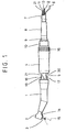
- the instrument represented in FIG. 1 comprises a handpiece 1 having, at its anterior end, a tool holder head 2, capable of receiving any of the conventional tools of dentists, in particular a milling cutter 3, and the drive in rotation about its axis.
- the handpiece 1 is intended to be attached to an intermediate section 4 of the instrument, which contains an electric micromotor of known type.
- This intermediate section 4 has a barrel 5, which projects from its front end and free passage to the motor shaft.
- this barrel 5 serves as a guide member.
- the barrel 5 penetrates into a bore of the handpiece and ensures the centering of the latter on the intermediate section 4 and also the correct coupling of the transmission members (not shown) provided between the micromotor contained in the section intermediate 4 and the cutter 3.
- the excitation of this motor is provided from a conventional supply station (not shown) by electrical wires 6, passing through a flexible sheath 7, connecting the supply station to the instrument.
- the sheath 7 is provided with a nozzle 8, which is fixed to a first part 9 of a connector, a second part 10 of which is fixed to the rear end of the intermediate section 4, the part 9 can rotate freely in part 10, coaxially with the instrument.
- the dentist can, thanks to the rotating connector 9, 10, modify at will the inclination of the axis of the cutter 3, without modifying the position of the fingertips on the handpiece 1, by simple supination or pronation of the hand and the forearm, and this, without being hampered by the resistance to twisting of the sheath 7.
- the supply station sends by a tube 11 contained in the sheath 7 a stream of cooling air to the engine, as well as water and air under pressure to the instrument by tubes 12 and 13 also contained in the sheath 7.
- These pressurized fluids pass longitudinally through the entire instrument, to arrive at juxtaposed nozzles 14 of the head 2, these nozzles being directed towards the end of the cutter 3.
- the air leaving one of these nozzles vaporizes the water leaving the other nozzle and produces a jet 15 of very fine water droplets towards the working place of the cutter 3.
- the flow rate of the water under pressure can be modified in a known manner and the consistency of the jet 15 adjusted as desired.
- the water supply can even be interrupted, so as to blow only air towards the work place, for example in order to purge debris produced following a work of the cutter 3.
- Water and air from the jet 15 are supplied to the nozzles 14 by channels which pass longitudinally through the handpiece 1 and which project at 17 and 18 at its rear end.
- these projecting ends 17 and 18 can be introduced into the channel outlet orifices (not shown) of the intermediate section 4, which communicate with the tubes 12 and 13 of the sheath 7.
- a conventional locking device (not shown) retains the handpiece 1 axially in place on the barrel 5.
- the supply station also sends light to the instrument by an optical fiber 21 passing through the sheath 7 and arriving at the head 2, from which it illuminates the working place.
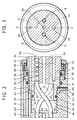
- FIG. 2 and 3 differ from that of FIG. 1 by the fact that it does not include lighting in the workplace, therefore no optical fiber.
- the part 9 of the rotary connector has three cylindrical surfaces 22, 23, 24, separated from each other by shoulders 25 and 26.
- a recess 27 is formed in the center of its front face.
- three channels 28, 29, 30 are drilled axially in this part 9.
- the first, 28, in the axis of part 9, opens at the center of the recess 27 and the second, 29, in the shoulder 25.
- the end piece 8 of the flexible sheath 7 (FIG. 1) is fixed to the part 9 so as to put the channel 28 in communication with the tube 11, the channel 29 with the tube 12 and the channel 30 with the tube 13.
- the part 10 of the rotary connector As for the part 10 of the rotary connector, it has three bores 32, 33, 34 and a thread 35. An internal ring 36 is driven into the bore 34. A clearance 37, turned in the ring 36, forms with the shoulder 38 of the part 10, located between its bores 33 and 34, an annular space 39 in the form of a groove all around the part 9 and into which the radial hole 31 of this part opens, whatever angular position it occupies with respect to Exhibit 10.
- the part 9 is retained in place in the part 10 with a slight axial clearance by its shoulder 26, which is trapped with the interposition of an axial ball bearing 40 between the ring 36 and a nut 41, screwed fully into the thread 35
- the bearing surface 23 of the part 9 enters the bore 33 of the part 10, however leaving a free space 42 between its shoulder 25 and the shoulder 43 of the part 10.
- the bearing surface 22 of the part 9 enters, from even, in the bore 32 of the part 10, however leaving a free space 44 between its front face 45 and the bottom 46 of the bore 32.
- Three channels 47, 48, 49 pass through the part 10, one, 47, central, from the bottom 46 of bore 32, the second, 48, from from the shoulder 43, and the last, 49, from the shoulder 38.
- the part 10 is fixed to the intermediate section 4 of the instrument using a nut 16 (Fig. 1), of so that channels 47, 48, 49 communicate with the corresponding channels in this section.
- the pressurized air arriving at the part 9 through the channel 30 can always pass through the channel 49 of the part 10 and finally arrive at the corresponding nozzle of the head 2 (Fig. 1) in whatever angular position the parts 9, 10 are in relation to each other.
- the annular space 42 allows the pressurized water to pass continuously from the channel 29 of the part 9 to the channel 48 of the part 10.
- the channels 28 and 47 for the engine cooling air they communicate with each other through the central chamber formed by the recess 27 and the free space 44.
- the tightness of the annular spaces 39 and 42 is guaranteed by three seals 50, 51, 52.
- the electrical wires 6 of the line supplying the micromotor are continuous. In line with the rotary union 9, 10, they pass through holes 53 and 54 of parts 9 and 10 and freely pass through the central chamber 27, 44 between these two parts. Given this arrangement of the wires 6, it is obvious that the parts 9, 10 cannot rotate indefinitely in the same direction.
- the part 10 carries a prisoner 55 which plunges into a groove 56 in the part 9, extending only over part of its periphery.
- Figs. 4 and 5 differs from the previous one only in the way in which the passage of the micromotor supply line contained in the intermediate section of the instrument is ensured through the rotary connector.
- a plug 57 made of insulating material is introduced into the recess 27 on the front face of the part 9 and a plate 58, also made of insulating material, is placed in the bottom of the bore 32 of the part 10.
- the plate 58 On its face turned towards the part 9, the plate 58 carries two conductive rings 59, 60, concentric, centered on the axis of rotation of the parts 9, 10.
- arms 61, 62 and connection parts 63, 64 passing through the plate 58, the rings 59, 60 are electrically connected to the micromotor by wires 65, 66.
- This optical fiber is composed of two strands 71, 72, the first, 71, coming from a light source of the power station, and, the second, 72, going towards the head 2 of the handpiece 1 ( Fig. 1).
- these two strands extend along the axis of rotation of the two parts which compose it, in order to remain end to end in all the relative angular positions of these two parts.
- a sleeve 73 is forcibly engaged in a bore 74 made in the center of the bottom of the bore 32 of the part 10.
- a ferrule 75 fixed to the end of the strand 71 , has a bearing 76 forcibly engaged in a bore 77 made in the center of the front face 45 of the part 9. It is, moreover, adjusted with gentle friction to the bore of the sleeve 73.
- the strand 72 of the optical fiber also carries an end piece 78 integral with the part 10 and the sleeve 73. Seals 79 prevent the infiltration of impurities in the space between the ends of the two strands of the optical fiber.
- the cooling air of the micromotor will naturally no longer be supplied by central channels of the two parts 9, 10, as in the embodiments of FIGS. 2 to 5, but by eccentric channels.
- the handpiece has two nozzles, respectively for air and for water. It can include only one, supplied with a cooling fluid established from air and water by a mixer which can be provided already in the supply station or between the latter and the instrument. described either in the intermediate section of the latter or in a part inserted between this section and the handpiece or, finally, in a nozzle at the end of a flexible tube of the handpiece, extending to the outside of the latter and intended to be plugged into a lateral orifice of the section intermediate. It is of course also possible to use any of the rotary couplings described above in a combined instrument for indifferently receiving handpieces in which the supply of the spray of water spray is ensured either by an internal channel or by an external flexible tube.
Landscapes
- Health & Medical Sciences (AREA)
- Oral & Maxillofacial Surgery (AREA)
- Dentistry (AREA)
- Epidemiology (AREA)
- Life Sciences & Earth Sciences (AREA)
- Animal Behavior & Ethology (AREA)
- General Health & Medical Sciences (AREA)
- Public Health (AREA)
- Veterinary Medicine (AREA)
- Dental Tools And Instruments Or Auxiliary Dental Instruments (AREA)
- Organic Low-Molecular-Weight Compounds And Preparation Thereof (AREA)
Abstract
Description
L'invention a trait à un instrument dentaire avec pièce à main comprenant une tête porte-outil et étant montée de manière amovible à l'extrémité antérieure d'une section intermédiaire de l'instrument, qui contient un micromoteur destiné à entraîner l'outil porté par la tête de la pièce à main, l'extrémité postérieure de cette section intermédiaire étant raccordée à une station d'alimentation par une gaine flexible et la pièce à main pouvant tourner librement par rapport à la gaine, autour de l'axe de l'instrument.The invention relates to a dental instrument with a handpiece comprising a tool head and being removably mounted at the front end of an intermediate section of the instrument, which contains a micromotor intended to drive the tool. carried by the head of the handpiece, the rear end of this intermediate section being connected to a supply station by a flexible sheath and the handpiece being able to rotate freely relative to the sheath, around the axis of the instrument.
Dans les instruments connus de ce type, c'est la pièce à main seule qui est rotative. La section intermédiaire contenant le moteur est, de son côté, attachée de façon rigide à un embout fixé à l'extrémité de la gaine flexible qui relie l'instrument à la station d'alimentation. Pour assurer la rotation de la pièce à main, son extrémité postérieure présente un alésage qui est engagé sur un canon central de la section intermédiaire, faisant saillie à son extrémité antérieure et à travers lequel passent des organes reliant le rotor du moteur à l'outil porté par la pièce à main. Comme le moteur tourne à des vitesses relativement élevées dans les instruments dentaires modernes, il importe de refroidir la place de travail de l'outil, tout en en évacuant les débris qu'il produit. A cet effet, la pièce à main porte, ou bien une buse destinée à projeter un mélange d'air et d'eau en direction de la place de travail, ou alors une paire de buses juxtaposées, destinées à projeter dans cette direction, l'une de l'eau et l'autre de l'air produisant une vaporisation de l'eau. Ces fluides proviennent de la station d'alimentation. Ils sont amenés à l'instrument par des tubes contenus dans la gaine flexible et ils traversent la section intermédiaire et la pièce à main par des canaux aménagés entièrement ou partiellement à l'intérieur de ces éléments.In known instruments of this type, it is the handpiece alone which is rotatable. The intermediate section containing the motor is, for its part, rigidly attached to a nozzle fixed to the end of the flexible sheath which connects the instrument to the supply station. To ensure the rotation of the handpiece, its rear end has a bore which is engaged on a central barrel of the intermediate section, protruding at its front end and through which pass organs connecting the motor rotor to the tool carried by the handpiece. Since the engine rotates at relatively high speeds in modern dental instruments, it is important to cool the working place of the tool, while removing the debris it produces. For this purpose, the handpiece carries, either a nozzle intended to project a mixture of air and water in the direction of the working place, or else a pair of juxtaposed nozzles, intended to project in this direction, the 'one of water and the other of air producing a vaporization of water. These fluids come from the supply station. They are brought to the instrument by tubes contained in the flexible sheath and they pass through the intermediate section and the handpiece by channels arranged entirely or partially inside these elements.
Pour connecter un canal de la section intermédiaire à un canal de la pièce à main rotative, la première solution qui vienne à l'esprit est de recourir à un tube souple s'étendant à l'extérieur de l'instrument, entre un orifice de sortie de la section intermédiaire et un orifice d'entrée de la pièce à main. C'est aussi la première qui a été introduite dans la pratique. Dans ce cas, ce tube souple fait généralement partie de la pièce à main, à laquelle il est relié en permanence, et son extrémité libre est munie d'un embout enfichable dans la section intermédiaire.To connect a channel of the intermediate section to a channel of the rotary handpiece, the first solution that comes to mind is to use a flexible tube extending outside the instrument, between a orifice outlet of the intermediate section and an inlet opening of the handpiece. It is also the first that has been introduced into practice. In this case, this flexible tube is generally part of the handpiece, to which it is permanently connected, and its free end is provided with a plug-in endpiece in the intermediate section.
Vu l'encombrement causé par un tel tube souple, la pièce à main ne comprend qu'une seule buse. Un mélangeur de l'air et de l'eau est prévu en amont de ce tube, éventuellement dans l'embout de son extrémité libre, de sorte qu'un seul tube extérieur suffit à la production du jet purgeur et de refroidissement (BR-CH 604 670).Given the space caused by such a flexible tube, the handpiece includes only one nozzle. An air and water mixer is provided upstream of this tube, possibly in the tip of its free end, so that a single outer tube is sufficient for the production of the bleed and cooling jet (BR-CH 604 670).
Cette solution a toutefois l'inconvénient de limiter la rotation de la pièce à main par la longueur du tube extérieur. Par ailleurs, plus ce tube est long, plus grand est le risque de l'arracher en l'accrochant à des objets étrangers. Il peut aussi gêner la manipulation de l'instrument, car il s'étend précisément dans la zone de celui-ci qui est tenue entre le bout des doigts.However, this solution has the disadvantage of limiting the rotation of the handpiece by the length of the outer tube. In addition, the longer this tube, the greater the risk of tearing it off by hanging it on foreign objects. It can also interfere with the manipulation of the instrument, since it extends precisely in the zone of the latter which is held between the fingertips.
C'est pourquoi actuellement, la préférence est donnée aux solutions dans lesquelles les canaux traversant l'instrument sont situés entièrement à l'intérieur de ses éléments. La connexion entre un canal de la section intermédiaire et le canal correspondant de la pièce à main rotative est alors établie par un espace annulaire prévu entre deux surfaces contiguës de la section intermédiaire et de la pièce à main, et dont l'étanchéité est assurée par deux garnitures disposées de part et d'autre de cet espace, dans des rainures de la section intermédiaire ou de la pièce à main. Dans les exécutions pratiques, ces rainures sont formées, non dans des faces planes, mais dans des faces cylindriques, afin que les garnitures d'étanchéité ne tombent pas lors d'un changement de la pièce à main (BR-GB 1 519 513, BR-DE 2 334 448, BR-CH 604 670).This is why currently, preference is given to solutions in which the channels passing through the instrument are located entirely inside its elements. The connection between a channel of the intermediate section and the corresponding channel of the rotary handpiece is then established by an annular space provided between two contiguous surfaces of the intermediate section and the handpiece, and the sealing of which is ensured by two fittings arranged on either side of this space, in grooves of the intermediate section or of the handpiece. In practical embodiments, these grooves are formed, not in planar faces, but in cylindrical faces, so that the seals do not fall when changing the handpiece (BR-GB 1 519 513, BR-DE 2 334 448, BR-CH 604 670).
Lors de l'accrochement d'une pièce à main à la section intermédiaire de l'instrument, ce qui se fait assez fréquemment, ces garnitures d'étanchéité sont donc ou bien comprimées pour s'introduire dans un alésage, ou alors distendues, pour s'engager sur une face cylindrique, selon qu'elles se trouvent dans des rainures d'une portée cylindrique ou d'un alésage. Dans les deux cas, c'est l'arête frontale de l'alésage ou de la portée cylindrique qui produit cette déformation des garnitures d'étanchéité. Or, il n'est pas rare que ces garnitures soient endommagées par cette arête, par exemple à la suite d'un accrochage trop brusque et pas très adroit de la pièce à main à la section intermédiaire.When attaching a handpiece to the intermediate section of the instrument, which is done quite frequently, these seals are therefore either compressed to be introduced into a bore, or then stretched, to engage on a cylindrical face, depending on whether they are in grooves of a cylindrical bearing or of a bore. In both cases, it is the front edge of the bore or of the cylindrical seat which produces this deformation of the seals. However, it is not uncommon for these seals to be damaged by this edge, for example as a result of too sudden and not very skilful attachment of the handpiece to the intermediate section.
La solution définie par la caractéristique de la revendication 1 élimine ce risque. La connexion des canaux de la section intermédiaire à ceux de la pièce à main est directe. Elle peut se faire simplement en introduisant les entrées en saillie des canaux de la pièce à main dans les sorties des canaux correspondants de la section intermédiaire, à l'instar de ce qui se fait dans chaque ménage avec les fiches et prises de courant électrique.The solution defined by the characteristic of claim 1 eliminates this risk. The connection of the intermediate section channels to those of the handpiece is direct. It can be done simply by introducing the protruding inputs of the channels of the handpiece into the outputs of the corresponding channels of the intermediate section, like what is done in each household with plugs and sockets.
Le raccord tournant de l'instrument selon l'invention, qui se trouve à l'extrémité postérieure de celui-ci, a aussi l'avantage de former une unité que le dentiste n'a pas besoin de dissocier. Pratiquement, ce raccord tournant est assemblé une fois pour toutes, puis manipulé en bloc. Un démontage éventuel n'intervient, en effet, que pour des réparations ou des révisions, opérations que des mécaniciens spécialisés effectuent et non les dentistes.The rotary connector of the instrument according to the invention, which is located at the rear end thereof, also has the advantage of forming a unit that the dentist does not need to dissociate. In practice, this swivel fitting is assembled once and for all, then manipulated in a block. A possible disassembly only takes place for repairs or overhauls, operations that specialized mechanics perform and not dentists.
Par rapport aux instruments connus, dont la pièce à main tourne par rapport à la section intermédiaire contenant le micromoteur, l'instrument selon l'invention a encore l'avantage d'améliorer les conditions d'utilisation. L'orientation de l'outil peut être modifiée par pronation ou par supination, c'est-à-dire par rotation de toute la main et de l'avant-bras, sans avoir à modifier la position du bout des doigts sur la pièce à main, comme il faut le faire avec les instruments connus, pour faire tourner la pièce a main par rapport à la section intermédiaire. Avec l'instrument selon l'invention, la sensibilité de la main reste donc rigoureusement la même quelque changement d'orientation de l'outil que le dentiste effectue dans la bouche du patient.Compared to known instruments, whose handpiece rotates relative to the intermediate section containing the micromotor, the instrument according to the invention also has the advantage of improving the conditions of use. The orientation of the tool can be changed by pronation or supination, that is to say by rotation of the whole hand and forearm, without having to change the position of the fingertips on the workpiece hand, as must be done with known instruments, to rotate the handpiece relative to the intermediate section. With the instrument according to the invention, the sensitivity of the hand therefore remains strictly the same, whatever change in orientation of the tool that the dentist makes in the mouth of the patient.
L'idée de faciliter la manipulation d'un instrument dentaire de cette façon n'est pas nouvelle pour des pièces à main dentaires dont la tête porte-outil est équipée d'une turbine à air, au rotor de laquelle l'outil de travail est fixé pour être entrainé à de très grandes vitesses : plusieurs centaines de mille tours par minute (US-A-3 521 359, FR-A-2 173 034, FR-A-2 199 964, US-A-3 921 296, US-A-4 177 564, FR-A-2 403 065).The idea of facilitating the manipulation of a dental instrument in this way is not new for dental handpieces whose tool holder head is equipped with an air turbine, to the rotor of which the working tool is set to be driven at very high speeds: several hundred thousand revolutions per minute (US-A-3,521,359, FR-A-2,173,034, FR-A-2,199,964, US-A-3,921,296 , US-A-4,177,564, FR-A-2,403,065).
Par contre, ceci n'a pas pu être réalisé jusqu'à ce jour pour des pièces à main équipées de micromoteur électriques pour lesquelles, outre l'air et l'eau, il est encore nécessaire de prévoir des conducteurs électriques pour l'alimentation du moteur qui doivent également traverser le raccord tournant pour obtenir le but visé. C'est précisemment ce que propose la présente invention.On the other hand, this has not been possible to date for handpieces equipped with electric micromotors for which, in addition to air and water, it is also necessary to provide electrical conductors for the supply. of the motor which must also pass through the swivel joint to obtain the intended goal. This is precisely what the present invention offers.
Quelques formes d'exécution de l'instrument selon l'invention sont décrites ci-après, à titre d'exemple, en référence au dessin, dans lequel;
- La figure 1 est une vue générale en élévation d'une forme d'exécution de l'instrument selon l'invention, la pièce à main étant partiellement séparée de la section intermédiaire;
- La figure 2 est une coupe à granche échelle, selon la ligne II-II de la figure 3, montrant un détail d'une autre forme d'exécution;
- La figure 3 est une vue en bout de l'extrémité droite de la Figure 2;
- La figure 4 est une vue partiellement en coupe selon la ligne IV-IV de la Figure 5 du même détail que celui de la Figure 2, mais d'une autre forme d'exécution;
- La figure 5 est une vue en bout de l'extrémité droite de la Figure 4,
- La figure 6 est une vue semblable à celle de la Figure 4 d'un détail d'une dernière forme d'exécution.
- Figure 1 is a general elevational view of an embodiment of the instrument according to the invention, the handpiece being partially separated from the intermediate section;
- Figure 2 is a sectional section, along the line II-II of Figure 3, showing a detail of another embodiment;
- Figure 3 is an end view of the right end of Figure 2;
- Figure 4 is a partially sectional view along line IV-IV of Figure 5 of the same detail as that of Figure 2, but of another embodiment;
- FIG. 5 is an end view of the right end of FIG. 4,
- Figure 6 is a view similar to that of Figure 4 of a detail of a last embodiment.
L'instrument représenté à la figure 1 comprend une pièce à main 1 ayant, à son extrémité antérieure, une tête 2 porte-outil, capable de recevoir n'importe lequel des outils conventionnels des dentistes, en particulier une fraise 3, et de l'entraîner en rotation autour de son axe. La pièce à main 1 est destinée à être rattachée à une section intermédiaire 4 de l'instrument, qui contient un micromoteur électrique de type connu. Cette section intermédiaire 4 présente un canon 5, qui fait saillie de son extrémité antérieure et livre passage à l'arbre du moteur. Lors de la mise en place d'une pièce à main 1 sur la section intermédiaire 4, ce canon 5 lui sert d'organe de guidage. A cet effet, le canon 5 pénètre dans un alésage de la pièce à main et assure le centrage de cette dernière sur la section intermédiaire 4 et aussi l'accouplement correct des organes de transmission (non représentés) prévus entre le micromoteur contenu dans la section intermédiaire 4 et la fraise 3.The instrument represented in FIG. 1 comprises a handpiece 1 having, at its anterior end, a
L'excitation de ce moteur est assurée à partir d'une station d'alimentation conventionelle (non représentée) par des fils électriques 6, passant à travers une gaine flexible 7, reliant la station d'alimentation à l'instrument. A son extrémité aval, la gaine 7 est munie d'un embout 8, qui est fixé à une première pièce 9 d'un raccord, dont une seconde pièce 10 est fixée à l'extrémité postérieure de la section intermédiaire 4, la pièce 9 pouvant tourner librement dans la pièce 10, coaxialement à l'instrument.The excitation of this motor is provided from a conventional supply station (not shown) by
Au cours d'un travail dans la bouche d'un patient, le dentiste peut, grâce au raccord tournant 9, 10, modifier à volonté l'inclinaison de l'axe de la fraise 3, sans modifier la position du bout des doigts sur la pièce à main 1, par simple supination ou pronation de la main et de l'avant-bras, et cela, sans être gêné par la résistance à la torsion de la gaine 7.During a work in the mouth of a patient, the dentist can, thanks to the
Comme le micromoteur et la fraise 3 tournent à des vitesses de l'ordre de quelques dizaines de milliers de tours par minute, il est indispensable d'assurer le refroidissement non seulement du moteur, mais aussi de la place de travail. A cet effet, la station d'alimentation envoie par un tube 11 contenu dans la gaine 7 un courant d'air de refroidissement au moteur, ainsi que de l'eau et de l'air sous pression à l'instrument par des tubes 12 et 13 également contenus dans la gaine 7. Ces fluides sous pression traversent longitudinalement tout l'instrument, pour arriver à des buses juxtaposées 14 de la tête 2, ces buses étant dirigées vers l'extrémité de la fraise 3. L'air sortant de l'une de ces buses vaporise l'eau sortant de l'autre buse et produit un jet 15 de très fines gouttelettes d'eau en direction de la place de travail de la fraise 3. A l'aide d'une bague rotative (non représentée), qui pourrait être agencée en amont du raccord tournant, le débit de l'eau sous pression peut être modifié de façon connue et la consistance du jet 15 réglée à volonté. L'amenée d'eau peut même être interrompue, de façon à ne plus souffler que de l'air en direction de la place de travail, par exemple en vue de la purger des débris produits à la suite d'un travail de la fraise 3.As the micromotor and the
L'eau et l'air du jet 15 sont amenés aux buses 14 par des canaux qui traversent longitudinalement la pièce à main 1 et qui font saillie en 17 et 18 à son extrémité postérieure. En orientant convenablement la pièce à main 1 autour du canon 5, ces extrémités saillantes 17 et 18 peuvent être introduites dans des orifices de sortie de canaux (non représentés) de la section intermédiaire 4, qui communiquent avec les tubes 12 et 13 de la gaine 7. Lorsque la face postérieure 19 de la pièce à main 1 est plaquée contre la face antérieure 20 de la section intermédiaire 4, un dispositif de verrouillage conventionnel (non représenté) retient la pièce à main 1 axialement en place sur le canon 5.Water and air from the
Dans la forme d'exécution de la Fig. 1, la station d'alimentation envoie encore de la lumière à l'instrument par une fibre optique 21 passant à travers la gaine 7 et arrivant jusqu'à la tête 2, d'où elle éclaire la place de travail.In the embodiment of FIG. 1, the supply station also sends light to the instrument by an
Dans un instrument qui serait solidaire en rotation de la gaine 7, l'équipement décrit ci-dessus ne présenterait aucune difficulté d'agencement. On comprendra cependant qu'il n'est possible dans la forme d'exécution décrite qu'à la condition d'arriver à faire passer l'ensemble des lignes d'alimentation contenues dans la gaine 7 à travers les deux pièces du raccord 9, 10, qui doivent pouvoir tourner librement l'une dans l'autre.In an instrument which is integral in rotation with the
Quelques formes d'exécution de ce raccord sont représentées en détail dans les figures suivantes du dessin.Some embodiments of this connection are shown in detail in the following figures of the drawing.
La forme d'exécution représentée aux Fig. 2 et 3 diffère toutefois de celle de la Fig. 1 par le fait qu'elle ne comprend pas d'éclairage de la place de travail, donc pas de fibre optique.The embodiment shown in Figs. 2 and 3, however, differ from that of FIG. 1 by the fact that it does not include lighting in the workplace, therefore no optical fiber.
La pièce 9 du raccord tournant présente trois portées cylindriques 22, 23, 24, séparées les unes des autres par des épaulements 25 et 26. Une creusure 27 est formée au centre de sa face antérieure. Enfin, trois canaux 28, 29, 30 sont percés axialement dans cette pièce 9. Le premier, 28, dans l'axe de la pièce 9, débouche au centre de la creusure 27 et le second, 29, dans l'épaulement 25. Quant au troisième perçage, 30, il est borgne, mais un canal 31, percé radialement, le relie à la portée 23. L'embout 8 de la gaine flexible 7 (Fig. 1) est fixé à la pièce 9 de façon à mettre en communication le canal 28 avec le tube 11, le canal 29 avec le tube 12 et le canal 30 avec le tube 13.The
Quant à la pièce 10 du raccord tournant, elle présente trois alésages 32, 33, 34 et un filetage 35. Une bague interne 36 est chassée dans l'alésage 34. Un dégagement 37, tourné dans la bague 36, forme avec l'épaulement 38 de la pièce 10, situé entre ses alésages 33 et 34, un espace annulaire 39 en forme de gorge tout autour de la pièce 9 et dans lequel débouche le trou radial 31 de cette pièce, quelque position angulaire qu'elle occupe par rapport à la pièce 10.As for the
La pièce 9 est retenue en place dans la pièce 10 avec un léger jeu axial par son épaulement 26, qui est emprisonné avec interposition d'un roulement à billes axial 40 entre la bague 36 et un écrou 41, vissé à fond dans le filetage 35. La portée 23 de la pièce 9 pénètre dans l'alésage 33 de la pièce 10, en laissant toutefois un espace libre 42 entre son épaulement 25 et l'épaulement 43 de la pièce 10. La portée 22 de la pièce 9 entre, de même, dans l'alésage 32 de la pièce 10, en laissant cependant un espace libre 44 entre sa face frontale 45 et le fond 46 de l'alésage 32. Trois canaux 47, 48, 49 traversent la pièce 10, l'un, 47, central, à partir du fond 46 de l'alésage 32, le second, 48, à partir de l'épaulement 43, et le dernier, 49, à partir de l'épaulement 38. La pièce 10 est fixée à la section intermédiaire 4 de l'instrument à l'aide d'un écrou 16 (Fig. 1), de façon que les canaux 47, 48, 49 communiquent avec les canaux correspondants de cette section.The
Grâce à l'espace annulaire 39, l'air sous pression arrivant à la pièce 9 par le canal 30 peut toujours passer dans le canal 49 de la pièce 10 et arriver finalement à la buse correspondante de la tête 2 (Fig. 1) dans quelque position angulaire que se trouvent les pièces 9, 10 l'une par rapport à l'autre. De même, l'espace annulaire 42 permet à l'eau sous pression de passer en permanence du canal 29 de la pièce 9 au canal 48 de la pièce 10. Quant aux canaux 28 et 47 pour l'air de refroidissement du moteur, ils communiquent entre eux par la chambre centrale constituée par la creusure 27 et l'espace libre 44. L'étanchéité des espaces annulaires 39 et 42 est garantie par trois garnitures d'étanchéité 50, 51, 52.Thanks to the
Dans cette forme d'exécution, les fils électriques 6 de la ligne alimentant le micromoteur sont continus. Au droit du raccord tournant 9, 10, ils passent dans des forures 53 et 54 des pièces 9 et 10 et traversent librement la chambre centrale 27, 44 entre ces deux pièces. Vu cette disposition des fils 6, il est évident que les pièces 9, 10 ne sauraient tourner indéfiniment dans le même sens. Dans cette forme d'exécution, la pièce 10 porte un prisonnier 55 qui plonge dans une rainure 56 de la pièce 9, s'étendant seulement sur une partie de sa périphérie.In this embodiment, the
La forme d'exécution des Fig. 4 et 5 ne diffère de la précédente que par la façon dont le passage de la ligne d'alimentation du micromoteur contenu dans la section intermédiaire de l'instrument est assuré à travers le raccord tournant. Dans cette exécution, un bouchon 57 en matière isolante est introduit dans la creusure 27 de la face frontale de la pièce 9 et une plaque 58, également en matière isolante, est disposée dans le fond de l'alésage 32 de la pièce 10. Sur sa face tournée vers la pièce 9, la plaque 58 porte deux anneaux conducteurs 59, 60, concentriques, centrés sur l'axe de rotation des pièces 9, 10. Par des bras 61, 62 et des pièces de connexion 63, 64 traversant la plaque 58, les anneaux 59, 60 sont reliés électriquement au micromoteur par des fils 65, 66. Quant aux fils 6, contenus dans la gaine 7 (Fig. 1), ils aboutissent dans des forures de la pièce 9 et du bouchon 57, dont les distances à l'axe de rotation des pièces 9, 10 sont égales aux rayons moyens des anneaux 59, 60. Des balais 67, 68, guidés dans les forures du bouchon 57, sont poussés contre les anneaux 59, 60 par des ressorts 69 prenant appui sur des capuchons 70 soudés aux extrémités des fils 6 et établissent ainsi un contact à frottement qui, dans toutes les positions relatives des pièces 9 et 10, relie en permanence les fils 6 arrivant de la station d'alimentation aux fils 65 et 66 connectés au moteur. Par rapport à la forme d'exécution des Fig. 2 et 3, celle des Fig. 4 et 5 a ainsi l'avantage de permettre des rotations relatives illimitées des pièces 9 et 10.The embodiment of Figs. 4 and 5 differs from the previous one only in the way in which the passage of the micromotor supply line contained in the intermediate section of the instrument is ensured through the rotary connector. In this embodiment, a
La dernière forme d'exécution (Fig. 6) se distingue des précédentes par l'agencement d'un éclairage par fibre optique de la place de travail.The last form of execution (Fig. 6) stands out of the previous ones by the arrangement of a fiber optic lighting of the workplace.
Cette fibre optique est composée de deux brins 71, 72, le premier, 71, arrivant d'une source de lumière de la station d'alimentation, et, le second, 72, allant vers la tête 2 de la pièce à main 1 (Fig. 1). Dans le raccord 9, 10, ces deux brins s'étendent selon l'axe de rotation des deux pièces qui le composent, afin de rester bout à bout dans toutes les positions angulaires relatives de ces deux pièces. Pour garantir la coaxialité des deux brins de la fibre optique, un manchon 73 est engagé à force dans une forure 74 pratiquée au centre du fond de l'alésage 32 de la pièce 10. Un embout 75, fixé à l'extrémité du brin 71, présente une portée 76 engagée à force dans une forure 77 pratiquée au centre de la face frontale 45 de la pièce 9. Il est, par ailleurs, ajusté à frottement doux à l'alésage du manchon 73 . Le brin 72 de la fibre optique porte, de même, un embout 78 solidaire de la pièce 10 et du manchon 73. Des garnitures d'étanchéité 79 préviennent l'infiltration d'impuretés dans l'espace entre les extrémités des deux brins de la fibre optique.This optical fiber is composed of two
Dans cette forme d'exécution, l'air de refroidissement du micromoteur ne sera naturellement plus amené par des canaux centraux des deux pièces 9, 10, comme dans les exécutions des Fig. 2 à 5, mais par des canaux excentrés.In this embodiment, the cooling air of the micromotor will naturally no longer be supplied by central channels of the two
Vu que les coordonnées et les dimensions des différents canaux des instruments dentaires sont normalisées, il suffit d'adapter les entrées et sorties des canaux des raccords décrits à ces coordonnées et dimensions pour permettre l'utilisation de ces raccords avec n'importe quel instrument existant.Since the coordinates and dimensions of the different channels of dental instruments are standardized, it suffices to adapt the inputs and outputs of the channels of the fittings described to these coordinates and dimensions to allow the use of these fittings with any existing instrument. .
Par ailleurs, il n'est pas indispensable que la pièce à main ait deux buses, respectivement pour l'air et pour l'eau. Elle peut n'en comprendre qu'une seule, alimentée par un fluide de refroidissement établi à partir d'air et d'eau par un mélangeur qui peut être prévu déjà dans la station d'alimentation ou entre celle-ci et l'instrument décrit ou bien dans la section intermédiaire de ce dernier ou encore dans une pièce insérée entre cette section et la pièce à main ou, enfin, dans un embout à l'extrémité d'un tube souple de la pièce à main, s'étendant à l'extérieur de cette dernière et destiné à être enfiché dans un orifice latéral de la section intermédiaire. Il est naturellement aussi possible d'utiliser l'un quelconque des raccords tournants décrits ci-dessus dans un instrument combiné pour recevoir indifféremment des pièces à main dans lesquelles l'alimentation du jet d'eau vaporisée est assurée soit par un canal intérieur soit par un tube souple extérieur.Furthermore, it is not essential that the handpiece has two nozzles, respectively for air and for water. It can include only one, supplied with a cooling fluid established from air and water by a mixer which can be provided already in the supply station or between the latter and the instrument. described either in the intermediate section of the latter or in a part inserted between this section and the handpiece or, finally, in a nozzle at the end of a flexible tube of the handpiece, extending to the outside of the latter and intended to be plugged into a lateral orifice of the section intermediate. It is of course also possible to use any of the rotary couplings described above in a combined instrument for indifferently receiving handpieces in which the supply of the spray of water spray is ensured either by an internal channel or by an external flexible tube.
Claims (4)
- A dental instrument of the type driven by an electric micromotor, including a tool carrying head (2) fastened to a handpiece (1) removably mounted on an intermediate section (4) by a first connector (5) locking together in rotation the handpiece (1) and the intermediate section (4), a micromotor housed in said intermediate section (4), a rotatory connector device (10, 9) connected on the one hand through a second connector (16) to the intermediate section (4) and connected on the other hand through an adaptor (8) to a flexible sheath (7) which in turn is connected to a supply source, said first connector including guide means (5) for ensuring the centering of the handpiece (1) with respect to the intermediate section (4) and the mechanical coupling of the transmission members provided between the micromotor and the tool carrying head (2), the second connector including a nut (16) designed for fastening the intermediate section (4) to said rotatory connector device, the latter including two parts (9, 10) which can rotate freely with respect to each other and which include parts (22, 23; 32, 33) lodged one inside the other and forming together a sliding bearing which allows one of these parts to rotate freely with respect to the other, the supply of a device (14), which projects a fluid (15) in the direction of the tool (3), being provided for by conduits for respectively water and air, which the supply source projects under pressure through tubes (12, 13) housed in said flexible sheath (7), each one of these conduits including a channel (29, 30) extending through one (9) of the said parts of the rotatory connector device (9, 10), which is connected to one of said tubes (12, 13) and which communicates with a second channel (48, 49) extending through the other piece (10) of this rotatory connector device (9, 10) through a sealed annular space (39, 42) formed between the corresponding shoulders (26, 38; 25, 43) of the two parts (9, 10) located in the sections thereof which are fitted into each other, electric conductors (6, 65, 66) being lodged in each one of said two parts (9, 10) of the connector device, a central chamber (27, 44) being provided between the end of one of said parts (9) of the connector which is engaged in a central housing of the other part (10), and the bottom (46) of this housing including a movable connexion (6; 59, 60; 67, 68) for each one of the electric conductors of one (9) of the parts connecting the same to the corresponding conductor of the other part (10), so as to ensure the passage through the connector device of electric current supplying the electric micromotor contained in the intermediate section (4).
- A dental instrument according to claim 1, characterized in that the supply of said motor is provided for by insulated electric wires (6) housed inside bores (53, 54) of the two said parts (9, 10) and extending freely through said central chamber (27, 44), a stop mechanism (55, 56) limiting the extent of rotation of one of the parts of said connector device rotating relatively to the other and channels (28, 47) provided in the two parts of the connector device, which communicate with each other through said central chamber (27, 44) and which ensure the arrival to the motor of a flow of cooling air supplied from the supply source via a tube (11) housed inside said flexible sheath (7).
- A dental instrument according to claim 1, characterized in that the supply of said micromotor is provided for by conductors (6, 65, 66) engaged inside bores in said two parts of said connector device, the conductors of one of said parts being connected to those of the other part by a friction contact device (67, 68; 59, 60) housed in said central chamber (27, 44) and including brushes (67, 68) which are mounted at the ends of the conductors (6) of one of said parts of the connector device and which abut against annular rings (59, 60) to which are connected the conductors (65, 66) of the other part (10) of the connector device (9, 10) and by channels (28, 47) bored through the two parts of the connector device which communicate between themselves through said central chamber (27, 44) and through which cooling air is supplied from the supply source via a tube (11) housed in said flexible sheath (7).
- A dental instrument according to one of the preceding claims, characterized in that it is equipped with a lighting device at the working position of the tool (3) which is supplied through an optical fibre, a first fibre length (21, 71) extending through said flexible sheath (7) up to one of the two parts (9) of said connector device (9, 10) which is fastened to this sheath, and another fibre length (72) extending from the other part (10) of the connector device through the intermediate section (4) and the handpiece (1), the ends of these two fibre lengths, which are located in the two parts of the connector device, being arranged along their axis of rotation.
Priority Applications (6)
| Application Number | Priority Date | Filing Date | Title |
|---|---|---|---|
| AT80810060T ATE100693T1 (en) | 1980-02-18 | 1980-02-18 | DENTAL INSTRUMENT WITH HANDPIECE. |
| EP80810060A EP0034237B1 (en) | 1980-02-18 | 1980-02-18 | Dental instrument with handpiece |
| DE3072209T DE3072209T2 (en) | 1980-02-18 | 1980-02-18 | Dental instrument with handpiece. |
| US06/569,941 US4507085A (en) | 1980-02-18 | 1981-02-18 | Dental instrument with handpiece |
| JP56500630A JPS57500452A (en) | 1980-02-18 | 1981-02-18 | |
| PCT/CH1981/000019 WO1981002249A1 (en) | 1980-02-18 | 1981-02-18 | Dental instrument with handpiece |
Applications Claiming Priority (1)
| Application Number | Priority Date | Filing Date | Title |
|---|---|---|---|
| EP80810060A EP0034237B1 (en) | 1980-02-18 | 1980-02-18 | Dental instrument with handpiece |
Publications (2)
| Publication Number | Publication Date |
|---|---|
| EP0034237A1 EP0034237A1 (en) | 1981-08-26 |
| EP0034237B1 true EP0034237B1 (en) | 1994-01-26 |
Family
ID=8187446
Family Applications (1)
| Application Number | Title | Priority Date | Filing Date |
|---|---|---|---|
| EP80810060A Expired - Lifetime EP0034237B1 (en) | 1980-02-18 | 1980-02-18 | Dental instrument with handpiece |
Country Status (6)
| Country | Link |
|---|---|
| US (1) | US4507085A (en) |
| EP (1) | EP0034237B1 (en) |
| JP (1) | JPS57500452A (en) |
| AT (1) | ATE100693T1 (en) |
| DE (1) | DE3072209T2 (en) |
| WO (1) | WO1981002249A1 (en) |
Families Citing this family (34)
| Publication number | Priority date | Publication date | Assignee | Title |
|---|---|---|---|---|
| DE3215207A1 (en) * | 1982-04-23 | 1983-11-03 | Kaltenbach & Voigt Gmbh & Co, 7950 Biberach | DENTAL HANDPIECE |
| DE3215255C2 (en) * | 1982-04-23 | 1995-08-31 | Kaltenbach & Voigt | Dental handpiece device |
| US4568284A (en) * | 1984-10-26 | 1986-02-04 | Sybron Corporation | Dental handpiece |
| CH665767A5 (en) * | 1984-11-07 | 1988-06-15 | Micro Mega Sa | CONTRA-ANGLE FOR DENTAL HANDPIECE. |
| FR2572646B1 (en) * | 1984-11-07 | 1988-10-14 | Micro Mega Sa | DENTAL HANDPIECE, ESPECIALLY CONTRA-ANGLE |
| EP0197591B2 (en) * | 1985-03-27 | 1993-03-03 | Micro-Mega S.A. | Dental-treatment device |
| FR2579447A1 (en) * | 1985-03-27 | 1986-10-03 | Micro Mega Sa | DENTAL HANDPIECE WITH CONTRA-ANGLE OR TURBINE PROVIDED WITH MEANS OF LIGHTING OF THE PLACE OF TREATMENT |
| US5145370A (en) * | 1989-03-01 | 1992-09-08 | Gary Woodward | Dental fiberoptic handpiece hose assembly |
| CH679007A5 (en) * | 1989-06-26 | 1991-12-13 | Bien Air | |
| FR2654919A1 (en) * | 1989-11-27 | 1991-05-31 | Micro Mega Sa | DEVICE FOR CONNECTING A HANDPIECE OR RE-ANGLE OF DENTISTRY TO A SUPPORT. |
| US5899692A (en) * | 1995-05-10 | 1999-05-04 | Davis; Warren | Illuminated syringe tip and handpiece assembly |
| US5833456A (en) * | 1995-05-10 | 1998-11-10 | Davis; Warren | Illuminated syringe tip and handpiece assembly |
| US5874798A (en) * | 1996-06-20 | 1999-02-23 | Motorola, Inc. | Micro-turbo generator device |
| IL138444A0 (en) | 1998-03-19 | 2001-10-31 | Davis Waren | Illuminated syringe tip and handpiece assembly |
| IL138443A0 (en) | 1998-03-19 | 2001-10-31 | Davis Waren | Illuminated sunction tool with a disposable tip |
| US20070059664A1 (en) * | 2000-09-14 | 2007-03-15 | Novak Eugene J | Bearing for dental handpiece |
| US20060234186A1 (en) * | 2000-09-14 | 2006-10-19 | Novak Eugene J | Bearing for dental handpiece |
| US20020168612A1 (en) * | 2000-09-14 | 2002-11-14 | Novak Eugene J. | Bearing for dental handpiece |
| JP2004516065A (en) * | 2000-12-18 | 2004-06-03 | デンツプライ インターナショナル インコーポレーテッド | Improved dental handpiece parts |
| US20020124443A1 (en) * | 2000-12-18 | 2002-09-12 | Dentsply Research & Development Corp. | Metal-to-metal connections |
| US20070031786A1 (en) * | 2002-02-25 | 2007-02-08 | Heil Donald J | Dental handpiece |
| US20070117064A1 (en) * | 2002-02-27 | 2007-05-24 | Novak Eugene J | Dental handpiece with improved grease retention |
| JP2006505295A (en) * | 2002-02-27 | 2006-02-16 | デンツプライ インターナショナル インコーポレーテッド | Dental handpiece with improved grease retention |
| WO2003083266A1 (en) * | 2002-03-28 | 2003-10-09 | Dentsply International Inc. | Method for balancing the rotating turbine element of a dental handpiece |
| US20060191336A1 (en) * | 2002-03-28 | 2006-08-31 | Dentsply Research & Development Corp. | Method and apparatus for balancing the rotating elements of a dental handpiece |
| IL154561A0 (en) * | 2003-02-20 | 2003-09-17 | Yechiel Cohen | Dental screwdriver |
| CN1887236B (en) * | 2006-07-25 | 2011-07-27 | 北京诺士宝牙科手机有限公司 | Disposable high speed turbine dental drill hand piece |
| CN101053532A (en) * | 2007-05-28 | 2007-10-17 | 北京诺士宝牙科手机有限公司 | Disposable high speed turbo dental-drill hand-device integrated with drill needle |
| ATE513349T1 (en) * | 2007-12-20 | 2011-07-15 | Sycotec Gmbh & Co Kg | ELECTRIC MOTOR WITH MEDIA LINE THROUGH THE STATOR |
| EP2073359A1 (en) * | 2007-12-20 | 2009-06-24 | SycoTec GmbH & Co. KG | Tube motor |
| US20120052460A1 (en) * | 2010-08-30 | 2012-03-01 | Dentalez, Inc. | Dental handpiece swivel coupling with an autoclavable illuminator assembly |
| US9090315B1 (en) * | 2010-11-23 | 2015-07-28 | Piedra—Sombra Corporation, Inc. | Optical energy transfer and conversion system |
| DE102012106666B4 (en) * | 2012-07-23 | 2017-06-01 | MEDTRONIC medizinisch-elektronische Geräte-Gesellschaft mit beschränkter Haftung | Coupling device for connecting a supply hose for dental instruments with a supply and control unit |
| FR3136680A1 (en) * | 2022-06-16 | 2023-12-22 | Loïc FOURNET | PORTABLE SKI EDGE SHARPENING MACHINE |
Family Cites Families (10)
| Publication number | Priority date | Publication date | Assignee | Title |
|---|---|---|---|---|
| GB1014334A (en) * | 1962-06-15 | 1965-12-22 | Albert Prufer | Dentist's drill |
| US3521359A (en) * | 1968-06-10 | 1970-07-21 | William H Harris | Dental drill |
| US4020556A (en) * | 1972-01-14 | 1977-05-03 | Star Dental Manufacturing Co., Inc. | Air driven dental handpiece |
| CH562604A5 (en) * | 1972-02-22 | 1975-06-13 | Kaltenbach & Voigt | |
| CH555670A (en) * | 1972-09-15 | 1974-11-15 | Mosimann D Bien Air | PIECE A MAIN DENTAIRE A TURBINE. |
| US3921296A (en) * | 1974-01-02 | 1975-11-25 | William H Harris | Dental drill swivel |
| DE2549177C3 (en) * | 1975-11-03 | 1985-10-03 | Siemens AG, 1000 Berlin und 8000 München | Coupling device for dental handpieces |
| DE2558064B2 (en) * | 1975-12-22 | 1980-10-16 | Siemens Ag, 1000 Berlin Und 8000 Muenchen | Dental handpiece |
| DE7729110U1 (en) * | 1977-09-20 | 1979-01-04 | Kaltenbach & Voigt Gmbh & Co, 7950 Biberach | Dental handpiece |
| US4177564A (en) * | 1978-03-20 | 1979-12-11 | Flatland Lloyd P | Dental handpiece connector |
-
1980
- 1980-02-18 EP EP80810060A patent/EP0034237B1/en not_active Expired - Lifetime
- 1980-02-18 DE DE3072209T patent/DE3072209T2/en not_active Expired - Fee Related
- 1980-02-18 AT AT80810060T patent/ATE100693T1/en not_active IP Right Cessation
-
1981
- 1981-02-18 WO PCT/CH1981/000019 patent/WO1981002249A1/en unknown
- 1981-02-18 JP JP56500630A patent/JPS57500452A/ja active Pending
- 1981-02-18 US US06/569,941 patent/US4507085A/en not_active Expired - Lifetime
Also Published As
| Publication number | Publication date |
|---|---|
| DE3072209T2 (en) | 1994-06-01 |
| DE3072209D1 (en) | 1994-03-10 |
| JPS57500452A (en) | 1982-03-18 |
| ATE100693T1 (en) | 1994-02-15 |
| WO1981002249A1 (en) | 1981-08-20 |
| US4507085A (en) | 1985-03-26 |
| EP0034237A1 (en) | 1981-08-26 |
Similar Documents
| Publication | Publication Date | Title |
|---|---|---|
| EP0034237B1 (en) | Dental instrument with handpiece | |
| FR2499403A1 (en) | HANDPIECE OF DENTISTRY | |
| US7597699B2 (en) | Motorized surgical handpiece | |
| FR2551652A1 (en) | HANDPIECE OF DENTISTRY | |
| FR2525461A1 (en) | HANDPIECE OF DENTISTRY | |
| FR2551651A1 (en) | HANDPIECE OF DENTISTRY AND TOOL HOLDER | |
| FR2575382A1 (en) | DENTAL HANDPIECE | |
| US5810588A (en) | Clamping device particularly useful for dental handpieces | |
| FR2525467A1 (en) | DENTISTRY HANDPIECE | |
| FR2525468A1 (en) | DENTISTRY HANDPIECE | |
| EP0706348B1 (en) | Surgical instrument, in particular for dental surgery | |
| FR2733927A1 (en) | SPINDLE HEAD | |
| FR2477864A1 (en) | COMPRESSED AIR MOTOR FOR A DENTISTRY INSTRUMENT | |
| EP1145688B1 (en) | Quick connect swivel coupling for connecting a dental tool to a power supply | |
| EP1611921A1 (en) | Medical socket for use of medical fluids | |
| FR2579447A1 (en) | DENTAL HANDPIECE WITH CONTRA-ANGLE OR TURBINE PROVIDED WITH MEANS OF LIGHTING OF THE PLACE OF TREATMENT | |
| EP0745358B1 (en) | Multi-purpose attachment for connecting different types of dental instruments | |
| EP0948294B1 (en) | Multipurpose rotating attachment | |
| EP2568916B1 (en) | Coupling device between a motor and a handpiece for dental or surgical use | |
| EP0181669A1 (en) | Dental handpiece, especially an angle handpiece | |
| WO1985003424A1 (en) | Dentistry hand piece | |
| EP0128907B1 (en) | Support for dynamic instrument, particularly a dentistry instrument | |
| EP0393364A1 (en) | Dental handpiece | |
| FR2478994A1 (en) | DEVICE FOR THE RIGID COUPLING OF A COOLANT FLUID SUPPLY TUBE TO A DENTISTRY HANDPIECE | |
| EP0405206A1 (en) | Device for conducting electric and air currents between a dental instrument and a coupling |
Legal Events
| Date | Code | Title | Description |
|---|---|---|---|
| PUAI | Public reference made under article 153(3) epc to a published international application that has entered the european phase |
Free format text: ORIGINAL CODE: 0009012 |
|
| 17P | Request for examination filed |
Effective date: 19810209 |
|
| AK | Designated contracting states |
Designated state(s): AT BE CH DE FR GB IT LU NL SE |
|
| 18D | Application deemed to be withdrawn |
Effective date: 19840711 |
|
| 18RA | Request filed for re-establishment of rights before grant |
Effective date: 19850220 |
|
| D18D | Application deemed to be withdrawn (deleted) | ||
| 17Q | First examination report despatched |
Effective date: 19850807 |
|
| GRAA | (expected) grant |
Free format text: ORIGINAL CODE: 0009210 |
|
| AK | Designated contracting states |
Kind code of ref document: B1 Designated state(s): AT CH DE FR GB IT NL SE |
|
| REF | Corresponds to: |
Ref document number: 100693 Country of ref document: AT Date of ref document: 19940215 Kind code of ref document: T |
|
| PGFP | Annual fee paid to national office [announced via postgrant information from national office to epo] |
Ref country code: SE Payment date: 19940215 Year of fee payment: 15 |
|
| REF | Corresponds to: |
Ref document number: 3072209 Country of ref document: DE Date of ref document: 19940310 |
|
| ITF | It: translation for a ep patent filed |
Owner name: FERRAIOLO S.R.L. |
|
| GBT | Gb: translation of ep patent filed (gb section 77(6)(a)/1977) |
Effective date: 19940408 |
|
| PLBE | No opposition filed within time limit |
Free format text: ORIGINAL CODE: 0009261 |
|
| STAA | Information on the status of an ep patent application or granted ep patent |
Free format text: STATUS: NO OPPOSITION FILED WITHIN TIME LIMIT |
|
| 26N | No opposition filed | ||
| EAL | Se: european patent in force in sweden |
Ref document number: 80810060.6 |
|
| PGFP | Annual fee paid to national office [announced via postgrant information from national office to epo] |
Ref country code: AT Payment date: 19950210 Year of fee payment: 16 |
|
| PGFP | Annual fee paid to national office [announced via postgrant information from national office to epo] |
Ref country code: GB Payment date: 19950217 Year of fee payment: 16 |
|
| PG25 | Lapsed in a contracting state [announced via postgrant information from national office to epo] |
Ref country code: SE Effective date: 19950219 |
|
| EUG | Se: european patent has lapsed |
Ref document number: 80810060.6 |
|
| PG25 | Lapsed in a contracting state [announced via postgrant information from national office to epo] |
Ref country code: GB Effective date: 19960218 Ref country code: AT Effective date: 19960218 |
|
| GBPC | Gb: european patent ceased through non-payment of renewal fee |
Effective date: 19960218 |
|
| PGFP | Annual fee paid to national office [announced via postgrant information from national office to epo] |
Ref country code: FR Payment date: 19970128 Year of fee payment: 18 |
|
| PGFP | Annual fee paid to national office [announced via postgrant information from national office to epo] |
Ref country code: CH Payment date: 19970130 Year of fee payment: 18 |
|
| PGFP | Annual fee paid to national office [announced via postgrant information from national office to epo] |
Ref country code: NL Payment date: 19970228 Year of fee payment: 18 |
|
| PGFP | Annual fee paid to national office [announced via postgrant information from national office to epo] |
Ref country code: DE Payment date: 19970422 Year of fee payment: 18 |
|
| PG25 | Lapsed in a contracting state [announced via postgrant information from national office to epo] |
Ref country code: FR Free format text: THE PATENT HAS BEEN ANNULLED BY A DECISION OF A NATIONAL AUTHORITY Effective date: 19980228 Ref country code: CH Free format text: LAPSE BECAUSE OF NON-PAYMENT OF DUE FEES Effective date: 19980228 |
|
| PG25 | Lapsed in a contracting state [announced via postgrant information from national office to epo] |
Ref country code: NL Free format text: LAPSE BECAUSE OF NON-PAYMENT OF DUE FEES Effective date: 19980901 |
|
| REG | Reference to a national code |
Ref country code: CH Ref legal event code: PL |
|
| NLV4 | Nl: lapsed or anulled due to non-payment of the annual fee |
Effective date: 19980901 |
|
| PG25 | Lapsed in a contracting state [announced via postgrant information from national office to epo] |
Ref country code: DE Free format text: LAPSE BECAUSE OF NON-PAYMENT OF DUE FEES Effective date: 19981103 |
|
| REG | Reference to a national code |
Ref country code: FR Ref legal event code: ST |