EP0033673A2 - MOS circuit memory refresh method and corresponding control circuit - Google Patents
MOS circuit memory refresh method and corresponding control circuit Download PDFInfo
- Publication number
- EP0033673A2 EP0033673A2 EP81400043A EP81400043A EP0033673A2 EP 0033673 A2 EP0033673 A2 EP 0033673A2 EP 81400043 A EP81400043 A EP 81400043A EP 81400043 A EP81400043 A EP 81400043A EP 0033673 A2 EP0033673 A2 EP 0033673A2
- Authority
- EP
- European Patent Office
- Prior art keywords
- input
- output
- refresh
- signal
- cycle
- Prior art date
- Legal status (The legal status is an assumption and is not a legal conclusion. Google has not performed a legal analysis and makes no representation as to the accuracy of the status listed.)
- Granted
Links
Images


Classifications
-
- G—PHYSICS
- G06—COMPUTING; CALCULATING OR COUNTING
- G06F—ELECTRIC DIGITAL DATA PROCESSING
- G06F13/00—Interconnection of, or transfer of information or other signals between, memories, input/output devices or central processing units
- G06F13/14—Handling requests for interconnection or transfer
- G06F13/16—Handling requests for interconnection or transfer for access to memory bus
- G06F13/18—Handling requests for interconnection or transfer for access to memory bus based on priority control
-
- G—PHYSICS
- G11—INFORMATION STORAGE
- G11C—STATIC STORES
- G11C11/00—Digital stores characterised by the use of particular electric or magnetic storage elements; Storage elements therefor
- G11C11/21—Digital stores characterised by the use of particular electric or magnetic storage elements; Storage elements therefor using electric elements
- G11C11/34—Digital stores characterised by the use of particular electric or magnetic storage elements; Storage elements therefor using electric elements using semiconductor devices
- G11C11/40—Digital stores characterised by the use of particular electric or magnetic storage elements; Storage elements therefor using electric elements using semiconductor devices using transistors
- G11C11/401—Digital stores characterised by the use of particular electric or magnetic storage elements; Storage elements therefor using electric elements using semiconductor devices using transistors forming cells needing refreshing or charge regeneration, i.e. dynamic cells
- G11C11/406—Management or control of the refreshing or charge-regeneration cycles
-
- G—PHYSICS
- G11—INFORMATION STORAGE
- G11C—STATIC STORES
- G11C11/00—Digital stores characterised by the use of particular electric or magnetic storage elements; Storage elements therefor
- G11C11/21—Digital stores characterised by the use of particular electric or magnetic storage elements; Storage elements therefor using electric elements
- G11C11/34—Digital stores characterised by the use of particular electric or magnetic storage elements; Storage elements therefor using electric elements using semiconductor devices
- G11C11/40—Digital stores characterised by the use of particular electric or magnetic storage elements; Storage elements therefor using electric elements using semiconductor devices using transistors
- G11C11/401—Digital stores characterised by the use of particular electric or magnetic storage elements; Storage elements therefor using electric elements using semiconductor devices using transistors forming cells needing refreshing or charge regeneration, i.e. dynamic cells
- G11C11/4063—Auxiliary circuits, e.g. for addressing, decoding, driving, writing, sensing or timing
Definitions
- the present invention relates to a method of refreshing a memory bank with capacitive cells, or "MOS" circuits, and the corresponding refresh sequencer applicable to information processing systems.
- MOS circuits (abbreviation of the English term “Metal Oxide Semiconductor”) are storage devices that store information in the form of an amount of electricity stored in a capacitor of very low capacity. This capacitor having a leakage resistance, it is necessary to add a device to recharge it periodically, in order to preserve the stored information. This periodic recharging operation is called the refresh operation.
- the information processing system no longer has access to the memory bank to execute its own processing.
- the memory bank is therefore requested by two types of operations, the execution of which occupies system cycles: the refresh operation will be executed during a refresh cycle, while the elementary processing operations will be executed during useful cycles. .
- the requests for useful cycles and for refresh are asynchronous, the system must therefore resynchronize them in order to be able to select them.
- the selection decision is necessarily provided for at the start of each useful or refresh cycle.
- the decision time is close to one hundred nanoseconds, to which is added twenty nanoseconds to carry out the switching and preparation operations of the addressing circuits.
- the memory blocks are therefore unavailable for the information processing system for approximately 120 nanoseconds, at each cycle, before either a useful cycle or a refresh cycle is actually launched. This phenomenon is particularly more aggravated when it is an elementary operation of reading information in a memory block, because the time taken to acquire the information, also called access time to the information, is systematically burdened by the selection time.
- the present invention overcomes these drawbacks using a method and a device in which the duration of the information selection phases no longer systematically adds to the duration of a cycle, in particular by reducing the time access to information for the duration necessary for its selection.
- the method according to the invention consists in simultaneously launching the selection and execution phases of a useful cycle at the start of each cycle, then stopping at the end of the selection phase the execution of the cycle. useful and to be linked to a refresh cycle if during the selection phase a refresh operation was selected.
- Another object of the method according to the invention is to simultaneously launch the selection and execution phases at the start of each useful cycle, then to execute the useful cycle, finally to chain on a refresh cycle if during the execution of the cycle useful, a refresh operation has been selected.
- Another object of the invention is a refresh sequencing device applying the method described above.
- FIG. 22 gives a distribution of the cycles of the prior art, and is only shown to make the advantages brought by the device of the invention appear better by contrast.
- This figure represents a distribution over time of the useful and refresh cycles.
- Graphs 4, 6 and 8 represent useful cycles.
- Graph 5 represents a refresh cycle. Each of these cycles comprises a time interval 1 necessary for the selection operations and a time interval 2 necessary for the execution.
- the graph 5 corresponding to a refresh cycle is formed by the juxtaposition of a selection interval 1 and a refresh execution interval 3.
- the graph 6 corresponds to a cycle of reading information in the bank of memory, the OA interval (arrow 7) measures the time to access information.
- the selection phases 1 are systematically added to each cycle time, and that the access time to information (arrow 7) is burdened with the selection time 1.
- the general principle of the invention consists in not waiting for the result of the selection phase, in order to execute a priori a useful cycle execution phase.
- the table of figure 24 gives the elements of choice according to the state of the rockers and thus defines the Ternary Selection.
- One of the rockers denoted C can take the values 0 and 1 to which the rows of the table correspond; the other rocker noted R index according to its value 0 or 1 the columns of the table.
- the configuration C at 0 and R at 0 is not significant.
- the one that corresponds to C at 1 and R at 0 indicates by the parenthesized letter (C) the option of a "useful cycle".
- the one for which C is at O and R at 1 is noted (R) for the option of a "refresh cycle".
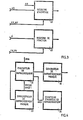
- Figure 1 shows the organization of a memory bank.
- the memory bank consists of a control regulator 1, an assignment register 2, a refresh regulator 3 and a storage sub-assembly 4.
- the control regulator 1 is in communication with the rest of the information processing system, not shown, as well as with the storage sub-assembly 4 in the direction of which it sends control signals C.
- the assignment register 2 communicates the address A of a memory location inside the storage sub-assembly as well as the function F to the control regulator 1.
- the refresh regulator dialogues with the control regulator by exchanging signals CR and supplies the addresses AR of the information to be refreshed to the assignment register.
- the control regulator is shown in Figure 2. It includes a selector-launcher 1.1, an apparent refresh generator 1.2, a memory exciter 1.3, a writer 1.4, a write control generator 1.5, a reader 1.6, a cycle terminator 1.7 and an assignment command generator 1.8.
- the selector-launcher 1.1 receives requests for memory cycles originating from outside the control regulator and requests for refreshment interned in the memory bank originating from the refresh regulator. It decides on the execution of these requests to trigger the operation either of the apparent refresh generator 1.2, or of the writer 1.4 or of the reader 1.6. In all cases, it intervenes in the operation of the assignment command generator 1.8 and of the memory exciter 1.3.
- the apparent refresh generator 1.2 has the function of triggering an apparent refresh cycle, it communicates with the memory exciter. When a refresh cycle is finished, the apparent refresh generator 1.2 controls the end of cycle terminator 1.7.
- the memory exciter 1.3 generates control signals for triggering the memory cycles in the storage subset 4 of FIG. 1.
- the writer 1.4 controls the write actions in the storage subset 4 as a function of 'command issued by the write control generator 1.5.
- the writer 1.4 controls the cycle terminator 1.7.
- the write control generator 1.5 dialogues with the cycle terminator 1.7, supervises the writer 1.4 and commands the selector-launcher 1.1 for the restart of a memory cycle phase.
- the reader 1.6 triggers the read operations in the storage sub-assembly 4 before commanding the cycle terminator 1.7 at the end of the read cycle.
- the cycle terminator 1.7 collects the ends of the various operations executing in the memory bank, and authorizes the new actions of the launcher selector, that is to say new memory cycles.
- the assignment command generator 1.8 commands, under the control of the launcher selector 1.1 and of the cycle terminator 1.7, the assignment register 2 of FIG. 1.
- the assignment register represented in FIG. 3 is broken down into an address register 2.1 and a function register 2.2.
- the address register 2.1 receives the address AD of the sought-after memory location and on the other hand the refresh address AR generated by the refresh regulator. These addresses are recorded inside the register 2.1 to be presented to the storage sub-assembly under the control of the control signals AX, AV emitted by the assignment control generator 1.8.
- the function register 2.2 records the function F which must be executed by the control regulator, under the control of the FX, FV control signals generated by the assignment control generator.
- the refresh regulator is broken down into a refresh driver 3.1, a masked refresh generator 3.2, a masked refresh recorder 3.3, and a refresh address counter 3.4.
- the refresh exciter decides to launch the masked refresh calls to the masked refresh generator 3.2 and the apparent refresh request DRA sent to the launcher selector 1.1, when the results RMEZO and RMEZ1 supplied by the masked refresh recorder do not are not satisfactory, these operations taking place cyclically.
- the masked refresh generator 3.2 controls the execution of the masked refresh cycles in the storage sub-assembly 4.
- the masked refresh recorder 3.3 receives from the memory bank control system the indications of execution of the masked refresh cycles .
- the refresh address counter 3.4 supplies the refresh address AR to the address register of the storage sub-assembly 4, under the control of the progress signal ARX coming from the refresh driver 3.1.
- the storage sub-assembly shown in FIG. 5 includes a command distributor for the memory areas 4.1 and a subset of the memory areas 4.2.
- the command distributor directs the memory command signals from the control system into two memory partitions which constitute the subset of the memory areas.
- the subset of zones of memory contains the memory cells or memory points, the realization of which is carried out using integrated capacitors in "MOS" technology.
- FIG. 6 shows a detailed embodiment of the Selector-Launcher of FIG. 2.
- the device represented in FIG. 6 applies to a memory bank solicited by only two requests for use, one materialized by the DC signals or DES applies for the execution in the memory bank of a useful cycle (reading or writing of information), the other materialized by the signal DRA requests the execution in this same memory bank of a refresh cycle apparent.
- the signals DC, DES and DRA are applied respectively to the input 1 of the AND circuits denoted 1.102, 1.103 and 1.104 in FIG. 2.
- the input 2 of each of these AND circuits receives a validation signal from the output 6 of the 1.101 rocker when a positive transition is applied to input 4 of this rocker. This positive transition is the leading edge of an impulse designated under the name VAX1.
- the AND circuits 1.102 and 1.103 attack from their output 3 the inputs 1 and 2 of the logic circuit OR 1.105. This is connected by its output 3 to input 3 of the rocker 1.108.
- the latter is cascaded with a second rocker 1.110, that is to say by connecting its outlet 5 to the inlet 3 of this second rocker.
- the AND circuits for validating requests 1.102, 1.103 and 1.104 are connected by their output 3 to respective inputs 1, 2 and 3 of the logic circuit OR 1.106.
- the latter delivers on its output 4 the signal SO. It also attacks a delay line 1.107.
- the latter synchronizes the rockers 1.108 and 1.109 on their clock input 4 from its calibrated output 2; it also synchronizes the rockers 1.110 and 1.111 from its calibrated output 4. It resets the output 6 of the rocker 1.101 to zero by applying the pulse from its output 3 to the input 1 of this rocker. It also supplies various calibrated delayed signals S1, S2, S3, S4 and S5 on its respective outputs 5, 6, 7, 8 and 9.
- the logic circuits ET 1.112, 1.113 and 1.114 carry out in the same order the functions following AND logic of these different signals: CR (S3) on output 4 of circuit AND 1.112 receiving C at input 1, R at input 2 and S3 on input 3, C (S3) on output 3 of circuit AND 1.113 receiving C at input 1 and S3 at input 2 and finally CR (S3) on output 4 of the AND circuit 1.114 receiving R at input 1, C at input- 2 and S3 at input 3.
- the logic circuit ET 1.115 delivers the function C (S5 ) on its output 3 from signals C on its input 1 and S5 on its input 2.
- FIG. 7 is a detailed representation of the apparent refresh generator of FIG. 2.
- the Apparent Refresh Generator is energized by the CR signal (S3) from the Selector-Launcher or by the LRA signal from the Cycle Terminator. It triggers the start of an apparent refresh cycle, the control of which in the Storage Sub-Assembly is ensured by the transmission, with suitable synchronization, of the RALZO and RALZl signals.
- the data input 1 of this monostable is validated at work by a signal at logic zero.
- the resistance-capacity network Rl Cl which determines the time constant fixing the duration of the output signal. Resistor Rl being adjustable, it will be possible to adjust this time constant to the appropriate value.
- the output 4 delivers the complemented value of the output signal which is therefore in the form of a negative pulse with adjustable duration. The latter is transmitted under the name SALXO to the Memory Exciter. It is also directed to the clock input 4 of the rocker 1.202 which also receives the logic value zero on its data input 3.
- the trailing edge of the negative pulse is a rising transition which, consequently, activates the rocker 1.202. This will then deliver a negative signal on its output 5.
- This negative signal is transmitted to input 1 of the delay line 1.203 which, after a calibrated delay, reinjects this negative signal from its output 3 on continuous input 1 of rocker 1.202. The latter then carries its output 5 to the logic value one, which interrupts the negative signal emitted on its output 5.
- the output 2 of the delay line 1.203 delivers a pulse with the calibrated delay which, received on input 1 of l 'inverter 1.213 is supplemented at output 2 of this inverter to be directed to the Memory Exciter under the name SACXO.
- the negative pulse constituting the signal of the output 5 of the rocker 1.202 is transmitted under the name BRlXl to the Assignment Control Generator (1.8).
- the output 4 of the delay line 1.203 is connected to the input 1 of the inverter 1.204; this has the effect of showing on output 2 of this inverter a suitably delayed positive pulse which is directed on input 1 of the logic gate OR 1.205.
- This OR circuit also receives on its input 2 the LRA signal from the Cycle Terminator. On its output 3, it delivers a pulse called DRATZ which is transmitted to the refresh exciter.
- This same pulse directed to the clock input 2 of the monostable 1.206, itself controlled to work on its data input 1, causes the appearance of a negative pulse at output 4 of this monostable.
- the duration of this pulse is calibrated by the resistance-capacity network R 2 C 2 , adjustable by its resistance R 2 , wired to input 5 of the monostable 1.206.
- the output 4 of the monostable 1.206 is connected to the clock input 4 of the rocker 1.207 which also receives the logic value zero on its data input 3.
- the trailing edge of the negative pulse coming from the output 4 of the monostable 1.206 will therefore cause the appearance of a negative signal at output 5 of the rocker 1.207.
- the signal is transmitted to input 1 of delay line 1.208.
- the rocker 1.210 receives on its clock input 4 the DRATZ pulse coming from the output 3 of the OR circuit 1.205; its data input 3 is set to logic value zero and it is initialized to logic value zero on its output 6 by means of the signal SALZ accessing its continuous input 1.
- This signal SALZ comes from the Memory Exciter.
- the DRATZ pulse therefore transfers the value logic zero on the output 5 of the rocker 1.210, that is to say the logic value one on the output 6, until the moment of resetting to zero by the signal SALZ.
- the output 6 validates the inputs 1 of the logic circuits ET 1.211 and 1.212 which then emit a true logic value on their output 3 under the names of signals RALZO and RALZ1 if the respective conditions of input RMEZO and RMEZ1 received on their entry 2 are themselves at work.
- the RMEZO and RMEZ1 conditions come from the Hidden Refresh Recorder and the RALZO and RALZl output signals are intended for the Command Distributor for the Memory Zones.
- the Memory Exciter is detailed in FIG. 8. It is excited by means of the synchronization signals SI and S4 coming from the Selector-Launcher. It activates the Storage Sub-Set by means of the Line Address Selection, SAL, and Column Address Selection, SAC control signals.
- the signal S1 from the Selector-Launcher is a positive pulse. It is directed to the input 1 of the inverter 1.301 which therefore delivers a negative pulse on its output 2. This negative pulse attacks the continuous input 1 of the rocker 1.302 which consequently takes the true logic value on its output 5, triggering thus sending the SAL signal to the Order Distributor for the Memory Zones.
- the data input 3 of the rocker 1.302 is permanently brought to the logic value "0"; the trailing edge of the negative SALXO signal from the Apparent Cooling Generator therefore causes a reset of the SAL signal on output 5 of this rocker. Another reset is obtained by setting the continuous input 2 of the signal SALZ.
- This signal comes from the output 2 of the inverter 1.304 whose input 1 is connected to the output 3 of the OR logic circuit 1303.
- the latter receives the general initialization signal Z on its input 2, and, on its input 1, the signal SALTZ coming from the cycle terminator.
- the SALZ signal from output 2 of the inverter 1.304 is also directed to the Apparent Refresh Generator and to the Assignment Command Generator.
- the signal S4 issued with a calibrated delay from the Selector-Launcher attacks input 1 of the inverter 1.305. It thus reappears in supplemented form at output 2 of this inverter to control input 1 of rocker 1.306.
- the latter then carries to the logical value "a" its output 5 which delivers the signal SAC bound for the Distributor of Commands for the Memory Zones.
- the data input 3 of the rocker 1.306 being permanently brought to logical zero, the signal SACXO emitted by the Apparent Cooling Generator causes the reset of the signal SAC of the output 5. Another reset is obtained by the action of the output 2 of the inverter 1.308 on the continuous input 2 of the rocker 1.306.
- the input 1 of the inverter 1.308 is connected to the output 3 of the OR logic circuit 1.307 - which receives respectively on its inputs 2 and 1, the initialization signal Z and the synchronization signal Tl from the Cycle Terminator.
- the Scriptor is detailed in FIG. 9. It triggers the writing action by means of the signal DEC in the Memory Sub-Assembly when this action is requested on the interface by the signal DE and the technological conditions of writing are united. This last control is carried out using the Writing Regulation Generator which communicates with the Scriptor through all 5 of the DES, DESY and DESXO signals.
- the OR 1.411 logic circuit is connected on its input 1 to output 3 of the AND logic gate 1.409 and, on its input 2, to output 3 of the AND logic gate 1.410. These two channels correspond to two different write trigger modes.
- the first trigger channel is carried out through the logic gate ET 1.409 which receives on its input 2 the signal DE coming from the interface through the Write Regulation Generator and on its input 1, the signal displayed by the output 5 of rocker 1.406.
- This rocker is put to work, that is to say at the logical value "one” on its output 5, if its data input 3 was at “one” at the time of the rising transition of the signal C (S5) on its clock input 4. This signal comes from the Selector-Launcher.
- the data input 3 of the rocker 1.406 is connected to the output 3 of the OR logic circuit 1.401 which thus transmits the conditions for putting the rocker 1.406 into work received on its inputs 1 and 2, namely, respectively, the working state of the CYE signal from the Function Register or the working status of the DES signal sent by the Write Regulation Generator.
- the output 3 of the OR logic circuit 1.401 is also connected to the input 1 of the inverter 1.408 which by its output 2 communicates the signal NES to the Reader.
- the rocker 1.406 is put back to rest through the logic tool OR inverter 1.403 whose output 3 is wired to the continuous input 2 of this rocker.
- the inputs 1 and 2 of this logic OR inverter tool 1.403 respectively receive the general initialization signal Z and the pulse from output 2 of the delay line 1.413 of the Scriptor.
- the second trip channel is carried out through the logic circuit ET 1.410 which receives, on its input 2, the control signal DESY generated by the Write Regulation Generator and, on its input 1, the signal coming from the output 5 of rocker 1.407.
- This rocker produces a signal at the logical value "one” on its output 5 when its data input 3 was at "one” during the setting to one of its clock input 4.
- the latter is, as for the rocker 1.406 controlled by the signal C (S5) from the Selector-Launcher.
- Data input 3 of rocker 1.407 is supplied by output 3 of the AND logic circuit 1.404.
- This AND circuit receives the complemented value of the DES signal on its input 1 and the CYI signal from the Function Register (2.2.) On its input 2.
- the output 2 of the inverter 1.402 which admits the DES signal on its input 1 is indeed connected to input 1 of the AND circuit 1.404.
- the rocker 1.407 is reset to zero on its output 5 by the action on its input 2 of the signal generated by the output 4 of the OR-inverter circuit 1.405.
- the OR-inverter circuit 1.405 is itself supplied by the general initialization signal Z on its input 1, by the synchronization signal T2 from the Cycle Terminator on its input 2, and finally, by the pulse from the output 2 of the Scriptor's 1.413 delay line on its input 3.
- the OR 1.411 logic circuit delivers, in both triggering cases, a pulse on its output 3 to, on the one hand, input 1 of the delay line 1.413 and, on the other hand, input 1 of the inverter 1.412.
- the output 2 of the inverter l.4l2 then emits a negative pulse towards the continuous input 1 of the rocker 1.414 whose output 5 is, consequently, set to the true logic value.
- the DEC Write Trigger signal thus generated is sent to the Control Distributor for the Memory Zones.
- the rocker 1.414 is reset to zero by the action on its clock input 4 of the pulse from the output 3 of the delay line 1.413, its data input 3 being permanently wired to the logic value "zero" .
- the complemented value of the general initialization signal Z also sets the output 5 of the rocker 1.414 to zero by action on the continuous input 2 of this rocker.
- Delay line 1.413 also delivers the DESXO and FEC synchronization signals to the Write Regulator and the Cycle Terminator, respectively.
- the Write Regulation Generator or more simply the Write Regulator, is presented in detail in Figure 10. It manages the Write Requests presented in the form of an interface signal DE by the user bodies of the bank of memory. This management of Write Requests is ensured according to the technological availability of the Memorization subset, which only admits triggering of writing under certain very precise chronological conditions.
- the Writing Regulator controls the functioning of the Scripteur with which it communicates by means of the signals DE, DES and DESY.
- the animation of the Writing Regulator depends on all the other sub-organs that surround it.
- This signal C (S3) is thus conditioned by means of this logic gate AND 1.501 by the signal CYI emitted by the Function Register on input 1 and by the signal DES coming from input 3 of output 6 of rocker 1.520 .
- the output 4 of the logic circuit ET 1.501 is connected on the one hand to the input 1 of the monostable 1.502 and on the other hand to the input 1 of the inverter 1.507.
- the signal C (S3) thus triggers the monostable 1.502 and initializes at zero the output 6 of the rocker 1.512 which in fact receives, on its continuous input 1 the signal emitted by the output 2 of the inverter 1.507.
- the duration of the positive signal appearing on output 2 of the monostable 1.502 is calibrated using the Resistance-Capacitance network R C connected to input 5 of this monostable.
- the Resistance R carried out by means of a potentiometer is adjustable and therefore makes it possible to precisely regulate the duration in question.
- the monostable output signal is routed, on the one hand, to input 1 of the inverter 1.506 and on the other hand, to input 3 of the rocker 1.508.
- the output 2 of the inverter 1.506 thus feeds the input 1 of the delay line 1.511 with the signal supplemented by the output signal of the monostable 1.502. This supplemented signal is found at the end of a calibrated delay time on the output 2 of the delay line 1.511 in order to excite the clock input 4 of the rocker 1.512.
- the 1.503 OR-inverter logic circuit is itself actuated on its input 1, by the signal DL from the Cycle Terminator (1.7), on its input 2, by the general initialization signal Z and on its input 3, by the output 3 of the logic circuit ET 1.504 which itself conditions the signal AEETZ presented at its input 1 and coming from the Cycle Terminator by the signal injected on its input 2 by the output 5 of the rocker 1.509.
- the rocker 1.508 receives, as we have seen, on its data input 3 the direct signal generated by the monostable 1.502. It is consequently triggered by the interface signal DE wired to its clock input 4 if the upward transition of this signal DE takes place during the duration of the signal coming from the monostable 1.502. In this case, the output 5 of the rocker 1.508 is set to the logic "a" value and communicates this logic level to the data input 3 of the rocker 1.509. This true level will itself be transferred back to the output 5 of the rocker 1.509 by the action of the signal from the output 2 of the delay line 1.510 on the clock input 4 of this rocker.
- the delay line 1.510 receives on its input 1, the interface signal DE which thus ensures itself, by means of this mechanism, its autosynchronization with respect to the output signal of the monostable 1.502.
- the output 6 of the rocker 1.509 takes by definition the value complemented by that of the output 5 of this rocker which emits the signal DESY towards the Scripteur.
- the rockers 1.508 and 1.509 are reset to the logic value "zero" on their output 5 by action on their continuous input 2 of the signal coming from the output 3 of the OR-inverter circuit 1.505.
- the latter receives the DESYTZ signal from the Cycle Terminator on its input 1 and the general initialization signal Z on its input 2.
- the output 6 of the rocker 1.509 conditions the data input 3 of the rocker 1.515 and the output 6 of the rocker 1.512 is connected to the clock input 4 of the rocker 1.515. Consequently, if the signal coming from the output 6 of the rocker 1.509 is at the true logic value at the time of the arrival of the signal delivered by the output 6 of the rocker 1.512 on the clock input 4 of the rocker 1.515, this rocker 1.515 produces the positive signal called TX on its output 5. This TX signal is intended for the Cycle Terminator (1.7). It is issued until reset of output 5 of rocker 1.515 by action of output 3 of the OR-inverter logic tool 1.516 on continuous input 2 of rocker 1.515.
- the logic tool 1.516 is itself controlled by the general initialization signal Z on its input 1 and by the signal TXTZ coming from the Terminator of Cycles on its input 2.
- the output 6 of the rocker 1.509 also conditions the data input 3 of the rocker 1.513. The latter is triggered if the signal arriving at its data input 3 is at the logic value "one" when the output 6 of the rocker 1.512 delivers a positive signal on the clock input 4 of this rocker 1.513 to which it is connected .
- the output 5 of the rocker 1.513 then takes the logic value "one” and communicates it to the input 1 of the AND logic circuit 1.517.
- output 3 will also take the logic value "one”.
- a working signal to a logical "one” will then be transmitted on the one hand to input 1 of the delay line 1.519 and on the other hand, to input 1 of the inverter 1.518.
- this working signal has the effect of resting the rocker 1.513, that is to say to "zero", the output 5 of this rocker, by propagating in the appropriate polarity from the output 2 of the delay line 1.519 on the input 1 of the OU-reversing tool 1.514 then, from the output 4 of this tool on the continuous input 2 of the rocker 1.513.
- the reset of this 1.513 rocker is also obtained by applying signals to inputs 2 or 3 of the 1.514 OU-inverter circuit. These signals are either the general initialization signal Z on input 2 of circuit 1.514, or the signal DL coming from the interface through Cycle Terminator 1.7 and wired on input 3 of circuit 1.514.
- the output 2 of the 1.518 inverter is connected to the continuous input 1 of the 1.520 rocker.
- the previous work signal therefore also causes the DES signal on output 5 of rocker 1.520 to be set to logic value "one".
- This DES signal is used in the Selector-Launcher (1.1) and the Scriptor (1.4).
- the DES signal is reset to zero by the action of the DESXO signal from the writer (1.4) on the clock input 4 of the rocker 1.520, a permanent logic "zero" being wired to data input 3 of this rocker.
- the general complemented initialization signal Z also provides an initial reset of the DES signal by action on the continuous input 2 of the rocker 1.520.
- the Reader or Reading Exciter is shown in detail in FIG. 11. It is implemented at the prompt of the Selector-Launcher by means of the signal C (S3). It triggers the read action in the Storage subset using the DLE signal.
- Signal C (S3) from the Selector-Launcher activates input 2 of the logic circuit ET 1.601 conditioned on its input 1 by the signal NES developed in the Scriptor.
- the output 3 of the AND logic gate 1.601 is connected to the inputs 2 of the monostables 1.602 and 1.603.
- the inputs 1 of these monostables are permanently validated by means of a constant level at logic "zero" (internally inverted).
- the signal from output 3 of AND gate 1.601 therefore causes these monostables to be triggered, which then deliver a negative pulse on their output 4.
- the durations of these pulses from monostables 1.602 and 1.603 are calibrated respectively by the resistance-capacitance networks (R I , C l ) and (R 2 , C 2 ) wired to the inputs 5 of these monostables.
- the resistors R 1 and R 2 are adjustable, which allows the pulse durations to be adjusted precisely.
- the outputs 4 of the monostables 1.602 and 1.603 are respectively connected to the clock inputs 4 of the rockers 1.604 and 1.605. Since the data input 3 of these rockers is fixed at logic "zero", the trailing edge of the pulses from the monostables therefore causes the output 5 to be "zero" and the output 6 of these outputs to be "one" rockers.
- the resistance networks (R 3 , R 4 ) on the one hand on the continuous input 2 of the rocker 1.604 and (R 5 , R 6 ) on the other hand on the continuous input 2 of the rocker 1.605 guarantee the level of rest ("a" logic) during operation.
- the outputs 6 of the rockers 1.604 and 1.605 respectively validate the inputs 1 and 2 of the AND logic circuit 1.606.
- the output 3 of this logical AND tool is then put to a logical "one" when the two inputs 1 and 2 are at work.
- Input 1 of delay line 1.607 connected to output 3 of circuit 1.606 is then energized and the DLE signal is then delivered to the subset of Memory Zones.
- the output 2 of the delay line 1.607 then retransmits with a calibrated delay, at the input 1 of the tool 1.608 the signal injected on the input 1 of this line. This has the effect of resetting the signal of output 6 of rockers 1.604 and 1.605 and therefore of calibrating the duration of this signal.
- the general initialization signal Z on input 2 of the OR-inverter tool 1.608 ensures initial zeroing of output 6 of rockers 1.604 and 1.605.
- the delay line 1.607 also generates on its output 3 the signal FLE for the use of the Cycle Terminator.
- the Cycle Terminator (or Reset Operator) is detailed in Figure 12.
- the essential function of the Cycle Terminator is to prepare the relaunch of a new memory cycle by resetting the Selector-Launcher by means of the signal VAX1.
- the Cycle Terminator is implemented using the signals indicating the end of elementary operations coming from different sub-organs, such as the signals, FEC from the Scriptor, FLE from the Reader or FRA from the Apparent Refresh Generator.
- the output 5 of the logical OR tool 1.702 excites the input 1 of the delay line 1.705, controls the input 2 of the logical AND tool 1.704 and supplies the signal SALTZ to the sub-organs (1.3) and (3.1) that is, the Memory Exciter and the Refresh Exciter respectively.
- Delay line 1.705 delivers directly from its outputs 2 and 4 the synchronization pulses T1 and T2 suitably delayed, destined for the memory exciter and the masked refreshment recorder respectively and on the other hand from the Scripteur.
- the output 3 of the delay line 1.705 controls the input 2 of the AND tool 1.706, the output 5, the input 2 of the AND tool 1.707, the output 6, the clock input 4 of the rocker 1.712 , output 7, input 1 of tool ET 1.709 and finally output 8, input 2 of logic circuits ET 1.710 and 1.711.
- the signal generated by output 8 of the delay line 1.705 takes the name DESYTZ to supply the Write Regulator.
- the logic circuits ET 1.704, 1.706 and 1.707 are all conditioned on their input 1 by the signal C coming from the Selector-Launcher. They respectively produce on their output 3 the signals AEETZ for the benefit of the Write Regulator, ATCA for the use of the Assignment Command Generator and TXTZ also intended for the Write Regulator.
- the Apparent Refresh End signal FRA also attacks input 1 of the logic OR tool 1.703, the output 3 of which is connected to the continuous input 1 of the rocker 1.708.
- the general initialization signal Z feeds input 2 of the OR 1.703 tool.
- the output 5 of the switch 1.70g conditions the input 1 of the logic circuit AND 1.710 which will deliver on its output 3 the signal VAXl for the benefit of the Selector-Launcher.
- the output 6 of the rocker 1.708 conditions the input 1 of the AND circuit 1.711 and the input 2 of the AND circuit 1.709.
- the logic circuit ET 1.711 will produce on its output 3 the signal LRA intended for the Apparent Cooling Generator.
- the logic circuit ET 1.709 will generate on its output 3 the signal BR2X1 supplied to the Assignment Control Generator.
- the rocker 1.712 On reception on its clock input 4 of the synchronization signal coming from the output 6 of the delay line 1.705, the rocker 1.712 presents an output signal to the logical value "one" on its complemented output 6, since its data input is fixed at the logical value "zero".
- the output 6 of the rocker 1.712 is connected to the input 1 thus validated of the logic circuit AND 1.714.
- the interface signal DL which is redirected to the Writing Regulator puts to work at the logic value "one” on its complemented output 6 the rocker 1.713 by actuating the clock input 4 of this rocker, l data input of this same device being brought by wiring to the constant logic value "zero".
- the output 6 of this rocker 1.713 is connected to the input 2 of the AND logic circuit 1.714 which is thus completely validated and then delivers on its output 3 the signal ALCA intended for the Assignment Command Generator.
- the output 3 of the logic circuit AND 1.714 also debits on the input 1 of the delay line 1.715, which generates at the end of a calibrated delay a positive signal on its output 2.
- This output 2 attacks the input 1 of the 1.716 OU-reversing logic tool which, by action of its output 3 on their continuous input 1, resets the rockers 1.712 and 1.713.
- the general initialization signal Z on the input 2 of the OR-inverter tool 1.716 likewise provides the initial "zeroing" of the outputs 6 -of these same rockers 1.712 and 1.713.
- FIG. 13 gives a detailed representation of the Assignatson Command Generator.
- This sub-body has the function of developing the commands of the assignment registers, that is to say the commands on the one hand, of the Address Register, and on the other hand, of the Function Register. These assignment commands must be carried out under the general control of the Command Regulator. This is why the Assignment Control Generator is one of the sub-organs of this assembly to which it is internally interconnected, more particularly to the Selector-Launcher, and to the Terminator.
- the Selector-Launcher presents the signal C (S3) on input 1 of the inverter 1.801.
- the output 2 of this tool 1.801 injects a negative pulse on the input 1 of the rockers 1.802, 1.806 and 1.807 to thus communicate to them the true logic state on their output 5 and therefore the false logic state on their output 6.
- the Selector - Launcher (1.1) also provides the signal SO on the clock input 4 of the rocker 1.808 and on the input 2 of the logic tool OR 1.812, which has the effect of putting the rocker 1.808 in the logic state "zero" on its output 5 and therefore in logic state "one” on its complemented output 6.
- the data input 3 of the rocker 1.808 is put to "zero” permanently by wiring a mass, which causes the transfer of the logic value "zero” in direct output 5 on any positive clock transition.
- the application of the signal SO on the input 2 of the OU 1.812 tool causes the output 4 of this tool to pass to the logical level "one", thus generating the AV signal for the benefit of the Address Register.
- the Cycle Terminator delivers the signals ATCA, ALCA and Tl.
- the first ATC ⁇ signal directed on the clock input 4 of the rocker 1.802 will have the effect of putting the latter in the logic state "one" on its complemented output 6, by transfer of zero to its direct output 5 as we saw previously.
- the output 6 of the rocker 1.802 is wired to the input 1 of the AND logic circuit 1.805 which receives the signal ALCA on its input) 2.
- the output 3 of this tool AND activates the clock input 4 of the rockers 1.806 and 1.807.
- the signal Tl in turn feeds the input 1 of the logic gate OR inverter 1.803, the other input 2 of which receives the general initialization Z.
- the output 3 of this circuit OR inverter 1.803 attacks 3 the continuous input 1 of the rocker 1.808 , which aims to put the latter in the logical state "one" on its direct output 5.
- the output 5 of the rocker 1.808 is connected to the input 2 of the AND circuit 1.811 which receives on the other hand on its input 1 the output 6 of the rocker 1.806.
- This same output 6 of the rocker 1.806 is directed under the name FX to the Function register.
- the output 3 of the logic gate ET 1.811 takes the name AX for the Address Register.
- the OR logic circuit 1.812 receives on its input 1 the output 5 of the rocker 1.807 also connected under the name FV to the Function Register; it receives on its input 3 the output 6 of the rocker 1.808 and as we have already seen on its input 2, the signal SO.
- the output 4 of the logic OR circuit 1.812 is directed under the name AV to the Address Register.
- the Assignment Control Generator also includes the two rockers 1.809 and 1.810.
- the first of these rockers rated 1.809 is initialized or reset to "zero" on its complemented output 6 using the logic tool OR inverter 1.804, the output 3 of which activates the continuous input 1 of this rocker.
- the logic OR switch gate 1.804 itself receives on its input 1 the signal FRA coming from the Apparent Cooling Generator and the general initialization signal Z on its input 2.
- the same rocker 1.809 is put to work, at the logic value " a "on its complemented output 6 by application to its clock input 4 of the signal BR2Xl coming from the Cycle Terminator or by application to its continuous input 2 of the signal BR1X1 coming from the Apparent Refresh Generator.
- the output 6 of the rocker 1.809 communicates its logic level "one" to the two logic tools OR 1.813 and 1.814 by wiring on their input 1.
- the outputs 3 respectively BRZ0 and BRZ1 are intended for the Address Register.
- Tool 1.813 also receives the signal Az on its input 2
- tool 1.814 receives the signal Az on input 2.
- These last two signals are provided by the Address Register.
- the 1.810 rocker is initialized or reinitialized by application on its continuous input 1 of the signal SALZ coming from the Memory Exciter; it then takes the logical value "zero" on its complemented output 6 directed under the name BAC in the Address Register. It is put to work with BAC at the logical value "one” by application on its clock input 4 of the signal S2 coming from the Selector-Launcher.
- FIG 14 shows a representation of the Address Register.
- the address register transforms the address signals ADz, ADr or ADr + p appearing on the interface into selection signals for the memory areas. To do this, it performs two main functions: a storage function executed in an original lock system and a multiplexing function between the effective addresses and the refresh addresses noted AR r from the Refresh Address Counter (3.4).
- the Address Register operates under the control of the Assignment Command Generator (1.8) from which it receives the AX, AV, BRZO, BRZ1 and BAC command signals.
- the selection signals intended for the memory zones (4.2) are denoted A r ZO or A r Zl according to their assignment zones, zone 0 or zone 1.
- the signal Az and its value .complemented Az supplies for their part, the Distributor Control for Memory Zones (4.1), the Hidden Refresh Generator (3.2) and the Hidden Refresh Recorder (3.3).
- the address index z is a particular value of the rank of the binary address digits, the choice of which will be specified below.
- the addresses of index r or r + p correspond to the bina: .res of address to be multiplexed between them to enter successively during the same cycle in the "MOS" memory cells. These same binary digits are also to be multiplexed with the refresh addresses.
- the number of binary digits represented by the index r or the index r + p depends on the type of "MOS" cells and in fact on its capacity. As an indication, a "MOS" cell of 16K binary digits will use 7 addresses of indices r and 7 addresses r + p, ie 14 binary digits in total. There will be as many storage cells of which only two are represented in FIG. 14, one for the index r and one for the index r + p. These memory cells of the address register as well as that which stores the address of index z are all presented in the same way.
- An AND circuit rated according to case 2.101, 2.102, or 2.103 conditions the address entering at 1 coming from the interface by the cable signal at 2 ensuring the AX transfer command.
- An OR circuit 2.104, 2.105 or 2.106 receives on its input 2 the output 3 of the previous AND circuit. It supplies via its output 3 the input 1 of another AND circuit 2.107, 2.108 or 2.109 conditioned on its input 2 by the AV locking control signal. The output 3 of these latter circuits feeds the input 1 of the preceding OR circuit.
- a second OR circuit rated 2.110, 2.111 or 2.112 is mounted in parallel on the first; their peer inputs 1 or 2 are linked together. Thus input 1 of circuit 2.110 is connected to input 1 of circuit 2.104 and so on.
- the locking circuit constituted by tools such as the OR circuit 2.104 and the AND circuit 2.107 is thus ensured the maximum speed, the charges being transferred to the OR tool in parallel such as 2.110.
- the output 3 of the logic OR tool 2.110 directly delivers the signal A z and feeds on the input 1 the inverter 2.113 which produces on its output 2 the complemented signal A Z.
- the output 3 of the OR circuits 2.111 and 2.112 respectively attacks on the one hand the input 1 of the multiplexers four channels 2.114 and 2.115 and on the other hand, input 2 of these same multiplexers.
- Inputs 3 and 4 of these multiplexers receive the AR r Refresh Address signals.
- Inputs 1, 2, 3 and 4 of the multiplexers are data inputs.
- the control input 5 (dimensioned CO) receives respectively the signals BRZO and BRZl, BRZO on the tool 2.114 assigned to zone O and BRZl on the tool 2.115 specific to zone 1.
- the command dimensioned CO) BRZO or BRZ1 switches all the inputs of. data (1 and 2) on all the data inputs (3 and 4) both receiving the refresh address AR r .
- the output 7 of the multiplexers 2.114 and 2.115 respectively delivers the signals ArZ0 and ArZl corresponding to the zones ZO and Zl in which they operate.
- the control input 6 (rated C1) of the two multiplexers 2.114 and 2.115 is assigned to the common signal BAC which switches the data inputs 1 to the data inputs 2 of these multiplexers.
- Figure 15 shows a representation of the Function Register.
- the function register stores the write (DE) and read (DL) order signals presented by the interface. For this, it implements locks of the same type as those of the address register.
- the function register locks operate under the control of the FX and FV control signals from the assignment control generator (1.8). From the stored values, the function register also generates the condition signals CYE, CYI, CYL which are used in various sub-organs of the memory bank Control Regulator.
- the OR 2.207 and 2.208 logic circuits as well as the 2.209 and 2.210 OR OR logic tools are mounted in parallel on the OR 2.203 and 2.204 logic gates respectively.
- the inputs 1 of the three circuits 2.203, 2.207 and 2.209 are connected together and the same is true of the inputs 2.
- the logic circuits ET 2.211, 2.212 and 2.213 generating the condition signals are then wired to these tools in parallel.
- the AND logic gate 2.211 receives on its input 1 the recorded write order coming from the output 3 of the OR circuit 2.207 and on its input 2 the value supplemented by the recorded read order coming from the output 3 of the inverter OR circuit 2.210. On its output 3, it produces the CYE Write Cycle condition signal intended for the writer (1.4).
- the AND logic gate 2.212 collects, on its input 1, the value supplemented by the recorded write order supplied by the output 3 of the OR inverter circuit 2.209 as well as, on its input 2, the value supplemented with the recorded order of reading produced by output 3 of the OR circuit inverter 2.210.
- the AND logic gate 2.213 performs the intersection of the recorded read and non-write signals (value supplemented by that of write) coming from the output 3 respectively of the logic OR circuit 2.208 and of the logic OR inverter 2.209 circuit. It receives these signals on its inputs 1 and 2 respectively. It thus delivers the CYL Read Cycle condition signal for use by Cycle Terminator (1.7).
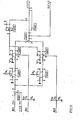
- FIG. 16 represents the Refreshment Exciter of FIG. 4. It comprises a clock generator composed of the monostables 3.101 and 3.102 mounted in multivibrator and the switching times of which are adjustable as a function of the two time constants R 1 Ci and R 2 C 2 inserted in each of the circuits of the two monostables.
- the monostable 3.101 delivers the signal Dl to input 3 of the rocker 3.106.
- This signal D l is memorized by the rocker 3.106 on arrival at its input 4 of the signal delivered by the output 4 of the AND gate 3.103 which receives, on its input 1 the SALTZ signal emitted by the output 5 of the OR gate 1.702 of the cycle terminator, on its input 2, the RME signal emitted by the output 2 of the inverter 3.104 whose input 1 receives the RME signal emitted by the output 3 of the AND gate 3.312 of figure 18 meaning that a masked refresh has been executed, on its input 3 the signal emitted by the output 6 of the rocker 3.107.
- the rocker 3.107 is connected by its input 3 to the output 5 of the rocker 3.106, it copies on its output 5 the state of the rocker 3.106 when the signal emitted by the output of the AND gate 3.103 is transmitted on its input 4 through the adjustable delay line 3.108.
- the output 5 of the rocker 3.107 delivers the masked ARM refresh authorization signal to the input 1 of the AND gate 3.201 of the masked refresh generator and to the input 2 of the AND gate 3.301.
- Inputs 2 of rockers 3.106 and 3.107 are reset to zero by output 4 of gate OR 3.109 which receives, on its input 1, the FRM signal for the end of masked refresh issued by output 4 of gate AND 3.309 of the masked refresh recorder, on its input 2 the signal FRA of end of apparent cooling emitted by the output 2 of the inverter 1.209 of the apparent cooling generator and on its input 3 the signal Z of general initialization.
- the signal D 1 is emitted by the output 4 of the monostable 3.101 towards the clock input 4 of the rocker 3.112 whose input 3 is placed at ground potential.
- the output 6 of the rocker 3.112 is connected on the one hand to the input 1 of the adjustable delay line 3.113 and to the clock input 4 of the rocker 3.110.
- the delay line 3.113 retransmits an instant later, on its output 2 the signal that it received on its input 1, towards the input 1 of the inverter 3.114 whose output 2 is connected to the inverting input 1 of the tipper 3.112.
- the rocker 3.112 is reset to zero on the arrival of the signal D l and returns to the logical state 1 when the state taken by the output 6 of the rocker 3.112 has been recovered on the output 2 of the delay line 3.113.
- This state is also transmitted an instant later by the output 3 of the delay line towards the clock input 4 of the rocker 3.111 and another instant later by the output 4 of the delay line 3.113 towards the input 2 of the AND gate 3.116.
- the executed masked refresh signal RME applied to the input 3 of the rocker 3.110 is thus successively transmitted to the outputs 5 of the rockers 3.110 and 3.111 connected in cascade.
- the output 5 of the rocker 3.111 is connected to the input 1 of the AND gate 3.116 which thus emits on its output 3 the signal RMEZ to reset the masked refresh signal to zero towards the input 1 of the OR gate 3.307 of the hidden refresh recorder.
- the RMEZ signal is also transmitted to input 2 of the OR gate 3.115, the other input 1 of which receives the signal FRA of the end of apparent refreshment emitted by output 2 of the inverter 1.209 of the apparent refresh generator.
- the OR gate 3.115 thus generates by its output 3 the signal ARX of order to switch to the refresh address when the signal RMEZ is present or when the signal FRA is emitted by the apparent refresh generator.
- the "OU-NON" circuit 3.105 receives on its input 1 the signal DRATZ of reset time of. apparent cooling emitted by the output 3 of the OR 1.205 circuit of the apparent cooling generator and on its input 2 the signal Z of general initialization, its output 3 is connected to the input 1 of the rocker 3.117.
- the output 6 of the rocker 3.111 is connected to the clock input 4 of the rocker 3.117.
- the rocker 3.117 is connected to the ground potential by its input 3 and emits on its output 6 the signal DRA towards the input 1 of the AND gate 1.104 when the rocker 3.111 takes the state 0 on the direct output 5.
- Figure 17 shows the Hidden Refresh Generator. It includes a monostable 3.202 triggered on its input 2 by the signal appearing on the output 3 of the AND gate 3.201 which receives on its input 1 the ARM signal of authorization of refreshed mask coming from the output 5 of the rocker 3.107 of the exciter and on its input 2 the synchronization signal Sl.
- the output 4 of the monostable 3.202 is applied to the clock input 4 of the rocker 3.203 whose input 3 is connected to the ground potential and whose output 5 is connected to the input 1 of the delay line 3.204.
- the delay line 3.204 is connected on its intermediate output 2 to the input 1 of the rocker 3.203. At rest, rocker 3.203 is in logic state 1, it does not takes the logic 0 state only during the transmission time of the falling edge of the signal present on its output 5 through the delay line 3.204.
- the output 6 of the rocker 3.203 is connected to the input 2 of the logic circuit "OR NOT” 3.205 which receives on its second input 1 the general signal Z of initialization.
- the output 3 of the "OR NOT” circuit 3.205 is connected to the input 1 of the rocker 3.206 which receives on its clock input 4 the signal emitted by the output 3 of the "AND” gate 3.201.
- the output 6 of the rocker 3.206 is connected, on the one hand to the input 1 of the AND gate 3.207 and on the other hand to the input 1 of the AND gate 3.208, it takes the logic 1 state when a signal is transmitted by output 3 of AND gate 3.201.
- the AND gate 3.207 receives on its input 2 the signal A z making it possible to designate a particular zone ZO of the storage device and on its input 2 the signal RMEZO signaling that a masked refresh is not executed in the zone ZO, it transmits on its output 4 the signal RMLZO bound for the OR gate 4.108 of the control distributor for the memory zones to start a masked refresh in zone O.
- the AND gate 3.208 receives on its input 2 the signal Az to designate a zone Zl of the storage device and on its input 3 the signal RMEZ1 signaling that a masked refresh is not executed in zone 1, it emits on its output 4 the signal RMLZ1 intended for input 2 of the circuit OR 4.109 of the control distributor for the memory zones to initiate a masked refresh in zone 1.
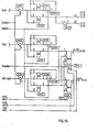
- Figure 18 shows the Hidden Refresh Recorder which aims to control the execution of the masked refresh cycles in the storage subset. It mainly consists of rockers 3.305 -3.306 and the delay line 3.308.
- the clock inputs 4 of the rockers 3.305 and 3.306 receive the signal T1 sent by the delay line 1.705 of the cycle terminator. This signal T1 is also transmitted to input 1 of the delay line 3.308, the output 2 of which is connected to input 1 of the AND gate 3.309.
- the input 3 of the rocker 3.305 is connected to the output 3 of the OR circuit 3.303 whose input 1 is connected to the output 3 of the AND gate 3.301 and the input 2 to the output 5 of the rocker 3.305.
- the AND gate 3.301 receives, on its input 2 the masked ARM refresh authorization signal emitted by the output 5 of the rocker 3.107 of the refresh exciter and on its input 1 the signal Az allowing the addressing of zone 1 of the memorization unit.
- rocker 3.306 is connected to output 3 of the OR circuit 3.304 which receives on its input 1 the signal emitted by output 3 of AND gate 3.302 and on its input 2 the signal emitted by output 5 of rocker 3.306.
- the AND gate 3.302 receives on its input 1 the signal Az allowing the addressing of zone 0 of the storage unit and on its input 2 the masked ARM refresh authorization signal.
- the inputs 2 of the rockers 3.305 and 3.306 are controlled by the output 4 of the gate OR inverter 3.307 which receives, on its input 1 the signal RMEZ for resetting to zero the masked refresh signal executed emitted by output 3 of the AND gate 3.116 from the refresh exciter on its input 2 the signal FRA of the end of apparent refreshment emitted by the output 2 of the inverter 1.209 of the apparent refresh generator and on its input 3 the signal Z of general initialization.
- the AND gate 3.309 is connected by its input 3 to the output 5 of the rocker 3.305 and by its input 2 to the output 5 of the rocker 3.306, it delivers on its output 4 the signal FRM of end of refreshment masked intended for the input 1 of door "YES-NO" 3.109 of the cooling exciter.
- the AND gate 3.312 is connected by its input 1 at the output 5 of the rocker 3.306 and by its input 2 at the output 5 of the rocker 3.305, it transmits on its output 3 the RME masked refresh signal executed at the input of the refresh exciter.
- the states of the outputs 5 of the rockers 3.305 and 3.306 are inverted through the inverters 3.310 and 3.311 which respectively transmit the signal RMEZO to input 2 of the gate AND 1.211 and the signal RMEZ1 to input 2 of the gate AND 1.212 of the apparent refresh generator.
- FIG. 19 represents the Refresh Address Counter which supplies the refresh address AR to the address register under control of the progress signal ARX coming from the refresh driver. It consists of two counters 3.401 and 3.402 connected in series. The output 6 of the counter 3.401 being connected to the input 1 of the counter 3.402. The bits of the refresh address AR o to AR 2 appear respectively on outputs 3, 4, 5 of the counter 3.402 (most significant) while the refresh bits AR 3 to AR 6 appear respectively on outputs 2, 3, 4, -5 from counter 3.401.
- Figure 20 shows the Command Distributor for Memory Zones. It mainly consists of OR circuits 4.108 and 4.109 as well as AND circuits 4.106, 4.107, 4.103 and 4.104.
- the input 1 of the OR circuit 4.108 is connected to the output 3 of the AND gate 4.105 which receives on its input 1 the signal SAL of line address selection coming from the output 5 of the rocker 1.302 of the memory exciter and on its input 2 the signal coming from the inverter 4.101 whose input is excited by the signal Az for selecting zone 1 of the memory.
- Input 2 of the circuit OR 4.108 receives the RMLZO signal emitted by output 4 of gate AND 3.207 of the masked refresh generator.
- Input 3 of OR gate 4.108 receives the RALZO signal from the apparent refresh generator and signifying that an apparent refresh has been started in zone 0.
- Output 4 of OR gate 4.108 delivers the CALZO signal to the sub- set of memory zones for controlling the line address in zone O.
- the OR circuit 4.109 is connected by its input 1 to output 3 of the AND gate 4.102. This receives the signal SAL on its input 1 and the signal Az on its input 2. Input 2 of circuit 4.109 receives the masked refresh signal RMLZl launched in zone 1 of the memory coming from the refresh generator. The input 3 of circuit 4.109 receives the signal RALZ1 of apparent refreshment launched in zone 1 of the memory and coming from the apparent refreshment generator. The OR circuit 4.109 delivers on its output 4 the signal CALZ1 for command to select the line address of zone 1 of the memory, this signal is transmitted to the storage sub-assembly.
- the AND gate 4.106 receives on its input 1 the signal SAC for column address selection sent by the output 5 of the rocker 1.306 of the memory exciter and on its input 2 the signal sent by the inverter 4.101 transmitting the signal A z .
- the output 3 "of the AND gate 4.106 then transmits the signal CACZO of command to select the address of the column column of zone O to the subset of the memory zones.
- the AND gate 4.107 receives, on its input 1 the command signal write transmitted by the output 5 of the rocker 1.414 and on its input 2 the signal A z .
- the output 3 of the AND gate 4.107 transmits the write command in zone O CECZO to the subset of the memory zones.
- the AND gate 4.103 is supplied by the signal SAC on its input 1 and by the address A z on its input 2.
- the output 3 of the AND gate 4.103 transmits the signal CACZ1 for controlling the column address selection in zone 1 in the subset of memory zones.
- the AND gate 4.104 receives on its input 1 the signal DEC and on its input 2 the signal A z , it transmits on its output 3 the signal CECZ1 for command to write in zone 1 to the memory subset.
- Figure 21 shows the Subset of Memory Zones. It is made up of the memory blocks 4.210 and 4.211 representing the zones Zo and Z 1 respectively .
- Block 4.210 receives on its input 1 a data bit Dq transmitted by the output 2 of the inverter 4.201 and on its inputs 2 to 8 the address bits of the zone 0, Ar 1 ZO to Ar 7 ZO transmitted by the address register.
- Inputs 9, 10, 11 are connected to the respective outputs of inverters 4.203 to 4.205 transmitting signals CALZO for line address control, CACZO for column address control and CECZO for write control transmitted by the zone control distributor of memory.
- Block 4.211 also receives on its input 1 the data bit Dq transmitted by output 2 of the inverter 4.201 and on its inputs 2 to 8 the address bits of zone 1, Ar 1 Z 1 , at Ar 7 - Z 1 transmitted by the address register.
- the inputs 9, 10, 11 are connected to the respective outputs of the inverters 4.207 to 4: 209 transmitting the signals CALZ1 for line address control CACZ1 for column address control, CECZ1 for write control coming from the zone control distributor of memory.
- the rockers 1.110 and 1.111 of the Selector-Launcher present the logical configuration CR. Only, the logic tool ET 1.114 of the Selector-Launcher therefore delivers a CR pulse (S3) intended for the Apparent Refresh Generator (figure 7). At this sub-organ, this pulse C R (S3) triggers the monostable 1.201. The trailing edge of the signal from the complemented output of this monostable will reset to zero under the name SALXO the switch 1.302 for selecting line addresses located at the level of the Memory Exciter (figure 8). This is the cancellation of the first technological action launched prematurely in this case, as if it had been a useful cycle.
- the time constant of the monostable 1.201 (FIG. 7) is calibrated so as to ensure the lowest possible duration of this technological action compatible with the constraints of using "MOS" circuits.
- the rocker 1.202 and the delay line 1.203 transform the trailing edge of the SALXO signal into a pulse which, transmitted under the BR1X1, excites the commands to connect to the refresh addresses BRZO and BRZ1 in the Assignment command generator (figure 13 ). These commands are executed by switching the 4-channel multiplexers 2.114 and 2.115 in the Address Register in Figure 14. This therefore constitutes the preparation for the refresh execution phase which will be launched later.
- the entire device consisting of the monostable 1.206, the rocker 1.207, the delay line 1.208 and the inverter 1.209 ensures the creation of the FRA pulse.
- the trailing edge of the calibrated duration signal of the complemented output of the monostable 1.206 is transformed into pulse by the delay line switch assembly 1.207 and 1.208.
- the signal FRA causes the end of the cycle by triggering the Cycle Terminator, which, on the one hand returns the SALZ pulse to reset the rocker 1.210 to "zero" and thus cancel the technological action of Refreshment and on the other hand, resets the Selector-Launcher for a new cycle by action of the VAX1 signal.
- the Cycle Terminator is shaken, the ET 1.710 logic tool is inhibited by output 5 of the toggle switch 1.708 and the reset signal VAX1 is not delivered. The control unit is not released for a new cycle.
- the ET 1.711 tool is validated by output 6 of the rocker 1.708 and the LRA signal is sent to the Apparent Cooling Generator (figure 7). There, it triggers on the OR 1.205 tool the execution of a Refresh by applying the procedure described above for the execution phase of an exclusive "Refresh". The switching to the refresh addresses will have been ensured previously in the Cycle Terminator by the creation of BR2X1 pulse on tool ET 1.709 validated by output 6 of rocker 1.708.
- the FRA signal is emitted by the Refresh Generator to energize the Cycle Terminator.
- the rocker 1.708 in its resting state, to "one" on the direct output 5, and to "zero” on the output 6. This will have the effect this time of allowing the pulse of resetting VAX1, which completes the mixed cycle (C, R) by preparing the Selector-Launcher for a new cycle.
- the BR2XI and LRA signals are not emitted since they are invalidated by output 6 at "zero" of the 1.708 rocker.
Landscapes
- Engineering & Computer Science (AREA)
- Microelectronics & Electronic Packaging (AREA)
- Computer Hardware Design (AREA)
- Theoretical Computer Science (AREA)
- Physics & Mathematics (AREA)
- General Engineering & Computer Science (AREA)
- General Physics & Mathematics (AREA)
- Dram (AREA)
Abstract
Le procédé consiste à lancer simultanément les phases de sélection et d'exécution d'un cycle utile à l'intérieur du banc de mémoire au début de chaque cycle mémoire puis à arrêter l'exécution du cycle utile à la fin de la phase de sélection pour enchaîner sur un cycle de rafraîchissement si durant la phase de sélection une opération de rafraîchissement a été sélectionnée. Le séquenceur comprend d'une part un régulateur de commande 1 en communication avec un système de traitement d l'information et un sous-ensemble de mémorisation 4 et d'autre part un régulateur de rafraîchissement 3 en liaison avec un registre d'assignation 2 et un régulateur de commande 1.The method consists in simultaneously launching the selection and execution phases of a useful cycle inside the memory bank at the start of each memory cycle and then stopping the execution of the useful cycle at the end of the selection phase. to continue on a refresh cycle if during the selection phase a refresh operation has been selected. The sequencer comprises on the one hand a control regulator 1 in communication with an information processing system and a storage sub-assembly 4 and on the other hand a refresh regulator 3 in connection with an assignment register 2 and a control regulator 1.
Description
La présente invention concerne un procédé de rafraîchissement d'un banc de mémoire à cellules capacitives, ou circuits "MOS", et le séquenceur de rafraîchissement correspondant applicables aux systèmes de traitement de l'information.The present invention relates to a method of refreshing a memory bank with capacitive cells, or "MOS" circuits, and the corresponding refresh sequencer applicable to information processing systems.
Les circuits "MOS" (abréviation du terme anglo-saxon "Metal Oxyde Semi-conductor") sont des dispositifs de mémorisation qui emmagasinent l'information sous la forme d'une quantité d'électricité stockée dans un condensateur de très faible capacité. Ce condensateur ayant une résistance de fuite, il est nécessaire de lui adjoindre un dispositif pour le recharger périodiquement, afin de conserver l'information emmagasinée. Cette opération de recharge périodique porte le nom d'opération de rafraîchissement."MOS" circuits (abbreviation of the English term "Metal Oxide Semiconductor") are storage devices that store information in the form of an amount of electricity stored in a capacitor of very low capacity. This capacitor having a leakage resistance, it is necessary to add a device to recharge it periodically, in order to preserve the stored information. This periodic recharging operation is called the refresh operation.
Au cours du rafraîchissement, le système de traitement de l'information n'a plus accès au banc de mémoire pour exécuter ses propres traitements. Le banc de mémoire est donc sollicité par deux types d'opérations dont l'exécution occupe des cycles du système : l'opération de rafraîchissement sera exécutée durant un cycle de rafraîchissement, alors que les opérations élémentaires de traitement s'exécuteront durant des cycles utiles. D'une façon générale, les demandes de cycles utiles et de rafraîchissement sont asynchrones, le système doit donc les resynchroniser afin de pouvoir les sélectionner.During the refresh, the information processing system no longer has access to the memory bank to execute its own processing. The memory bank is therefore requested by two types of operations, the execution of which occupies system cycles: the refresh operation will be executed during a refresh cycle, while the elementary processing operations will be executed during useful cycles. . In general, the requests for useful cycles and for refresh are asynchronous, the system must therefore resynchronize them in order to be able to select them.
Dans les systèmes de l'art antérieur, la décision de la sélection est nécessairement prévue au début de chaque cycle utile ou de rafraîchissement. Avec les technologies actuelles, le temps de décision est voisin d'une centaine de nanosecondes auquel s'ajoute une vingtaine de nanosecondes pour effectuer les opérations de commutation et de préparation des circuits d'adressage. Les blocs de mémoire sont donc indisponibles pour le système de traitement de l'information durant environ 120 nanosecondes, à chaque cycle, avant que soit lancé effectivement soit un cycle utile, soit un cycle de rafraîchissement. Ce phénomène est notamment plus aggravé lorsqu'il s'agit d'opération élémentaire de lecture d'une information dans un bloc mémoire, car le temps mis pour acquérir l'information, encore appelé temps d'accès à l'information, est systématiquement grevé par le temps de sélection.In the systems of the prior art, the selection decision is necessarily provided for at the start of each useful or refresh cycle. With technologies At present, the decision time is close to one hundred nanoseconds, to which is added twenty nanoseconds to carry out the switching and preparation operations of the addressing circuits. The memory blocks are therefore unavailable for the information processing system for approximately 120 nanoseconds, at each cycle, before either a useful cycle or a refresh cycle is actually launched. This phenomenon is particularly more aggravated when it is an elementary operation of reading information in a memory block, because the time taken to acquire the information, also called access time to the information, is systematically burdened by the selection time.
La présente invention pallie ces inconvénients à l'aide d'un procédé et d'un dispositif dans lequel la durée des phases de sélection de l'information ne s'ajoute plus systématiquement à la durée d'un cycle, notamment en diminuant le temps d'accès à l'information de la durée nécessaire à sa sélection.The present invention overcomes these drawbacks using a method and a device in which the duration of the information selection phases no longer systematically adds to the duration of a cycle, in particular by reducing the time access to information for the duration necessary for its selection.
Pour atteindre ces objectifs, le procédé selon l'invention consiste à lancer simultanément les phases de sélection et d'exécution d'un cycle utile au début de chaque cycle, puis à arrêter à la fin de la phase de sélection l'exécution du cycle utile et à enchaîner sur un cycle de rafraîchissement si durant la phase de sélection une opération de rafraîchissement a été sélectionnée. Un autre but du procédé selon l'invention est de lancer simultanément les phases de sélection et d'exécution au début de chaque cycle utile, puis à exécuter le cycle utile, enfin à enchaîner sur un cycle de rafraîchissement si durant l'exécution du cycle utile, une opération de rafraîchissement a été sélectionnée.To achieve these objectives, the method according to the invention consists in simultaneously launching the selection and execution phases of a useful cycle at the start of each cycle, then stopping at the end of the selection phase the execution of the cycle. useful and to be linked to a refresh cycle if during the selection phase a refresh operation was selected. Another object of the method according to the invention is to simultaneously launch the selection and execution phases at the start of each useful cycle, then to execute the useful cycle, finally to chain on a refresh cycle if during the execution of the cycle useful, a refresh operation has been selected.
Un autre but de l'invention est un dispositif séquenceur de rafraîchissement faisant application du procédé précédemment décrit.Another object of the invention is a refresh sequencing device applying the method described above.
L'invention sera mieux comprise à l'aide de la description faite au regard des dessins qui va suivre.The invention will be better understood using the description made with reference to the drawings which will follow.
- La figure 1 montre l'organisation d'un banc mémoire.Figure 1 shows the organization of a memory bank.
- La figure 2 est une représentation du régulateur de commande de la figure 1.FIG. 2 is a representation of the control regulator of FIG. 1.
- La figure 3 est une représentation du registre d'assignation de la figure 1.FIG. 3 is a representation of the assignment register of FIG. 1.
- La figure 4 est une représentation du régulateur de rafraîchissement de la figure 1.FIG. 4 is a representation of the refresh regulator of FIG. 1.
- La figure 5 est une représentation du sous-ensemble de mémorisation de la figure 1.FIG. 5 is a representation of the storage sub-assembly of FIG. 1.
- La figure 6 montre un mode de réalisation du sélecteur-lanceur de la figure 2. - FIG. 6 shows an embodiment of the selector-launcher of FIG. 2. -
- La figure 7 montre de façon détaillée la constitution du générateur de rafraîchissement apparent de la figure 2.FIG. 7 shows in detail the constitution of the apparent refresh generator of FIG. 2.
- La figure 8 est une représentation détaillée de l'excitateur de mémoire de la figure 2.FIG. 8 is a detailed representation of the memory exciter of FIG. 2.
- La figure 9 est une représentation du scripteur (ou excitateur d'écriture) de la figure 2.FIG. 9 is a representation of the writer (or writing exciter) of FIG. 2.
- La figure 10 montre le générateur de régulation d'écriture de la figure 2.Figure 10 shows the write control generator in Figure 2.
- La figure 11 est une représentation du lecteur (ou excitateur de lecture) de la figure 2.FIG. 11 is a representation of the reader (or read exciter) of FIG. 2.
- La figure 12 est une représentation du terminateur de cycle.Figure 12 is a representation of the cycle terminator.
- La figure 13 montre le générateur de commande d'assignation.Figure 13 shows the assignment command generator.
- La figure 14 donne une représentation du registre d'adresse de la figure 3.FIG. 14 gives a representation of the address register of FIG. 3.
- La figure 15 donne une représentation du registre de fonction de la figure 3.FIG. 15 gives a representation of the function register of FIG. 3.
- La figure 16 représente l'excitateur de rafraîchissement de la figure 4.FIG. 16 represents the refresh exciter of FIG. 4.
- La figure 17 représente le générateur de rafraîchissement masqué de la figure 4.FIG. 17 represents the masked refresh generator of FIG. 4.
- La figure 18 représente l'enregistreur de rafraîchissement masqué de la figure 4. - FIG. 18 represents the masked refresh recorder of FIG. 4. -
- La figure 19 représente le compteur d'adresse de rafraîchissement de la figure 4.FIG. 19 represents the refresh address counter of FIG. 4.
- La figure 20 représente le distributeur de commandes des zones de mémoire.FIG. 20 represents the distributor of commands for the memory zones.
- La figure 21 représente le sous-ensemble des zones de mémoire.Figure 21 shows the subset of memory areas.
- La figure 22 est un diagramme de répartition des temps de cycle de la technique antérieure.FIG. 22 is a diagram of distribution of the cycle times of the prior art.
- La figure 23 est une représentation de la répartition des temps de cycle selon l'invention dans le cas d'une sélection binaire.FIG. 23 is a representation of the distribution of the cycle times according to the invention in the case of a binary selection.
- La figure 24 est un tableau de vérité définissant le mode de sélection ternaire.Figure 24 is a truth table defining the mode of ternary selection.
- La figure 25 est un diagramme représentant la répartition des temps de cycle dans le cas d'une sélection ternaire selon l'invention.FIG. 25 is a diagram representing the distribution of the cycle times in the case of a ternary selection according to the invention.
Les diagrammes des temps des figures 22, 23 et 25 et la figure 24 illustrent le principe général de l'invention.The time diagrams of Figures 22, 23 and 25 and Figure 24 illustrate the general principle of the invention.
Le diagramme de la figure 22 donne une répartition des cycles de la technique antérieure, et n'est montré que pour mieux faire apparaître par contraste les avantages apportés par le dispositif de l'invention. Cette figure représente une répartition dans le temps des cycles utiles et de rafraîchissement. Les graphes 4, 6 et 8 représentent des cycles utiles. Le graphe 5 représente un cycle de rafraîchissement. Chacun de ces cycles comporte un intervalle de temps 1 nécessaire aux opérations de sélection et un intervalle de temps 2 nécessaire à l'exécution. Le graphe 5 correspondant à un cycle de rafraîchissement est formée de la juxtaposition d'un intervalle de sélection 1 et d'un intervalle d'exécution de rafraîchissement 3. Le graphe 6 correspond à un cycle de lecture d'une information dans le banc de mémoire, l'intervalle OA (flèche 7) mesure le temps d'accès à l'information.The diagram of FIG. 22 gives a distribution of the cycles of the prior art, and is only shown to make the advantages brought by the device of the invention appear better by contrast. This figure represents a distribution over time of the useful and refresh cycles.
Dans cet exemple tiré de l'art antérieur, on remarque que les phases de sélection 1 s'ajoutent systématiquement à chaque temps de cycles, et que le temps d'accès à une information (flèche 7) est grevé du temps de sélection 1. Comme exposé précédemment, le principe général de l'invention consiste à ne pas attendre le résultat de la phase de sélection, pour exécuter à priori une phase d'exécution de cycle utile.In this example drawn from the prior art, it is noted that the
Ceci apparaît sur la figure 23 donnant le diagramme des temps de cycles selon le principe de l'invention dans le cas de la "Sélection Binaire". On dit que la "Sélection" est "Binaire" lorsque le choix en fin de sélection porte sur deux possibilités : on aura à exécuter soit un "cycle utile" (C), soit un "cycle de rafraîchissement" (R).This appears in FIG. 23 giving the diagram of the cycle times according to the principle of the invention in the case of "Binary Selection". We say that the "Selection" is "Binary" when the choice at the end of selection concerns two possibilities: we will have to execute either a "useful cycle" (C), or a "refresh cycle" (R).
Pendant l'exécution des phases de sélection matérialisées par les graphes 1, les phases d'exécution des cycles utiles symbolisées par les graphes 2 sont lancées en parallèle dès le début de cycle et complètement effectuées toutes les fois que la sélection confirme la prise en compte d'un cycle utile. C'est le cas des cycles marqués 4, 6, 8 ou 9, notés aussi (C). Dans ces conditions, la longueur des cycles utiles étant nettement réduite, leur nombre par unité de temps s'accroît considérablement et ainsi le débit s'améliore notablement. Le léger accroissement analysé plus loin du temps de cycle de rafraîchissement n'a que peu d'effet contraire sur cette amélioration, étant donné que la proportion des cycles de rafraîchissement reste voisine de quelque pour cent par rapport au nombre total de cycles. De plus, cet inconvénient est totalement levé grâce à la "Sélection Ternaire" exposée plus loin. De même, le temps d'accès à l'information 7, porté par la flèche OA, est réduit de manière significative par rapport à celui obtenu avec les techniques connues.During the execution of the selection phases materialized by
Dans le cas maintenant oQ, périodiquement, la sélection aboutit à la prise en compte d'un cycle de rafraîchissement, il faut achever au plus vite les actions technologiques lancées pour l'exécution d'un cycle utile sans manipulation effective de l'information. Ceci est imposé par la technologie des circuits "MOS". Cette prolongation d'exécution d'un "cycle blanc" ainsi exécutée est matérialisée par la flèche en pointillé marquée 10 sur la figure 21. A l'issue de cette phase de cycle blanc d'achèvement des actions technologiques, la phase d'exécution d'un "cycle de rafraîchissement" (3) est mise en oeuvre, ce qui termine le "cycle de rafraîchissement" (R) noté 5.In the case now where, periodically, the selection results in the taking into account of a refresh cycle, the actions must be completed as soon as possible technologies launched for the execution of a useful cycle without effective manipulation of information. This is imposed by "MOS" circuit technology. This extension of execution of a "white cycle" thus executed is materialized by the dotted arrow marked 10 in FIG. 21. At the end of this phase of the white cycle for the completion of technological actions, the execution phase a "refresh cycle" (3) is implemented, which ends the "refresh cycle" (R) denoted 5.
Cependant, l'invention a été perfectionnée en créant l'opportunité d'une "Sélection Ternaire". Au lieu de laisser le choix entre les seuls "cycle utile" (C) et "cycle de rafraîchissement" (R) définis par l'état binaire d'un seul basculeur, il a été introduit deux basculeurs définissant quatre états binaires, parmi lesquels trois possibilités ont été retenues.However, the invention was perfected by creating the opportunity for a "Ternary Selection". Instead of leaving the choice between the only "useful cycle" (C) and "refresh cycle" (R) defined by the binary state of a single rocker, two rockers have been introduced defining four binary states, among which three possibilities were retained.
Le tableau de la figure 24 donne les éléments de choix en fonction de l'état des basculeurs et définit ainsi la Sélection Ternaire. Un des basculeurs noté C peut prendre les valeurs 0 et 1 auxquelles correspondent les lignes du tableau; l'autre basculeur noté R indice suivant sa valeur 0 ou 1 les colonnes du tableau. La configuration C à 0 et R à 0 n'est pas significative. Celle qui correspond à C à 1 et R à 0 indique par la lettre parenthésée (C) l'option d'un "cycle utile". Celle pour laquelle C est à O et R à 1 est notée (R) pour l'option d'un "cycle de rafraîchissement".The table of figure 24 gives the elements of choice according to the state of the rockers and thus defines the Ternary Selection. One of the rockers denoted C can take the
Enfin, celle pour laquelle C et R valent 1 tous les deux, symbolisée par (C,R) offre une nouvelle option qui se traduira par la commande enchaînée d'une phase d'exécution de "cycle utile" (C) suivie immédiatement d'une phase d'exécution de rafraîchissement (R). C'est cette dernière combinaison qui apparaît dans l'intervalle de temps noté 5 sur la figure 25 donnant le diagramme des temps de cycle selon le principe de l'invention dans le cas de la Sélection Ternaire. Les "cycles utiles" (C) tels que 4 ou 6 se déroulent de la même manière que précédemment dans le cas de la Sélection Binaire. De même, dans l'éventualité de l'option (R) correspondant à un cycle de rafraîchissement exclusif, la stratégie est celle déjà décrite pour le cycle de type 5 dans le cas de la Sélection Binaire (figure 23). Elle ne figure pas sur le diagramme de la figure 25; son apparition est en effet très improbable sauf si le banc de mémoire est très sous- utilisé auquel cas la perte de débit n'a aucune importance.Finally, the one for which C and R are equal to 1 both, symbolized by (C, R) offers a new option which will result in the chained command of an execution phase of "useful cycle" (C) immediately followed by d 'a refresh execution phase (R). It’s the latter combination which appears in the time interval noted 5 in FIG. 25 giving the cycle time diagram according to the principle of the invention in the case of Ternary Selection. The "useful cycles" (C) such as 4 or 6 take place in the same way as previously in the case of Binary Selection. Similarly, in the event of option (R) corresponding to an exclusive refresh cycle, the strategy is that already described for the
Le cycle 5 exécuté à l'échéance de l'option (C,R) se déroule de la manière suivante :
- - les phases de sélection et d'exécution de "cycle utile" représentées respectivement par les graphes 1
et 2 ducycle 5 sont lancées simultanément. A la fin de la phase d'exécution (graphe 2) on sait, depuis la fin de sélection (graphe 1), qu'un rafraîchissement a été sélectionné : on exécute donc une phase de rafraîchissement (Graphe 3) avant de libérer les organes de commande pour un nouveau cycle. Dans ce dernier cas, finalement, la chute de débit se limite donc à la perte très faible du temps d'exécution de la seule phase de Rafraîchissement (graphe 3). Ainsi avec la "Sélection Ternaire", la réduction de la perte de temps due au rafraîchissement et par conséquent, l'amélioration du débit ont été encore augmentées.
- - the "useful cycle" selection and execution phases represented respectively by
graphs cycle 5 are launched simultaneously. At the end of the execution phase (graph 2) we know, from the end of selection (graph 1), that a refresh has been selected: we therefore execute a refresh phase (Graph 3) before releasing the organs command for a new cycle. In the latter case, finally, the drop in flow rate is therefore limited to the very small loss of the execution time of the only Refresh phase (graph 3). Thus with the "Ternary Selection", the reduction of the loss of time due to the cooling and consequently, the improvement of the flow have been further increased.
La figure 1 montre l'organisation d'un banc de mémoire. Le banc de mémoire se compose d'un régulateur de commande 1, d'un registre d'assignation 2, d'un régulateur de rafraîchissement 3 et d'un sous-ensemble de mémorisation 4. Le régulateur de commande 1 est en communication avec le reste du système de traitement de l'information non représenté ainsi qu'avec le sous-ensemble de mémorisation 4 en direction duquel il émet des signaux de commande C. Le registre d'assignation 2 communique l'adresse A d'un emplacement de mémoire à l'intérieur du sous-ensemble de mémorisation ainsi que la fonction F au régulateur de commande 1.Figure 1 shows the organization of a memory bank. The memory bank consists of a
Le régulateur de rafraîchissement dialogue avec le régulateur de commande par échange de signaux CR et fournit les adresses AR des informations à rafraîchir au registre d'assignation.The refresh regulator dialogues with the control regulator by exchanging signals CR and supplies the addresses AR of the information to be refreshed to the assignment register.
Le régulateur de commande est représenté à la figure 2. Il comporte un sélecteur-lanceur 1.1, un générateur de rafraîchissement apparent 1.2, un excitateur de mémoire 1.3, un scripteur 1.4, un générateur de régulation d'écriture 1.5, un lecteur 1.6, un terminateur de cycle 1.7 et un générateur de commande d'assignation 1.8. Le sélecteur-lanceur 1.1 reçoit des demandes de cycles de mémoire provenant de l'extérieur du régulateur de commande et des demandes de rafraîchissement internés au banc de mémoire issues du régulateur de rafraîchissement. Il décide de l'exécution de ces demandes pour déclencher le fonctionnement soit du générateur de rafraîchissement apparent 1.2, soit du scripteur 1.4 ou du lecteur 1.6. Dans tous les cas, il intervient dans le fonctionnement du générateur de commande d'assignation 1.8 et de l'excitateur de mémoire 1.3. Le générateur de rafraîchissement apparent 1.2 a pour fonction de déclencher un cycle de rafraîchissement apparent, il communique avec l'excitateur de mémoire. Lorsqu'un cycle de rafraîchissement est terminé, le générateur de rafraîchissement apparent 1.2 commande le terminateur de fin de cycle 1.7.The control regulator is shown in Figure 2. It includes a selector-launcher 1.1, an apparent refresh generator 1.2, a memory exciter 1.3, a writer 1.4, a write control generator 1.5, a reader 1.6, a cycle terminator 1.7 and an assignment command generator 1.8. The selector-launcher 1.1 receives requests for memory cycles originating from outside the control regulator and requests for refreshment interned in the memory bank originating from the refresh regulator. It decides on the execution of these requests to trigger the operation either of the apparent refresh generator 1.2, or of the writer 1.4 or of the reader 1.6. In all cases, it intervenes in the operation of the assignment command generator 1.8 and of the memory exciter 1.3. The apparent refresh generator 1.2 has the function of triggering an apparent refresh cycle, it communicates with the memory exciter. When a refresh cycle is finished, the apparent refresh generator 1.2 controls the end of cycle terminator 1.7.
L'excitateur de mémoire 1.3 engendre des signaux de commande de déclenchement des cycles de mémoire dans le sous-ensemble de mémorisation 4 de la figure 1. Le scripteur 1.4 commande les actions d'écriture dans le sous-ensemble de mémorisation 4 en fonction d'ordre émis par le générateur de régulation d'écriture 1.5. Lorsque l'opération d'écriture est terminée, le scripteur 1.4 commande le terminateur de cycle 1.7. Le générateur de régulation d'écriture 1.5 dialogue avec le terminateur de cycle 1.7, supervise le scripteur 1.4 et commande le sélecteur-lanceur 1.1 pour la relance d'une phase de cycle de mémoire.The memory exciter 1.3 generates control signals for triggering the memory cycles in the
Le lecteur 1.6 déclenche les opérations de lecture dans le sous-ensemble de mémorisation 4 avant de commander à la fin du cycle de lecture le terminateur de cycle 1.7. Le terminateur de cycle 1.7 collecte les fins des diverses opérations s'exécutant dans le banc de mémoire, et autorise les nouvelles actions du sélecteur lanceur, c'est-à-dire de nouveaux cycles mémoire. Le générateur de commande d'assignation 1.8 commande sous le contrôle du sélecteur lanceur 1.1 et du terminateur de cycle 1.7 le registre d'assignation 2 de la figure 1.The reader 1.6 triggers the read operations in the
Le registre d'assignation représenté à la figure 3 se décompose en un registre d'adresse 2.1 et un registre de fonction 2.2. Le registre d'adresse 2.1 reçoit l'adresse AD de l'emplacement de mémoire recherchée et d'autre part l'adresse de rafraîchissement AR engendrée par le régulateur de rafraîchissement. Ces adresses sont enregistrées à l'intérieur du registre 2.1 pour être présentées au sous-ensemble de mémorisation sous le contrôle des signaux de commande AX, AV émis par le générateur de commande d'assignation 1.8. Le registre de fonction 2.2 enregistre la fonction F qui doit être exécutée par l'organe régulateur de commande, sous le contrôle des signaux de commande FX, FV engendrés par le générateur de commande d'assignation.The assignment register represented in FIG. 3 is broken down into an address register 2.1 and a function register 2.2. The address register 2.1 receives the address AD of the sought-after memory location and on the other hand the refresh address AR generated by the refresh regulator. These addresses are recorded inside the register 2.1 to be presented to the storage sub-assembly under the control of the control signals AX, AV emitted by the assignment control generator 1.8. The function register 2.2 records the function F which must be executed by the control regulator, under the control of the FX, FV control signals generated by the assignment control generator.
Comme indiqué à la figure 4, le régulateur de rafraîchissement se décompose en un excitateur de rafraîchissement 3.1, un générateur de rafraîchissement masqué 3.2, un enregistreur de rafraîchissement masqué 3.3, et un compteur d'adresse de rafraîchissement 3.4. L'excitateur de rafraîchissement décide du lancement des appels de rafraîchissement masqué vers le générateur de rafraîchissement masqué 3.2 et de la demande de rafraîchissement apparent DRA émise vers le sélecteur lanceur 1.1, lorsque les résultats RMEZO et RMEZ1 fournis par l'enregistreur de rafraîchissement masqué ne sont pas satisfaisants, ces opérations ayant lieu cycliquement. Le générateur de rafraîchissement masqué 3.2 commande l'exécution des cycles de rafraîchissement masqué dans le sous-ensemble de mémorisation 4. L'enregistreur de rafraîchissement masqué 3.3 reçoit du système de régulation du banc de mémoire les indications d'exécution des cycles de rafraîchissement masqué. Il les mémorise pour les communiquer à l'excitateur de rafraîchissement 3.1 sous les appellations RMEZO et RMEZ1. Le compteur d'adresse de rafraîchissement 3.4 fournit l'adresse de rafraîchissement AR au registre d'adresse du sous-ensemble de mémorisation 4, sous le contrôle du signal de progression ARX issu de l'excitateur de rafraîchissement 3.1.As shown in Figure 4, the refresh regulator is broken down into a refresh driver 3.1, a masked refresh generator 3.2, a masked refresh recorder 3.3, and a refresh address counter 3.4. The refresh exciter decides to launch the masked refresh calls to the masked refresh generator 3.2 and the apparent refresh request DRA sent to the launcher selector 1.1, when the results RMEZO and RMEZ1 supplied by the masked refresh recorder do not are not satisfactory, these operations taking place cyclically. The masked refresh generator 3.2 controls the execution of the masked refresh cycles in the
Le sous-ensemble de mémorisation représenté à la figure 5 comprend un distributeur de commandes pour les zones de mémoire 4.1 et un sous- ensemble des zones de mémoire 4.2. Le distributeur de commandes dirige les signaux de , commande de mémoire issus du système de régulation dans 5 deux partitions de mémoire qui constituent le sous-ensemble des zones de mémoire. Le sous-ensemble des zones de mémoire contient les cellules de mémorisation ou points de mémoire dont la réalisation est effectuée à l'aide de condensateurs intégrés en technologie "MOS".The storage sub-assembly shown in FIG. 5 includes a command distributor for the memory areas 4.1 and a subset of the memory areas 4.2. The command distributor directs the memory command signals from the control system into two memory partitions which constitute the subset of the memory areas. The subset of zones of memory contains the memory cells or memory points, the realization of which is carried out using integrated capacitors in "MOS" technology.
La figure 6 montre un mode de réalisation détaillée du Sélecteur-Lanceur de la figure 2. Le dispositif représenté à la figure 6 s'applique à un banc de mémoire sollicité par seulement deux demandes d'utilisation l'une matérialisée par les signaux DC ou DES postule à l'exécution dans le banc de mémoire d'un cycle utile (lecture ou écriture d'une information), l'autre concrétisée par le signal DRA demande l'exécution dans ce même banc de mémoire d'un cycle de rafraîchissement apparent.FIG. 6 shows a detailed embodiment of the Selector-Launcher of FIG. 2. The device represented in FIG. 6 applies to a memory bank solicited by only two requests for use, one materialized by the DC signals or DES applies for the execution in the memory bank of a useful cycle (reading or writing of information), the other materialized by the signal DRA requests the execution in this same memory bank of a refresh cycle apparent.
Les signaux DC, DES et DRA sont appliqués respectivement sur l'entrée 1 des circuits ET notés 1.102, 1.103 et 1.104 de la figure 2. L'entrée 2 de chacun de ces circuits ET reçoit un signal de validation provenant de la sortie 6 du basculeur 1.101 lorsqu'une transition positive est appliquée sur l'entrée 4 de ce basculeur. Cette transition positive est le front avant d'une impulsion désignée sous le nom VAX1.The signals DC, DES and DRA are applied respectively to the
Les circuits ET 1.102 et 1.103 attaquent à partir de leur sortie 3 les entrées 1 et 2 du circuit logique OU 1.105. Celui-ci est relié par sa sortie 3 à l'entrée 3 du basculeur 1.108. Ce dernier est monté en cascade avec un second basculeur 1.110, c'est-à-dire en reliant sa sortie 5 sur l'entrée 3 de ce second basculeur.The AND circuits 1.102 and 1.103 attack from their
En parallèle, la sortie 3 du circuit ET 1.104 attaque l'entrée 3 du basculeur 1.109, lui-même monté également en cascade avec le circuit 1.111.In parallel, the
En outre, les circuits ET de validation des demandes 1.102, 1.103 et 1.104 sont reliés par leur sortie 3 aux entrées respectives 1, 2 et 3 du circuit logique OU 1.106. Ce dernier délivre sur sa sortie 4 le signal SO. Il attaque aussi une ligne à retard 1.107. Cette dernière synchronise les basculeurs 1.108 et 1.109 sur leur entrée d'horloge 4 à partir de sa sortie calibrée 2; elle synchronise également les basculeurs 1.110 et 1.111 à partir de sa sortie calibrée 4. Elle remet à zéro la sortie 6 du basculeur 1.101 en appliquant l'impulsion issue de sa sortie 3 sur l'entrée 1 de ce basculeur. Elle fournit en outre, divers signaux retardés de manière calibrée Sl, S2, S3, S4 et S5 sur ses sorties respectives 5, 6, 7, 8 et 9.In addition, the AND circuits for validating requests 1.102, 1.103 and 1.104 are connected by their
Si l'on désigne par C et C respectivement les sorties 5 et 6 du basculeur 1.110 et R la sortie 5 du basculeur 1.111, il apparaît sur la figure 6 que les circuits logiques ET 1.112, 1.113 et 1.114 réalisent dans le même ordre les fonctions logiques ET suivantes de ces différents signaux : CR (S3) sur la sortie 4 du circuit ET 1.112 recevant C en entrée 1, R en entrée 2 et S3 en entrée 3, C(S3) sur la sortie 3 du circuit ET 1.113 recevant C en entrée 1 et S3 en entrée 2 et enfin CR(S3) sur la sortie 4 du circuit ET 1.114 recevant R en entrée 1, C en entrée- 2 et S3 en entrée 3. Le circuit logique ET 1.115 délivre la fonction C(S5) sur sa sortie 3 à partir des signaux C sur son entrée 1 et S5 sur son entrée 2.If one designates by C and C respectively the
La figure 7 est une représentation détaillée du générateur de rafraîchissement apparent de la figure 2.FIG. 7 is a detailed representation of the apparent refresh generator of FIG. 2.
Le Générateur de Rafraîchissement Apparent est excité par le signal CR(S3) issu du Sélecteur-Lanceur ou par le signal LRA issu du Terminateur de Cycle. Il déclenche le lancement d'un cycle de rafraîchissement apparent dont la commande dans le Sous-Ensemble de Mémorisation est assurée par la transmission, avec la synchronisation convenable, des signaux RALZO et RALZl.The Apparent Refresh Generator is energized by the CR signal (S3) from the Selector-Launcher or by the LRA signal from the Cycle Terminator. It triggers the start of an apparent refresh cycle, the control of which in the Storage Sub-Assembly is ensured by the transmission, with suitable synchronization, of the RALZO and RALZl signals.
Le signal CR(S3) provenant du Sélecteur-Lanceur attaque l'entrée d'horloge 2 du monostable côté 1.201 sur la figure 7. L'entrée de donnée 1 de ce monostable est validée au travail par un signal au zéro logique. Sur l'entrée 5 de ce même monostable est câblé le réseau résistance-capacité Rl Cl qui détermine la constante de temps fixant la durée du signal de sortie. La résistance Rl étant ajustable, il sera possible de règler cette constante de temps à la valeur convenable. La sortie 4 délivre la valeur complémentée du signal de sortie qui se présente donc sous forme d'une impulsion négative à durée réglable. Cette dernière est transmise sous le nom SALXO à l'Excitateur de Mémoire. Elle est aussi dirigée sur l'entrée d'horloge 4 du basculeur 1.202 qui reçoit par ailleurs la valeur logique zéro sur son entrée de donnée 3. Le front arrière de l'impulsion négative est une transition montante qui, par conséquent, active le basculeur 1.202. Celui-ci délivrera alors un signal négatif sur sa sortie 5. Ce signal négatif est transmis à l'entrée 1 de la ligne à retard 1.203 qui, au bout d'un retard calibré, réinjecte ce signal négatif à partir de sa sortie 3 sur l'entrée continue 1 du basculeur 1.202. Ce dernier porte alors sa sortie 5 à la valeur logique un, ce qui interrompt le signal négatif émis sur sa sortie 5. La sortie 2 de la ligne à retard 1.203 délivre une impulsion au retard calibré qui, reçue sur l'entrée 1 de l'inverseur 1.213 est complémentée à la sortie 2 de cet inverseur pour être dirigée sur l'Excitateur de Mémoire sous le nom SACXO. L'impulsion négative constituant le signal de la sortie 5 du basculeur 1.202 est transmise sous le nom BRlXl au Générateur de Commande d'assignation (1.8).The signal CR (S3) coming from the Selector-Launcher attacks the
La sortie 4 de la ligne à retard 1.203 est connectée à l'entrée 1 de l'inverseur 1.204; ceci a pour effet de faire apparaître sur la sortie 2 de cet inverseur une impulsion positive convenablement retardée qui est dirigée sur l'entrée 1 de la porte logique OU 1.205. Ce circuit OU reçoit aussi sur son entrée 2 le signal LRA issu du Terminateur de Cycle. Il délivre sur sa sortie 3 une impulsion appelée DRATZ qui est transmise à l'Excitateur de rafraîchissement.The
Cette même impulsion, dirigée sur l'entrée d'horloge 2 du monostable 1.206, lui-même commandé au travail sur son entrée de donnée 1, provoque l'apparition d'une impulsion négative en sortie 4 de ce monostable. La durée de cette impulsion est calibrée par le réseau résistance-capacité R2 C2, réglable par sa résistance R2, câblé sur l'entré 5 du monostable 1.206. La sortie 4 du monostable 1.206 est reliée à l'entrée d'horloge 4 du basculeur 1.207 qui reçoit par ailleurs la valeur logique zéro sur son entrée de donnée 3. Le front arrière de l'impulsion négative issue de la sortie 4 du monostable 1.206 va donc provoquer l'apparition d'un signal négatif en sortie 5 du basculeur 1.207. Le signal est transmis à l'entrée 1 de la ligne à retard 1.208. Il se retrouvera un peu plus tard à la sortie 2 de cette ligne, puis à l'entrée continue 1 du basculeur 1.207. La sortie 5 est alors mise à un, ce qui termine l'impulsion négative émise. Cette impulsion est aussi transmise à l'entrée 1 de l'inverseur 1.209 qui l'inverse et l'envoie ainsi, à partir de sa sortie 2, sous le nom FRA au Terminateur de Cycle, au Générateur de Commande d'Assignation et à l'excitateur de Rafraîchissement.This same pulse, directed to the
Le basculeur 1.210 reçoit sur son entrée d'horloge 4 l'impulsion DRATZ issue de la sortie 3 du circuit OU 1.205; son entrée de donnée 3 est mise à la valeur logique zéro et il est initialisé à la valeur logique zéro sur sa sortie 6 au moyen du signal SALZ accédant à son entrée continue 1. Ce signal SALZ provient de l'Excitateur de Mémoire. L'impulsion DRATZ transfère donc la valeur logique zéro sur la sortie 5 du basculeur 1.210, c'est-à-dire la valeur logique un sur la sortie 6, jusqu'au moment de la remise à zéro par le signal SALZ. Pendant sa mise à un, la sortie 6 valide les entrées 1 des circuits logiques ET 1.211 et 1.212 qui émettent alors une valeur logique vraie sur leur sortie 3 sous les noms de signaux RALZO et RALZ1 si les conditions respectives d'entrée RMEZO et RMEZ1 reçues sur leur entrée 2 sont elles-mêmes au travail. Les conditions RMEZO et RMEZ1 proviennent de l'Enregistreur de Rafraîchissement Masqué et les signaux de sortie RALZO et RALZl sont destinées au Distributeur de Commandes pour les Zones de Mémoire.The rocker 1.210 receives on its
L'Excitateur de Mémoire est détaillé sur la figure 8. Il est excité au moyen des signaux de synchronisation SI et S4 issus du Sélecteur-Lanceur. Il actionne le Sous-Ensemble de Mémorisation au moyen des signaux de commande de Sélection d'Adresse Ligne, SAL, et de Sélection d'Adresse Colonne, SAC.The Memory Exciter is detailed in FIG. 8. It is excited by means of the synchronization signals SI and S4 coming from the Selector-Launcher. It activates the Storage Sub-Set by means of the Line Address Selection, SAL, and Column Address Selection, SAC control signals.
Le signal Sl issu du Sélecteur-Lanceur est une impulsion positive. Il est dirigé sur l'entrée 1 de l'inverseur 1.301 qui délivre donc une impulsion négative sur sa sortie 2. Cette impulsion négative attaque l'entrée continue 1 du basculeur 1.302 qui prend par suite la valeur logique vraie sur sa sortie 5, déclenchant ainsi l'envoi du signal SAL vers le Distributeur de Commandes pour les Zones de Mémoire. L'entrée de donnée 3 du basculeur 1.302 est portée de manière permanente à la valeur logique "0"; le front arrière du signal négatif SALXO issu du Générateur de Rafraîchissement Apparent provoque donc une remise à zéro du signal SAL sur la sortie 5 de ce basculeur. Une autre remise à zéro est obtenue par la mise au travail sur l'entrée continue 2 du signal SALZ. Ce signal provient de la sortie 2 de l'inverseur 1.304 dont l'entrée 1 est reliée à la sortie 3 du circuit logique OU 1303. Ce dernier reçoit le signal général d'initialisation Z sur son entrée 2, et, sur son entrée 1, le signal SALTZ provenant du Terminateur de Cycle. Le signal SALZ issu de la sortie 2 de l'inverseur 1.304 est également dirigé sur le Générateur de Rafraîchissement Apparent et sur le Générateur de Commande d'Assignation.The signal S1 from the Selector-Launcher is a positive pulse. It is directed to the
De la même manière, le signal S4 issu avec un retard calibré du Sélecteur- Lanceur attaque l'entrée 1 de l'inverseur 1.305. Il réapparaît ainsi sous forme complémentée à la sortie 2 de cet inverseur pour commander l'entrée 1 du basculeur 1.306. Ce dernier porte alors à la valeur logique "un" sa sortie 5 qui délivre le signal SAC à destination du Distributeur de Commandes pour les Zones de Mémoire. L'entrée de donnée 3 du basculeur 1.306 étant portée en permanence au zéro logique, le signal SACXO émis par le Générateur de Rafraîchissement Apparent provoque la remise à zéro du signal SAC de la sortie 5. Une autre remise à zéro est obtenue par l'action de la sortie 2 de l'inverseur 1.308 sur l'entrée continue 2 du basculeur 1.306. L'entrée 1 de l'inverseur 1.308 est connectée à la sortie 3 du circuit logique OU 1.307- qui reçoit respectivement sur ses entrées 2 et 1, le signal d'initialisation Z et le signal de synchronisation Tl issu de Terminateur de Cycle.Similarly, the signal S4 issued with a calibrated delay from the Selector-
Le Scripteur est détaillé sur la figure 9. Il déclenche l'action d'écriture au moyen du signal DEC dans le Sous-Ensemble de Mémorisation lorsque cette action est demandée sur l'interface par le signal DE et que les conditions technologiques d'écriture sont réunies. Ce dernier contrôle s'effectue à l'aide du Générateur de Régulation d'Ecriture qui communique avec le Scripteur par l'ensemble 5 des signaux DES, DESY et DESXO.The Scriptor is detailed in FIG. 9. It triggers the writing action by means of the signal DEC in the Memory Sub-Assembly when this action is requested on the interface by the signal DE and the technological conditions of writing are united. This last control is carried out using the Writing Regulation Generator which communicates with the Scriptor through all 5 of the DES, DESY and DESXO signals.
Le circuit logique OU 1.411 est connecté sur son entrée 1 à la sortie 3 de la porte logique ET 1.409 et, sur son entrée 2, à la sortie 3 de la porte logique ET 1.410. Ces deux voies correspondent à deux modes différents de déclenchement d'écriture. La première voie de déclenchement s'effectue à travers la porte logique ET 1.409 qui reçoit sur son entrée 2 le signal DE issu de l'interface à travers le Générateur de Régulation d'Ecriture et sur son entrée 1, le signal affiché par la sortie 5 du basculeur 1.406. Ce basculeur est mis au travail, c'est-à-dire à la valeur logique "un" sur sa sortie 5, si son entrée de donnée 3 était à "un" au moment de la transition montante du signal C (S5) sur son entrée d'horloge 4. Ce signal provient du Sélecteur-Lanceur. L'entrée de donnée 3 du basculeur 1.406 est connectée à la sortie 3 du circuit logique OU 1.401 qui transmet ainsi les conditions de mise au travail du basculeur 1.406 reçues sur ses entrées 1 et 2, à savoir, respectivement, l'état de travail du signal CYE provenant du Registre de Fonction ou l'état de travail du signal DES émis par le Générateur de Régulation d'Ecriture. La sortie 3 du circuit logique OU 1.401 est également connectée à l'entrée 1 de l'inverseur 1.408 qui par sa sortie 2 communique le signal NES au Lecteur. Le basculeur 1.406 est remis au repos par l'intermédiaire de l'outil logique OU inverseur 1.403 dont la sortie 3 est câblée sur l'entrée continue 2 de ce basculeur. Les entrées 1 et 2 de cet outil logique OU inverseur 1.403 reçoivent respectivement, le signal général d'initialisation Z et l'impulsion issue de la sortie 2 de la ligne à retard 1.413 du Scripteur.The OR 1.411 logic circuit is connected on its
La seconde voie de déclenchement s'effectue à travers le circuit logique ET 1.410 qui reçoit, sur son entrée 2, le signal de commande DESY engendré par le Générateur de Régulation d'Ecriture et, sur son entrée 1, le signal issu de la sortie 5 du basculeur 1.407. Ce basculeur produit un signal à la valeur logique "un" sur sa sortie 5 lorsque son entrée de donnée 3 était à "un" pendant la mise à un de son entrée d'horloge 4. Cette dernière est, comme pour le basculeur 1.406 commandée par le signal C(S5) issu du Sélecteur-Lanceur. L'entrée de donnée 3 du basculeur 1.407 est alimentée par la sortie 3 du circuit logique ET 1.404. Ce circuit ET reçoit la valeur complémentée du signal DES sur son entrée 1 et le signal CYI issu du Registre de Fonction (2.2.) sur son entrée 2. La sortie 2 de l'inverseur 1.402 qui admet le signal DES sur son entrée 1 est en effet connectée à l'entrée 1 du circuit ET 1.404. Le basculeur 1.407 est remis à zéro sur sa sortie 5 par l'action sur son entrée 2 du signal engendré par la sortie 4 du circuit OU-inverseur 1.405. Le circuit OU-inverseur 1.405 est lui-même alimenté par le signal général d'initialisation Z sur son entrée 1, par le signal de synchronisation T2 issu du Terminateur de Cycle sur son entrée 2, et enfin, par l'impulsion issue de la sortie 2 de la ligne à retard 1.413 du Scripteur sur son entrée 3.The second trip channel is carried out through the logic circuit ET 1.410 which receives, on its
Le circuit logique OU 1.411 délivre dans les deux cas de déclenchement une impulsion sur sa sortie 3 à destination, d'une part, de l'entrée 1 de la ligne à retard 1.413 et, d'autre part, de l'entrée 1 de l'inverseur 1.412. La sortie 2 de l'inverseur l.4l2 émet alors une impulsion négative vers l'entrée continue 1 du basculeur 1.414 dont la sortie 5 est, par suite, mise à la valeur logique vraie. Le signal de Déclenchement d'Ecriture DEC ainsi engendré est lancé vers le Distributeur de Commande pour les Zones de Mémoire. Le basculeur 1.414 est remis à zéro par l'action sur son entrée d'horloge 4 de l'impulsion issue de la sortie 3 de la ligne à retard 1.413, son entrée de donnée 3 étant en permanence cablée à la valeur logique "zéro". La valeur complémentée du signal général d'initialisation Z met aussi à zéro la sortie 5 du basculeur 1.414 par action sur l'entrée continue 2 de ce basculeur. La ligne à retard 1.413 délivre en outre les signaux de synchronisation DESXO et FEC à destination, respectivement, du Régulateur d'Ecriture et du Terminateur de Cycle.The OR 1.411 logic circuit delivers, in both triggering cases, a pulse on its
Le Générateur de Régulation d'Ecriture,-ou plus simplement le Régulateur d'Ecriture, est présenté de manière détaillée sur la figure 10. Il gère les Demandes d'Ecriture présentées sous forme du signal d'interface DE par les organes utilisateurs du banc de mémoire. Cette gestion des Demandes d'Ecriture est assurée en fonction de la disponibilité technologique du sous-ensemble de Mémorisation qui n'admet de déclenchement d'écriture que sous certaines conditions chronologiques très précises. En gérant ainsi les Demandes d'Ecriture, le Régulateur d'Ecriture contrôle le fonctionnement du Scripteur avec lequel il communique au moyen des signaux DE, DES et DESY. L'animation du Régulateur d'Ecriture dépend de tous les autres sous-organes qui l'environnent.The Write Regulation Generator, or more simply the Write Regulator, is presented in detail in Figure 10. It manages the Write Requests presented in the form of an interface signal DE by the user bodies of the bank of memory. This management of Write Requests is ensured according to the technological availability of the Memorization subset, which only admits triggering of writing under certain very precise chronological conditions. By thus managing the Writing Requests, the Writing Regulator controls the functioning of the Scripteur with which it communicates by means of the signals DE, DES and DESY. The animation of the Writing Regulator depends on all the other sub-organs that surround it.
C'est ainsi que le Sélecteur-Lanceur fournit le signal C(S3) sur l'entrée 2 du circuit logique- ET 1.501. Ce signal C(S3) est ainsi conditionné au moyen de cette porte logique ET 1.501 par le signal CYI émis par le Registre de Fonction sur l'entrée 1 et par le signal DES provenant sur l'entrée 3 de la sortie 6 du basculeur 1.520. La sortie 4 du circuit logique ET 1.501 est reliée d'une part à l'entrée 1 du monostable 1.502 et d'autre part à l'entrée 1 de l'inverseur 1.507. Après filtrage, le signal C (S3) déclenche ainsi le monostable 1.502 et initialise à zéro la sortie 6 du basculeur 1.512 qui reçoit en effet, sur son entrée continue 1 le signal émis par la sortie 2 de l'inverseur 1.507. La durée du signal positif apparaissant sur la sortie 2 du monostable 1.502 est calibrée à l'aide du réseau Résistance-Capacité R C connecté sur l'entrée 5 de ce monostable.This is how the Selector-Launcher supplies the signal C (S3) on
La Résistance R réalisée au moyen d'un potentiomètre est ajustable et permet donc de régler avec précision la durée en question. Ainsi calibré, le signal de sortie du monostable est aiguillé, d'une part, sur l'entrée 1 de l'inverseur 1.506 et d'autre part, sur l'entrée 3 du basculeur 1.508. La sortie 2 de l'inverseur 1.506 alimente ainsi l'entrée 1 de la ligne à retard 1.511 avec le signal complémenté du signal de sortie du monostable 1.502. Ce signal complémenté se retrouve au bout d'un temps de retard calibré sur la sortie 2 de la ligne à retard 1.511 pour aller exciter l'entrée d'horloge 4 du basculeur 1.512. L'entrée de donnée 3 de ce basculeur 1.512 étant cablée en permanence au "zéro" logique, cette valeur est alors transférée à l'apparition du front arrière du signal complémenté d'excitation de l'entrée d'horloge 4 et la sortie 6 prend par suite la valeur logique "un". Le basculeur 1.512 et le monostable 1.502 sont remis à zéro par la mise au travail du circuit logique OU-inverseur 1.503 dont la sortie 4 est connectée d'une part, à l'entrée continue 2 du basculeur 1.512 et d'autre part, à l'entrée de remise à zéro 4 du monostable 1.502. Le circuit logique OU-inverseur 1.503 est lui-même actionné sur son entrée 1, par le signal DL issu du Terminateur de Cycle (1.7), sur son entrée 2, par le signal général d'initialisation Z et sur son entrée 3, par la sortie 3 du circuit logique ET 1.504 qui lui-même conditionne le signal AEETZ présenté à son entrée 1 et issu du Terminateur de Cycle par le signal injecté sur son entrée 2 par la sortie 5 du basculeur 1.509.The Resistance R carried out by means of a potentiometer is adjustable and therefore makes it possible to precisely regulate the duration in question. Thus calibrated, the monostable output signal is routed, on the one hand, to input 1 of the inverter 1.506 and on the other hand, to input 3 of the rocker 1.508. The
Le basculeur 1.508 reçoit, on l'a vu, sur son entrée de donnée 3 le signal direct engendré par le monostable 1.502. Il est par suite déclenché par le signal d'interface DE cablé sur son entrée d'horloge 4 si la transition montante de ce signal DE a lieu pendant la durée du signal provenant du monostable 1.502. Dans ce cas, la sortie 5 du basculeur 1.508 est mise à la valeur "un" logique et communique ce niveau logique à l'entrée de donnée 3 du basculeur 1.509. Ce niveau vrai sera lui-même retransféré sur la sortie 5 du basculeur 1.509 par action du signal issu de la sortie 2 de la ligne à retard 1.510 sur l'entrée d'horloge 4 de ce basculeur. La ligne à retard 1.510 reçoit quant à elle sur son entrée 1, le signal d'interface DE qui assure ainsi lui-même, au moyen de ce mécanisme, son autosynchronisation par rapport au signal de sortie du monostable 1.502. La sortie 6 du basculeur 1.509 prend par définition la valeur complémentée de celle de la sortie 5 de ce basculeur qui émet le signal DESY vers le Scripteur. Les basculeurs 1.508 et 1.509 sont réinitialisés à la valeur logique "zéro" sur leur sortie 5 par action sur leur entrée continue 2 du signal issu de la sortie 3 du circuit OU-inverseur 1.505. Ce dernier reçoit le signal DESYTZ issu du Terminateur de Cycle sur son entrée 1 et le signal général d'initialisation Z sur son entrée 2. Par ailleurs, la sortie 6 du basculeur 1.509 conditionne l'entrée de donnée 3 du basculeur 1.515 et la sortie 6 du basculeur 1.512 est connectée à l'entrée d'horloge 4 du basculeur 1.515. Par conséquent, si le signal issu de la sortie 6 du basculeur 1.509 est à la valeur logique vraie au moment de l'arrivée du signal délivré par la sortie 6 du basculeur 1.512 sur l'entrée d'horloge 4 du basculeur 1.515, ce basculeur 1.515 produit le signal positif appelé TX sur sa sortie 5. Ce signal TX est destiné au Terminateur de Cycle (1.7). Il est émis jusqu'à remise à zéro de la sortie 5 du basculeur 1.515 par action de la sortie 3 de l'outil logique OU-inverseur 1.516 sur l'entrée continue 2 du basculeur 1.515.The rocker 1.508 receives, as we have seen, on its
L'outil logique 1.516 est lui-même commandé par le signal général d'initialisation Z sur son entrée 1 et par le signal TXTZ provenant du Terminateur de Cycles sur son entrée 2.The logic tool 1.516 is itself controlled by the general initialization signal Z on its
La sortie 6 du basculeur 1.509 conditionne aussi l'entrée de donnée 3 du basculeur 1.513. Ce dernier est déclenché si le signal arrivant sur son entrée de donnée 3 est à la valeur logique "un" lorsque la sortie 6 du basculeur 1.512 délivre un signal positif sur l'entrée d'horloge 4 de ce basculeur 1.513 à laquelle elle est connectée. La sortie 5 du basculeur 1.513 prend alors la valeur logique "un" et la communique à l'entrée 1 du circuit logique ET 1.517. Lorsque le signal d'interface DE apparaîtra sur l'entrée 2 de ce circuit logique ET 1.517, la sortie 3 prendra aussi la valeur logique "un". Un signal de travail à "un" logique sera alors transmis d'une part à l'entrée 1 de la ligne à retard 1.519 et d'autre part, à l'entrée 1 de l'inverseur 1.518. Au niveau de la ligne à retard 1.519, ce signal de travail a pour effet de remettre au repos le basculeur 1.513, c'est-à-dire à "zéro", la sortie 5 de ce basculeur, en se propageant dans la polarité convenable de la sortie 2 de la ligne à retard 1.519 sur l'entrée 1 de l'outil OU-inverseur 1.514 puis, de la sortie 4 de cet outil sur l'entrée continue 2 du basculeur 1.513. La réinitialisation de ce basculeur 1.513 est également obtenue par application de signaux sur les entrées 2 ou 3 du circuit OU-inverseur 1.514. Ces signaux-sont soit le signal général d'initialisation Z sur l'entrée 2 du circuit 1.514, soit le signal DL provenant de l'interface à travers le Terminateur de Cycle 1.7 et câblé sur l'entrée 3 du circuit 1.514.The
La sortie 2 de l'inverseur 1.518 est quant à elle connectée à l'entrée continue 1 du basculeur 1.520. Le signal de travail précédent provoque donc aussi la mise à la valeur logique "un" du signal DES sur la sortie 5 du basculeur 1.520. Ce signal DES est utilisé dans le Sélecteur-Lanceur (1.1) et le Scripteur (1.4). Le signal DES est remis à zéro par action du signal DESXO issu du scripteur (1.4) sur l'entrée d'horloge 4 du basculeur 1.520, un "zéro" logique permanent étant câblé sur l'entrée de donnée 3 de ce basculeur. Le signal général d'initialisation complémenté Z procure aussi une remise à zéro initiale du signal DES par action sur l'entrée continue 2 du basculeur 1.520.The
Le Lecteur ou Excitateur de Lecture est représenté en détail sur la figure 11. Il est mis en oeuvre sur incitation du Sélecteur-Lanceur au moyen du signal C(S3). Il déclenche l'action de lecture dans le sous-ensemble de Mémorisation à l'aide du signal DLE.The Reader or Reading Exciter is shown in detail in FIG. 11. It is implemented at the prompt of the Selector-Launcher by means of the signal C (S3). It triggers the read action in the Storage subset using the DLE signal.
Le signal C(S3) provenant du Sélecteur-Lanceur active l'entrée 2 du circuit logique ET 1.601 conditionné par ailleurs sur son entrée 1 par le signal NES élaboré dans le Scripteur. La sortie 3 de la porte logique ET 1.601 est connectée aux entrées 2 des monostables 1.602 et 1.603. Les entrées 1 de ces monostables sont validées en permanence au moyen d'un niveau constant au "zéro" logique (inversé de manière interne). Le signal de la sortie 3 de la porte ET 1.601 provoque donc le déclenchement de ces monostables qui délivrent alors une impulsion négative sur leur sortie 4. Les durées de ces impulsions issues des monostables 1.602 et 1.603 sont calibrées respectivement par les réseaux de résistances-capacités (RI, Cl) et (R2, C2) cablés sur les entrées 5 de ces monostables. Les résistances R1 et R2 sont ajustables, ce qui permet de régler les durées des impulsions avec précision. Les sorties 4 des monostables 1.602 et 1.603 sont respectivement connectées aux entrées d'horloge 4 des basculeurs 1.604 et 1.605. L'entrée de donnée 3 de ces basculeurs étant fixée au "zéro" logique, le front arrière des impulsions issues des monostables entraîne donc la mise à "zéro" de la sortie 5 et la mise à "un" de la sortie 6 de ces basculeurs.Signal C (S3) from the Selector-Launcher activates
L'initialisation des basculeurs 1.604 et 1.605 au "zéro" logique sur leur sortie 6, est assurée par le signal engendré par la sortie 3 de l'outil OU-inverseur 1.608 branchée sur l'entrée continue 1 de ces basculeurs. Il est par ailleurs possible de forcer la sortie 6 des basculeurs 1.604 et 1.605 en agissant sur l'entrée continue 2 de ces basculeurs. A titre indicatif, ceci est réalisé dans la technologie TTL en portant au potentiel zéro les équipotentielles notées respectivement FR1 et FR2 accessibles de l'extérieur. Les réseaux de résistances (R3, R4) d'une part sur l'entrée continue 2 du basculeur 1.604 et (R5, R6) d'autre part sur l'entrée continue 2 du basculeur 1.605 garantissent le niveau de repos ("un" logique) pendant le fonctionnement.The initialization of the rockers 1.604 and 1.605 to logic "zero" on their
Les sorties 6 des basculeurs 1.604 et 1.605 valident respectivement les entrées 1 et 2 du circuit logique ET 1.606. La sortie 3 de cet outil logique ET est alors mise au "un" logique lorsque les deux entrées 1 et 2 sont au travail. L'entrée 1 de la ligne à retard 1.607 reliée à la sortie 3 du circuit 1.606 est alors excitée et le signal DLE est alors délivré à destination du sous-ensemble des Zones de Mémoire. La sortie 2 de la ligne à-retard 1.607 retransmet ensuite avec un retard calibré, à l'entrée 1 de l'outil 1.608 le signal injecté sur l'entrée 1 de cette ligne. Cela a pour effet de remettre à zéro le signal de la sortie 6 des basculeurs 1.604 et 1.605 et donc de calibrer la durée de ce signal. Le signal général d'initialisation Z sur l'entrée 2 de l'outil OU-inverseur 1.608 assure la mise à zéro initiale de la sortie 6 des basculeurs 1.604 et 1.605. La ligne à retard 1.607 engendre en outre sur sa sortie 3 le signal FLE à l'usage du Terminateur de Cycle.The
Le Terminateur de Cycle (ou Opérateur de Réarmement) fait l'objet détaillé de la figure 12. La fonction essentielle du Terminateur de Cycle est de préparer la relance d'un nouveau cycle de mémoire en réinitialisant le Sélecteur-Lanceur au moyen du signal VAX1. Le Terminateur de Cycle est mis en oeuvre à l'aide des signaux d'indication de fins d'opérations élémentaires provenant de différents sous-organes, comme les signaux, FEC issu du Scripteur, FLE du Lecteur ou FRA du Générateur de Rafraîchissement Apparent.The Cycle Terminator (or Reset Operator) is detailed in Figure 12. The essential function of the Cycle Terminator is to prepare the relaunch of a new memory cycle by resetting the Selector-Launcher by means of the signal VAX1. The Cycle Terminator is implemented using the signals indicating the end of elementary operations coming from different sub-organs, such as the signals, FEC from the Scriptor, FLE from the Reader or FRA from the Apparent Refresh Generator.
C'est ainsi que les entrées 1, 2, 3 et 4 de l'outil OU logique 1.702 reçoivent respectivement le signal de fin d'écriture FEC issu du Scripteur, le signal de la sortie 3 du circuit ET logique 1.701 actionné en fin de lecture, le signal TX provenant du Régulateur d'Ecriture et le signal de Fin de Rafraîchissement Apparent FRA délivré par le Générateur de Rafraîchissement. Le circuit ET logique 1.701 est commandé par le signal de Fin de Lecture FLE issu du Lecteur alimentant son entrée 2; il est conditionné sur son entrée 1 par le signal d'indication de Cycle de Lecture CYL. Ce signal CYL provient du Registre de Fonction. La sortie 5 de l'outil OU logique 1.702 excite l'entrée 1 de la ligne à retard 1.705, commande l'entrée 2 de l'outil ET logique 1.704 et fournit le signal SALTZ aux sous-organes (1.3) et (3.1) c'est-à-dire respectivement à l'Excitateur de Mémoire et à l'Excitateur de Rafraîchissement. La ligne à retard 1.705 délivre directement à partir de ses sorties 2 et 4 les impulsions de synchronisation Tl et T2 convenablement retardées à destination respectivement d'une part de l'Excitateur de Mémoire et de l'Enregistreur de Rafraîchissement Masqué et d'autre part du Scripteur. La sortie 3 de la ligne à retard 1.705 commande l'entrée 2 de l'outil ET 1.706, la sortie 5, l'entrée 2 de l'outil ET 1.707, la sortie 6, l'entrée d'horloge 4 du basculeur 1.712, la sortie 7, l'entrée 1 de l'outil ET 1.709 et enfin la sortie 8, l'entrée 2 des circuits logiques ET 1.710 et 1.711. En outre, le signal engendré par la sortie 8 de la ligne à retard 1.705 prend le nom DESYTZ pour alimenter le Régulateur d'Ecriture. Les circuits logiques ET 1.704, 1.706 et 1.707 sont tous conditionnés sur leur entrée 1 par le signal C issu du Sélecteur-Lanceur. Ils produisent respectivement sur leur sortie 3 les signaux AEETZ au profit du Régulateur d'Ecriture, ATCA à l'usage du Générateur de Commande d'Assignation et TXTZ à destination également du Régulateur d'Ecriture.This is how
Le signal de Fin de Rafraîchissement Apparent FRA attaque par ailleurs l'entrée 1 de l'outil OU logique 1.703 dont la sortie 3 est reliée à l'entrée continue 1 du basculeur 1.708. Le signal général d'initialisation Z alimente l'entrée 2 de l'outil OU 1.703. Ces deux signaux Z ou FRA ont donc pour effet d'initialiser ou de réinitialiser le basculeur 1.708 à la valeur logique "un" sur sa sortie 5 et "zéro" sur sa sortie 6. Le basculeur 1.708 est mis au travail à la valeur logique "un" sur sa sortie 6 et "zéro" sur sa sortie 5 par action sur son entrée d'horloge 4 du signal CR(S3) issu du Sélecteur-Lanceur, son entrée de donnée étant par ailleurs fixée à la valeur logique "zéro". La sortie 5 du basculeur 1.70g conditionne l'entrée 1 du circuit logique ET 1.710 qui délivrera sur sa sortie 3 le signal VAXl au profit du Sélecteur-Lanceur. La sortie 6 du basculeur 1.708 conditionne quant à elle l'entrée 1 du circuit ET 1.711 et l'entrée 2 du circuit ET 1.709. Le circuit logique ET 1.711 produira sur sa sortie 3 le signal LRA à destination du Générateur de Rafraîchissement Apparent. Le circuit logique ET 1.709 engendrera pour sa part sur sa sortie 3 le signal BR2X1 fourni au Générateur de Commande d'Assignation.The Apparent Refresh End signal FRA also attacks
A la réception sur son entrée d'horloge 4 du signal de synchronisation issu de la sortie 6 de la ligne à retard 1.705, le basculeur 1.712 présente un signal de sortie à la valeur logique "un" sur sa sortie complémentée 6, étant donné que son entrée de données est fixée à la valeur logique "zéro". La sortie 6 du basculeur 1.712 est reliée à l'entrée 1 ainsi validée du circuit logique ET 1.714. Par ailleurs, le signal d'interface DL qui est réaiguillé vers le Régulateur d'Ecriture met au travail à la valeur logique "un" sur sa sortie complémentée 6 le basculeur 1.713 en actionnant l'entrée d'horloge 4 de ce basculeur, l'entrée de donnée de ce même dispositif étant portée par câblage à la valeur logique constante "zéro". La sortie 6 de ce basculeur 1.713 est connectée à l'entrée 2 du circuit logique ET 1.714 qui se trouve ainsi complètement validé et délivre alors sur sa sortie 3 le signal ALCA à destination du Générateur de Commande d'Assignation. La sortie 3 du circuit logique ET 1.714 débite aussi sur l'entrée 1 de la ligne à retard 1.715, laquelle engendre au bout d'une retard calibré un signal positif sur sa sortie 2. Cette sortie 2 attaque l'entrée 1 de l'outil logique OU-inverseur 1.716 qui, par action de sa sortie 3 sur leur entrée continue 1, réinitialise les basculeurs 1.712 et 1.713. Le signal général d'initialisation Z sur l'entrée 2 de l'outil OU-inverseur 1.716 procure de même la mise à "zéro" initiale des sorties 6 -de ces mêmes basculeurs 1.712 et 1.713.On reception on its
La figure 13 donne une représentation détaillée du Générateur de Commande d'Assignatson. Ce sous-organe a pour fonction d'élaborer les commandes des registres d'assignation, c'est-à-dire les commandes d'une part, du Registre d'Adresse, et d'autre part, du Registre de Fonction. Ces commandes d'assignation doivent s'effectuer sous le contrôle général du Régulateur de Commande. C'est pourquoi le Générateur de Commande d'Assignation est l'un des sous-organes de cet ensemble auquel il est interconnecté de manière interne, plus particulièrement au Sélecteur-Lanceur, et au Terminateur.Figure 13 gives a detailed representation of the Assignatson Command Generator. This sub-body has the function of developing the commands of the assignment registers, that is to say the commands on the one hand, of the Address Register, and on the other hand, of the Function Register. These assignment commands must be carried out under the general control of the Command Regulator. This is why the Assignment Control Generator is one of the sub-organs of this assembly to which it is internally interconnected, more particularly to the Selector-Launcher, and to the Terminator.
Ainsi le Sélecteur-Lanceur présente le signal C(S3) sur l'entrée 1 de l'inverseur 1.801. La sortie 2 de cet outil 1.801 injecte une impulsion négative sur l'entrée 1 des basculeurs 1.802, 1.806 et 1.807 pour leur communiquer ainsi l'état logique vrai sur leur sortie 5 et donc l'état logique faux sur leur sortie 6. Le Sélecteur-Lanceur (1.1) fournit également le signal SO sur l'entrée d'horloge 4 du basculeur 1.808 et sur l'entrée 2 de l'outil logique OU 1.812, ce qui a pour effet de mettre le basculeur 1.808 dans l'état logique "zéro" sur sa sortie 5 et donc dans l'état logique "un" sur sa sortie complémentée 6. En effet, comme pour tous les basculeurs du Générateur de Commande d'Assignation, l'entrée de donnée 3 du basculeur 1.808 est mise à "zéro" de manière permanente par cablage d'une masse, ce qui provoque le transfert de la valeur logique "zéro" en sortie directe 5 sur toute transition positive d'horloge. Par ailleurs, l'application du signal SO sur l'entrée 2 de l'outil OU 1.812 fait passer la sortie 4 de cet outil au niveau logique "un", engendrant ainsi le signal AV au profit du Registre d'Adresse.Thus the Selector-Launcher presents the signal C (S3) on
Pour sa part, le Terminateur de Cycle délivre les signaux ATCA, ALCA et Tl. Le premier signal ATCÂ dirigé sur l'entrée d'horloge 4 du basculeur 1.802 aura pour effet de mettre ce dernier dans l'état logique "un" sur sa sortie complémentée 6, par transfert de zéro sur sa sortie directe 5 comme on l'a vu précédemment. La sortie 6 du basculeur 1.802 est cablée sur l'entrée 1 du circuit logique ET 1.805 qui reçoit le signal ALCA sur son entrée ) 2. La sortie 3 de cet outil ET actionne l'entrée d'horloge 4 des basculeurs 1.806 et 1.807. Le signal Tl quant à lui alimente l'entrée 1 de la porte logique OU inverseur 1.803 dont l'autre entrée 2 reçoit l'initialisation générale Z. La sortie 3 de ce circuit OU inverseur 1.803 attaque 3 l'entrée continue 1 du basculeur 1.808, ce qui a pour but de mettre ce dernier dans l'état logique "un" sur sa sortie directe 5. La sortie 5 du basculeur 1.808 est reliée à l'entrée 2 du circuit ET 1.811 qui reçoit d'autre part sur son entrée 1 la sortie 6 du basculeur 1.806. Cette même sortie 6 du basculeur 1.806 est dirigée sous le nom FX vers le registre de Fonction. La sortie 3 de la porte logique ET 1.811 prend le nom AX à destination du Registre d'Adresse. Le circuit logique OU 1.812 reçoit sur son entrée 1 la sortie 5 du basculeur 1.807 connectée également sous le nom FV au Registre de Fonction; il reçoit sur son entrée 3 la sortie 6 du basculeur 1.808 et comme on l'a déjà vu sur son entrée 2, le signal SO. La sortie 4 du circuit OU logique 1.812 est dirigée sous le nom AV vers le Registre d'Adresse.For its part, the Cycle Terminator delivers the signals ATCA, ALCA and Tl. The first ATCÂ signal directed on the
Le Générateur de Commande d'Assignation comporte par ailleurs les deux basculeurs 1.809 et 1.810. Le premier de ces basculeurs coté 1.809 est initialisé ou réinitialisé à "zéro" sur sa sortie complémentée 6 à l'aide de l'outil logique OU inverseur 1.804 dont la sortie 3 actionne l'entrée continue 1 de ce basculeur. La porte logique OU inverseur 1.804 reçoit elle-même sur son entrée 1 le signal FRA provenant du Générateur de Rafraîchissement Apparent et le signal général d'initialisation Z sur son entrée 2. Le même basculeur 1.809 est mis au travail, à la valeur logique "un" sur sa sortie complémentée 6 par application sur son entrée d'horloge 4 du signal BR2Xl provenant du Terminateur de Cycle ou par application sur son entrée continue 2 du signal BR1X1 issu du Générateur de Rafraîchissement Apparent. La sortie 6 du basculeur 1.809 communique son niveau logique "un" aux deux outils logiques OU 1.813 et 1.814 par câblage sur leur entrée 1. Les sorties 3 respectivement BRZ0 et BRZ1 sont destinées au Registre d'Adresse. L'outil 1.813 reçoit en outre le signal Az sur son entrée 2 et l'outil 1.814, le signal Az sur l'entrée 2 homologue. Ces deux derniers signaux sont fournis par le Registre d'Adresse. Le basculeur 1.810 est initialisé ou réinitialisé par application sur son entrée continue 1 du signal SALZ provenant de l'Excitateur de Mémoire; il prend alors la valeur logique "zéro" sur sa sortie complémentée 6 dirigée sous le nom BAC sur le Registre d'Adresses. Il est mis au travail avec BAC à la valeur logique "un" par application sur son entrée d'horloge 4 du signal S2 en provenance du Sélecteur-Lanceur.The Assignment Control Generator also includes the two rockers 1.809 and 1.810. The first of these rockers rated 1.809 is initialized or reset to "zero" on its complemented
La figure 14 donne une représentation du Registre d'Adresse. Le registre d'adresse transforme les signaux d'adresses ADz, ADr ou ADr + p apparaissant sur l'interface en signaux de sélection pour les zones de mémoire. Il assure pour ce faire deux fonctions principales : une fonction de mémorisation exécutée dans un système original de verrous et une fonction de multiplexage entre les adresses effectives et les adresses de rafraîchissement notées ARr issues du Compteur d'Adresse de Rafraîchissement (3.4). Le Registre d'Adresse opère sous contrôle du Générateur de Commande d'Assignation (1.8) dont il reçoit les signaux de commande AX, AV, BRZO, BRZ1 et BAC. Les signaux de sélection destinés aux zones de mémoire (4.2) sont notés ArZO ou ArZl suivant leurs zones d'affectation, zone 0 ou zone 1. Le signal Az et sa valeur .complémentée Az alimente pour leur part, le Distributeur de Commande pour les Zones de Mémoire (4.1), le Générateur de Rafraîchissement Masqué (3.2) et l'Enregistreur de Rafraîchissement Masqué (3.3). L'indice z d'adresse est une valeur particulière du rang des chiffres binaires d'adresse dont le choix sera précisé plus loin. Les adresses d'indice r ou r + p correspondent aux chiffres bina:.res d'adresse à multiplexer entre eux pour entrer successivement au cours d'un même cycle dans les cellules de mémoire "MOS". Ces mêmes chiffres binaires sont également à multiplexer avec les adresses de rafraîchissement .Figure 14 shows a representation of the Address Register. The address register transforms the address signals ADz, ADr or ADr + p appearing on the interface into selection signals for the memory areas. To do this, it performs two main functions: a storage function executed in an original lock system and a multiplexing function between the effective addresses and the refresh addresses noted AR r from the Refresh Address Counter (3.4). The Address Register operates under the control of the Assignment Command Generator (1.8) from which it receives the AX, AV, BRZO, BRZ1 and BAC command signals. The selection signals intended for the memory zones (4.2) are denoted A r ZO or A r Zl according to their assignment zones, zone 0 or
Le nombre de chiffres binaires représenté par l'indice r ou l'indice r + p dépend du type de cellules "MOS" et en fait de sa capacité. A titre indicatif, une cellule "MOS" de 16K chiffres binaires fera appel à 7 adresses d'indices r et 7 adresses r + p, soit 14 chiffres binaires au total. Il y aura autant de cellules de mémorisation dont deux seulement sont représentées sur la figure 14, une pour l'indice r et une pour l'indice r + p. Ces cellules de mémorisation du registre d'adresses ainsi que celle qui enregistre l'adresse d'indice z se présentent toutes de la même manière. Un circuit ET, coté suivant le cas 2.101, 2.102, ou 2.103 conditionne l'adresse entrant en 1 en provenance de l'interface par le signal cablé en 2 assurant la commande de transfert AX. Un circuit OU 2.104, 2.105 ou 2.106 reçoit sur son entrée 2 la sortie 3 du précédent circuit ET. Il alimente par sa sortie 3 l'entrée 1 d'un autre circuit ET 2.107, 2.108 ou 2.109 conditionné sur son entrée 2 par le signal de commande de verrouillage AV. La sortie 3 de ces derniers circuits alimente l'entrée 1 du circuit OU précédent. Un second circuit OU coté 2.110, 2.111 ou 2.112 est monté en parallèle sur le premier; leurs entrées homologues 1 ou 2 sont reliées entre elles. Ainsi l'entrée 1 du circuit 2.110 est connectée à l'entrée 1 du circuit 2.104 et ainsi de suite. On assure ainsi au circuit de verrouillage constitué par des outils tels que le circuit OU 2.104 et le circuit ET 2.107 la rapidité maximale, les charges étant reportées sur l'outil OU en parallèle tel que 2.110.The number of binary digits represented by the index r or the index r + p depends on the type of "MOS" cells and in fact on its capacity. As an indication, a "MOS" cell of 16K binary digits will use 7 addresses of indices r and 7 addresses r + p,
La sortie 3 de l'outil OU logique 2.110 délivre directement le signal Az et alimente sur l'entrée 1 l'inverseur 2.113 qui produit sur sa sortie 2 le signal complémenté AZ.The
La sortie 3 des circuits OU 2.111 et 2.112 attaque respectivement d'une part l'entrée 1 des multiplexeurs quatre voies 2.114 et 2.115 et d'autre part, l'entrée 2 de ces mêmes multiplexeurs. Les entrées 3 et 4 de ces multiplexeurs reçoivent les signaux ARr d'Adresse de Rafraîchissement. Les entrées 1, 2, 3 et 4 des multiplexeurs sont des entrées de données. L'entrée de commande 5 (cotée CO) reçoit respectivement les signaux BRZO et BRZl, BRZO sur l'outil 2.114 affecté de la zone O et BRZl sur l'outil 2.115 propre à la zone 1. La commande (cotée CO) BRZO ou BRZ1 fait commuter l'ensemble des entrées de. données (1 et 2) sur l'ensemble des entrées de données (3 et 4) recevant toutes les deux l'adresse de rafraîchissement ARr. La sortie 7 des multiplexeurs 2.114 et 2.115 délivre respectivement les signaux ArZ0 et ArZl correspondant aux zones ZO et Zl dans lesquelles ils opèrent. L'entrée de commande 6 (cotée Cl) des deux multiplexeurs 2.114 et 2.115 est affectée au signal commun BAC qui fait commuter les entrées de données 1 sur les entrées de données 2 de ces multiplexeurs.The
La figure 15 donne une représentation du Registre de Fonction. Le registre de fonction emmagasine les signaux d'ordre d'écriture (DE) et de lecture (DL) présentés par l'interface. Pour cela, il met en oeuvre des verrous de même type que ceux du registre d'adresses. Les verrous du registre de fonction opèrent sous le contrôle des signaux de commande FX et FV issus du générateur de commande d'assignation (1.8). A partir des valeurs emmagasinées le registre de fonction engendre en outre les signaux de condition CYE, CYI, CYL qui sont utilisés dans divers sous-organes du Régulateur de Commmande du banc de mémoire.Figure 15 shows a representation of the Function Register. The function register stores the write (DE) and read (DL) order signals presented by the interface. For this, it implements locks of the same type as those of the address register. The function register locks operate under the control of the FX and FV control signals from the assignment control generator (1.8). From the stored values, the function register also generates the condition signals CYE, CYI, CYL which are used in various sub-organs of the memory bank Control Regulator.
Les signaux d'ordre d'écriture (DE) et de lecture (DL) issus de l'interface accèdent respectivement sur l'entrée 1 des circuits logiques ET 2.201 et 2.202. Ces deux circuits sont conditionnés sur leur entrée 2 par le signal de commande de transfert FX. La sortie 3 de ces mêmes circuits alimente respectivement l'entrée 2 des portes logiques OU 2.203 et 2.204. Ces dernières retransmettent, depuis leur sortie 3, la valeur reçue, sur l'entrée 1 des portes logiques ET respectives 2.205 et 2.206. Ces portes logiques ET sont elles-mêmes conditionnées sur leur entrée 2 par le signal de commande de verrouillage FV. Leur sortie 3 est raccordée en bouclage de retour sur l'entrée 1 des portes logiques OU précédentes respectivement, 2.203 et 2.204. Simultanément, les circuits logiques OU 2.207 et 2.208 ainsi que les outils logiques OU inverseur 2.209 et 2.210 sont montés en parallèle respectivement sur les portes logiques OU 2.203 et 2.204. Ainsi, les entrées 1 des trois circuits 2.203, 2.207 et 2.209 sont raccordées entre elles et il en est de même des entrées 2. La même disposition existe pour les trois circuits 2.204, 2.208 et 2.210. Cela permet de ne pas charger les dispositifs de verrouillage constitués des outils 2.203 et 2.205 ou des outils 2.204 et 2.206, leur assurant ainsi une vitesse maximale de commutation.The write (DE) and read (DL) order signals from the
Les circuits logiques ET 2.211, 2.212 et 2.213 engendrant les signaux de condition sont alors câblés sur ces outils en parallèle. La porte logique ET 2.211 reçoit sur son entrée 1 l'ordre enregistré d'écriture issu de la sortie 3 du circuit OU 2.207 et sur son entrée 2 la valeur complémentée de l'ordre enregistré de lecture provenant de la sortie 3 du circuit OU inverseur 2.210. Elle produit sur sa sortie 3 le signal de condition de Cycle d'Ecriture CYE à destination du scripteur (1.4). La porte logique ET 2.212 recueille, sur son entrée 1, la valeur complémentée de l'ordre enregistré d'écriture fournie par la sortie 3 du circuit OU inverseur 2.209 ainsi que, sur son entrée 2, la valeur complémentée de l'ordre enregistré de lecture produit par la sortie 3 du circuit OU inverseur 2.210. Elle engendre sur sa sortie 3 le signal de condition de Cycle Indéfini CYI envoyé au scripteur (1.4) et au Régulateur d'Ecriture (1.5). Enfin, la porte logique ET 2.213 réalise l'intersection des signaux enregistrés de lecture et de non-écriture (valeur complémentée de celle d'écriture) issus de la sortie 3 respectivement du circuit OU logique 2.208 et du circuit OU logique inverseur 2.209. Elle reçoit ces signaux respectivement sur ses entrées 1 et 2. Elle délivre ainsi le signal de condition de Cycle de Lecture CYL à l'usage de Terminateur de Cycle (1.7).The logic circuits ET 2.211, 2.212 and 2.213 generating the condition signals are then wired to these tools in parallel. The AND logic gate 2.211 receives on its
La figure 16 représente l'Excitateur de Rafraîchissement de la figure 4. Il comprend un générateur d'horloge composé des monostables 3.101 et 3.102 montés en multivibrateur et dont les durées de basculement sont réglables en fonction des deux constantes de temps R1 Ci et R2 C2 insérées dans chacun des circuits des deux monostables. Le monostable 3.101 délivre le signal Dl à l'entrée 3 du basculeur 3.106. Ce signal Dl est mémorisé par le basculeur 3.106 à l'arrivée sur son entrée 4 du signal délivré par la sortie 4 de la porte ET 3.103 qui reçoit, sur son entrée 1 le signal SALTZ émis par la sortie 5 de la porte OU 1.702 du terminateur de cycle, sur son entrée 2, le signal RME émis par la sortie 2 de l'inverseur 3.104 dont l'entrée 1 reçoit le signal RME émis par la sortie 3 de la porte ET 3.312 de la figure 18 signifiant qu'un rafraîchissement masqué a été exécuté, sur son entrée 3 le signal émis par la sortie 6 du basculeur 3.107. Le basculeur 3.107 est relié par son entrée 3 à la sortie 5 du basculeur 3.106, il recopie sur sa sortie 5 l'état du basculeur 3.106 lorsque le signal émis par la sortie de la porte ET 3.103 est transmis sur son entrée 4 au travers de la ligne à retard réglable 3.108. La sortie 5 du basculeur 3.107 délivre le signal ARM d'autorisation de rafraîchissement masqué vers l'entrée 1 de la porte ET 3.201 du générateur de rafraîchissement masqué et vers l'entrée 2 de la porte ET 3.301. Les entrées 2 des basculeurs 3.106 et 3.107 sont remises à zéro par la sortie 4 de la porte OU 3.109 qui reçoit, sur son entrée 1 le signal FRM de fin de rafraîchissement masqué émis par la sortie 4 de la porte ET 3.309 de l'enregistreur de rafraîchissement masqué, sur son entrée 2 le signal FRA de fin de rafraîchissement apparent émis par la sortie 2 de l'inverseur 1.209 du générateur de rafraîchissement apparent et sur son entrée 3 le signal Z d'initialisation générale. Le signal D1 est émis par la sortie 4 du monostable 3.101 vers l'entrée d'horloge 4 du basculeur 3.112 dont l'entrée 3 est placée au potentiel de la masse.FIG. 16 represents the Refreshment Exciter of FIG. 4. It comprises a clock generator composed of the monostables 3.101 and 3.102 mounted in multivibrator and the switching times of which are adjustable as a function of the two time constants R 1 Ci and R 2 C 2 inserted in each of the circuits of the two monostables. The monostable 3.101 delivers the signal Dl to input 3 of the rocker 3.106. This signal D l is memorized by the rocker 3.106 on arrival at its
La sortie 6 du basculeur 3.112 est reliée d'une part à l'entrée 1 de la ligne à retard réglable 3.113 et à l'entrée d'horloge 4 du basculeur 3.110. La ligne à retard 3.113 retransmet un instant plus tard, sur sa sortie 2 le signal qu'elle a reçue sur son entrée 1, vers l'entrée 1 de l'inverseur 3.114 dont la sortie 2 est reliée à l'entrée inverseuse 1 du basculeur 3.112. Ainsi le basculeur 3.112 est remis à zéro à l'arrivée du signal Dl et repasse dans l'état 1 logique lorsque l'état pris par la sortie 6 du basculeur 3.112 a été recupéré sur la sortie 2 de la ligne à retard 3.113. Cet état est aussi transmis un instant plus tard par la sortie 3 de la ligne à retard vers l'entrée d'horloge 4 du basculeur 3.111 et un autre instant plus tard par la sortie 4 de la ligne à retard 3.113 vers l'entrée 2 de la porte ET 3.116. Le signal RME de rafraîchissement masqué exécuté appliqué à l'entrée 3 du basculeur 3.110 est ainsi successivement transmis sur les sorties 5 des basculeurs 3.110 et 3.111 montés en cascade. La sortie 5 du basculeur 3.111 est reliée à l'entrée 1 de la porte ET 3.116 qui émet ainsi sur sa sortie 3 le signal RMEZ de remise à zéro du signal de rafraîchissement masqué vers l'entrée 1 de la porte OU 3.307 de l'enregistreur de rafraîchissement masqué. Le signal RMEZ est aussi transmis à l'entrée 2 de la porte OU 3.115 dont l'autre entrée 1 reçoit le signal FRA de fin de rafraîchissement apparent émis par la sortie 2 de l'inverseur 1.209 du générateur de rafraîchissement apparent. La porte OU 3.115 engendre ainsi par sa sortie 3 le signal ARX d'ordre de commutation sur l'adresse de rafraîchissement lorsque le signal RMEZ est présent ou lorsque le signal FRA est émis par le générateur de rafraîchissement apparent. Le circuit "OU-NON" 3.105 reçoit sur son entrée 1 le signal DRATZ de temps de remise à zéro de. rafraîchissement apparent émis par la sortie 3 du circuit OU 1.205 du générateur de rafraîchissement apparent et sur son entrée 2 le signal Z d'initialisation générale, sa sortie 3 est reliée à l'entrée 1 du basculeur 3.117.The
La sortie 6 du basculeur 3.111 est reliée à l'entrée d'horloge 4 du basculeur 3.117. Le basculeur 3.117 est relié au potentiel de masse par son entrée 3 et émet sur sa sortie 6 le signal DRA vers l'entrée 1 de la porte ET 1.104 lorsque le basculeur 3.111 prend l'état 0 sur la sortie directe 5.The
La figure 17 représente le Générateur de Rafraîchissement Masqué. Il comprend un monostable 3.202 déclenché sur son entrée 2 par le signal apparaissant sur la sortie 3 de la porte ET 3.201 qui reçoit sur son entrée 1 le signal ARM d'autorisation de rafraîchissement masqué provenant de la sortie 5 du basculeur 3.107 de l'excitateur de rafraîchissement et sur son entrée 2 le signal Sl de synchronisation. La sortie 4 du monostable 3.202 est appliquée à l'entrée d'horloge 4 du basculeur 3.203 dont l'entrée 3 est reliée au potentiel de masse et dont la sortie 5 se trouve reliée à l'entrée 1 de la ligne à retard 3.204. La ligne à retard 3.204 est reliée sur sa sortie intermédiaire 2 à l'entrée 1 du basculeur 3.203. Au repos, le basculeur 3.203 est dans l'état 1 logique, il ne prend l'état 0 logique que durant le temps de transmission du front descendant du signal présent sur sa sortie 5 au travers de la ligne à retard 3.204.Figure 17 shows the Hidden Refresh Generator. It includes a monostable 3.202 triggered on its
La sortie 6 du basculeur 3.203 est reliée à l'entrée 2 du circuit logique "OU NON" 3.205 qui reçoit sur sa deuxième entrée 1 le signal Z général d'initialisation. La sortie 3 du circuit "OU NON" 3.205 est reliée à l'entrée 1 du basculeur 3.206 qui reçoit sur son entrée d'horloge 4 le signal émis par la sortie 3 de la porte "ET" 3.201. La sortie 6 du basculeur 3.206 est reliée, d'une part à l'entrée 1 de la porte ET 3.207 et d'autre part à l'entrée 1 de la porte ET 3.208, elle prend l'état 1 logique lorsqu'un signal est transmis par la sortie 3 de la porte ET 3.201. La porte ET 3.207 reçoit sur son entrée 2 le signal Az permettant de désigner une zone ZO particulière du dispositif de mémorisation et sur son entrée 2 le signal RMEZO signalant qu'un rafraîchissement masqué n'est pas exécuté dans la zone ZO, elle émet sur sa sortie 4 le signal RMLZO à destination de la porte OU 4.108 du distributeur de commande pour les zones de mémoire pour lancer un rafraîchissement masqué en zone O. De même, la porte ET 3.208 reçoit sur son entrée 2 le signal Az pour désigner une zone Zl du dispositif de mémorisation et sur son entrée 3 le signal RMEZ1 signalant qu'un rafraîchissement masqué n'est pas exécuté en zone 1, elle émet sur sa sortie 4 le signal RMLZ1 à destination de l'entrée 2 du circuit OU 4.109 du distributeur de commande pour les zones de mémoire pour lancer un rafraîchissement masqué dans la zone 1.The
La figure 18 représente l'Enregistreur de Rafraîchissement Masqué qui a pour but de contrôler l'exécution des cycles de rafraîchissement masqué dans le sous-ensemble de mémorisation. Il se compose principalement des basculeurs 3.305 -3.306 et de la ligne à retard 3.308.Figure 18 shows the Hidden Refresh Recorder which aims to control the execution of the masked refresh cycles in the storage subset. It mainly consists of rockers 3.305 -3.306 and the delay line 3.308.
Les entrées d'horloge 4 des basculeurs 3.305 et 3.306 reçoivent le signal Tl émis par la ligne à retard 1.705 du terminateur de cycle. Ce signal Tl est également transmis à l'entrée 1 de la ligne à retard 3.308 dont la sortie 2 est reliée à l'entrée 1 de la porte ET 3.309. L'entrée 3 du basculeur 3.305 est reliée à la sortie 3 du circuit OU 3.303 dont l'entrée 1 est reliée à la sortie 3 de la porte ET 3.301 et l'entrée 2 à la sortie 5 du basculeur 3.305. La porte ET 3.301 reçoit, sur son entrée 2 le signal ARM d'autorisation de rafraîchissement masqué émis par la sortie 5 du basculeur 3.107 de l'excitateur de rafraîchissement et sur son entrée 1 le signal Az permettant l'adressage de la zone 1 de l'ensemble de mémorisation. De même l'entrée 3 du basculeur 3.306 est reliée à la sortie 3 du circuit OU 3.304 qui reçoit sur son entrée 1 le signal émis par la sortie 3 de la porte ET 3.302 et sur son entrée 2 le signal émis par la sortie 5 du basculeur 3.306. La porte ET 3.302 reçoit sur son entrée 1 le signal Az permettant l'adressage de la zone 0 de l'ensemble de mémorisation et sur son entrée 2 le signal ARM d'autorisation de rafraîchissement masqué. Les entrées 2 des basculeurs 3.305 et 3.306 sont commandées par la sortie 4 de la porte OU inverseur 3.307 qui reçoit, sur son entrée 1 le signal RMEZ de remise à zéro du signal de rafraîchissement masqué exécuté émis par la sortie 3 de la porte ET 3.116 de l'excitateur de rafraîchissement sur son entrée 2 le signal FRA de fin de rafraîchissement apparent émis par la sortie 2 de l'inverseur 1.209 du générateur de rafraîchissement apparent et sur son entrée 3 le signal Z d'initialisation général. La porte ET 3.309 est reliée par son entrée 3 à la sortie 5 du basculeur 3.305 et par son entrée 2 à la sortie 5 du basculeur 3.306, elle délivre sur sa sortie 4 le signal FRM de fin de rafraîchissement masqué à destination de l'entrée 1 de la porte "OU-NON" 3.109 de l'excitateur de rafraîchissement. La porte ET 3.312 est reliée par son entrée 1 à la sortie 5 du basculeur 3.306 et par son entrée 2 à la sortie 5 du basculeur 3.305, elle transmet sur sa sortie 3 le signal RME de rafraîchissement masqué exécuté à l'entrée de l'excitateur de rafraîchissement. Les états des sorties 5 des basculeurs 3.305 et 3.306 sont inversés au travers des inverseurs 3.310 et 3.311 qui transmettent respectivement le signal RMEZO vers l'entrée 2 de la porte ET 1.211 et le signal RMEZ1 vers l'entrée 2 de la porte ET 1.212 du générateur de rafraîchissement apparent.The
La figure 19 représente le Compteur d'Adresse de Rafraîchissement qui fournit l'adresse de rafraîchissement AR au registre d'adresse sous contrôle du signal de progression ARX issu de l'excitateur de rafraîchissement. Il se compose de deux compteurs 3.401 et 3.402 reliés en série. La sortie 6 du compteur 3.401 étant reliée à l'entrée 1 du compteur 3.402. Les bits de l'adresse de rafraîchissement ARo à AR2 apparaissent respectivement sur les sorties 3, 4, 5 du compteur 3.402 (poids forts) alors que les bits de rafraîchissement AR3 à AR6 apparaissent respectivement sur les sorties 2, 3, 4, -5 du compteur 3.401.FIG. 19 represents the Refresh Address Counter which supplies the refresh address AR to the address register under control of the progress signal ARX coming from the refresh driver. It consists of two counters 3.401 and 3.402 connected in series. The
La figure 20 représente le Distributeur de Commandes pour les Zones de Mémoire. Il est constitué principalement des circuits OU 4.108 et 4.109 ainsi que des circuits ET 4.106, 4.107, 4.103 et 4.104.Figure 20 shows the Command Distributor for Memory Zones. It mainly consists of OR circuits 4.108 and 4.109 as well as AND circuits 4.106, 4.107, 4.103 and 4.104.
L'entrée 1 du circuit OU 4.108 est reliée à la sortie 3 de la porte ET 4.105 qui reçoit sur son entrée 1 le signal SAL de sélection d'adresse ligne en provenance de la sortie 5 du basculeur 1.302 de l'excitateur de mémoire et sur son entrée 2 le signal provenant de l'inverseur 4.101 dont l'entrée est excitée par le signal Az de sélection de la zone 1 de la mémoire. L'entrée 2 du circuit OU 4.108 reçoit le signal RMLZO émis par la sortie 4 de la porte ET 3.207 du générateur de rafraîchissement masqué. L'entrée 3 de la porte OU 4.108 reçoit le signal RALZO provenant du générateur de rafraîchissement apparent et signifiant qu'un rafraîchissement apparent a été lancé en zone 0. La sortie 4 de la porte OU 4.108 délivre le signal CALZO à destination du sous-ensemble des zones de mémoire pour commander l'adresse ligne en zone O. Le circuit OU 4.109 est relié par son entrée 1 à la sortie 3 de la porte ET 4.102. Celle-ci reçoit le signal SAL sur son entrée 1 et le signal Az sur son entrée 2. L'entrée 2 du circuit 4.109 reçoit le signal RMLZl de rafraîchissement masqué lancé en zone 1 de la mémoire provenant du générateur de rafraîchissement. L'entrée 3 du circuit 4.109 reçoit le signal RALZ1 de rafraîchissement apparent lancé en zone 1 de la mémoire et provenant du générateur de rafraîchissement apparent. Le circuit OU 4.109 délivre sur sa sortie 4 le signal CALZ1 de commande de sélection de l'adresse ligne de la zone 1 de la mémoire, ce signal est transmis au sous-ensemble de mémorisation.The
La porte ET 4.106 reçoit sur son entrée 1 le signal SAC de sélection d'adresse colonne émis par la -sortie 5 du basculeur 1.306 de l'excitateur de mémoire et sur son entrée 2 le signal émis par l'inverseur 4.101 transmettant le signal Az. La sortie 3 "de la porte ET 4.106 transmet alors le signal CACZO de commande de sélection d'adresse colonne de zone O au sous-ensemble des zones de mémoire. La porte ET 4.107 reçoit, sur son entrée 1 le signal de commande d'écriture transmis par la sortie 5 du basculeur 1.414 et sur son entrée 2 le signal Az. La sortie 3 de la porte ET 4.107 transmet la commande d'écriture en zone O CECZO au sous-ensemble des zones de mémoire. La porte ET 4.103 est alimentée par le signal SAC sur son entrée 1 et par l'adresse Az sur son entrée 2. La sortie 3 de la porte ET 4.103 transmet le signal CACZ1 de commande de la sélection d'adresse colonne en zone 1 au sous-ensemble des zones de mémoire. La porte ET 4.104 reçoit sur son entrée 1 le signal DEC et sur son entrée 2 le signal Az, elle transmet sur sa sortie 3 le signal CECZ1 de commande d'écriture en zone 1 au sous-ensemble de mémoire.The AND gate 4.106 receives on its
La figure 21 représente le Sous-Ensemble des Zones de Mémoire. Il est composé des blocs de mémorisation 4.210 et 4.211 représentant respectivement les zones Zo et Z1. Le bloc 4.210 reçoit sur son entrée 1 un bit de donnée Dq transmis par la sortie 2 de l'inverseur 4.201 et sur ses entrées 2 à 8 les bits d'adresse de la zone 0, Ar1ZO à Ar7ZO transmis par le registre d'adresse.Figure 21 shows the Subset of Memory Zones. It is made up of the memory blocks 4.210 and 4.211 representing the zones Zo and Z 1 respectively . Block 4.210 receives on its input 1 a data bit Dq transmitted by the
Les entrées 9, 10, 11 sont connectées aux sorties respectives des inverseurs 4.203 à 4.205 transmettant les signaux CALZO de commande d'adresse ligne, CACZO de commande d'adresse colonne et CECZO de commande d'écriture transmis par le distributeur de commande des zones de mémoire. Le bloc 4.211 reçoit également sur son entrée 1 le bit de donnée Dq transmis par la sortie 2 de l'inverseur 4.201 et sur ses entrées 2 à 8 les bits d'adresse de la zone 1, Ar1 Z1, à Ar7 - Z1 transmis par le registre d'adresse. Les entrées 9, 10, 11 sont connectées aux sorties respectives des inverseurs 4.207 à 4:209 transmettant les signaux CALZ1 de commande d'adresse ligne CACZ1 de commande d'adresse colonne, CECZ1 de commande d'écriture provenant du distributeur de commande des zones de mémoire.
On notera que plusieurs blocs de mémoire tels que 4.210 et 4.211 sont utilisés en parallèle pour mémoriser d'autres bits d'informations tels que Dq; ces blocs sont commandés et adressés par les mêmes circuits que ceux précédemment décrits.Note that several memory blocks such as 4.210 and 4.211 are used in parallel to store other bits of information such as Dq; these blocks are controlled and addressed by the same circuits as those previously described.
Le fonctionnement du séquenceur de rafraîchissement dans l'ensemble du banc de mémoire qui vient d'être décrit est le suivant :
- C'est au niveau du Sélecteur-Lanceur que s'effectue la phase de sélection qui se situe, (comme nous l'avons vu précédemment) au début de chaque cycle. Ainsi que le montre la figure 6, les demandes de Cycle utile DC ou DES d'une part et la demande de rafraîchissement DRA sont resynchronisées mutuellement par l'ensemble du dispositif constitué par les outils cotés 1.101 à 1.111. Le résultat de la sélection est donné par l'état des deux basculeurs 1.110 et 1.111. La sortie directe du basculeur 1.110 notée C indique une sélection de cycle utile, celle du basculeur 1.111 notée R, une sélection de rafraîchissement. En fait, les combinaisons d'état de ces deux basculeurs définissent la Sélection Ternaire décrite plus haut. Les valeurs logiques de sortie C, C et R de ces deux basculeurs conditionnent, à l'aide des circuits ET 1.112 à 1.114, les commandes de gestion des cycles en fonction du résultat de la sélection. Nous allons examiner successivement les trois cas de la Sélection Ternaire : tout d'abord, celui d'une sélection de "rafraîchissement" exclusif, (R seul à "un") puis celui d'une sélection de "Cycle utile" exclusif (C seul à "un") enfin celui d'une sélection simultanée de "Rafraîchissement" et de "Cycle utile" (C et R à "un"). Remarquons toutefois auparavant que la phase de sélection est systématiquement accompagnée du lancement d'une phase d'exécution de cycle utile. En effet, les signaux SI et S4 issus des
sorties 5et 8 de la ligne à retard 1.107 sur la figure 6 déclenchent respectivement les basculeurs 1.302 et 1.306 de l'Excitateur de Mémoire sur la figure 8. Les opérations technologiques de Sélections d'Adresses de lignes "SAL" puis d'adresses de colonnes "SAC" sont donc mises en oeuvre a priori sans connaître le résultat de la sélection. Elles constituent la première partie de la phase d'exécution d'un cycle utile (ou "phase utile") qui, ainsi anticipée, permet les gains de débit et de réduction de temps d'accès à l'information explicités plus haut.
- It is at the level of the Selector-Launcher that the selection phase is carried out which is, (as we saw previously) at the beginning of each cycle. As shown in FIG. 6, the DC or DES useful cycle requests on the one hand and the DRA refresh request are resynchronized mutually by the entire device constituted by the tools listed 1.101 to 1.111. The result of the selection is given by the state of the two rockers 1.110 and 1.111. The direct output of the rocker 1.110 denoted C indicates a useful cycle selection, that of the rocker 1.111 denoted R, a refresh selection. In fact, the state combinations of these two rockers define the Ternary Selection described above. The logic output values C, C and R of these two rockers condition, using circuits 1.112 to 1.114, the commands for managing the cycles as a function of the result of the selection. We will successively examine the three cases of Ternary Selection: first, that of an exclusive "refresh" selection (R only to "one") and then that of an exclusive "Useful cycle" selection (C only to "one") finally that of a simultaneous selection of "Refresh" and "Useful cycle" (C and R to "one"). However, it should be noted before that the selection phase is systematically accompanied by the launch of a useful cycle execution phase. Indeed, the signals SI and S4 coming from the
outputs
Si, maintenant, le résultat de la phase de sélection est un "Rafraîchissement" exclusif, les basculeurs 1.110 et 1.111 du Sélecteur-Lanceur (Figure 6) présentent la configuration logique CR. Seul, l'outil logique ET 1.114 du Sélecteur-Lanceur délivre donc une impulsion CR(S3) à destination du Générateur de Rafraîchissement Apparent (figure 7). Au niveau de ce sous-organe, cette impulsion CR(S3) déclenche le monostable 1.201. Le front arrière du signal de la sortie complémentée de ce monostable va remettre à zéro sous le nom SALXO le basculeur 1.302 de sélection d'adresses de lignes situé au niveau de l'Excitateur de Mémoire (figure 8). Il s'agit là de l'annulation de la première action technologique lancée prématurément dans ce cas, comme s'il s'était agi d'un cycle utile. La constante de temps du monostable 1.201 (figure 7) est calibrée de façon à assurer une durée de cette action technologique la plus faible possible compatible avec les contraintes d'utilisation des circuits "MOS". Le basculeur 1.202 et la ligne à retard 1.203 transforment le front arrière du signal SALXO en une impulsion qui, transmise sous le BR1X1, excite les commandes de branchement sur les adresses de rafraîchissement BRZO et BRZ1 dans le générateur de commande d'Assignation (figure 13). Ces commandes sont exécutées par commutation des multiplexeurs 4 voies 2.114 et 2.115 dans le Registre d'Adresse de la figure 14. Cela constitue donc la préparation de la phase d'exécution de rafraîchissement qui va être lancée ultérieurement. Après un léger retard et une inversion, sous le nom SACXO, l'impulsion créée par l'ensemble des outils cotés 1.202 et 1.203 va remettre à "zéro" le basculeur 1.306-de la figure 8, annulant ainsi la deuxième action technologique lancée prématurément, à savo-ir, la Sélection d'Adresses de Colonnes (SAC). Après un retard supplémentaire et également une inversion, la même impulsion attaque l'outil OU 1.205 qui lui-même déclenche la phase de Rafraîchissement proprement dite en mettant au travail le basculeur 1.210. Ce dernier lance en effet les opérations technologiques de rafraîchissement dans les zones de mémoire sous les noms RALZO et RALZl. La demande de rafraîchissement DRA peut être annulée par le signal DRATZ agissant sur le basculeur 3.117 de cette demande dans l'Excitateur de Rafraîchissement (figure 16).If, now, the result of the selection phase is an exclusive "Refresh", the rockers 1.110 and 1.111 of the Selector-Launcher (Figure 6) present the logical configuration CR. Only, the logic tool ET 1.114 of the Selector-Launcher therefore delivers a CR pulse (S3) intended for the Apparent Refresh Generator (figure 7). At this sub-organ, this pulse C R (S3) triggers the monostable 1.201. The trailing edge of the signal from the complemented output of this monostable will reset to zero under the name SALXO the switch 1.302 for selecting line addresses located at the level of the Memory Exciter (figure 8). This is the cancellation of the first technological action launched prematurely in this case, as if it had been a useful cycle. The time constant of the monostable 1.201 (FIG. 7) is calibrated so as to ensure the lowest possible duration of this technological action compatible with the constraints of using "MOS" circuits. The rocker 1.202 and the delay line 1.203 transform the trailing edge of the SALXO signal into a pulse which, transmitted under the BR1X1, excites the commands to connect to the refresh addresses BRZO and BRZ1 in the Assignment command generator (figure 13 ). These commands are executed by switching the 4-channel multiplexers 2.114 and 2.115 in the Address Register in Figure 14. This therefore constitutes the preparation for the refresh execution phase which will be launched later. After a slight delay and a reversal, under the name SACXO, the impulse created by all of the tools listed 1.202 and 1.203 will reset the rocker 1.306-in Figure 8 to "zero", thus canceling the second technological action launched prematurely, to know, the Selection of Column Addresses (SAC). After an additional delay and also a reversal, the same impulse attacks the OR 1.205 tool which itself triggers the Refresh phase proper by putting the 1.210 rocker to work. The latter indeed launches technological refresh operations in the memory areas under the names RALZO and RALZl. The DRA refresh request can be canceled by the DRATZ signal acting on the rocker 3.117 of this request in the Refresh Exciter (figure 16).
L'ensemble du dispositif constitué par le monostable 1.206, le basculeur 1.207, la ligne à retard 1.208 et l'inverseur 1.209 assure la création de l'impulsion FRA. Le front arrière du signal à durée calibrée de la sortie complémentée du monostable 1.206 est transformée en impulsion par le montage basculeur ligne à retard 1.207 et 1.208. Le signal FRA provoque la fin de cycle par déclenchement du Terminateur de Cycle, lequel, d'une part renvoie l'impulsion SALZ pour remettre à "zéro" le basculeur 1.210 et annuler ainsi l'action technologique de Rafraîchissement et d'autre part, réarme le Sélecteur-Lanceur pour un nouveau cycle par action du signal VAX1.The entire device consisting of the monostable 1.206, the rocker 1.207, the delay line 1.208 and the inverter 1.209 ensures the creation of the FRA pulse. The trailing edge of the calibrated duration signal of the complemented output of the monostable 1.206 is transformed into pulse by the delay line switch assembly 1.207 and 1.208. The signal FRA causes the end of the cycle by triggering the Cycle Terminator, which, on the one hand returns the SALZ pulse to reset the rocker 1.210 to "zero" and thus cancel the technological action of Refreshment and on the other hand, resets the Selector-Launcher for a new cycle by action of the VAX1 signal.
Examinons maintenant le cas où, dans le Sélecteur-Lanceur de la figure 6, le basculeur C (1.110) est au travail à l'issue de la phase de Sélection. L'outil logique ET 1.113 délivre alors l'impulsion C(S3). Celle-ci va animer le Régulateur d'Ecriture (figure 10) ou le Lecteur (figure 11) ou les deux suivant l'état des signaux CYE, CYI, CYL du registre de Fonction (figure 15). Quel que soit cet état, l'exécution du cycle utile est poursuivie à bonne fin; un nouveau cycle pourra repartir. Dans le cas où simultanément le basculeur R (1.111) était à "zéro", on vient de décrire le déroulement d'un "cycle utile exclusif", si par contre ce basculeur est à "un" nous sommes dans le troisième cas de la Sélection Ternaire, qui va faire l'objet du paragraphe suivant. Cependant, quelle que soit la valeur logique de l'état du basculeur R, la mise au travail du basculeur C a conduit à l'achèvement de la phase d'exécution de Cycle Utile, exécution qui avait été commencée dès le début de cycle pour obtenir un gain de performance sur le temps de cycle et sur le temps d'accès à l'information.Let us now examine the case where, in the Selector-Launcher of figure 6, the rocker C (1.110) is at work at the end of the Selection phase. The logic tool ET 1.113 then delivers the pulse C (S3). This will animate the Write Regulator (figure 10) or the Reader (figure 11) or both depending on the state of the signals CYE, CYI, CYL of the Function register (figure 15). Whatever this state, the execution of the useful cycle is continued to completion; a new cycle can start again. In the case where simultaneously the rocker R (1.111) was at "zero", we have just described the course of a "useful cycle exclusive ", if on the other hand this rocker is at" one "we are in the third case of the Ternary Selection, which will be the subject of the following paragraph. However, whatever the logical value of the state of the rocker R, Putting rocker C into work led to the completion of the Useful Cycle execution phase, an execution which had been started from the start of the cycle to obtain performance gains over cycle time and over time. access to information.
Si enfin, simultanément à la mise à "un" du basculeur C (1.110), le basculeur R (1.111) est lui aussi au travail à l'issue de la phase de sélection, le déroulement du cycle noté (C,R) s'exécute de la manière suivante. Parallèlement à l'achèvement de la phase d'exécution de cycle utile déclenché par l'impulsion C(S3); l'outil ET 1.112 du Sélecteur-Lanceur (Figure 6) engendre l'impulsion CR(S3) puisque les conditions logiques C et R le permettent. Cette impulsion CR(S3) met au travail le basculeur 1.708 du Terminateur de Cycle (Figure 12). Il apparaît ainsi un signal à "zéro" sur la sortie directe 5 et un signal à "un" sur la sortie complémentée 6 de ce basculeur. Par suite, lorsqu'en fin de phase d'exécution de cycle utile, le Terminateur de Cycle est ébranlé, l'outil logique ET 1.710 est inhibé par la sortie 5 du basculeur 1.708 et le signal de réarmement VAX1 n'est pas délivré. L'organe de commandes n'est pas libéré pour un nouveau cycle. Au contraire, l'outil ET 1.711 est validé par la sortie 6 du basculeur 1.708 et le signal LRA est émis à destination du Générateur de Rafraîchissement Apparent (figure 7). Là, il déclenche sur l'outil OU 1.205 l'exécution d'un Rafraîchissement par application de la procédure décrite plus haut pour la phase d'exécution d'un "Rafraîchissement" exclusif. La commutation sur les adresses de rafraîchissement aura été assurée auparavant dans le Terminateur de Cycle par la création de l'impulsion BR2X1 sur l'outil ET 1.709 validé par la sortie 6 du basculeur 1.708. A la fin de l'exécution du Rafraîchissement, le signal FRA est émis par le Générateur de Rafraîchissement pour exciter le Terminateur de Cycle. Là, avant toute chose, il remet le basculeur 1.708 dans son état de repos, à "un" sur la sortie directe 5, et à "zéro" sur la sortie 6. Cela aura pour effet cette fois de laisser filtrer l'impulsion de réarmement VAX1, ce qui achève le cycle mixte (C,R) par préparation du Sélecteur-Lanceur pour un nouveau cycle. Bien sûr, au cours de ce deuxième passage, dans le Terminateur de Cycle, les signaux BR2XI et LRA ne sont pas émis puisque invalidés par la sortie 6 à "zéro" du basculeur 1.708. On a ainsi mis en oeuvre l'enchaînement des exécutions d'une phase utile et d'un Rafraîchissement dans un même cycle, minimisant ainsi les pertes de temps de la servitude technologique de Rafraîchissement.If finally, simultaneously with the setting of the rocker C (1.110) to "one", the rocker R (1.111) is also at work at the end of the selection phase, the progress of the cycle noted (C, R) s 'performs as follows. In parallel with the completion of the useful cycle execution phase triggered by pulse C (S3); tool ET 1.112 of the Selector-Launcher (Figure 6) generates the pulse CR (S3) since the logical conditions C and R allow it. This CR pulse (S3) puts the Cycle Terminator 1.708 rocker to work (Figure 12). There thus appears a signal at "zero" on the
Remarquons que la phase utile se déroule toujours en tête de cycle avec les conséquences heureuses que l'on a vu pour le temps d'accès à l'information. Par contre, une demande de Rafraîchissement n'est jamais mise en attente au-delà du temps d'exécution de cette phase utile, ce qui est également important du point de vue de -la contrainte technologique.Note that the useful phase always takes place at the head of the cycle with the happy consequences that we have seen for the time of access to information. On the other hand, a refresh request is never put on hold beyond the execution time of this useful phase, which is also important from the point of view of technological constraint.
Il découle de l'exposé qui vient d'être fait d'une réalisation préférée de l'invention que les performances sont sensiblement améliorées en débit et en accessibilité à l'information tout en satisfaisant les contraintes technologiques propres aux circuits "MOS".It follows from the presentation which has just been made of a preferred embodiment of the invention that the performances are appreciably improved in speed and in accessibility to information while satisfying the technological constraints specific to "MOS" circuits.
L'exemple de réalisation qui vient d'être donné n'est nullement limitatif, il va de soi que tout homme de l'art bien au fait des techniques des systèmes de traitement de l'information pourra concevoir d'autres modes de réalisation de l'invention sans pour autant sortir de son cadre.The example of embodiment which has just been given is in no way limiting, it goes without saying that any person skilled in the art well versed in the techniques of information processing systems will be able to design other embodiments of the invention without going beyond its ambit.
Claims (4)
Applications Claiming Priority (2)
| Application Number | Priority Date | Filing Date | Title |
|---|---|---|---|
| FR8001031 | 1980-01-17 | ||
| FR8001031A FR2474227A1 (en) | 1980-01-17 | 1980-01-17 | METHOD OF REFRESHING FOR MEMORY BENCH WITH "MOS" CIRCUIT AND SEQUENCER CORRESPONDING |
Publications (3)
| Publication Number | Publication Date |
|---|---|
| EP0033673A2 true EP0033673A2 (en) | 1981-08-12 |
| EP0033673A3 EP0033673A3 (en) | 1981-08-19 |
| EP0033673B1 EP0033673B1 (en) | 1984-04-25 |
Family
ID=9237624
Family Applications (1)
| Application Number | Title | Priority Date | Filing Date |
|---|---|---|---|
| EP81400043A Expired EP0033673B1 (en) | 1980-01-17 | 1981-01-14 | Mos circuit memory refresh method and corresponding control circuit |
Country Status (5)
| Country | Link |
|---|---|
| US (1) | US4403308A (en) |
| EP (1) | EP0033673B1 (en) |
| JP (1) | JPS56105392A (en) |
| DE (1) | DE3163244D1 (en) |
| FR (1) | FR2474227A1 (en) |
Families Citing this family (4)
| Publication number | Priority date | Publication date | Assignee | Title |
|---|---|---|---|---|
| US4567571A (en) * | 1982-09-07 | 1986-01-28 | Honeywell Information Systems, Inc. | Memory control for refreshing in a step mode |
| JPS62103898A (en) * | 1985-10-31 | 1987-05-14 | Mitsubishi Electric Corp | Dynamic random access memory device |
| US4792926A (en) * | 1985-12-09 | 1988-12-20 | Kabushiki Kaisha Toshiba | High speed memory system for use with a control bus bearing contiguous segmentially intermixed data read and data write request signals |
| EP0465050B1 (en) * | 1990-06-19 | 1997-09-03 | Dell Usa L.P. | A digital computer having a system for sequentially refreshing an expandable dynamic RAM memory circuit |
Citations (10)
| Publication number | Priority date | Publication date | Assignee | Title |
|---|---|---|---|---|
| US3737879A (en) * | 1972-01-05 | 1973-06-05 | Mos Technology Inc | Self-refreshing memory |
| US3790961A (en) * | 1972-06-09 | 1974-02-05 | Advanced Memory Syst Inc | Random access dynamic semiconductor memory system |
| US3800295A (en) * | 1971-12-30 | 1974-03-26 | Ibm | Asynchronously operated memory system |
| US3811117A (en) * | 1972-10-19 | 1974-05-14 | Ibm | Time ordered memory system and operation |
| US4040122A (en) * | 1976-04-07 | 1977-08-02 | Burroughs Corporation | Method and apparatus for refreshing a dynamic memory by sequential transparent readings |
| US4106108A (en) * | 1975-08-20 | 1978-08-08 | Honeywell Information Systems Italia | Semiconductor dynamic memory and related refreshing system |
| US4133051A (en) * | 1973-12-27 | 1979-01-02 | Honeywell Information Systems Italia | Information refreshing system in a semiconductor memory |
| US4158883A (en) * | 1975-10-31 | 1979-06-19 | Hitachi, Ltd. | Refresh control system |
| US4172282A (en) * | 1976-10-29 | 1979-10-23 | International Business Machines Corporation | Processor controlled memory refresh |
| FR2431749A1 (en) * | 1978-07-20 | 1980-02-15 | Honeywell Inf Systems | DYNAMIC MEMORY SYSTEM COMPRISING A DEVICE FOR PERFORMING REGENERATION OPERATIONS IN PARALLEL WITH NORMAL STORAGE OPERATIONS |
Family Cites Families (2)
| Publication number | Priority date | Publication date | Assignee | Title |
|---|---|---|---|---|
| US3760379A (en) * | 1971-12-29 | 1973-09-18 | Honeywell Inf Systems | Apparatus and method for memory refreshment control |
| US4238842A (en) * | 1978-12-26 | 1980-12-09 | Ibm Corporation | LARAM Memory with reordered selection sequence for refresh |
-
1980
- 1980-01-17 FR FR8001031A patent/FR2474227A1/en active Granted
-
1981
- 1981-01-14 EP EP81400043A patent/EP0033673B1/en not_active Expired
- 1981-01-14 DE DE8181400043T patent/DE3163244D1/en not_active Expired
- 1981-01-17 JP JP584281A patent/JPS56105392A/en active Pending
- 1981-01-19 US US06/226,245 patent/US4403308A/en not_active Expired - Lifetime
Patent Citations (10)
| Publication number | Priority date | Publication date | Assignee | Title |
|---|---|---|---|---|
| US3800295A (en) * | 1971-12-30 | 1974-03-26 | Ibm | Asynchronously operated memory system |
| US3737879A (en) * | 1972-01-05 | 1973-06-05 | Mos Technology Inc | Self-refreshing memory |
| US3790961A (en) * | 1972-06-09 | 1974-02-05 | Advanced Memory Syst Inc | Random access dynamic semiconductor memory system |
| US3811117A (en) * | 1972-10-19 | 1974-05-14 | Ibm | Time ordered memory system and operation |
| US4133051A (en) * | 1973-12-27 | 1979-01-02 | Honeywell Information Systems Italia | Information refreshing system in a semiconductor memory |
| US4106108A (en) * | 1975-08-20 | 1978-08-08 | Honeywell Information Systems Italia | Semiconductor dynamic memory and related refreshing system |
| US4158883A (en) * | 1975-10-31 | 1979-06-19 | Hitachi, Ltd. | Refresh control system |
| US4040122A (en) * | 1976-04-07 | 1977-08-02 | Burroughs Corporation | Method and apparatus for refreshing a dynamic memory by sequential transparent readings |
| US4172282A (en) * | 1976-10-29 | 1979-10-23 | International Business Machines Corporation | Processor controlled memory refresh |
| FR2431749A1 (en) * | 1978-07-20 | 1980-02-15 | Honeywell Inf Systems | DYNAMIC MEMORY SYSTEM COMPRISING A DEVICE FOR PERFORMING REGENERATION OPERATIONS IN PARALLEL WITH NORMAL STORAGE OPERATIONS |
Non-Patent Citations (5)
Also Published As
| Publication number | Publication date |
|---|---|
| EP0033673B1 (en) | 1984-04-25 |
| FR2474227A1 (en) | 1981-07-24 |
| FR2474227B1 (en) | 1983-08-26 |
| US4403308A (en) | 1983-09-06 |
| EP0033673A3 (en) | 1981-08-19 |
| JPS56105392A (en) | 1981-08-21 |
| DE3163244D1 (en) | 1984-05-30 |
Similar Documents
| Publication | Publication Date | Title |
|---|---|---|
| EP0076196B1 (en) | System to arbitrate access requests of several processors to common resources by means of a common bus | |
| EP0826169B1 (en) | Improved integrated circuit and method for using same | |
| EP1510925A2 (en) | Cache memory with asynchronous readout and data memory access control device with such a cache memory | |
| EP0392932B1 (en) | Method and device for speeding-up memory accesses using a modified LRU algorithm | |
| EP0063972A1 (en) | Method and device for resource allocation in a system comprising autonomous data processing units | |
| EP0146418A1 (en) | Asynchronous buffer with stacked registers | |
| EP0033673B1 (en) | Mos circuit memory refresh method and corresponding control circuit | |
| EP0553163A1 (en) | Method for distributing the memory of an integrated circuit among a plurality of applications | |
| EP0394115B1 (en) | Apparatus for speeding-up memory accesses in a computer system | |
| EP0340841A1 (en) | Cross-point element between two data highways | |
| FR2811784A1 (en) | MEMORY MANAGEMENT DEVICE FOR RECORDING DATA BLOCKS BY SUBSTITUTION | |
| EP0025731A1 (en) | Selecting circuit for asynchronous requests in an information processing system | |
| FR2480981A1 (en) | Transparent refresh controller for dynamic MOS memory cells - partitions memory bank into two parts one of which is refreshed while other is accessed with time slot reserved for normal refresh | |
| FR2472245A1 (en) | Operating system for management of memory files - has sequencing unit, which generates command signals from request signals, with three identification and one address memory | |
| FR2736737A1 (en) | DEVICE FOR MANAGING RELATIONS BETWEEN OBJECTS | |
| EP0652662B1 (en) | Waiting queues arrangement to be used at the input stage of a non-blocking space-switching matrix | |
| EP0640910B1 (en) | Control process for a first in - first out circuit and device to carry it out | |
| EP1772808A1 (en) | Device and process of reading of information in a set of electronic components connected to a communication bus, applied to the reading of a matrix of pixels | |
| FR2719939A1 (en) | Electrically programmable non-volatile memory with control interface | |
| EP1445865B1 (en) | Frequency divider with funnel structure | |
| FR2653950A1 (en) | DATA TRAIN GENERATION SYSTEM. | |
| EP0908828B1 (en) | Distributed access control system for memory and method | |
| EP1739567A1 (en) | Asynchronous arbitration device and microcontroller including such an arbitration device | |
| FR2483666A1 (en) | Dynamic MOS memory store access controller - allows asynchronous processor and memory read and write cycles so that no processing time is lost by satisfying memory control constraints | |
| EP0637186B1 (en) | Systems and multiplexers for the allocation of time intervals |
Legal Events
| Date | Code | Title | Description |
|---|---|---|---|
| PUAI | Public reference made under article 153(3) epc to a published international application that has entered the european phase |
Free format text: ORIGINAL CODE: 0009012 |
|
| PUAL | Search report despatched |
Free format text: ORIGINAL CODE: 0009013 |
|
| AK | Designated contracting states |
Designated state(s): DE FR IT |
|
| AK | Designated contracting states |
Designated state(s): DE FR IT |
|
| 17P | Request for examination filed |
Effective date: 19810922 |
|
| ITF | It: translation for a ep patent filed |
Owner name: FUMERO BREVETTI S.N.C. |
|
| GRAA | (expected) grant |
Free format text: ORIGINAL CODE: 0009210 |
|
| AK | Designated contracting states |
Designated state(s): DE FR IT |
|
| REF | Corresponds to: |
Ref document number: 3163244 Country of ref document: DE Date of ref document: 19840530 |
|
| PLBE | No opposition filed within time limit |
Free format text: ORIGINAL CODE: 0009261 |
|
| STAA | Information on the status of an ep patent application or granted ep patent |
Free format text: STATUS: NO OPPOSITION FILED WITHIN TIME LIMIT |
|
| 26N | No opposition filed | ||
| ITTA | It: last paid annual fee | ||
| PGFP | Annual fee paid to national office [announced via postgrant information from national office to epo] |
Ref country code: FR Payment date: 19941219 Year of fee payment: 15 |
|
| PGFP | Annual fee paid to national office [announced via postgrant information from national office to epo] |
Ref country code: DE Payment date: 19950328 Year of fee payment: 15 |
|
| PG25 | Lapsed in a contracting state [announced via postgrant information from national office to epo] |
Ref country code: FR Effective date: 19960930 |
|
| PG25 | Lapsed in a contracting state [announced via postgrant information from national office to epo] |
Ref country code: DE Effective date: 19961001 |
|
| REG | Reference to a national code |
Ref country code: FR Ref legal event code: ST |