EP0032232B1 - Digital transmission system - Google Patents
Digital transmission system Download PDFInfo
- Publication number
- EP0032232B1 EP0032232B1 EP80108136A EP80108136A EP0032232B1 EP 0032232 B1 EP0032232 B1 EP 0032232B1 EP 80108136 A EP80108136 A EP 80108136A EP 80108136 A EP80108136 A EP 80108136A EP 0032232 B1 EP0032232 B1 EP 0032232B1
- Authority
- EP
- European Patent Office
- Prior art keywords
- counter
- information
- synchronising
- signal
- words
- Prior art date
- Legal status (The legal status is an assumption and is not a legal conclusion. Google has not performed a legal analysis and makes no representation as to the accuracy of the status listed.)
- Expired
Links
Images


Classifications
-
- G—PHYSICS
- G11—INFORMATION STORAGE
- G11B—INFORMATION STORAGE BASED ON RELATIVE MOVEMENT BETWEEN RECORD CARRIER AND TRANSDUCER
- G11B20/00—Signal processing not specific to the method of recording or reproducing; Circuits therefor
- G11B20/10—Digital recording or reproducing
- G11B20/12—Formatting, e.g. arrangement of data block or words on the record carriers
-
- G—PHYSICS
- G11—INFORMATION STORAGE
- G11B—INFORMATION STORAGE BASED ON RELATIVE MOVEMENT BETWEEN RECORD CARRIER AND TRANSDUCER
- G11B20/00—Signal processing not specific to the method of recording or reproducing; Circuits therefor
- G11B20/10—Digital recording or reproducing
- G11B20/18—Error detection or correction; Testing, e.g. of drop-outs
- G11B20/1806—Pulse code modulation systems for audio signals
- G11B20/1809—Pulse code modulation systems for audio signals by interleaving
-
- G—PHYSICS
- G11—INFORMATION STORAGE
- G11B—INFORMATION STORAGE BASED ON RELATIVE MOVEMENT BETWEEN RECORD CARRIER AND TRANSDUCER
- G11B27/00—Editing; Indexing; Addressing; Timing or synchronising; Monitoring; Measuring tape travel
- G11B27/10—Indexing; Addressing; Timing or synchronising; Measuring tape travel
- G11B27/19—Indexing; Addressing; Timing or synchronising; Measuring tape travel by using information detectable on the record carrier
- G11B27/28—Indexing; Addressing; Timing or synchronising; Measuring tape travel by using information detectable on the record carrier by using information signals recorded by the same method as the main recording
- G11B27/30—Indexing; Addressing; Timing or synchronising; Measuring tape travel by using information detectable on the record carrier by using information signals recorded by the same method as the main recording on the same track as the main recording
- G11B27/3027—Indexing; Addressing; Timing or synchronising; Measuring tape travel by using information detectable on the record carrier by using information signals recorded by the same method as the main recording on the same track as the main recording used signal is digitally coded
-
- G—PHYSICS
- G11—INFORMATION STORAGE
- G11B—INFORMATION STORAGE BASED ON RELATIVE MOVEMENT BETWEEN RECORD CARRIER AND TRANSDUCER
- G11B2220/00—Record carriers by type
- G11B2220/90—Tape-like record carriers
Landscapes
- Engineering & Computer Science (AREA)
- Signal Processing (AREA)
- Multimedia (AREA)
- Signal Processing For Digital Recording And Reproducing (AREA)
- Synchronisation In Digital Transmission Systems (AREA)
Abstract
Description
Die Erfindung bezieht sich auf ein System zur Steuerung der Übertragung von durch Zeitschlitze in Blöcke unterteilter digitaler Information, bei dem jeder Block eine Anfangssynchronisierinformation aufweist, an die sich weitere Synchronisierinformationen und in Teilblöcke unterteilte Daten anschließen und bei dem die Synchronisierinformationen zur Steuerung eines ersten Zählers herangezogen werden.The invention relates to a system for controlling the transmission of digital information divided into blocks by time slots, in which each block has an initial synchronization information, which is followed by further synchronization information and data divided into sub-blocks, and in which the synchronization information is used to control a first counter will.
Ein System dieser Art ist beispielsweise durch die Literaturstelle IBM TDB, Vol. 15, Nr. 9, Februar 1973, Seiten 2946 und 2947 bekannt. Hierbei geht es im Zusammenhang mit der Zählung ausschließlich darum, die innerhalb eines Datenblocks auftretenden Bits zu zählen, wobei die weiteren Synchronisierinformationen eine Grobzählung im Sinne eines Zählens der Datenblöcke ermöglichen. Auf diese Weise lassen sich Fehler in einem Datenblock erkennen und durch geeignete Maßnahmen unterdrücken. Diese Art des Zählers gewährleistet jedoch nicht eine gegen Störungen sichere Synchronisation, wie sie insbesondere bei der Verarbeitung von digitalen Tonaufzeichnungen erforderlich ist.A system of this type is known for example from the literature reference IBM TDB, Vol. 15, No. 9, February 1973, pages 2946 and 2947. In connection with the counting, it is only a question of counting the bits occurring within a data block, the further synchronization information enabling a coarse counting in the sense of counting the data blocks. In this way, errors in a data block can be identified and suppressed by suitable measures. However, this type of counter does not guarantee synchronization that is secure against interference, as is required in particular when processing digital sound recordings.
Wenn digitale Information in Blöcke aufgenommen wird, wird zur Wiedergabe der Information üblicherweise eine Synchronisiereinrichtung verwendet, die es ermöglicht, die Identität der Datenworte innerhalb der Datenblöcke festzustellen. Beispielsweise werden bei einem Aufnahmegerät für digitale Toninformationen die innerhalb eines Blocks vorhandenen Datenbits vor ihrer Aufnahme auf das Magnetband gewöhnlich in der Zeitfolge umgeordnet, um das Erkennen und die Korrektur von Fehlern zu erleichtern. Bei der Wiedergabe müssen dann die Daten erneut umgeordnet werden, um die Datenwörter in ihrer ursprünglichen Form und Ordnung wieder zu erhalten. Das Umordnen geschieht üblicherweise mit Hilfe eines Pufferspeichers. Das Einschreiben der Information in den Pufferspeicher erfordert eine genaue Synchronisation, weil die Daten ansonsten nicht einwandfrei in die verschiedenen Speicherplätze des Speichers eingeschrieben werden und die Information dann auch nicht richtig ausgelesen werden kann. Andere Systeme für die Übertragung von Daten erfordern aus ähnlichen Gründen entsprechende Maßnahmen für die einwandfreie Datensynchronisation.When digital information is recorded in blocks, a synchronization device is usually used to reproduce the information, which makes it possible to determine the identity of the data words within the data blocks. For example, in a recording device for digital sound information, the data bits present within a block are usually re-arranged in the time sequence before they are recorded on the magnetic tape in order to facilitate the detection and correction of errors. The data must then be rearranged during playback in order to restore the data words in their original form and order. The reordering is usually done with the help of a buffer memory. Writing the information into the buffer memory requires precise synchronization, because otherwise the data cannot be written correctly into the various memory locations of the memory and the information cannot then be read out correctly. For similar reasons, other systems for the transmission of data require appropriate measures for perfect data synchronization.
Es ist bereits allgemein bekannt, zu Beginn eines jeden Datenblocks ein Steuerwort vorzusehen, aus dessen Detektion ein Synchronisiersignal gewonnen werden kann. Viele Systeme und Geräte, insbesondere Tonbandgeräte für die Aufnahme und Wiedergabe digitaler Information, zeigen jedoch sogenannte »dropouts«. Hierunter werden sporadische Informationsverluste verstanden, die beispielsweise durch Fehlerstellen im Magnetband bzw. in einem anderen Speichermedium verursacht werden. Der Verlust des gesamten oder eines Teils des synchronisierenden Steuerwortes kann in keinem System zugelassen werden, das von einer aktiven Synchronisation Gebrauch macht.It is already generally known to provide a control word at the beginning of each data block, from whose detection a synchronization signal can be obtained. However, many systems and devices, in particular tape recorders for recording and reproducing digital information, show so-called “dropouts”. This is understood to mean sporadic loss of information that is caused, for example, by defects in the magnetic tape or in another storage medium. The loss of all or part of the synchronizing control word cannot be allowed in any system that makes use of active synchronization.
Der Erfindung liegt die Aufgabe zugrunde, für ein System zur Steuerung der Übertragung von durch Zeitschlitze in Blöcke unterteilter digitaler Information der einleitend beschriebenen Art eine Lösung anzugeben, die auch bei vorhandenen Störungen ein sicheres Erkennen des synchronisierenden Steuerwortes und damit eine einwandfreie Synchronisation ermöglicht.The invention has for its object to provide a solution for a system for controlling the transmission of digital information divided by time slots into blocks of the type described in the introduction, which enables reliable detection of the synchronizing control word and thus a perfect synchronization even in the presence of faults.
Diese Aufgabe wird gemäß der Erfindung dadurch gelöst, daß die Anfangssynchronisierinformation zur Erzeugung eines eine Referenzzeit für jeden Informationsblock darstellenden Signals dient und die weiteren Synchronisierinformationen eine Reihe von zeitlich getrennten digitalen Worten darstellen, die jeweils eine codierte Angabe ihres Abstandes von der Position der genannten Referenz sind, daß dementsprechend bei der aufeinanderfolgenden Decodierung diese Worte zu Beginn eines Blocks der taktgesteuert ausgeführte erste Zähler in Abhängigkeit wenigstens eines der decodierten Worte gesetzt wird, der dazu dient, taktgesteuert in Richtung auf einen der Referenzzeit entsprechenden Zählwert zu zählen, daß außerdem jedes weitere decodierte Wort lediglich dann korrigiert wird, wenn keine Übereinstimmung vorhanden ist und daß die Anzahl der Übereinstimmungen in einem zweiten Zähler gezählt und das Synchronisiersignal erzeugt wird, wenn der erste Zähler den genannten Zählwert unter der Voraussetzung erreicht, daß wenigstens eine vorgegebene Anzahl von Übereinstimmungen im zweiten Zähler gezählt worden ist.This object is achieved according to the invention in that the initial synchronization information is used to generate a signal representing a reference time for each information block and the further synchronization information is a series of time-separated digital words, each of which is a coded indication of their distance from the position of the said reference that, accordingly, in the successive decoding, these words are set at the beginning of a block of the clock-controlled first counter as a function of at least one of the decoded words, which is used for clock-controlled counting in the direction of a count value corresponding to the reference time, and that every further decoded word is corrected only if there is no match and that the number of matches is counted in a second counter and the synchronization signal is generated when the first counter assumes the count value mentioned achieved that at least a predetermined number of matches in the second counter has been counted.
Das System nach der Erfindung gewährleistet auch dann eine stets einwandfreie Synchronisation, wenn durch mechanische oder andere Änderungen in den Eigenschaften eines Bandgerätes die Zeitschlitze zwischen den Informationsblöcken nicht genau festliegen oder nicht genau bestimmbar sind.The system according to the invention also ensures perfect synchronization at all times if, due to mechanical or other changes in the properties of a tape device, the time slots between the information blocks are not precisely defined or cannot be determined exactly.
Anhand eines in der Zeichnung dargestellten Ausführungsbeispiels soll die Erfindung im folgenden noch näher erläutert werden. In der Zeichnung bedeutet
- Fig. 1 die schematische Darstellung eines bevorzugten Formats für die zu steuernde Information,
- Fig. 2 einen nähere Einzelheiten aufweisenden Abschnitt aus dem Format nach Fig. 1,
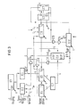
- Fig. 3 ein Blockschaltbild des relevanten Teiles einer Synchronisieranordnung.
- 1 is a schematic representation of a preferred format for the information to be controlled,
- 2 shows a more detailed section from the format of FIG. 1,
- Fig. 3 is a block diagram of the relevant part of a synchronization arrangement.
Das in Fig. 1 dargestellte mögliche Format für eine nach der Erfindung zu übertragende und zu steuernde Information stellt einen Datenblock dar, dem ein Zwischenblock A voransteht und der Teile B, C und D1 bis D16 aufweist. Der Teil B stellt die Synchronisierinformation und der Teil C die zu übertragenden, beispielsweise zeitcodierten Daten dar, die im Hinblick auf die Erfindung keine besondere Bedeutung haben. Die Teile D1 bis D16 schließlich sind Unterblöcke einer beispielsweise digitalen Audioinformation. Einem solchen Format liegt das Format eines Fernsehbildsignals zugrunde. Die Zeit jedes Teils des Blockes entspricht dabei einer Zeileninformation. Ein vollständiger Block hat hierbei eine Periode von 20 ms und enthält beispielsweise 313 Zeilen. Das eine Dauer von 20 Zeilen aufweisende Taktsignal kann im Zwischenblock enthalten sein und stellt in diesem Falle eine Zeitperiode dar, in der das Aufnahmegerät von einer Eingangssignalquelle auf eine andere für Zwecke des »Editing« umgeschaltet werden kann. Darüber hinaus ermöglicht dieses Format die Verwendung eines Aufnahmegerätes mit Wendelabtastung, bei dem ein geringer Teil des Zwischenblockabschnitts üblicherweise im Intervall zwischen zwei aufeinanderfolgenden Abtastungen verloren geht. Der Decodierer, der für die Rückgewinnung der Information benötigt wird, kann einen Taktoszillator aufweisen, dessen Phase vom Taktsignal bestimmt wird, das durch die aufeinanderfolgenden Zeitschlitze zwischen den Blöcken verfügbar ist.The possible format shown in FIG. 1 for information to be transmitted and controlled according to the invention represents a data block which is preceded by an intermediate block A and which has parts B, C and D1 to D16. Part B represents the synchronization information and part C the data to be transmitted, for example time-coded data, which have no particular significance with regard to the invention. Finally, parts D1 to D16 are sub-blocks of one for example digital audio information. Such a format is based on the format of a television picture signal. The time of each part of the block corresponds to line information. A complete block has a period of 20 ms and contains, for example, 313 lines. The clock signal, which has a duration of 20 lines, can be contained in the intermediate block and in this case represents a time period in which the recording device can be switched from one input signal source to another for the purposes of “editing”. In addition, this format enables the use of a recording device with helical scanning, in which a small part of the intermediate block section is usually lost in the interval between two successive scans. The decoder needed to recover the information may have a clock oscillator, the phase of which is determined by the clock signal available through the successive time slots between the blocks.
Die Synchronisierinformation B belegt die ersten drei Zeilen des Datenblocks aus den Teilen B, C und D1 bis D16 und macht, wie noch ausgeführt werden wird, von der Festlegung der Phase eines Hilfsgenerators Gebrauch, der Synchronisiersignale für die Steuerung der zu decodierenden Information des Restdatenblockes erzeugt.The synchronization information B occupies the first three lines of the data block from parts B, C and D1 to D16 and, as will be explained below, makes use of the determination of the phase of an auxiliary generator which generates synchronization signals for controlling the information of the remaining data block to be decoded .
Ein geeignetes Format für die Synchronisierinformation zeigt Fig. 2. Eine Reihe von in diesem Beispiel jeweils aus acht Bits bestehenden Worten werden am Anfang der ersten Zeile, in der Mitte der zweiten Zeile und am Ende der dritten Zeile angeordnet. Bei diesem Beispiel gibt es somit vierundzwanzig codierte Synchronisierworte S1 bis S24. Der Rest jeder Zeile ist mit einem Taktsignal c belegt, das aus der kontinuierlichen Reihenfolge von Bits 101010 ... besteht. Ein solches Taktsignal c belegt auch jeden 8-Bit-Abschnitt zwischen den Synchronisierworten S1 bis S24. Jedes Synchronisierwort ist eindeutig und vorzugsweise so gewählt, daß wenn es nach links oder rechts mit anderen benachbarten Bits verschoben wird, kein anderes von irgendeinem der übrigen Synchronisierworte der Serie bilden kann. Daraus folgt, daß die Anzahl der möglichen 8-Bit-Worte begrenzt ist und es darüber hinaus bei diesem besonderen Informationsformat nicht möglich ist, alle drei Zeilen mit 8-Bit-Worten anzufüllen, die sich mit 8-Bit-Abschnitten für Taktsignale abwechseln.A suitable format for the synchronization information is shown in FIG. 2. A series of words, each consisting of eight bits in this example, are arranged at the beginning of the first line, in the middle of the second line and at the end of the third line. In this example, there are therefore twenty-four coded synchronization words S1 to S24. The rest of each line is occupied by a clock signal c, which consists of the continuous sequence of bits 101010 ... Such a clock signal c also occupies every 8-bit section between the synchronization words S1 to S24. Each synchronization word is unique and is preferably chosen such that when it is shifted left or right with other adjacent bits, it cannot form another of any of the other synchronization words in the series. It follows that the number of possible 8-bit words is limited and, furthermore, it is not possible with this particular information format to fill all three lines with 8-bit words which alternate with 8-bit sections for clock signals.
Jedes Synchronisierwort ist bei diesem Format indirekt hinsichtlich des Abstandes zu einem synchronisierenden Bezugspunkt festgelegt, der dabei eine durch das Bitmuster ausgedrückten Zahl ist. Der synchronisierende Bezugspunkt ist dabei durch das Ende der dritten Zeile vorgegeben. Der Zusammenhang jedes Synchronisierwortes mit dem jeweiligen Abstand ist mittels eines anderen jeweiligen Wortes gegeben, das vom auch eine Adresse darstellenden Synchronisierwort aus einem ROM ausgelesen werden kann.In this format, each synchronization word is indirectly defined with regard to the distance to a synchronizing reference point, which is a number expressed by the bit pattern. The synchronizing reference point is specified by the end of the third line. The connection of each synchronization word with the respective distance is given by means of another respective word which can be read from a ROM by the synchronization word which also represents an address.
Der Synchronisiervorgang soll nun anhand der in Fig. 3 dargestellten Schaltung noch näher beschrieben werden.The synchronization process will now be described in more detail with reference to the circuit shown in FIG. 3.
Die ankommenden Daten werden über den Eingangsanschluß 1 einem getakteten Schieberegister IC1 zugeführt, das diese Daten jeweils in 8-Bit-Worten an zwei ROMs IC2 und IC3 weitergibt. Diese ROMs nehmen die Daten auf und dienen der Erkennung der Synchronisierworte. Wenn ein Synchronisierwort erkannt ist, geben die ROMs die Signale Lo, Li, P und »ABCD« an ihre Ausgänge dann ab, wenn am Eingang S des ROMs IC2 ein Vorbereitungssignal SYNC ansteht. Die Signale Lo und L1 werden dem Endabschnitt eines getakteten ersten Zählers zugeführt, der aus den Zählerstufen IC4, IC5 und IC6 besteht. Die Signale Lo und Ll legen zusammen mit den Signalen ABCD die Zeit fest, die der erste Zähler zählen muß, bevor er das Ende der dritten Zeile des die Synchronisierinformation aufweisenden Teils B eines Informationsblocks erreicht. Der Impuls P wird jedesmal dann erzeugt, wenn ein Synchronisierwort auftritt. Beim erstmaligen Auftreten eines Synchronisierwortes wird der erste Zähler durch das Wort ABCD gesetzt, der hierbei durch die Gatter IC9 und IC10 vorbereitet wird.The incoming data are fed via the
Der durch die Zählerstufen IC4 und IC5 gegebene Zählerstand des ersten Zählers wird mittels des ROMs IC7 decodiert. Stimmt der Zählerstand genau mit dem Synchronisierwort überein, dessen Decodierung das Wort ABCD ergab, dann gibt das ROM das gleiche Wort ABCD ab, was immer auch dieses Wort sein mag.The counter reading of the first counter given by the counter stages IC4 and IC5 is decoded by means of the ROM IC7. If the counter reading corresponds exactly to the synchronization word, the decoding of which gave the word ABCD, then the ROM outputs the same word ABCD, whatever that word may be.
Der Impuls P bewirkt seinerseits das Setzen des zweiten Zählers IC12 für eine vorgegebene Zahl N, die eine Mindestzahl von Synchronisierworten festlegt, die richtig erkannt sein müssen, wenn das ausgangsseitige Synchronisiersignal erzeugt werden soll.The pulse P in turn causes the second counter IC12 to be set for a predetermined number N, which defines a minimum number of synchronization words which must be correctly recognized if the synchronization signal on the output side is to be generated.
Sobald ein zweites Synchronisierwort festgestellt wird, prüft der Komparator IC8 die Übereinstimmung mit dem betreffenden Ausgangswort ABCD und dem Ausgangssignal des ROMs IC7, das dem Zählerstand des ersten Zählers entspricht. Wenn die Übertragung der Daten einwandfrei synchronisiert ist, hält die Erzeugung der Synchronisierworte mit dem Fortschreiten des ersten Zählers Schritt, so daß zwischen dem Ausgang des ROMs IC7 und dem Ausgang des ROMs IC3 stets Übereinstimmung vorhanden ist.As soon as a second synchronization word is determined, the comparator IC8 checks the correspondence with the relevant output word ABCD and the output signal of the ROM IC7, which corresponds to the counter reading of the first counter. If the transmission of the data is perfectly synchronized, the generation of the synchronization words keeps pace with the progress of the first counter, so that there is always a match between the output of the ROM IC7 and the output of the ROM IC3.
Stellt der Komparator diese Übereinstimmung fest, dann wird der Impuls, welcher am Ausgang des Gatters IC10 erscheinen würde, um den ersten Zähler mit dem erneut erkannten Synchronisierwort zu setzen, unterdrückt und gleichzeitig der zweite Zähler IC12 um »1« erhöht. Eine entsprechende Prüfung wird für jedes ankommende Synchronisierwort so lange durchgeführt, bis der zweite Zähler IC12 die vorgegebene Anzahl, beispielsweise 15, gezählt hat. Hat der zweite Zähler IC12 diese Zählstellung erreicht, dann erzeugt er ein Vorbereitungssignal für das zweite der beiden hintereinander geschalteten D-Flip-Flops IC15 und IC16.If the comparator determines this correspondence, the pulse which would appear at the output of the gate IC10 in order to set the first counter with the newly recognized synchronization word is suppressed and at the same time the second counter IC12 is increased by "1". A corresponding check is carried out for each incoming synchronization word until the second counter IC12 has counted the predetermined number, for example 15. If the second counter IC12 has reached this count position, then it generates a preparation signal for the second of the two D-flip-flops IC15 and IC16 connected in series.
Wird jedoch die Übereinstimmung nicht festgestellt, dann wird der Zählerstand der Zählerstufe IC5 des ersten Zählers dahingehend geändert, daß er mit dem Ausgang des ROMs IC3 übereinstimmt und zwar durch Setzen dieser Zählerstufe mit dem Ausgangssignal dieses Speichers.However, if the match is not found, the counter reading of the counter stage IC5 of the first counter is changed so that it matches the output of the ROM IC3 by setting this counter stage with the output signal of this memory.
Der erste Zähler ist so ausgelegt, daß er mit seiner Zählerstufe IC6 die Zählstellung am Ende der dritten Zeile erreicht. In dieser Zählstellung veranlaßt die Zählerstufe IC6 die Rückstellung des D-Flip-Flops IC16 über das D-Flip-Flop IC15. Die Anstiegsflanke des Befehlsausgangs des D-Flip-Flops IC16 bildet dann das gewünschte Synchronisiersignal.The first counter is designed so that it reaches the counting position at the end of the third line with its counter stage IC6. In this count position, the counter stage IC6 causes the D flip-flop IC16 to be reset via the D flip-flop IC15. The rising edge of the command output of the D flip-flop IC16 then forms the desired synchronization signal.
Wenn der zweite Zähler IC12 die Mindestanzahl zu erkennender Synchronisierworte gezählt hat, schaltet der erwähnte Hilfsgenerator das Vorbereitungssignal am Vorbereitungseingang des ROMs IC2 ab und beendet dadurch die Erzeugung des Impulses P. Damit ist dieses ROM für den Rest des ankommenden Datenblocks gesperrt. Darüber hinaus kann das Vorbereitungssignal dazu benutzt werden, das Erkennen eines Synchronisierwortes nur in einem Zeitbereich zu gestatten, in dem ein Synchronisierwort zu erwarten ist. Eine solche Art der Vorbereitung trägt den Zeitänderungen Rechnung, die durch »Editing« und mechanische Störungen des Bandtransportes verursacht werden.When the second counter IC12 has counted the minimum number of synchronization words to be recognized, the auxiliary generator mentioned switches off the preparation signal at the preparation input of the ROM IC2 and thereby ends the generation of the pulse P. This ROM is thus blocked for the rest of the incoming data block. In addition, the preparation signal can be used to permit the recognition of a synchronization word only in a time range in which a synchronization word is to be expected. This type of preparation takes into account the changes in time caused by "editing" and mechanical disruptions in the tape transport.
Claims (5)
Priority Applications (1)
| Application Number | Priority Date | Filing Date | Title |
|---|---|---|---|
| AT80108136T ATE8942T1 (en) | 1980-01-09 | 1980-12-22 | DIGITAL TRANSMISSION SYSTEM. |
Applications Claiming Priority (2)
| Application Number | Priority Date | Filing Date | Title |
|---|---|---|---|
| GB8000710 | 1980-01-09 | ||
| GB8000710A GB2068687A (en) | 1980-01-09 | 1980-01-09 | Digital synchronising system |
Publications (3)
| Publication Number | Publication Date |
|---|---|
| EP0032232A2 EP0032232A2 (en) | 1981-07-22 |
| EP0032232A3 EP0032232A3 (en) | 1981-12-02 |
| EP0032232B1 true EP0032232B1 (en) | 1984-08-08 |
Family
ID=10510540
Family Applications (1)
| Application Number | Title | Priority Date | Filing Date |
|---|---|---|---|
| EP80108136A Expired EP0032232B1 (en) | 1980-01-09 | 1980-12-22 | Digital transmission system |
Country Status (7)
| Country | Link |
|---|---|
| US (1) | US4361898A (en) |
| EP (1) | EP0032232B1 (en) |
| JP (1) | JPS56149138A (en) |
| AT (1) | ATE8942T1 (en) |
| CA (1) | CA1179750A (en) |
| DE (1) | DE3068918D1 (en) |
| GB (1) | GB2068687A (en) |
Cited By (1)
| Publication number | Priority date | Publication date | Assignee | Title |
|---|---|---|---|---|
| DE3642636A1 (en) * | 1986-12-13 | 1988-06-23 | Bosch Gmbh Robert | METHOD FOR DETECTING AND SUBSTITUTING SYNCHRONOUS WORDS IN PCM DATA AND CIRCUIT ARRANGEMENT THEREFOR |
Families Citing this family (15)
| Publication number | Priority date | Publication date | Assignee | Title |
|---|---|---|---|---|
| US4425645A (en) | 1981-10-15 | 1984-01-10 | Sri International | Digital data transmission with parity bit word lock-on |
| US4412329A (en) * | 1981-10-15 | 1983-10-25 | Sri International | Parity bit lock-on method and apparatus |
| DE3151251A1 (en) * | 1981-12-24 | 1983-07-07 | Robert Bosch Gmbh, 7000 Stuttgart | METHOD AND CIRCUIT FOR THE PLAYBACK OF DIGITALLY CODED SIGNALS |
| US4525754A (en) * | 1983-04-06 | 1985-06-25 | Ampex Corporation | System and method for synchronization of rotary head magnetic recording/reproducing devices |
| US4660099A (en) * | 1983-05-12 | 1987-04-21 | Victor Company Of Japan, Ltd. | Rotary recording medium having track turns recorded with digital signal and track turns recorded with analog signal |
| GB2156189B (en) * | 1984-03-15 | 1988-01-06 | Gen Electric | Digital word synchronizing arrangements |
| US4763339A (en) * | 1984-03-15 | 1988-08-09 | General Electric Company | Digital word synchronizing arrangement |
| GB2159020B (en) * | 1984-05-16 | 1987-11-18 | Sony Corp | Methods of and apparatus for use in decoding digital data |
| US4777542A (en) * | 1985-04-26 | 1988-10-11 | Mitsubishi Denki Kabushiki Kaisha | Data recording method |
| JPH0640419B2 (en) * | 1985-05-28 | 1994-05-25 | ソニー株式会社 | Sync signal detection circuit |
| DE3533962A1 (en) * | 1985-09-24 | 1987-03-26 | Thomson Brandt Gmbh | METHOD FOR TRANSMITTING A DIGITAL SIGNAL |
| GB2187366B (en) * | 1986-02-27 | 1989-11-08 | Sony Corp | Synchronizing signal decoding |
| DE3639886A1 (en) * | 1986-11-21 | 1988-06-01 | Thomson Brandt Gmbh | CIRCUIT FOR PROCESSING DIGITAL SIGNALS |
| US5321750A (en) * | 1989-02-07 | 1994-06-14 | Market Data Corporation | Restricted information distribution system apparatus and methods |
| FR2709899B1 (en) * | 1993-09-07 | 1995-11-10 | Sagem | Method for detecting a loss of synchronization in a digital communication network and terminal for implementing the method. |
Family Cites Families (8)
| Publication number | Priority date | Publication date | Assignee | Title |
|---|---|---|---|---|
| BE626488A (en) * | 1961-12-26 | |||
| DE1449786B2 (en) * | 1961-12-26 | 1977-07-07 | International Business Machines Corp, Armonk, N.Y. (V.St.A.) | IMPROVED DEVICE FOR RECORDING AND FILLING DATA BLOCKS IN DATA TRACKS OF A SURFACE MEMORY |
| GB1312504A (en) * | 1970-05-20 | 1973-04-04 | Ibm | Control unit for serial data storage apparatus |
| IT1006135B (en) * | 1973-12-27 | 1976-09-30 | Sits Soc It Telecom Siemens | CIRCUIT ARRANGEMENTS FOR CORRECTION OF THE SLIDING ERROR IN DATA TRANSMISSION SYSTEMS USING CYCLIC CODES |
| GB1532444A (en) * | 1975-03-26 | 1978-11-15 | Micro Consultants Ltd | Synchronising data for digital storage systems |
| DE2627618C2 (en) * | 1975-06-23 | 1983-12-01 | International Business Machines Corp., 10504 Armonk, N.Y. | Method for transferring data between magnetic disk memories with different track capacities and different track formats |
| US4008488A (en) * | 1975-08-25 | 1977-02-15 | Braemar Computer Devices, Inc. | Magnetic recording data decoding system |
| US4271520A (en) * | 1979-06-25 | 1981-06-02 | Motorola, Inc. | Synchronizing technique for an error correcting digital transmission system |
-
1980
- 1980-01-09 GB GB8000710A patent/GB2068687A/en not_active Withdrawn
- 1980-12-22 DE DE8080108136T patent/DE3068918D1/en not_active Expired
- 1980-12-22 EP EP80108136A patent/EP0032232B1/en not_active Expired
- 1980-12-22 AT AT80108136T patent/ATE8942T1/en not_active IP Right Cessation
-
1981
- 1981-01-06 CA CA000367955A patent/CA1179750A/en not_active Expired
- 1981-01-07 US US06/223,164 patent/US4361898A/en not_active Expired - Fee Related
- 1981-01-07 JP JP54381A patent/JPS56149138A/en active Pending
Cited By (1)
| Publication number | Priority date | Publication date | Assignee | Title |
|---|---|---|---|---|
| DE3642636A1 (en) * | 1986-12-13 | 1988-06-23 | Bosch Gmbh Robert | METHOD FOR DETECTING AND SUBSTITUTING SYNCHRONOUS WORDS IN PCM DATA AND CIRCUIT ARRANGEMENT THEREFOR |
Also Published As
| Publication number | Publication date |
|---|---|
| EP0032232A3 (en) | 1981-12-02 |
| GB2068687A (en) | 1981-08-12 |
| JPS56149138A (en) | 1981-11-18 |
| DE3068918D1 (en) | 1984-09-13 |
| CA1179750A (en) | 1984-12-18 |
| ATE8942T1 (en) | 1984-08-15 |
| US4361898A (en) | 1982-11-30 |
| EP0032232A2 (en) | 1981-07-22 |
Similar Documents
| Publication | Publication Date | Title |
|---|---|---|
| EP0032232B1 (en) | Digital transmission system | |
| AT393429B (en) | MEMORY CIRCUIT FOR SAVING A DIGITAL SIGNAL | |
| DE3102967C2 (en) | ||
| DE3131413C2 (en) | ||
| DE3102996C2 (en) | Method and arrangement for storing and / or transmitting a digital color television information signal | |
| DE2734339C2 (en) | ||
| DE3131069C2 (en) | ||
| DE2460979A1 (en) | METHOD AND CIRCUIT ARRANGEMENT FOR COMPENSATION OF PULSE SHIFTS IN MAGNETIC SIGNAL RECORDING | |
| EP0043151A1 (en) | Device for the treatment of serial information provided with synchronization words | |
| DE2844216C2 (en) | Generation of synchronization bit sequence patterns for code with a limited run length | |
| DE3245439C2 (en) | Time base control device for an information reproducing apparatus | |
| DE2745071C2 (en) | Arrangement for reproducing a composite color image signal | |
| DE3236311C2 (en) | ||
| DE2841728A1 (en) | METHOD AND CIRCUIT FOR THE PLAYBACK OF A VIDEO SIGNAL STORED ON MAGNETIC TAPE WITH VARIABLE SPEED | |
| DE3222658A1 (en) | METHOD AND DEVICE FOR SUPPRESSING ERRORATE DATA | |
| EP0717407B1 (en) | Vibration-resistant reproducing apparatus with improved synchronisation | |
| DE3138310C2 (en) | Circuit arrangement for controlling the horizontal sync signals for a PCM signal playback device | |
| DE2924695C2 (en) | ||
| DE2630197A1 (en) | DATA RECOVERY SYSTEM | |
| DE3431777C2 (en) | ||
| DE2748233C2 (en) | Method and circuit arrangement for inserting an address signal into a video signal | |
| DE3131062C2 (en) | ||
| DE3241950C2 (en) | ||
| DE3724572A1 (en) | SIGNAL READING CIRCUIT IN MAGNETIC RECORDING DEVICE | |
| DE2016447A1 (en) | Circuit for multi-track recording and reproduction of binary information with high bit density |
Legal Events
| Date | Code | Title | Description |
|---|---|---|---|
| PUAI | Public reference made under article 153(3) epc to a published international application that has entered the european phase |
Free format text: ORIGINAL CODE: 0009012 |
|
| AK | Designated contracting states |
Designated state(s): AT BE CH DE FR IT LU NL SE |
|
| PUAL | Search report despatched |
Free format text: ORIGINAL CODE: 0009013 |
|
| AK | Designated contracting states |
Designated state(s): AT BE CH DE FR IT LU NL SE |
|
| 17P | Request for examination filed |
Effective date: 19811030 |
|
| ITF | It: translation for a ep patent filed |
Owner name: STUDIO JAUMANN |
|
| GRAA | (expected) grant |
Free format text: ORIGINAL CODE: 0009210 |
|
| AK | Designated contracting states |
Designated state(s): AT BE CH DE FR IT LI LU NL SE |
|
| REF | Corresponds to: |
Ref document number: 8942 Country of ref document: AT Date of ref document: 19840815 Kind code of ref document: T |
|
| REF | Corresponds to: |
Ref document number: 3068918 Country of ref document: DE Date of ref document: 19840913 |
|
| ET | Fr: translation filed | ||
| PG25 | Lapsed in a contracting state [announced via postgrant information from national office to epo] |
Ref country code: LU Free format text: LAPSE BECAUSE OF NON-PAYMENT OF DUE FEES Effective date: 19841231 |
|
| PLBE | No opposition filed within time limit |
Free format text: ORIGINAL CODE: 0009261 |
|
| STAA | Information on the status of an ep patent application or granted ep patent |
Free format text: STATUS: NO OPPOSITION FILED WITHIN TIME LIMIT |
|
| 26N | No opposition filed | ||
| PGFP | Annual fee paid to national office [announced via postgrant information from national office to epo] |
Ref country code: LU Payment date: 19891122 Year of fee payment: 10 |
|
| PGFP | Annual fee paid to national office [announced via postgrant information from national office to epo] |
Ref country code: FR Payment date: 19891219 Year of fee payment: 10 |
|
| PGFP | Annual fee paid to national office [announced via postgrant information from national office to epo] |
Ref country code: BE Payment date: 19891220 Year of fee payment: 10 |
|
| PGFP | Annual fee paid to national office [announced via postgrant information from national office to epo] |
Ref country code: AT Payment date: 19891222 Year of fee payment: 10 |
|
| PGFP | Annual fee paid to national office [announced via postgrant information from national office to epo] |
Ref country code: SE Payment date: 19891228 Year of fee payment: 10 |
|
| ITTA | It: last paid annual fee | ||
| PGFP | Annual fee paid to national office [announced via postgrant information from national office to epo] |
Ref country code: NL Payment date: 19891231 Year of fee payment: 10 |
|
| PGFP | Annual fee paid to national office [announced via postgrant information from national office to epo] |
Ref country code: DE Payment date: 19900221 Year of fee payment: 10 |
|
| PGFP | Annual fee paid to national office [announced via postgrant information from national office to epo] |
Ref country code: CH Payment date: 19900321 Year of fee payment: 10 |
|
| PG25 | Lapsed in a contracting state [announced via postgrant information from national office to epo] |
Ref country code: AT Effective date: 19901222 |
|
| PG25 | Lapsed in a contracting state [announced via postgrant information from national office to epo] |
Ref country code: SE Effective date: 19901223 |
|
| PG25 | Lapsed in a contracting state [announced via postgrant information from national office to epo] |
Ref country code: LI Effective date: 19901231 Ref country code: CH Effective date: 19901231 Ref country code: BE Effective date: 19901231 |
|
| BERE | Be: lapsed |
Owner name: POLYGRAM G.M.B.H. Effective date: 19901231 |
|
| PG25 | Lapsed in a contracting state [announced via postgrant information from national office to epo] |
Ref country code: NL Effective date: 19910701 |
|
| NLV4 | Nl: lapsed or anulled due to non-payment of the annual fee | ||
| PG25 | Lapsed in a contracting state [announced via postgrant information from national office to epo] |
Ref country code: FR Effective date: 19910830 |
|
| REG | Reference to a national code |
Ref country code: CH Ref legal event code: PL |
|
| PG25 | Lapsed in a contracting state [announced via postgrant information from national office to epo] |
Ref country code: DE Effective date: 19910903 |
|
| REG | Reference to a national code |
Ref country code: FR Ref legal event code: ST |
|
| EUG | Se: european patent has lapsed |
Ref document number: 80108136.5 Effective date: 19910910 |