EP0029748B1 - Optical measuring system - Google Patents
Optical measuring system Download PDFInfo
- Publication number
- EP0029748B1 EP0029748B1 EP80304249A EP80304249A EP0029748B1 EP 0029748 B1 EP0029748 B1 EP 0029748B1 EP 80304249 A EP80304249 A EP 80304249A EP 80304249 A EP80304249 A EP 80304249A EP 0029748 B1 EP0029748 B1 EP 0029748B1
- Authority
- EP
- European Patent Office
- Prior art keywords
- strip
- signals
- sensors
- edge
- width
- Prior art date
- Legal status (The legal status is an assumption and is not a legal conclusion. Google has not performed a legal analysis and makes no representation as to the accuracy of the status listed.)
- Expired
Links
Images


Classifications
-
- G—PHYSICS
- G01—MEASURING; TESTING
- G01B—MEASURING LENGTH, THICKNESS OR SIMILAR LINEAR DIMENSIONS; MEASURING ANGLES; MEASURING AREAS; MEASURING IRREGULARITIES OF SURFACES OR CONTOURS
- G01B11/00—Measuring arrangements characterised by the use of optical techniques
- G01B11/02—Measuring arrangements characterised by the use of optical techniques for measuring length, width or thickness
- G01B11/04—Measuring arrangements characterised by the use of optical techniques for measuring length, width or thickness specially adapted for measuring length or width of objects while moving
- G01B11/046—Measuring arrangements characterised by the use of optical techniques for measuring length, width or thickness specially adapted for measuring length or width of objects while moving for measuring width
-
- G—PHYSICS
- G01—MEASURING; TESTING
- G01B—MEASURING LENGTH, THICKNESS OR SIMILAR LINEAR DIMENSIONS; MEASURING ANGLES; MEASURING AREAS; MEASURING IRREGULARITIES OF SURFACES OR CONTOURS
- G01B11/00—Measuring arrangements characterised by the use of optical techniques
- G01B11/02—Measuring arrangements characterised by the use of optical techniques for measuring length, width or thickness
- G01B11/024—Measuring arrangements characterised by the use of optical techniques for measuring length, width or thickness by means of diode-array scanning
-
- G—PHYSICS
- G01—MEASURING; TESTING
- G01B—MEASURING LENGTH, THICKNESS OR SIMILAR LINEAR DIMENSIONS; MEASURING ANGLES; MEASURING AREAS; MEASURING IRREGULARITIES OF SURFACES OR CONTOURS
- G01B11/00—Measuring arrangements characterised by the use of optical techniques
- G01B11/02—Measuring arrangements characterised by the use of optical techniques for measuring length, width or thickness
- G01B11/06—Measuring arrangements characterised by the use of optical techniques for measuring length, width or thickness for measuring thickness ; e.g. of sheet material
- G01B11/0691—Measuring arrangements characterised by the use of optical techniques for measuring length, width or thickness for measuring thickness ; e.g. of sheet material of objects while moving
Definitions
- the present invention relates to electro-optical distance measurement.
- two cameras are arranged each to view one edge of the strip and the separation of the cameras is controlled by a servo-mechanism in such a manner as to centre the image of the two edges on the respective cameras.
- the separation of the cameras is then an indication of the width of the strip.
- this method of measurement is not sufficiently accurate since the camera supports will expand with temperature and impair the measurement accuracy.
- GB-A-2 021 762 Another and superior system for the measurement of strip being rolled is described in GB-A-2 021 762.
- This system involves the positioning of two cameras vertically one above the other and both simultaneously viewing the two edges of the strip being rolled.
- the spacing of the imaging system is fixed and is not critical and the system can operate more rapidly and more accurately than the previously described prior art systems.
- US-A-4,067,652 relates to apparatus for measuring the width of rolled and in common with the earlier mentioned proposals suggests the viewing of each edge by a single camera.
- the measuring system therefore does not take into account the lifting of the strip off the bed of the mill and only measures the size of the silhouette of the strip in the plane of the bed.
- the assumption that the stock remains on the bed while being rolled does not hold true and such lifting alone is a substantial cause of inaccuracy.
- the present invention seeks to permit the width of a strip being rolled to be measured with accuracy even when the strip is capable of lifting off the bed of the mill.
- a method of measuring the width of a strip being rolled in a mill, the strip being liable to lift partially or wholly off the bed of the mill comprises using a pair of radiation responsive sensors which each comprise an array of discrete sensing elements and which are arranged above the bed and spaced apart by a known distance, to provide first and second scanning waveform signals, and analysing said scanning waveform signals to derive edge location signals indicative of the points on said scanning wave forms representing the edges of said strip; characterised in that the fields of view of said sensors overlap and the sensors are arranged each to scan the whole width of said strip including the edges, the bearing of each edge relative to each of the sensors is determined from the edge location signals, and the spatial position of each edge relative to the sensors is computed from the said bearings and the known distance between the sensors.
- the present invention proposes stereoscopic viewing enabling the system to take into account the height of the edge being measured above the rolling mill bed as well as its position along the bed.
- the edge location signals are compared with scanning signals stored in a memory, said stored signals having been stored during a calibration phase during which a grid of known dimensions is placed in a number of predetermined positions, so as to obtain spatial position signals representing the positions in three dimensions of the edges of said strip; and said spatial position signals are used to evaluate the width of the strip.
- edges of the strip being rolled are imaged onto the sensors by means of an optical system of lenses and in order to avoid distortions caused by the optical system it is necessarily to resort to complex optical systems which are costly to manufacture.
- the output signals of the sensors instead of attempting to eliminate errors caused by the optical system, the existence of such errors is recognised and their effect reduced by resorting to calibration.
- the output signals of the sensors it is preferable for the output signals of the sensors to be modified in accordance with a predetermined correction function so as to compensate for inaccuracy caused by the optical systems associated with the sensors, the correction function being determined by the use of a calibration grid which may, if desired, be the same calibration grid as used to store within the memory a matrix of signal pairs representative of the positions of known spatial points relative to the two sensors.
- the system described in Figure 1 is intended to measure the width D and the thickness T of a strip 14 being rolled.
- the optical measurement system includes a first charge coupled device 10 mounted with its focussing system 11 a distance H1 above the plane on which the object 14 rests and a second charge-coupled device 12 mounted with its imaging system 13 a distance H2 above the plane on which the object 14 rests.
- the purpose of the equipment is to measure the width D of the strip 14 and its thickness T. This can be carried out in a known way from the measurements made by the charge-coupled devices 10 and 12.
- the strip 14 is a light emitter or a light reflector, its image can be sensed directly by the charge-coupled devices 10 and 12, but alternatively a light source may be positioned beneath the strip 14 to measure the dimensions of the shadow. Knowing the distances H1 and H2, the sizes of the images on the charge-coupled devices and the magnifications of the imaging systems the dimensions D and T can be computed in a known way.
- the distance H1 may need in some cases to be as much as two metres and this has been found to be inconvenient in certain applications.
- the measuring system employed in the embodiment of Figure 1 assumes that the strip 14 being rolled is resting upon the bed of the rolling mill and this in practice may not be the case, it being common for one edge of the strip to lift off.
- the system in Figure 2 shown very schematically, disposes the two cameras 10' and 12' at a known height H above the bed of the rolling mill and at a known distance W apart. Each of the cameras is capable of seeing both edges of the strip 14 simultaneously.
- the method of computation in this embodiment differs from that previously described.
- the location in space of each of the edges 14a and 14b is calculated. This is a simple problem analogous to that solved in any navigation system wherein the location of a point is determined by taking bearings from two known points.
- Each of the cameras 10' and 12' provides a bearing and the point of intersection is a unique point in space which can readily be calculated.
- the distance the points 14a and 14b is determined within conventional analytical geometry and it is then possible to complete the co-ordinates of the edges 14a and 14b if the strip is bent back to assume a horizontal position resting on the bed.
- the dimensions of the image produced by lines having a predetermined distance apart are stored in a memory and the contents of the memory are read during operation in order to compensate for inaccuracies in the known system.
- Such a method of compensation can readily be performed by digital microprocessor but this feature is not limited to such construction and it is alternatively possible to feed the output of each charge-coupled device to a function generator having a function predetermined during the calibration procedure to correct the inaccuracies resulting from the measurement system.
- the correction function may simply involve linear interpolation between two points measured during calibration but alternatively the function may be more complicated employing functions of higher orders to form a curve defining a best fit with the points measured during calibration. In the latter case, an analogue computation technique is involved which is believed evident to a person skilled in the art.
- the calibration of the lenses should be performed by placing the calibration grid in more than one horizontal position during the calibration process in order to correct for aberrations in all the different planes of measurement.
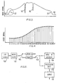
- Figure 3 shows the profile produced on a video camera array when viewing a sheet of rolled steel.
- the minimum values 101 on the left and right of the graph indicate the background radiation.
- the video signal is generally in the form of a half sinusoid with the maximum rate of change corresponding to the edge.
- the maximum value of the half sinusoidal does not correspond to the maximum radiation since the edge of a rolled strip tends to be cooler than the centre, thus there continues a gradient towards the centre of the strip.
- the deep spikes 141 and 161 shown are effects of local cooling which can be caused by water droplets and the general profile will itself be affected by the cooling of the press roller.
- the area of importance for the present application is the part which is circled, that is to say the edge, since it is necessary to detect this edge in order to be able to measure the width of the rolled strip accurately.
- Figure 4 shows the edge drawn to a much enlarged scale showing the idealised video signal from a charge coupled device viewing the edge. Because the video signal is sampled at spaced intervals, by such an array, the maximum rate of change of the video signal cannot be measured directly to an accuracy in excess of one interelement spacing. Further processing cannot however readily be performed in real time because of the large number of elements in a charge coupled device and therefore it is proposed initially that an area of interest be identified and selected from the whole of the video signal for the purpose of analysis. In the case of the profile in Figure 3, this can be achieved by measuring the video signal intensity at the top of the half sinusoid and fixing a threshold level equal to say, half this value as indicative of the likely position at an edge. A memory now stores the video signals from the elements of the array immediately adjacent the crossing of this threshold value and stores only such values for further processing. By reducing the number of elements to be analysed in this way, it is possible to perform the analysis in real time.
- the two elements at which the rate of change is a maximum are first identified. This could, for example, be the elements numbered 13 and 14 in Figure 4. Subsequently, the two elements at which the rate of change drops to a quarter of this maximum value are detected by analysing the video signals from the elements on each side of the maximum rate of change. The average of these locations provides a more accurate assessment of the true position of the point of maximum rate of change and therefore the edge of the strip.
- various fractions of the maximum rate of change have been tried, that is to say a quarter, a third, a half, and in each case the averages were in agreement to an accuracy of one tenth of the interelement spacing. The actual fraction adopted is therefore not critical but approximately a quarter has been found to be the most expedient.
- the signal shown in Figure 4 is a signal which has been cleaned from various interfering noises.
- each charge coupled device has a characteristic random noise associated with it, often termed the signature, as each signature is peculiar to a given device.
- This signal must first be removed, for example by viewing a neutral background, measuring the noise signal and subtracting it from any subsequent measurements made during operation.
- a charge coupled device camera 100 is connected to a noise filter 102 which removes the sources of noise mentioned hereinbefore.
- the video signal is applied by an electronic switch 104 alternately to two random access memories RAM1 and RAM2. While the signal is being written into RAM1 the video signal from the preceding line is read from RAM2 and vice versa.
- An area of interest processing unit 108 is connected alternately to the random access memories RAM1 and RAM2 by means of an electronic switch 106 which operates in synchronism with the switch 104.
- the area of interest circuit 108 determines a threshold which corresponds to likely positions of an edge and enters that information into a main processing unit 110.
- the main processing unit now examines the video signal in the random access memory in the vicinity of each area of interest in accordance with the principle described above to determine the maximum rate of change of the video signal and after further processing provides an output from an output unit 112.
- two cameras 210 and 212 are arranged side by side one another above a calibration grid 214 which is arranged in a position corresponding to that adopted by a rolled strip when the system is in operation. It is desired to combine the individual outputs of the two cameras of the stereo system without resorting to trigonometrical computations in order to determine the accurate positioning in space of the edges of the strip being rolled.
- the calibration grid is placed at an accurately measured position relative to the stereo camera system.
- the video signals derived during this calibration phase are entered into a memory of the processing unit connected to the cameras so as to form a look-up table assigning to each position known in space from the positioning of the calibration grid two co-ordinates corresponding to the positions on the two cameras on which the image of the said point in space is incident.
- the grid After recording the pairs of co-ordinates for all the lines on the calibration grid at first spacing of the grid from the camera, the grid is moved to a new position and a further set of calibration values is determined, this process being continued to form a matrix of points in space for which the co-ordinates (as defined above) are recorded in the memory as a look-up table.
- the processing unit determines the position of an edge during operation by interpolation. Any point falling generally within the matrix of calibration points will fall within a square or rectangle, the corners of which have known co-ordinates. By linear interpolation of the values within that square, involving only simple sums of addition and multiplication which may be done rapidly, it is possible to compute the exact position of the edge when lying at any point falling within the calibration matrix.
Landscapes
- Physics & Mathematics (AREA)
- General Physics & Mathematics (AREA)
- Length Measuring Devices By Optical Means (AREA)
- Image Processing (AREA)
Description
- The present invention relates to electro-optical distance measurement.
- It has already been proposed to measure the length of an object by imaging the object onto, for example, a camera and performing measurements on the image. This method of measurement lends itself particularly to the measurement of the width of a strip being rolled, although it does have numerous other applications.
- In one method of measuring the width of a strip being rolled, two cameras are arranged each to view one edge of the strip and the separation of the cameras is controlled by a servo-mechanism in such a manner as to centre the image of the two edges on the respective cameras. The separation of the cameras is then an indication of the width of the strip. Apart from the slowness of the reaction of the servo-control loop, this method of measurement is not sufficiently accurate since the camera supports will expand with temperature and impair the measurement accuracy.
- Another and superior system for the measurement of strip being rolled is described in GB-A-2 021 762. This system involves the positioning of two cameras vertically one above the other and both simultaneously viewing the two edges of the strip being rolled. In this method the spacing of the imaging system is fixed and is not critical and the system can operate more rapidly and more accurately than the previously described prior art systems.
- However, the system employing two cameras lying vertically one above the other above the edges of the strip to be rolled suffers from the disadvantage that the higher of the two cameras must typically be some six feet above the strip in order to achieve the desired accuracy. Such a clearance has in practice been found to be unacceptable as the system could then interfere with or be damaged by other equipment in the rolling mill.
- US-A-4,067,652 relates to apparatus for measuring the width of rolled and in common with the earlier mentioned proposals suggests the viewing of each edge by a single camera. The measuring system therefore does not take into account the lifting of the strip off the bed of the mill and only measures the size of the silhouette of the strip in the plane of the bed. In practice, the assumption that the stock remains on the bed while being rolled does not hold true and such lifting alone is a substantial cause of inaccuracy.
- The present invention seeks to permit the width of a strip being rolled to be measured with accuracy even when the strip is capable of lifting off the bed of the mill.
- In accordance with the present invention, there is provided a method of measuring the width of a strip being rolled in a mill, the strip being liable to lift partially or wholly off the bed of the mill, which method comprises using a pair of radiation responsive sensors which each comprise an array of discrete sensing elements and which are arranged above the bed and spaced apart by a known distance, to provide first and second scanning waveform signals, and analysing said scanning waveform signals to derive edge location signals indicative of the points on said scanning wave forms representing the edges of said strip; characterised in that the fields of view of said sensors overlap and the sensors are arranged each to scan the whole width of said strip including the edges, the bearing of each edge relative to each of the sensors is determined from the edge location signals, and the spatial position of each edge relative to the sensors is computed from the said bearings and the known distance between the sensors.
- During the course of rolling a strip, it is possible for one or both edges of the strip to lift off the bed of the rolling mill. Such distortions of the strip would result in inaccurate readings if, as proposed in the above mentioned U.S. Patent, only one sensor or camera is used to view each edge. The present invention, by contrast, proposes stereoscopic viewing enabling the system to take into account the height of the edge being measured above the rolling mill bed as well as its position along the bed.
- When monitoring the width of a strip being rolled in a mill, it is necessary to perform all the processing of the data derived from the sensors in real time. It would be possible to compute the locations of the edges by standard trigonometry, but digital computers are not well suited to perform such a task at speed.
- In a preferred embodiment of the invention, the edge location signals are compared with scanning signals stored in a memory, said stored signals having been stored during a calibration phase during which a grid of known dimensions is placed in a number of predetermined positions, so as to obtain spatial position signals representing the positions in three dimensions of the edges of said strip; and said spatial position signals are used to evaluate the width of the strip.
- It should be mentioned that the use of a calibration grid is already known and has been previously proposed in US-A-3 902 811. In the present invention, however, the calibration is carried out not just in one plane but in several planes to create a grid in space of known points.
- The edges of the strip being rolled are imaged onto the sensors by means of an optical system of lenses and in order to avoid distortions caused by the optical system it is necessarily to resort to complex optical systems which are costly to manufacture.
- In a preferred feature of the invention, instead of attempting to eliminate errors caused by the optical system, the existence of such errors is recognised and their effect reduced by resorting to calibration. Thus, it is preferable for the output signals of the sensors to be modified in accordance with a predetermined correction function so as to compensate for inaccuracy caused by the optical systems associated with the sensors, the correction function being determined by the use of a calibration grid which may, if desired, be the same calibration grid as used to store within the memory a matrix of signal pairs representative of the positions of known spatial points relative to the two sensors.
- The invention will now be described further, by way of example, with reference to the accompanying drawings, in which:
- Figure 1 is a schematic representation of a known electro-optical distance measurement system,
- Figure 2 is a similar representation of a second distance measurement system in accordance with the invention,
- Figure 3 is a profile of the radiation emitted by a rolled sheet of steel,
- Figure 4 is a detail of the video signal produced from a video array showing only the part encircled in Figure 3,
- Figure 5 is a block diagram of an arrangement for accurate edge detection, and
- Figure 6 shows two cameras arranged above a calibration grid.
- The system described in Figure 1 is intended to measure the width D and the thickness T of a
strip 14 being rolled. The optical measurement system includes a first charge coupleddevice 10 mounted with its focussing system 11 a distance H1 above the plane on which theobject 14 rests and a second charge-coupleddevice 12 mounted with its imaging system 13 a distance H2 above the plane on which theobject 14 rests. The purpose of the equipment is to measure the width D of thestrip 14 and its thickness T. This can be carried out in a known way from the measurements made by the charge-coupleddevices - If the
strip 14 is a light emitter or a light reflector, its image can be sensed directly by the charge-coupleddevices strip 14 to measure the dimensions of the shadow. Knowing the distances H1 and H2, the sizes of the images on the charge-coupled devices and the magnifications of the imaging systems the dimensions D and T can be computed in a known way. - In the system shown in Figure 1, the distance H1 may need in some cases to be as much as two metres and this has been found to be inconvenient in certain applications. Furthermore, the measuring system employed in the embodiment of Figure 1 assumes that the
strip 14 being rolled is resting upon the bed of the rolling mill and this in practice may not be the case, it being common for one edge of the strip to lift off. - The system in Figure 2, shown very schematically, disposes the two cameras 10' and 12' at a known height H above the bed of the rolling mill and at a known distance W apart. Each of the cameras is capable of seeing both edges of the
strip 14 simultaneously. The method of computation in this embodiment, however, differs from that previously described. In place of assuming that thestrip 14 is resting on the bed, the location in space of each of theedges 14a and 14b is calculated. This is a simple problem analogous to that solved in any navigation system wherein the location of a point is determined by taking bearings from two known points. Each of the cameras 10' and 12' provides a bearing and the point of intersection is a unique point in space which can readily be calculated. - If the
points 14a and 14b are found to lie in a different horizontal plane from one another, the distance thepoints 14a and 14b is determined within conventional analytical geometry and it is then possible to complete the co-ordinates of theedges 14a and 14b if the strip is bent back to assume a horizontal position resting on the bed. - The accuracies of the measurements in any system depend on the quality of the
optical systems - With a view to improving the accuracy of such a system without significantly increasing the cost, it is possible to place a grid in the position of the
strip 14 in order to calibrate the system. - To implement this technique, the dimensions of the image produced by lines having a predetermined distance apart are stored in a memory and the contents of the memory are read during operation in order to compensate for inaccuracies in the known system. Such a method of compensation can readily be performed by digital microprocessor but this feature is not limited to such construction and it is alternatively possible to feed the output of each charge-coupled device to a function generator having a function predetermined during the calibration procedure to correct the inaccuracies resulting from the measurement system. The correction function may simply involve linear interpolation between two points measured during calibration but alternatively the function may be more complicated employing functions of higher orders to form a curve defining a best fit with the points measured during calibration. In the latter case, an analogue computation technique is involved which is believed evident to a person skilled in the art.
- As in the embodiment of Figure 2, readings are not only taken when the
strip 14 is resting on the bed, but also when the edges are raised above it, the calibration of the lenses should be performed by placing the calibration grid in more than one horizontal position during the calibration process in order to correct for aberrations in all the different planes of measurement. - There now follows a description of the edge detection; Figure 3 shows the profile produced on a video camera array when viewing a sheet of rolled steel. The
minimum values 101 on the left and right of the graph indicate the background radiation. At theedges 121 the video signal is generally in the form of a half sinusoid with the maximum rate of change corresponding to the edge. The maximum value of the half sinusoidal does not correspond to the maximum radiation since the edge of a rolled strip tends to be cooler than the centre, thus there continues a gradient towards the centre of the strip. Thedeep spikes - Figure 4 shows the edge drawn to a much enlarged scale showing the idealised video signal from a charge coupled device viewing the edge. Because the video signal is sampled at spaced intervals, by such an array, the maximum rate of change of the video signal cannot be measured directly to an accuracy in excess of one interelement spacing. Further processing cannot however readily be performed in real time because of the large number of elements in a charge coupled device and therefore it is proposed initially that an area of interest be identified and selected from the whole of the video signal for the purpose of analysis. In the case of the profile in Figure 3, this can be achieved by measuring the video signal intensity at the top of the half sinusoid and fixing a threshold level equal to say, half this value as indicative of the likely position at an edge. A memory now stores the video signals from the elements of the array immediately adjacent the crossing of this threshold value and stores only such values for further processing. By reducing the number of elements to be analysed in this way, it is possible to perform the analysis in real time.
- In the profile shown in Figure 3, only three areas will be identified as being of interest, two being the
true edges 121 of the strip and one being thespike 141 caused by a water droplet. Because of the obvious differences in two signals one can readily distinguish the true edges from such spikes. - To enable detection of the point of maximum rate of change, the two elements at which the rate of change is a maximum are first identified. This could, for example, be the elements numbered 13 and 14 in Figure 4. Subsequently, the two elements at which the rate of change drops to a quarter of this maximum value are detected by analysing the video signals from the elements on each side of the maximum rate of change. The average of these locations provides a more accurate assessment of the true position of the point of maximum rate of change and therefore the edge of the strip. By experiment, various fractions of the maximum rate of change have been tried, that is to say a quarter, a third, a half, and in each case the averages were in agreement to an accuracy of one tenth of the interelement spacing. The actual fraction adopted is therefore not critical but approximately a quarter has been found to be the most expedient.
- It should here be mentioned that the signal shown in Figure 4 is a signal which has been cleaned from various interfering noises. For example, each charge coupled device has a characteristic random noise associated with it, often termed the signature, as each signature is peculiar to a given device. This signal must first be removed, for example by viewing a neutral background, measuring the noise signal and subtracting it from any subsequent measurements made during operation.
- It is also inherent in the construction of a charge coupled device that the gain may vary from one element to the next but that alternate elements are matched. Therefore, to avoid the superimposition of a signal having a wavelength related to the interelement spacing, the signals from alternate elements are analysed separately.
- In Figure 5, a charge coupled
device camera 100 is connected to anoise filter 102 which removes the sources of noise mentioned hereinbefore. The video signal is applied by anelectronic switch 104 alternately to two random access memories RAM1 and RAM2. While the signal is being written into RAM1 the video signal from the preceding line is read from RAM2 and vice versa. An area ofinterest processing unit 108 is connected alternately to the random access memories RAM1 and RAM2 by means of anelectronic switch 106 which operates in synchronism with theswitch 104. The area ofinterest circuit 108 determines a threshold which corresponds to likely positions of an edge and enters that information into amain processing unit 110. The main processing unit now examines the video signal in the random access memory in the vicinity of each area of interest in accordance with the principle described above to determine the maximum rate of change of the video signal and after further processing provides an output from anoutput unit 112. - In Figure 6, two
cameras 210 and 212 are arranged side by side one another above acalibration grid 214 which is arranged in a position corresponding to that adopted by a rolled strip when the system is in operation. It is desired to combine the individual outputs of the two cameras of the stereo system without resorting to trigonometrical computations in order to determine the accurate positioning in space of the edges of the strip being rolled. - During the initial setting up of the two camera stereo system, which is connected, as described above to a processing unit serving to determine the accurate positions of the edges of the rolled strip, the calibration grid is placed at an accurately measured position relative to the stereo camera system. The video signals derived during this calibration phase are entered into a memory of the processing unit connected to the cameras so as to form a look-up table assigning to each position known in space from the positioning of the calibration grid two co-ordinates corresponding to the positions on the two cameras on which the image of the said point in space is incident. After recording the pairs of co-ordinates for all the lines on the calibration grid at first spacing of the grid from the camera, the grid is moved to a new position and a further set of calibration values is determined, this process being continued to form a matrix of points in space for which the co-ordinates (as defined above) are recorded in the memory as a look-up table.
- After the calibration of a camera system, which need not be done on site, the processing unit determines the position of an edge during operation by interpolation. Any point falling generally within the matrix of calibration points will fall within a square or rectangle, the corners of which have known co-ordinates. By linear interpolation of the values within that square, involving only simple sums of addition and multiplication which may be done rapidly, it is possible to compute the exact position of the edge when lying at any point falling within the calibration matrix.
- Reference is made to copending European Patent Application No. 83103927.6, Publication No. EP-A-0094522, which contains the same disclosure as the present application but the claims of which are directed a method of locating the edge of a strip.
Claims (8)
Priority Applications (1)
| Application Number | Priority Date | Filing Date | Title |
|---|---|---|---|
| AT80304249T ATE19825T1 (en) | 1979-11-26 | 1980-11-26 | OPTICAL MEASUREMENT SYSTEM. |
Applications Claiming Priority (6)
| Application Number | Priority Date | Filing Date | Title |
|---|---|---|---|
| GB7940810A GB2064102B (en) | 1979-11-26 | 1979-11-26 | Electro-optical dimension measurement |
| GB7940810 | 1979-11-26 | ||
| GB8009285A GB2072333A (en) | 1980-03-19 | 1980-03-19 | Edge Determination in Image Analysis |
| GB8009285 | 1980-03-19 | ||
| GB8010048A GB2072833A (en) | 1980-03-25 | 1980-03-25 | Optical measuring apparatus |
| GB8010048 | 1980-03-25 |
Related Child Applications (2)
| Application Number | Title | Priority Date | Filing Date |
|---|---|---|---|
| EP83103927.6 Division-Into | 1980-11-26 | ||
| EP83103927A Division EP0094522A3 (en) | 1980-03-19 | 1980-11-26 | Edge detection |
Publications (2)
| Publication Number | Publication Date |
|---|---|
| EP0029748A1 EP0029748A1 (en) | 1981-06-03 |
| EP0029748B1 true EP0029748B1 (en) | 1986-05-14 |
Family
ID=27260808
Family Applications (1)
| Application Number | Title | Priority Date | Filing Date |
|---|---|---|---|
| EP80304249A Expired EP0029748B1 (en) | 1979-11-26 | 1980-11-26 | Optical measuring system |
Country Status (4)
| Country | Link |
|---|---|
| US (3) | US4490617A (en) |
| EP (1) | EP0029748B1 (en) |
| CA (1) | CA1103018A (en) |
| DE (1) | DE3071604D1 (en) |
Families Citing this family (60)
| Publication number | Priority date | Publication date | Assignee | Title |
|---|---|---|---|---|
| US4862397A (en) * | 1983-01-03 | 1989-08-29 | Diffracto Ltd. | Remote operation of optical system |
| EP0114914B1 (en) * | 1983-01-29 | 1987-04-22 | M.A.N.-ROLAND Druckmaschinen Aktiengesellschaft | Device for detecting and evaluating colour control strips on a printing sheet |
| US4679941A (en) * | 1983-09-16 | 1987-07-14 | Citizen Watch Co., Ltd. | Micro-dimensional measurement apparatus |
| GB8512727D0 (en) * | 1985-05-20 | 1985-06-26 | Vickers Plc | Optical metrology |
| GB2180640A (en) * | 1985-09-13 | 1987-04-01 | Tesa Metrology Ltd | Optical measurement apparatus |
| FR2595814A1 (en) * | 1986-03-14 | 1987-09-18 | Bertin & Cie | METHOD AND DEVICE FOR MEASURING THE DIAMETER OF A FIBER, IN PARTICULAR AN OPTICAL FIBER |
| GB8612038D0 (en) * | 1986-05-17 | 1986-06-25 | Tole W R | Dimensional measurement of object |
| US4994990A (en) * | 1987-02-03 | 1991-02-19 | Citizen Watch Co., Ltd. | Micro-dimensional measurement apparatus |
| AU597485B2 (en) * | 1987-04-22 | 1990-05-31 | John Lysaght (Australia) Limited | Non-contact determination of the position of a rectilinear feature of an article |
| US5085502A (en) * | 1987-04-30 | 1992-02-04 | Eastman Kodak Company | Method and apparatus for digital morie profilometry calibrated for accurate conversion of phase information into distance measurements in a plurality of directions |
| NL8702738A (en) * | 1987-11-17 | 1989-06-16 | Heineken Technische Beheer Bv | METHOD AND APPARATUS FOR COUNTING OBJECTS OBTAINED ON A TRANSPORTATION TRACK |
| US5539679A (en) * | 1988-05-27 | 1996-07-23 | Honeywell Inc. | Linearization scheme for optical measurement systems |
| DE3820991A1 (en) * | 1988-06-22 | 1989-12-28 | Ali Bindernagel | METHOD AND DEVICE FOR CALIBRATING A CONTACTLESS MEASURING DEVICE |
| US5104216A (en) * | 1988-12-05 | 1992-04-14 | Igm Industriegerate- Und Maschinenfabriksgesellschaft Mbh | Process for determining the position and the geometry of workpiece surfaces |
| US4962538A (en) * | 1989-02-13 | 1990-10-09 | Comar, Inc. | Image analysis counting system |
| WO1991006827A1 (en) * | 1989-10-24 | 1991-05-16 | Australian Wool Testing Authority Ltd. | Image analysis |
| AU619402B2 (en) * | 1989-10-24 | 1992-01-23 | Australian Wool Testing Authority Ltd | Measuring dimensions of out-of-focus images |
| US5162661A (en) * | 1990-02-08 | 1992-11-10 | Pioneer Electronic Corporation | Position detector for maintaining a fixed distance between two objects |
| US5120976A (en) * | 1990-07-25 | 1992-06-09 | The Boeing Company | Strip lay-up verification system with width and centerline skew determination |
| GB9107037D0 (en) * | 1991-04-04 | 1991-05-22 | Tesa Metrology Ltd | Improvements in or relating to electro-optical measurement apparatus |
| FR2675573B1 (en) * | 1991-04-18 | 1993-07-30 | Saint Gobain Isover | METHOD FOR DIMENSIONAL MEASUREMENTS OF MOVING OBJECTS. |
| JP2722287B2 (en) * | 1991-05-15 | 1998-03-04 | ファナック株式会社 | Position detection method in laser sensor |
| US5220177A (en) * | 1991-06-24 | 1993-06-15 | Harris Instrument Corporation | Method and apparatus for edge detection and location |
| US5347135A (en) * | 1991-06-24 | 1994-09-13 | Harris Instrument Corporation | Method and apparatus employing a linear array IR region radiation devices for locating the position of conveyor transported products |
| DE4124034A1 (en) * | 1991-07-19 | 1993-01-21 | Hoesch Stahl Ag | Measuring width of band even when it lifts out of roller path plane - measuring positions of band edges using various camera outputs and known camera separations and positions w.r.t. roller path |
| US5294803A (en) * | 1991-12-30 | 1994-03-15 | Tandberg Data A/S | System and a method for optically detecting an edge of a tape |
| DE4239270A1 (en) * | 1992-11-23 | 1994-05-26 | Siemens Ag | Process for actuator identification in the cross-profile control of a continuously generated material web |
| DE4240094C2 (en) * | 1992-11-28 | 1995-10-26 | Abb Patent Gmbh | System for monitoring a flow of material to be conveyed in a conveyor system with belt conveyor |
| US5345939A (en) * | 1993-11-24 | 1994-09-13 | General Electric Company | Ultrasound imaging system with dynamic window function |
| US5546808A (en) | 1994-09-06 | 1996-08-20 | Harris Instrument Corporation | Apparatus and method for binocular measurement system |
| US5562788A (en) * | 1994-09-20 | 1996-10-08 | The Boeing Company | Composite material laser flaw detection |
| US5867274A (en) | 1997-02-14 | 1999-02-02 | Harris Instrument Corporation | System for the measurement of the cut length of moving articles |
| US5847834A (en) * | 1997-09-11 | 1998-12-08 | Webview, Inc. | Expandable, continuous illumination source for a web inspection assembly and method |
| US6236429B1 (en) | 1998-01-23 | 2001-05-22 | Webview, Inc. | Visualization system and method for a web inspection assembly |
| US6934028B2 (en) * | 2000-01-20 | 2005-08-23 | Webview, Inc. | Certification and verification management system and method for a web inspection apparatus |
| US6856407B2 (en) * | 2000-09-13 | 2005-02-15 | Nextengine, Inc. | Method for depth detection in 3D imaging providing a depth measurement for each unitary group of pixels |
| KR100450839B1 (en) * | 2001-10-19 | 2004-10-01 | 삼성전자주식회사 | Device and method for detecting edge of each face of three dimensional image |
| FI115558B (en) * | 2002-03-27 | 2005-05-31 | Metso Automation Oy | A method for determining the scale of a detection area |
| US7157726B2 (en) * | 2004-01-16 | 2007-01-02 | Fuji Photo Film Co., Ltd. | Method and apparatus for measuring shape of sheet |
| WO2008028246A1 (en) * | 2006-09-07 | 2008-03-13 | Bluescope Steel Limited | Monitoring of profiled sheets |
| EP2106527A2 (en) * | 2007-01-14 | 2009-10-07 | Microsoft International Holdings B.V. | A method, device and system for imaging |
| KR100917470B1 (en) * | 2007-08-08 | 2009-09-14 | 주식회사 포스코 | Apparatus and Method for Measuring the Center of Gravity of Slabs |
| KR100928803B1 (en) * | 2007-11-29 | 2009-11-25 | 주식회사 포스코 | Apparatus and method for detecting joints of steel sheets in continuous hot rolling |
| KR101439546B1 (en) * | 2007-12-27 | 2014-09-30 | 주식회사 포스코 | Apparatus for detecting defects of side surface of slab |
| US7936277B2 (en) * | 2008-09-26 | 2011-05-03 | Spirit Aerosystems, Inc. | Apparatus and method for width detection |
| CN101598846B (en) * | 2009-06-30 | 2013-05-01 | 河南中光学集团有限公司 | Computer terminal display system and display method for zoom lens target ranging |
| WO2011009108A2 (en) * | 2009-07-17 | 2011-01-20 | Universal Robotics, Inc. | System and method for automatic calibration of stereo images |
| US8280172B1 (en) | 2011-03-22 | 2012-10-02 | Mitutoyo Corporation | Edge location measurement correction for coaxial light images |
| US9062964B1 (en) * | 2012-05-07 | 2015-06-23 | Clearwater Paper Corporation | Laser caliper measurement of paper material |
| JP6079072B2 (en) * | 2012-09-12 | 2017-02-15 | Jfeスチール株式会社 | Hot length measuring method and apparatus |
| BR112018009948A8 (en) * | 2015-12-21 | 2019-02-26 | Philip Morris Products Sa | apparatus and method for obtaining data relating to a dimension of an elongated object |
| EP3408610A4 (en) | 2016-01-25 | 2020-01-01 | Topcon Positioning Systems, Inc. | A method and apparatus for single camera optical measurements |
| TWI614480B (en) * | 2016-12-05 | 2018-02-11 | Optical film width line measuring device and measuring method | |
| BR112019017815B1 (en) * | 2017-03-14 | 2023-11-07 | Jfe Steel Corporation | METHOD AND APPARATUS FOR MEASURING THE AMOUNT OF WINNING OF A STRIP DURING TRANSPORTATION OF THE SAME, AND METHOD AND APPARATUS FOR DETECTING ABNORMAL WINNING |
| CN107515012B (en) * | 2017-07-21 | 2020-10-23 | 北京航天计量测试技术研究所 | Single-axis rotating mechanism-based dynamic vision measurement system calibration device and method |
| MX2020007575A (en) * | 2018-01-19 | 2020-09-07 | Atn Hoelzel Gmbh | Method and device for detecting the position of a seal. |
| US20220272207A1 (en) * | 2021-02-24 | 2022-08-25 | General Electric Company | Automated beam scan calibration, alignment, and adjustment |
| CN113513990B (en) * | 2021-09-13 | 2021-12-07 | 广东三姆森科技股份有限公司 | Measuring method and measuring device for internal dimension of 3C product |
| US11988496B1 (en) | 2022-03-22 | 2024-05-21 | Advanced Gauging Technologies, LLC | Strip width measurement with continuous hardware imperfection corrections of sensed edge positions |
| CN116147506B (en) * | 2023-04-23 | 2023-07-18 | 钛玛科(北京)工业科技有限公司 | Dual CCD camera width measurement method and system |
Citations (1)
| Publication number | Priority date | Publication date | Assignee | Title |
|---|---|---|---|---|
| GB2021762A (en) * | 1978-05-17 | 1979-12-05 | British Steel Corp | Improvements in determining the dimensions of workpieces |
Family Cites Families (12)
| Publication number | Priority date | Publication date | Assignee | Title |
|---|---|---|---|---|
| US2659823A (en) * | 1951-09-21 | 1953-11-17 | Jr Carl A Vossberg | Measuring system |
| US3532887A (en) * | 1968-10-02 | 1970-10-06 | Gen Electric | Measuring by means of the infrared emission therefrom the length of a moving hot metal slab |
| FR2031148A5 (en) * | 1969-02-28 | 1970-11-13 | Instr Physique | |
| US3762818A (en) * | 1970-02-11 | 1973-10-02 | Lockheed Aircraft Corp | Contour measurement apparatus |
| US3902811A (en) * | 1973-06-27 | 1975-09-02 | Vsi Corp | Electro-optical scanning system for dimensional gauging of parts |
| US3854822A (en) * | 1973-06-27 | 1974-12-17 | Vsi Corp | Electro-optical scanning system for dimensional gauging of parts |
| US3907439A (en) * | 1973-08-14 | 1975-09-23 | Zygo Corp | Edge-sensing with a scanning laser beam |
| US3941484A (en) * | 1974-10-31 | 1976-03-02 | Bai Corporation | Non-contact dimensional measurement technique |
| DE2516756A1 (en) * | 1975-04-16 | 1976-10-28 | Betr Forsch Inst Angew Forsch | METHOD AND DEVICE FOR DETERMINING A AREA DIMENSION IN ONE PLANE |
| US4033697A (en) * | 1976-05-17 | 1977-07-05 | Reticon Corporation | Automatic exposure control for a luminous object monitor system |
| US4082463A (en) * | 1977-01-06 | 1978-04-04 | Systems Research Laboratories, Inc. | Calibrated optical micrometer |
| JPS5419664A (en) * | 1977-07-15 | 1979-02-14 | Nippon Jidoseigyo Ltd | Device for inspecting fault of pattern |
-
1980
- 1980-11-25 US US06/210,337 patent/US4490617A/en not_active Expired - Lifetime
- 1980-11-26 DE DE8080304249T patent/DE3071604D1/en not_active Expired
- 1980-11-26 EP EP80304249A patent/EP0029748B1/en not_active Expired
- 1980-11-26 CA CA365,545A patent/CA1103018A/en not_active Expired
-
1982
- 1982-04-15 US US06/368,511 patent/US4499383A/en not_active Expired - Fee Related
-
1984
- 1984-05-17 US US06/591,484 patent/US4670659A/en not_active Expired - Fee Related
Patent Citations (1)
| Publication number | Priority date | Publication date | Assignee | Title |
|---|---|---|---|---|
| GB2021762A (en) * | 1978-05-17 | 1979-12-05 | British Steel Corp | Improvements in determining the dimensions of workpieces |
Also Published As
| Publication number | Publication date |
|---|---|
| CA1103018A (en) | 1981-06-16 |
| US4670659A (en) | 1987-06-02 |
| DE3071604D1 (en) | 1986-06-19 |
| EP0029748A1 (en) | 1981-06-03 |
| US4490617A (en) | 1984-12-25 |
| US4499383A (en) | 1985-02-12 |
Similar Documents
| Publication | Publication Date | Title |
|---|---|---|
| EP0029748B1 (en) | Optical measuring system | |
| EP0627069B1 (en) | Method and apparatus for measuring the shape of a surface of an object | |
| US4776692A (en) | Testing light transmitting articles | |
| US4735508A (en) | Method and apparatus for measuring a curvature of a reflective surface | |
| WO2002075350A1 (en) | Method and device for determining an angular position of a reflector | |
| US5432331A (en) | Method and apparatus for detecting focus of moving images with tilted plane detector and time delay means | |
| EP0488392B1 (en) | Distance measuring apparatus | |
| JPH06147863A (en) | Bending angle detector for bending machine | |
| EP0483362B1 (en) | System for measuring length of sheet | |
| EP0094522A2 (en) | Edge detection | |
| JPS61221610A (en) | Method of detecting position of end edge section of tabular or band-shaped measured member, etc. | |
| EP0174961A1 (en) | Optical article dimension measuring system | |
| CA1138189A (en) | Comparative type measuring calibrating and interpolating system | |
| JP2961140B2 (en) | Image processing method | |
| KR940003791B1 (en) | Width measuring device | |
| JPH05296728A (en) | Breadth measurement method for steel plate | |
| JPH08159728A (en) | Shape measuring instrument | |
| JP3037728B2 (en) | Method for detecting amplitude fluctuations in the field of elements having a multivalent amplitude distribution, apparatus suitable for performing the method, and video system including the apparatus | |
| JPH0735515A (en) | Device for measuring diameter of object | |
| AU571673B2 (en) | Optical article measuring system | |
| JPH05172531A (en) | Distance measuring method | |
| KR20030018182A (en) | The Calibration Apparatus and Mathod for Height Extration | |
| JPH07234116A (en) | Warpage rate measuring method for plate material | |
| GB2072333A (en) | Edge Determination in Image Analysis | |
| RU2082084C1 (en) | Method for locating video cameras for measurement of geometric characteristics of large-size objects |
Legal Events
| Date | Code | Title | Description |
|---|---|---|---|
| PUAI | Public reference made under article 153(3) epc to a published international application that has entered the european phase |
Free format text: ORIGINAL CODE: 0009012 |
|
| AK | Designated contracting states |
Designated state(s): AT BE CH DE FR GB IT LI LU NL SE |
|
| 17P | Request for examination filed |
Effective date: 19810630 |
|
| RAP1 | Party data changed (applicant data changed or rights of an application transferred) |
Owner name: EUROPEAN ELECTRONIC SYSTEMS LIMITED |
|
| GRAA | (expected) grant |
Free format text: ORIGINAL CODE: 0009210 |
|
| AK | Designated contracting states |
Kind code of ref document: B1 Designated state(s): AT BE CH DE FR GB IT LI LU NL SE |
|
| PG25 | Lapsed in a contracting state [announced via postgrant information from national office to epo] |
Ref country code: NL Effective date: 19860514 Ref country code: IT Free format text: LAPSE BECAUSE OF FAILURE TO SUBMIT A TRANSLATION OF THE DESCRIPTION OR TO PAY THE FEE WITHIN THE PRESCRIBED TIME-LIMIT;WARNING: LAPSES OF ITALIAN PATENTS WITH EFFECTIVE DATE BEFORE 2007 MAY HAVE OCCURRED AT ANY TIME BEFORE 2007. THE CORRECT EFFECTIVE DATE MAY BE DIFFERENT FROM THE ONE RECORDED. Effective date: 19860514 Ref country code: BE Effective date: 19860514 |
|
| REF | Corresponds to: |
Ref document number: 19825 Country of ref document: AT Date of ref document: 19860515 Kind code of ref document: T |
|
| PG25 | Lapsed in a contracting state [announced via postgrant information from national office to epo] |
Ref country code: SE Effective date: 19860531 |
|
| REF | Corresponds to: |
Ref document number: 3071604 Country of ref document: DE Date of ref document: 19860619 |
|
| ET | Fr: translation filed | ||
| NLV1 | Nl: lapsed or annulled due to failure to fulfill the requirements of art. 29p and 29m of the patents act | ||
| PG25 | Lapsed in a contracting state [announced via postgrant information from national office to epo] |
Ref country code: LU Free format text: LAPSE BECAUSE OF NON-PAYMENT OF DUE FEES Effective date: 19861130 Ref country code: LI Effective date: 19861130 Ref country code: CH Effective date: 19861130 |
|
| PG25 | Lapsed in a contracting state [announced via postgrant information from national office to epo] |
Ref country code: AT Effective date: 19870310 |
|
| PLBE | No opposition filed within time limit |
Free format text: ORIGINAL CODE: 0009261 |
|
| STAA | Information on the status of an ep patent application or granted ep patent |
Free format text: STATUS: NO OPPOSITION FILED WITHIN TIME LIMIT |
|
| 26N | No opposition filed | ||
| REG | Reference to a national code |
Ref country code: CH Ref legal event code: PL |
|
| PGFP | Annual fee paid to national office [announced via postgrant information from national office to epo] |
Ref country code: GB Payment date: 19941118 Year of fee payment: 15 |
|
| PGFP | Annual fee paid to national office [announced via postgrant information from national office to epo] |
Ref country code: FR Payment date: 19941129 Year of fee payment: 15 |
|
| PGFP | Annual fee paid to national office [announced via postgrant information from national office to epo] |
Ref country code: DE Payment date: 19950118 Year of fee payment: 15 |
|
| PG25 | Lapsed in a contracting state [announced via postgrant information from national office to epo] |
Ref country code: GB Effective date: 19951126 |
|
| GBPC | Gb: european patent ceased through non-payment of renewal fee |
Effective date: 19951126 |
|
| PG25 | Lapsed in a contracting state [announced via postgrant information from national office to epo] |
Ref country code: FR Effective date: 19960731 |
|
| PG25 | Lapsed in a contracting state [announced via postgrant information from national office to epo] |
Ref country code: DE Effective date: 19960801 |
|
| REG | Reference to a national code |
Ref country code: FR Ref legal event code: ST |