EP0025971B1 - Machine for the continuous production of plastics tubes by helicoidal winding - Google Patents
Machine for the continuous production of plastics tubes by helicoidal winding Download PDFInfo
- Publication number
- EP0025971B1 EP0025971B1 EP80105563A EP80105563A EP0025971B1 EP 0025971 B1 EP0025971 B1 EP 0025971B1 EP 80105563 A EP80105563 A EP 80105563A EP 80105563 A EP80105563 A EP 80105563A EP 0025971 B1 EP0025971 B1 EP 0025971B1
- Authority
- EP
- European Patent Office
- Prior art keywords
- cage
- relief
- machine according
- bead
- tube
- Prior art date
- Legal status (The legal status is an assumption and is not a legal conclusion. Google has not performed a legal analysis and makes no representation as to the accuracy of the status listed.)
- Expired
Links
Images

Classifications
-
- B—PERFORMING OPERATIONS; TRANSPORTING
- B29—WORKING OF PLASTICS; WORKING OF SUBSTANCES IN A PLASTIC STATE IN GENERAL
- B29C—SHAPING OR JOINING OF PLASTICS; SHAPING OF MATERIAL IN A PLASTIC STATE, NOT OTHERWISE PROVIDED FOR; AFTER-TREATMENT OF THE SHAPED PRODUCTS, e.g. REPAIRING
- B29C53/00—Shaping by bending, folding, twisting, straightening or flattening; Apparatus therefor
- B29C53/56—Winding and joining, e.g. winding spirally
- B29C53/58—Winding and joining, e.g. winding spirally helically
- B29C53/78—Winding and joining, e.g. winding spirally helically using profiled sheets or strips
- B29C53/785—Winding and joining, e.g. winding spirally helically using profiled sheets or strips with reinforcements
Definitions
- the present invention relates to the manufacture of tubular bodies of thermoplastic material by helically winding a profile consisting of a body of rectangular section provided on each edge with a stapling relief, one mixed and the other female.
- These rigid and light tubes can have a diameter much greater than the maximum diameters which can be extruded directly in the form of tubes.
- each relief comprises an axial support veil which extends one of the outer and inner surfaces of the body of the profile, the two adjacent webs being in abutment and the two reliefs in engagement defining with the adjacent edges of the body of the profile a U-section space occupied by a cord of complementary section.
- machines for the continuous production of plastic tubes obtained by helically winding a profile consisting of a body of rectangular section provided on each edge with a stapling relief, one male and the other female sparing a throat.
- These machines generally include a fixed cylindrical cage provided with a profile entry window combined with a guide roller for this profile and, from this window, with a helical internal relief for guiding the profile groove, a coaxial mandrel rotatably mounted in this cage, and an extraction device disposed at the outlet of the cage.
- This cage plays the role of a fixed nut relative to the profile playing the role of a rotary screw during the forming of the tube. This is known from patent FR 1 212735.
- Machines of this type do not make it possible to manufacture a smooth tube externally since the plastic profile to be wound must necessarily include a groove of shape conjugate with that of the helical relief of the cage. Machines of this type also do not allow the helical winding of a filler cord for the groove of the profile because the cord would not find a place between the cage and the profile.
- the invention aims to provide a machine of the same type capable of solving this difficult problem, that is to say of continuously manufacturing a tube as described in the aforementioned patent application.
- the subject of the invention is a machine of the aforementioned type, characterized in that the relief of the cage has a U-shaped section roughly identical to that of the cord and in that downstream of this relief the cage devoid of any internal relief comprises a second cord entry window combined with a guide roller for this cord.
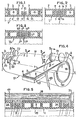
- Fig. 1 illustrates the helical winding of an extruded profile 1 made of thermoplastic plastic, for example rigid polyvinyl chloride or PVC.
- the profile 1 consists of a body 2 bordered on each side with a stapling relief 3, 4.
- the body 2 has a rectangular section with large axial sides outside 5 and inside 6 and with short radial sides 7, axial and radial extending with respect to the final tube.
- This body 2 is honeycombed or in a box, that is to say it comprises several longitudinal cavities 8 separated by partitions 9 with radial section.
- the body 2 may for example comprise four cavities 8 of rectangular section, the partitions 9 and the sides of the body having a common thickness.
- the relief 3 is a male relief. It has an L-shaped section consisting of an axial branch or web 10 and a radial branch 11.
- the first branch extends the long inner side 6 of the body 2, with the same thickness, while the second extends radially towards the outside on about half the height of a small side 7 to end in a dovetail 12.
- the relief 4 is a female relief and is made up, in section, of a part or veil 13 of connection with the body 2 which is analogous to the branch 10, located in the extension of this branch and in abutment on it in the position stapled shown. From the end of this part 13 leaves a U-shaped hook 14 outwards which turns its dovetail cavity radially inwards and which is suitable for exactly wrapping the branch 11 of the relief 3 until it comes practically into contact with the branch 10.
- the height of the assembly of the two reliefs is significantly less than that of the body 2, and its width is significantly less than the axial distance separating the short sides 7 opposite.
- the height of the assembly of the two reliefs is significantly less than that of the body 2, and its width is significantly less than the axial distance separating the short sides 7 opposite.
- the resulting tube T is therefore smooth both externally and internally, therefore insensitive to snagging or tearing during handling; in addition, the external surface of the tube can remain constantly clean because it is smooth, in particular when this tube is placed on a ground of soil and / or gravel, and the tube lends itself to assemblies by means of fittings and conventional seals. The aesthetic advantage is not negligible either.
- the winding of the profile 1 as well as the establishment of the cord 16 is preferably carried out at a temperature sufficient to ensure, in addition to their mechanical connection, a sealed connection by heat sealing of the elements 3, 4 and 16.
- glue can be used for the same purpose.
- the tube T ° of FIG. 3 does not differ from that of FIG. 2 only by the shape of the reliefs 3 ° and 4 °: the radial branch 11 of the male relief 3 ° ends in a bead 12 ° in three-quarters of a circle, and the hook 14 ° of the female relief 4 ° is rounded so conjugate.
- the concavity of the 16 ° cord is rounded correspondingly.
- Figs. 4 to 11 show a machine 17 capable of continuously producing the tube T of FIG. 2, with heat-sealing of the reliefs 3, 4 and of the cord 16.
- the modifications of this machine which are necessary to obtain the tube T ° of FIG. 3 will be obvious to those skilled in the art.
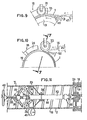
- the machine 17 essentially comprises a fixed cylindrical cage or sleeve 18 of horizontal axis XX, a coaxial mandrel 19 driven in rotation at constant speed in the direction f inside this cage, by a motor not shown, taking care with it an annular space 20, and two idler rollers 21 and 22 for guiding.
- the cage 18 At its upstream end, the cage 18 has a notch or window 23 for the entry of the profile 1 in which the roller 21 is located. Near its downstream end, but at a certain distance from the latter, the cage has a second notch or window 24, smaller than the first, for the entry of the cord 16, in which the roller 22 is located.
- the profile 1 is brought tangentially to the mandrel 19, in the window 23 and under the roller 21, at a certain angle, equal to the helix angle of the winding, relative to the axis X-X. It is delivered at constant speed by an extruder not shown or from a supply coil. Likewise, the cord 16 comes out, at constant speed, from an extruder 25 or from a supply coil to reach tangentially, in the window 24 and under the roller 22, the already wound profile.
- the cage 18 (Fig. 8) has internally over its entire length a smooth cylindrical surface partially furnished with a helical relief. This consists of upstream downstream of three successive zones: a zone 26 devoid of any relief; a zone 27 starting near the downstream end of the window 23 and ending at the upstream end of the window 24 and in which protrudes towards the axis XX a helical guide rib 28 having a U-shaped section corresponding to that cord 16 and extending over approximately two turns; and a zone 29 again devoid of any relief, the part of the cage 18 located downstream of the second window 24 extending over approximately one revolution.
- the mandrel 19 has, over its entire length, a cylindrical, striated outer surface. longitudinally to improve the drive of the profile 1. However, in line with zone 29, this surface converges slightly downstream to facilitate the exit of the tube T produced.
- the mandrel 19 is extended beyond the downstream end of the cage by a device 30 for extracting and guiding the tube T (FIG. 11).
- the downstream end of the mandrel 19 is secured in rotation and in axial translation with the driving element of a universal joint 31.
- the two driving and driven elements of the joint 31 are capable of rotating around the axis. XX with a slight angular deviation in order to give flexibility in guiding the tube T at the outlet of the cage 18.
- the driven element of the universal joint 31 is integral with a shaft 32 on which a sleeve or ring is fixed cylindrical 33 for support and internal guide of the tube T.
- the sleeve 33 rotates with the shaft 32 by virtue of a connection constituted for example by a spindle which runs right through the shaft 32 and a hub 34 of the sleeve 33.
- the shaft 32 is also provided with an expander 35 with rollers 36 of axes orthogonal to the axis of the shaft 32, for example two in number diametrically opposed, carried by levers 37 articulated in their middle and intended to separate the rollers 36 (position in solid lines) or to bring them closer (position in broken lines) to the axis XX, and consequently to press these rollers more or less on the internal wall of the tube T.
- the spacing of these rollers 36 is adjusted by means of a nut 38 on which the downstream ends of the levers 37 are articulated.
- the nut 38 is screwed onto a screw 39 operated by a handwheel 40 and extending the shaft 32, on the end of which the upstream ends of the levers 37 are articulated.
- Oblique rollers 41 of the external support are finally provided in line with the sleeve 33.
- the angle of the rollers 41 relative to the axis XX corresponds at the helix angle of the winding.
- the roller 21 for guiding the profile 1 (FIG. 6) of axis Y-Y perpendicular to the oblique arrival of the profile 1, has a profile roughly combined with the outside profile of the latter. It thus has a cylindrical part corresponding to the honeycombed body 2 and providing a slight radial clearance therewith, an upstream end cheek 42 being introduced without play into the space provided between the male relief 3 and the body 3 and, at the other end, a pair of identical cheeks 43 separated by a circular groove 44 receiving without play the female clip 14 of the profile 1. The free downstream edge of the relief 4 then is flush with the edge of the downstream cheek 43.
- the roller 22 for guiding the cord 16 (FIG. 7) with an axis ZZ oblique to the axis XX and perpendicular to the oblique arrival of this cord, comprises a pair of identical cheeks 45 delimiting between them a circular groove 46 into which the cord 16 fits without play, the branches of the latter then being flush with the edge of the cheeks 45.
- the mandrel 19 is rotated at a speed which is harmonized with the exit speed of the extruder, not shown, producing the section 1 according to arrow g (Fig. 4).
- the means, indicated above, for measuring the deflection of the loop B formed by the section 1 between its extruder outlet and the cage 18 (Fig. 9) are also used to adjust the relative speeds: when the deflection increases ( excess of the extrusion speeds relative to the winding speed), the extrusion speed is reduced (or the speed of rotation of the mandrel 19 is increased); conversely, when the deflection decreases (excess winding speed relative to the extrusion speed), the extrusion speed is increased (or the speed of rotation of the mandrel 19 is reduced).
- This regulation is carried out automatically by known means, not shown.
- the profile 1 is manually introduced under the roller 21 and into the cage 18. Then this profile continues its movement by itself, driven by the rotation of the mandrel 19 on which it is applied by the roller 21
- the entry of the profile 1 into the cage takes place tangentially to this cage and to the mandrel, through the window 23, and obliquely with respect to the axis XX, with an inclination which is that of the winding propeller.
- the male relief 3 is preferably located upstream, so that the female relief 4 first enters the closed area 27 of the cage 18.
- the profile 1 is guided by the roller 21, which rolls freely on it as on a rail, its cheek 42 positioning the male clip 3 and its cheeks 43 as well as its groove 44 positioning its female clip 4.
- the roller 21 applies the areas of contact of the profile by its cheeks 42 and 43 and its groove 44, so as to facilitate the drive of the profile by the mandrel while guiding the profile.
- the section 1 comes exactly into engagement with the helical rib 28 and its body 2 comes to fit into the space separating the turns of this rib.
- the profile and the cage engage like a screw (profile) in a nut (cage 18). As the cage is fixed, the profile 1 progresses in rotation and in translation in a helical movement.
- the first formed whorl reaches the notch 24 and enters the zone 29 of the cage 18, with a smooth wall devoid of helical rib.
- the primer of the cord 16 is introduced manually into the groove 46 of the roller 22 and into the space 15 surrounding the first turn of the stapling 3-4, this introduction taking place tangentially with respect to the mandrel 19 and obliquely with respect to axis XX, with an inclination which is that of the winding propeller.
- the cord 16, driven by the mandrel is housed at the bottom of the groove 46 and comes, at the end of the window 24, to be introduced into the helical groove 15 by covering the stapling 3-4.
- the cheeks 45 of the roller 22 roll on the edges opposite the adjacent turns of the body 2.
- the cord 16 comes to completely occupy this groove 15 by being flush the outer wall 5 of the adjacent turns. It is the cage 18 which locks the cord 16 on the stapling 3-4 and it is the absence of internal helical relief in the zone 29 of the cage which allows the introduction of the cord 16 into the cage.
- the flow rate of the extruder 25 is automatically adjusted as a function of the speed of rotation of the mandrel 19.
- this tube is still supported and driven in positive rotation by the extraction device 30, its translation being effected by the screw-nut movement formed by the groove helical 15 separating the coiled turns of the profile 1 and the helical rib 28 of the cage.
- the tube T is supported, at a certain distance beyond the cage 18, by the sleeve 33 and the rollers 41.
- the sleeve 33 integral in rotation with the mandrel 19 by means of the universal joint 31, does not offers no friction resistance to the rotation of the tube T.
- the tube T is itself positively rotated by the expander 35, the rollers 36 of which are suitably applied to the inner wall of the tube T by appropriate adjustment of the nut 38 by means of the handwheel 40.
- the oblique arrangement of the rollers 36 also allows the helical movement of the tube T.
- the tube T can be cut downstream.
Description
La présente invention est relative à la fabrication de corps tubulaires en matière thermoplastique par enroulement en hélice d'un profilé constitué d'un corps à section rectangulaire muni sur chaque bord d'un relief d'agrafage, l'un mêle et l'autre femelle. Ces tubes, rigides et légers, peuvent avoir un diamètre nettement supérieur aux diamètres maximaux que l'on peut extruder directement sous forme de tubes.The present invention relates to the manufacture of tubular bodies of thermoplastic material by helically winding a profile consisting of a body of rectangular section provided on each edge with a stapling relief, one mixed and the other female. These rigid and light tubes can have a diameter much greater than the maximum diameters which can be extruded directly in the form of tubes.
Dans une demande de brevet européen déposée le 08.08.80 et publiée sous le n° 0025 121, la Demanderesse a décrit un tube de ce type dans lequel chaque relief comporte un voile axial de support qui prolonge l'une des surfaces extérieure et intérieure du corps du profilé, les deux voiles adjacents étant en butée et les deux reliefs en prise définissant avec les bords adjacents du corps du profilé un espace à section en U occupé par un cordon de section complémentaire.In a European patent application filed on 08.08.80 and published under the number 0025 121, the Applicant has described a tube of this type in which each relief comprises an axial support veil which extends one of the outer and inner surfaces of the body of the profile, the two adjacent webs being in abutment and the two reliefs in engagement defining with the adjacent edges of the body of the profile a U-section space occupied by a cord of complementary section.
Grâce à cet agencement, on obtient un tube dont la paroi est lisse extérieurement aussi bien qu'intérieurement.Thanks to this arrangement, a tube is obtained whose wall is smooth externally as well as internally.
On connatt des machines de fabrication en continu de tubes en matière plastique obtenus par enroulement en hélice d'un profilé constitué d'un corps à section rectangulaire muni sur chaque bord d'un relief d'agrafage, l'un mâle et l'autre femelle ménageant une gorge. Ces machines comprennent généralement une cage cylindrique fixe munie d'une fenêtre d'entrée du profilé combinée à un galet de guidage de ce profilé et, à partir de cette fenêtre, d'un relief intérieur hélicoïdal de guidage de la gorge du profilé, un mandrin coaxial monté rotatif dans cette cage, et un dispositif d'extraction disposé à la sortie de la cage. Cette cage joue le rôle d'un écrou fixe par rapport au profilé jouant le rôle d'une vis rotative au cours du formage du tube. Ceci est connu par le brevet FR 1 212735.We know machines for the continuous production of plastic tubes obtained by helically winding a profile consisting of a body of rectangular section provided on each edge with a stapling relief, one male and the other female sparing a throat. These machines generally include a fixed cylindrical cage provided with a profile entry window combined with a guide roller for this profile and, from this window, with a helical internal relief for guiding the profile groove, a coaxial mandrel rotatably mounted in this cage, and an extraction device disposed at the outlet of the cage. This cage plays the role of a fixed nut relative to the profile playing the role of a rotary screw during the forming of the tube. This is known from patent FR 1 212735.
Des machines de ce type ne permettent pas de fabriquer un tube lisse extérieurement puisque le profilé plastique à enrouler doit comporter obligatoirement une gorge de forme conjuguée de celle du relief hélicoïdal de la cage. Des machines de ce type ne permettent pas non plus l'enroulement hélicoïdal d'un cordon de remplissage de la gorge du profilé car le cordon ne trouverait pas place entre la cage et le profilé. Or, pour fabriquer le tube suivant la demande de brevet antérieure précitée, il faut assurer un bon accostage des spires à agrafer et une application bien guidée du cordon de verrouillage des agrafes en remplissant la gorge de manière à rendre le tube lisse extérieurement.Machines of this type do not make it possible to manufacture a smooth tube externally since the plastic profile to be wound must necessarily include a groove of shape conjugate with that of the helical relief of the cage. Machines of this type also do not allow the helical winding of a filler cord for the groove of the profile because the cord would not find a place between the cage and the profile. However, to manufacture the tube according to the aforementioned prior patent application, it is necessary to ensure good docking of the turns to be stapled and a well guided application of the staple locking cord by filling the groove so as to make the tube smooth externally.
L'invention a pour but de fournir une machine du même type capable de résoudre ce problème difficile, c'est-à-dire de fabriquer en continu un tube tel que décrit dans la demande de brevet précitée.The invention aims to provide a machine of the same type capable of solving this difficult problem, that is to say of continuously manufacturing a tube as described in the aforementioned patent application.
A cet effet, l'invention a pour objet une machine du type précité, caractérisée en ce que le relief de la cage a une section en U à peu près identique à celle du cordon et en ce qu'en aval de ce relief la cage dépourvue de tout relief interne comporte une seconde fenêtre d'entrée du cordon combinée à un galet de guidage de ce cordon.To this end, the subject of the invention is a machine of the aforementioned type, characterized in that the relief of the cage has a U-shaped section roughly identical to that of the cord and in that downstream of this relief the cage devoid of any internal relief comprises a second cord entry window combined with a guide roller for this cord.
D'autres caracteristiques et avantages de l'invention ressortiront de la description qui va suivre, donnée à titre d'exemple non limitatif et en regard des dessins annexés, sur lesquels:
- la Fig. 1 est une vue partielle en coupe axiale d'un tube réalisé au moyen d'une machine suivant l'invention, en cours de fabrication;
- la Fig. 2 est une vue analogue du tube terminé;
- la Fig. 3 est une vue analogue d'une variante du tube de la Fig. 2;
- la Fig. 4 est une vue schématique en perspective d'une machine suivant l'invention destinée à la fabrication du tjbe de la Fig. 2;
- les Fig. 5, 8 et 9 sont des vues partielles prises respectivement suivant les lignes 5-5, 8-8 et 9-9 de la Fig. 4;
- les Fig. 6 et 7 sont respectivement des vues des galets de guidage du profilé et du cordon;
- la Fig. 10 illustre en bout la mise en place du cordon;
- la Fig. 11 est une vue en coupe axiale du dispositif d'extraction et de guidage du tube.
- Fig. 1 is a partial view in axial section of a tube produced by means of a machine according to the invention, during manufacture;
- Fig. 2 is a similar view of the finished tube;
- Fig. 3 is a similar view of a variant of the tube of FIG. 2;
- Fig. 4 is a schematic perspective view of a machine according to the invention intended for the manufacture of the tjbe of FIG. 2;
- Figs. 5, 8 and 9 are partial views taken respectively along lines 5-5, 8-8 and 9-9 of FIG. 4;
- Figs. 6 and 7 are respectively views of the guide rollers of the profile and of the bead;
- Fig. 10 illustrates at the end the establishment of the cord;
- Fig. 11 is an axial section view of the device for extracting and guiding the tube.
La Fig. 1 illustre l'enroulement en hélice d'un profilé 1 extrudé en matière plastique thermoplastique, par exemple en chlorure de poly- vinyle rigide ou PVC. Le profilé 1 est constitué d'un corps 2 bordé de chaque côté d'un relief d'agrafage 3, 4.Fig. 1 illustrates the helical winding of an extruded profile 1 made of thermoplastic plastic, for example rigid polyvinyl chloride or PVC. The profile 1 consists of a
Le corps 2 a une section rectangulaire à grands côtés axiaux extérieure 5 et intérieur 6 et à petits côtés radiaux 7, axiaux et radiaux s'étendant par rapport au tube final. Ce corps 2 est alvéolé ou en caisson, c'est-à-dire qu'il comporte plusieurs cavités longitudinales 8 séparées par des cloisons 9 à section radiale. Le corps 2 peut par exemple comporter quatre cavités 8 à section rectangulaire, les cloisons 9 et les côtés du corps ayant une épaisseur commune.The
Le relief 3 est un relief mâle. Il comporte une section en L constituée d'une branche ou voile axial 10 et d'une branche radiale 11. La première branche prolonge le grand côté intérieur 6 du corps 2, avec la même épaisseur, tandis que la seconde s'étend radialement vers l'extérieur sur environ la moitié de la hauteur d'un petit côté 7 pour se terminer en une queue d'aronde 12.The
Le relief 4 est un relief femelle et est constitué, en section, d'une partie ou voile 13 de liaison avec le corps 2 qui est analogue à la branche 10, situé dans le prolongement de cette branche et en butée sur elle dans la position agrafée représentée. De l'extrémité de cette partie 13 part vers l'extérieur un crochet en U 14 qui tourne radialement vers l'intérieur sa cavité en queue d'aronde et qui est adapté pour envelopper exactement la branche 11 du relief 3 jusqu'à venir pratiquement au contact de la branche 10.The
Dans la position agrafée, la hauteur de l'ensemble des deux reliefs est nettement inférieure à celle du corps 2, et sa largeur est nettement inférieure à la distance axiale séparant les petits côtés 7 en regard. Ainsi est défini entre ces derniers et autour du crochet 14 un espace libre 15 en U.In the stapled position, the height of the assembly of the two reliefs is significantly less than that of the
Pour terminer le tube T (Fig. 2), on dispose dans l'espace 15 un cordon 16 en matière plastique thermoplastique rigide, telle que le PVC, de section en U complémentaire. Ce cordon vient donc coiffer l'ensemble des deux reliefs 3, 4, et sa surface extérieure affleure celle des deux parties adjacentes du corps 2 du profilé.To complete the tube T (FIG. 2), there is in the space 15 a
Le tube T résultant est donc lisse aussi bien extérieurement qu'intérieurement, donc peu sensible à des accrochages ou à des déchirures lors de manutentions; en outre, la surface extérieure du tube peut rester constamment propre du fait qu'elle est lisse, notamment lorsque ce tube est posé sur un sol de terre et/ou de gravier, et le tube se prête à des assemblages au moyens des raccords et garnitures d'étanchéité classiques. L'avantage esthétique n'est pas non plus négligeable.The resulting tube T is therefore smooth both externally and internally, therefore insensitive to snagging or tearing during handling; in addition, the external surface of the tube can remain constantly clean because it is smooth, in particular when this tube is placed on a ground of soil and / or gravel, and the tube lends itself to assemblies by means of fittings and conventional seals. The aesthetic advantage is not negligible either.
De plus, les spires ne risquent pas de se séparer les unes des autres grâce d'une part à l'agrafage positif 12-14 et d'autre part au verrouillage de cet agrafage assuré par le cordon 16.In addition, the turns are not likely to separate from each other thanks on the one hand to the positive stapling 12-14 and on the other hand to the locking of this stapling provided by the
L'enroulement du profilé 1 ainsi que la mise en place du cordon 16 s'effectuent de préférence à une température suffisante pour assurer, en plus de leur solidarisation mécanique, une solidarisation étanche par thermosoudage des éléments 3, 4 et 16. En variante, on peut utiliser une colle dans le même but.The winding of the profile 1 as well as the establishment of the
Le tube T° de la Fig. 3 ne diffère de celui de la Fig. 2 que par la forme des reliefs 3° et 4°: la branche radiale 11 du relief mâle 3° se termine par un bourrelet 12° en trois-quarts de cercle, et le crochet 14° du relief femelle 4° est arrondi de façon conjuguée. La concavité du cordon 16° est arrondie de façon correspondante.The tube T ° of FIG. 3 does not differ from that of FIG. 2 only by the shape of the
Les Fig. 4 à 11 représentent une machine 17 capable de réaliser en continu le tube T de la Fig. 2, avec thermosoudage des reliefs 3, 4 et du cordon 16. Les modifications de cette machine qui sont nécessaires pour obtenir le tube T° de la Fig. 3 seront évidentes pour l'homme de l'art.Figs. 4 to 11 show a
La machine 17 comprend essentiellement une cage ou manchon cylindrique fixe 18 d'axe X-X horizontal, un mandrin coaxial 19 entraîné en rotation à vitesse constante dans le sens f à l'intérieure de cette cage, par un moteur non représenté, en ménageant avec elle un espace annulaire 20, et deux galets fous 21 et 22 de guidage.The
A son extrémité amont, la cage 18 présente une échancrure ou fenêtre 23 pour l'entrée du profilé 1 dans laquelle est situé le galet 21. Près de son extrémité aval, mais à une certaine distance de celle-ci, la cage comporte une seconde échancrure ou fenêtre 24, plus petite que la première, pour l'entrée du cordon 16, dans laquelle est situé le galet 22.At its upstream end, the
Le profilé 1 est amené tangentiellement sur le mandrin 19, dans la fenêtre 23 et sous le galet 21, suivant un certain angle, égal à l'angle d'hélice de l'enroulement, par rapport à l'axe X-X. Il est débité à vitesse constante par une extrudeuse non représentée ou à partir d'une bobine d'alimentation. De même, le cordon 16 sort, à vitesse constante, d'une extrudeuse 25 ou d'une bobine d'alimentation pour atteindre tangentiellement, dans la fenêtre 24 et sous le galet 22, le profilé déjà enroulé.The profile 1 is brought tangentially to the
La cage 18 (Fig. 8) présente intérieurement sur toute sa longueur une surface cylindrique lisse partiellement garnie d'un relief hélicoïdal. Celle-ci se compose d'amont en aval de trois zones successives: une zone 26 dépourvue de tout relief; une zone 27 commençant près de l'extrémité aval de la fenêtre 23 et se terminant à l'extrémité amont de la fenêtre 24 et dans laquelle fait saillie vers l'axe X-X une nervure hélicoïdale de guidage 28 ayant une section en U correspondant à celle du cordon 16 et s'étendant sur environ deux tours; et une zone 29 de nouveau dépourvue de tout relief, la partie de la cage 18 située en aval de la seconde fenêtre 24 s'étendant sur environ un tour.The cage 18 (Fig. 8) has internally over its entire length a smooth cylindrical surface partially furnished with a helical relief. This consists of upstream downstream of three successive zones: a
Le mandrin 19 a, sur toute sa longueur, une surface extérieure cylindrique, striée. longitudinalement pour améliorer l'entraînement du profilé 1. Toutefois, au droit de la zone 29, cette surface converge légèrement vers l'aval pour faciliter la sortie du tube T réalisé.The
Le mandrin 19 est prolongé au-delà de l'extrémité aval de la cage par un dispositif 30 d'extraction et de guidage du tube T (Fig. 11 ).The
A cet effet, l'extrémité aval du mandrin 19 est solidarisée en rotation et en translation axiale avec l'élément menant d'un joint de cardan 31. Les deux éléments menant et mené du joint 31 sont susceptibles de tourner autour de l'axe X-X avec une légère déviation angulaire en vue de donner de la souplesse au guidage du tube T à la sortie de la cage 18. L'élément mené du joint de cardan 31 est solidaire d'un arbre 32 sur lequel est fixé un manchon ou anneau cylindrique 33 de support et de guidage interne du tube T. Le manchon 33 tourne avec l'arbre 32 grâce à une solidarisation constituée par exemple par une broche qui traverse de part en part l'arbre 32 et un moyeu 34 du manchon 33.To this end, the downstream end of the
L'arbre 32 est muni également d'un expanseur 35 à galets 36 d'axes orthogonaux à l'axe de l'arbre 32, par exemple au nombre de deux diamétralement opposés, portés par des leviers 37 articulés en leur milieu et destinés à écarter les galets 36 (position en trait plein) ou à les rapprocher (position en trait interrompu) de l'axe X-X, et par conséquent à presser plus ou moins ces galets sur la paroi interne du tube T. Le réglage de l'écartement de ces galets 36 s'effectue au moyen d'un écrou 38 sur lequel sont articulées les extrémités aval des leviers 37. L'écrou 38 est vissé sur une vis 39 manoeuvrée par un volant 40 et prolongeant l'arbre 32, sur l'extrémité duquel sont articulées les extrémités amont des leviers 37. Des galets obliques 41 des support extérieure sont enfin prévus au droit du manchon 33. L'angle des galets 41 par rapport à l'axe X-X correspond à l'angle d'hélice de l'enroulement.The
Le galet 21 de guidage du profilé 1 (Fig. 6) d'axe Y-Y perpendiculaire à l'arrivée oblique du profilé 1, a un profil à peu près conjugué du profil extérieur de celui-ci. Il possède ainsi une partie cylindrique correspondant au corps alvéolé 2 et ménageant un léger jeu radial avec celui-ci, une joue d'extrémité amont 42 s'introduisant sans jeu dans l'espace menagé entre le relief mâle 3 et le corps 3 et, à l'autre extrémité, une paire de joues identiques 43 séparées par une gorge circulaire 44 recevant sans jeu l'agrafe femelle 14 du profilé 1. Le bord aval libre du relief 4 affleure alors de bord de la joue 43 aval.The
Le galet 22 de guidage du cordon 16 (Fig. 7) d'axe Z-Z oblique par rapport à l'axe X-X et perpendiculaire à l'arrivée oblique de ce cordon, comporte une paire de joues identiques 45 délimitant entre elles une gorge circulaire 46 dans laquelle s'insère sans jeu le cordon 16, les branches de celui-ci affleurant alors le bord des joues 45.The
La machine 17 comporte en outre des moyens de régulation de la température:
- - un organe de chauffage 47, par exemple à résistance électrique, est placé sous le profilé 1, un peu avant sont entrée dans la
cage 18, afin de rendre ce profilé plus malléable et plus déformable. Grâce à cet organe 47, le profilé 1 forme une boucle d'affaissement (Fig. 9) dont on mesure la flèche afin de régler la température de chauffage de l'organe 47: si la flèche s'accentue, il faut baisser la température de l'organe 47; si la flèche diminue, il faut en augmenter la température; - - un autre organe de chauffage, par exemple un ajutage d'air chaud 48 (Fig. 9) placé entre le mandrin 19 et le profilé 1, sous le galet 21 et près de ses joues 43, ramollit les
reliefs 3et 4 pour permettre leur soudage; - -
le mandrin 19 est pourvu intérieurement d'une circulation de fluide (non représentée); - - il en est de même de la
cage 18, dont la paroi est creuse (chambre 49 des Fig. 5 et 8). Cette circulation fournit une température appropriée pour que, dans la cage, le durcissement de la matière plastique ne s'opère pas mais commence seulement; - - un autre organe de chauffage, par exemple un ajutage d'air chaud 50 (Fig. 1 et 10), placé entre le mandrin 19 et le
cordon 16, sous le galet 22, amène les surfaces en regard desreliefs 3et 4 et ducordon 16 à une température suffisante pour permettre leur soudage.
- - A
heater 47, for example with electrical resistance, is placed under the profile 1, a little before entered thecage 18, in order to make this profile more malleable and more deformable. Thanks to thismember 47, the profile 1 forms a subsidence loop (Fig. 9) whose deflection is measured in order to adjust the heating temperature of the member 47: if the deflection increases, the temperature must be loweredorgan 47; if the arrow decreases, the temperature must be increased; - - another heating element, for example a hot air nozzle 48 (Fig. 9) placed between the
mandrel 19 and the profile 1, under theroller 21 and near itscheeks 43, softens thereliefs - the
mandrel 19 is internally provided with a circulation of fluid (not shown); - - the same applies to the
cage 18, the wall of which is hollow (chamber 49 of FIGS. 5 and 8). This circulation provides an appropriate temperature so that, in the cage, the hardening of the plastic does not take place but only begins; - - another heating element, for example a hot air nozzle 50 (Fig. 1 and 10), placed between the
mandrel 19 and thecord 16, under theroller 22, brings the surfaces facing thereliefs cord 16 at a temperature sufficient to allow them to be welded.
Soit à fabriquer un tube T par enroulement en hélice du profilé 1 puis du cordon 16.Either to manufacture a tube T by helically winding profile 1 then
Le mandrin 19 est entraîné en rotation à une vitesse qui est harmonisée avec la vitesse de sortie de l'extrudeuse, non représentée, produisant le profilé 1 suivant la flèche g (Fig. 4). Les moyens, indiqués plus haut, de mesure de la flèche de la boucle B que forme le profilé 1 entre sa sortie d'extrudeuse et la cage 18 (Fig. 9) sont également utilisés pour régler les vitesses relatives: quand la flèche augmente (excédent des vitesses d'extrusion par rapport à la vitesse d'enroulement), la vitesse d'extrusion est diminuée (ou la vitesse de rotation du mandrin 19 est augmentée); inversement, quand la flèche diminue (excédent de vitesse d'enroulement par rapport à la vitesse d'extrusion), la vitesse d'extrusion est augmentée (ou la vitesse de rotation du mandrin 19 est diminuée). Cette régulation s'effectue automatiquement par des moyens connus, non représentés.The
Au démarrage de l'installation, on introduit manuellement le profilé 1 sous le galet 21 et dans la cage 18. Puis ce profilé continue de lui-même son mouvement, entraîné par la rotation du mandrin 19 sur lequel il est appliqué par le galet 21. L'entrée du profilé 1 dans la cage (Fig. 9) s'effectue tangentiellement à cette cage et au mandrin, par la fenêtre 23, et obliquement par rapport à l'axe X-X, avec une inclinaison qui est celle de l'hélice d'enroulement. Comme représenté, le relief mâle 3 est de préférence situé à l'amont, de sorte que le relief femelle 4 pénètre le premier dans la zone fermée 27 de la cage 18. Juste avant d'entrer dans la cage 18, le profilé 1 est guidé par le galet 21, qui roule librement sur lui comme sur un rail, sa joue 42 positionnant l'agrafe mâle 3 et ses joues 43 ainsi que sa gorge 44 positionnant son agrafe femelle 4. Le galet 21 applique sur le mandrin les zones de contact du profilé par ses joues 42 et 43 et sa gorge 44, de façon à faciliter l'entraînement du profilé par le mandrin tout en guidant le profilé.At the start of the installation, the profile 1 is manually introduced under the
Grâce à ce guidage précis par le galet 21, le profilé 1 vient exactement en prise avec la nervure hélicoïdale 28 et son corps 2 vient s'emboîter dans l'espace séparant les spires de cette nervure. Ainsi, le profilé et la cage se mettent en prise comme une vis (profilé) dans un écrou (cage 18). Comme la cage est fixe, le profilé 1 progresse en rotation et en translation suivant un mouvement hélicoïdal.Thanks to this precise guidance by the
Lorsque la première spire du profilé est enroulée, la portion de celui-ci entrant dans la cage 18 commence à former une seconde spire qui, grâce au guidage du galet 21, accoste la première spire, emboîte son agrafe femelle 4 sur l'agrafe mêle 3 de la première spire déjà formée, au droit du galet 21, grâce à l'action de ce galet et de la nervure de guidage 28. Cet agrafage 3-4, soumis à un soufflage d'air chaud par l'ajutage 48, se soude au fur et à mesure de l'enroulement dans la cage 18, qui va consolider cet agrafage et donner aux spires enroulées une forme parfaitement cylindrique. Le galet 21, par la pression et le guidage qu'il exerce au moyen de ses joues 43 et de sa gorge 44 sur les parties agrafées, chauffées, facilite cette soudure.When the first turn of the profile is wound, the portion of it entering the
Dans la zone 27 de la cage 18 vont ainsi s'enrouler, avec un léger jeu radial extérieur mais sans jeu axial (Fig. 5), par exemple deux spires agrafées, qui passent ensuite dans la zone aval 29 de la cage, où s'effectue la finition de l'assemblage par mise en place du cordon 16.In the
Progressant ainsi dans la cage 18, la première spire formée atteint l'échancrure 24 et entre dans la zone 29 de la cage 18, à paroi lisse dépourvue de nervure hélicoïdale.Progressing thus in the
L'amorce du cordon 16 est introduite manuellement dans la gorge 46 du galet 22 et dans l'espace 15 entourant la première spire de l'agrafage 3-4, cette introduction s'effectuant tangentiellement par rapport au mandrin 19 et obliquement par rapport à l'axe X-X, avec une inclinaison qui est celle de l'hélice d'enroulement. Le cordon 16, entraîné par le mandrin, se loge au fond de la gorge 46 et vient, à l'extrémité de la fenêtre 24, s'introduire dans la rainure hélicoïdale 15 en coiffant l'agrafage 3-4. Pendant cet enroulement, les joues 45 du galet 22 roulent sur les bords en regard des spires adjacentes du corps 2. Ainsi, grâce à la cage 18 et au guidage assuré par le galet 22, le cordon 16 vient occuper complètement cette rainure 15 en affleureant la paroi extérieure 5 des spires adjacentes. C'est la cage 18 qui verrouille le cordon 16 sur l'agrafage 3-4 et c'est l'absence de relief hélicoïdal interne dans la zone 29 de la cage qui permet l'introduction du cordon 16 dans la cage.The primer of the
Bien entendu, le débit de l'extrudeuse 25 est réglé automatiquement en fonction de la vitesse de rotation du mandrin 19.Of course, the flow rate of the
Comme l'ajutage d'air chaud 49 ramollit la surface intérieure du cordon 16 et la surface extérieure de l'agrafage 3-4, une soudure se fait à l'intérieur de la cage 18, dans la zone 29, contre la paroi intérieure lisse de celle-ci, qui parfait l'emboîtement du cordon 16 sur l'agrafage 3-4 et lui donne une forme extérieure cylindrique. Le cordon 16 s'enroule dans la zone 29 de la cage 18 sur preque un tour complet, puis le tube final T, formé et agrafé, sort de la cage 18.As the
En vue d'éviter toute déformation du tube T fraîchement enroulé, agrafé et soudé, ce tube est encore supporté et entraîné en rotation positivement par le dispositif d'extraction 30, sa translation s'effectuant grâce au mouvement vis-écrou constitué par la rainure hélicoïdale 15 séparant les spires enroulées du profilé 1 et la nervure hélicoïdale 28 de la cage.In order to avoid any deformation of the freshly wound, stapled and welded tube T, this tube is still supported and driven in positive rotation by the
A cet effet, le tube T est supporté, à une certaine distance au-delà de la cage 18, par le manchon 33 et les galets 41. Le manchon 33, solidaire en rotation du mandrin 19 grâce au joint de cardan 31, n'oppose aucune résistance de frottement à la rotation du tube T. Le tube T est lui-même positivement entraîné en rotation par l'expanseur 35, dont les galets 36 sont convenablement appliqués sur la paroi intérieure du tube T par réglage approprié de l'écrou 38 au moyen du volant 40. La disposition oblique des galets 36 permet également le mouvement hélicoïdal du tube T.To this end, the tube T is supported, at a certain distance beyond the
Enfin, le tube T peut être tronçonné en aval.Finally, the tube T can be cut downstream.
Grâce à l'introduction tardive du cordon 16, il est possible de mettre en place en continu ce cordon tout en bénéficiant du mouvement vis-écrou assuré par la coopération de la nervure 28 et des spires du profilé 1 pour faire progresser en translation le tube T, et donc de bénéficier d'un excellent guidage et d'une excellente régularité de formage et d'assemblage des spires du tube T. Dès la fin de ce guidage, c'est-à-dire au début de la zone 29 de la cage, la nervure 28 est remplacée par le cordon 16.Thanks to the late introduction of the
Grâce à l'entraînement positif en rotation du tube T à sa sortie de la cage d'enroulement, au moyen de l'expanseur rotatif 35, du support rotatif 33 et de l'accouplement en rotation 31 avec le mandrin rotatif 19, le tube T ne subit aucune contrainte de torsion.By virtue of the positive drive in rotation of the tube T at its exit from the winding cage, by means of the
Claims (10)
Applications Claiming Priority (2)
| Application Number | Priority Date | Filing Date | Title |
|---|---|---|---|
| FR7923794 | 1979-09-25 | ||
| FR7923794A FR2465581A1 (en) | 1979-09-25 | 1979-09-25 | CONTINUOUS MANUFACTURE OF PLASTIC TUBES BY HELICOIDAL WINDING |
Publications (2)
| Publication Number | Publication Date |
|---|---|
| EP0025971A1 EP0025971A1 (en) | 1981-04-01 |
| EP0025971B1 true EP0025971B1 (en) | 1983-05-04 |
Family
ID=9229974
Family Applications (1)
| Application Number | Title | Priority Date | Filing Date |
|---|---|---|---|
| EP80105563A Expired EP0025971B1 (en) | 1979-09-25 | 1980-09-17 | Machine for the continuous production of plastics tubes by helicoidal winding |
Country Status (3)
| Country | Link |
|---|---|
| EP (1) | EP0025971B1 (en) |
| DE (1) | DE3062974D1 (en) |
| FR (1) | FR2465581A1 (en) |
Cited By (3)
| Publication number | Priority date | Publication date | Assignee | Title |
|---|---|---|---|---|
| WO2005106308A1 (en) * | 2004-04-30 | 2005-11-10 | Gemma Corporation Pty Ltd | Manufacture of reinforced tubular products of predetermined length |
| WO2005106315A1 (en) * | 2004-04-30 | 2005-11-10 | Gemma Corporation Pty Ltd | Manufacture of flexible tubular duct with improved core delivery |
| CN108000858A (en) * | 2017-12-12 | 2018-05-08 | 安徽蕴通管业科技有限公司 | A kind of HDPE winding pipe production equipment |
Families Citing this family (8)
| Publication number | Priority date | Publication date | Assignee | Title |
|---|---|---|---|---|
| CA1282571C (en) * | 1986-07-03 | 1991-04-09 | Stanley William Otto Menzel | Method of and means for producing reinforced ribbed structures |
| AU598625B2 (en) * | 1986-11-26 | 1990-06-28 | Danby Pty Ltd | Method of and machine for winding tubes from strip |
| DE3931613C1 (en) * | 1989-09-22 | 1990-09-20 | Petzetakis, George Aristovoulos, Piraeus, Gr | |
| AU2005238550C1 (en) * | 2004-04-30 | 2014-03-06 | Nova-Duct Technologies Pty Ltd | Manufacture of reinforced tubular products of predetermined length |
| CN106764126B (en) * | 2017-01-25 | 2019-03-29 | 高其容 | A kind of HDPE hollow wall wound drain pipe production equipment and method |
| CN110001040A (en) * | 2019-05-08 | 2019-07-12 | 杭州越歌科技有限公司 | A kind of winding structure pipe and its manufacturing device |
| CN113002033B (en) * | 2021-03-10 | 2022-01-11 | 海宁亚大塑料管道系统有限公司 | Compression-resistant winding pipe and production device and process thereof |
| CN116753394B (en) * | 2023-08-22 | 2023-10-31 | 江西强发科技有限公司 | Winding pipeline repairing device |
-
1979
- 1979-09-25 FR FR7923794A patent/FR2465581A1/en active Granted
-
1980
- 1980-09-17 EP EP80105563A patent/EP0025971B1/en not_active Expired
- 1980-09-17 DE DE8080105563T patent/DE3062974D1/en not_active Expired
Non-Patent Citations (1)
| Title |
|---|
| Néant * |
Cited By (4)
| Publication number | Priority date | Publication date | Assignee | Title |
|---|---|---|---|---|
| WO2005106308A1 (en) * | 2004-04-30 | 2005-11-10 | Gemma Corporation Pty Ltd | Manufacture of reinforced tubular products of predetermined length |
| WO2005106315A1 (en) * | 2004-04-30 | 2005-11-10 | Gemma Corporation Pty Ltd | Manufacture of flexible tubular duct with improved core delivery |
| CN108000858A (en) * | 2017-12-12 | 2018-05-08 | 安徽蕴通管业科技有限公司 | A kind of HDPE winding pipe production equipment |
| CN108000858B (en) * | 2017-12-12 | 2020-05-19 | 安徽蕴通管业科技有限公司 | HDPE winding pipe production facility |
Also Published As
| Publication number | Publication date |
|---|---|
| FR2465581A1 (en) | 1981-03-27 |
| EP0025971A1 (en) | 1981-04-01 |
| DE3062974D1 (en) | 1983-06-09 |
| FR2465581B1 (en) | 1981-10-02 |
Similar Documents
| Publication | Publication Date | Title |
|---|---|---|
| EP0025971B1 (en) | Machine for the continuous production of plastics tubes by helicoidal winding | |
| CA2297763C (en) | Flexible conduit, such as pipe for medical or surgical use | |
| EP3458767B1 (en) | Vessel made of composite material for containing a pressurised fluid | |
| EP0148061B1 (en) | Apparatus for the continuous manufacture of a tubular structure of helically wound interlocking strip material | |
| EP0025121B1 (en) | Plastic tube obtained by helicoidal winding of a profile | |
| FR2547766A1 (en) | METHOD AND APPARATUS FOR MANUFACTURING ONDULATED TUBES | |
| WO2001072499A1 (en) | Method and continuous production line of plastic tubes with bi-axial drawing, and resulting plastic tube | |
| FR2486448A1 (en) | METHOD AND APPARATUS FOR MANUFACTURING POLYMER-REINFORCED FLEXIBLE PIPES | |
| FR3001656A1 (en) | IMPROVED MANUFACTURING METHOD OF A TRANSMISSION SHAFT, PREFERABLY FOR AN AIRCRAFT TURBOMACHINE ACCESSORY BOX SYSTEM | |
| BE623129A (en) | ||
| EP0036381B1 (en) | Method of forming profiles, especially tubular profiles | |
| EP0310499A1 (en) | Method and device for the production of a corrugated fibre structure for use as a reinforcing structure for a composite material part | |
| EP1467852B1 (en) | Method for making double-wall shells by centrifuging | |
| FR2893111A1 (en) | HOUSING FOR JOINTS, PREFERABLY FOR RADIAL JOINTS OF TREES, AND METHOD FOR MANUFACTURING THE SAME | |
| EP2331316B1 (en) | Method and installation for constructing a layer of armour strips | |
| WO2004007179A1 (en) | Method and device for producing a hollow body by rotation and resulting products | |
| BE1008956A3 (en) | Method of manufacturing a pipe based plastic industry and pipe extrusion. | |
| FR2781829A1 (en) | IMPROVED CABLE SHEATH | |
| FR2735511A1 (en) | MULTI-LAYERED CABLE SHEATH, MANUFACTURING METHOD THEREOF, AND MACHINE FOR CARRYING OUT SAID METHOD | |
| FR2588352A1 (en) | CONCRETE PIPE WITH INTERNAL PLASTIC MATERIAL AND METHOD FOR PRODUCING SUCH PIPE | |
| CH350433A (en) | Hollow member formed from a filamentary material and method for its manufacture | |
| EP1574319B1 (en) | Winding method for a composite band and apparatus for performing such method | |
| EP1341662B1 (en) | Method and device for generating plastic helical articles | |
| CH452293A (en) | Method and apparatus for the continuous manufacture of a fibrous insulating material in the form of a tube | |
| BE516916A (en) |
Legal Events
| Date | Code | Title | Description |
|---|---|---|---|
| PUAI | Public reference made under article 153(3) epc to a published international application that has entered the european phase |
Free format text: ORIGINAL CODE: 0009012 |
|
| AK | Designated contracting states |
Designated state(s): BE CH DE GB IT LU NL SE |
|
| 17P | Request for examination filed |
Effective date: 19810410 |
|
| ITF | It: translation for a ep patent filed |
Owner name: JACOBACCI & PERANI S.P.A. |
|
| GRAA | (expected) grant |
Free format text: ORIGINAL CODE: 0009210 |
|
| AK | Designated contracting states |
Designated state(s): BE CH DE GB IT LI LU NL SE |
|
| REF | Corresponds to: |
Ref document number: 3062974 Country of ref document: DE Date of ref document: 19830609 |
|
| PGFP | Annual fee paid to national office [announced via postgrant information from national office to epo] |
Ref country code: LU Payment date: 19830907 Year of fee payment: 4 |
|
| PG25 | Lapsed in a contracting state [announced via postgrant information from national office to epo] |
Ref country code: LU Free format text: LAPSE BECAUSE OF NON-PAYMENT OF DUE FEES Effective date: 19830930 |
|
| PLBE | No opposition filed within time limit |
Free format text: ORIGINAL CODE: 0009261 |
|
| STAA | Information on the status of an ep patent application or granted ep patent |
Free format text: STATUS: NO OPPOSITION FILED WITHIN TIME LIMIT |
|
| 26N | No opposition filed | ||
| PGFP | Annual fee paid to national office [announced via postgrant information from national office to epo] |
Ref country code: CH Payment date: 19840910 Year of fee payment: 5 |
|
| PGFP | Annual fee paid to national office [announced via postgrant information from national office to epo] |
Ref country code: SE Payment date: 19840930 Year of fee payment: 5 Ref country code: NL Payment date: 19840930 Year of fee payment: 5 Ref country code: BE Payment date: 19840930 Year of fee payment: 5 |
|
| PGFP | Annual fee paid to national office [announced via postgrant information from national office to epo] |
Ref country code: DE Payment date: 19841017 Year of fee payment: 5 |
|
| PG25 | Lapsed in a contracting state [announced via postgrant information from national office to epo] |
Ref country code: SE Effective date: 19850918 |
|
| PG25 | Lapsed in a contracting state [announced via postgrant information from national office to epo] |
Ref country code: LI Effective date: 19850930 Ref country code: CH Effective date: 19850930 Ref country code: BE Effective date: 19850930 |
|
| BERE | Be: lapsed |
Owner name: PONT-A-MOUSSON S.A. Effective date: 19850917 |
|
| PG25 | Lapsed in a contracting state [announced via postgrant information from national office to epo] |
Ref country code: NL Effective date: 19860401 |
|
| GBPC | Gb: european patent ceased through non-payment of renewal fee | ||
| NLV4 | Nl: lapsed or anulled due to non-payment of the annual fee | ||
| REG | Reference to a national code |
Ref country code: CH Ref legal event code: PL |
|
| PG25 | Lapsed in a contracting state [announced via postgrant information from national office to epo] |
Ref country code: DE Effective date: 19860603 |
|
| PG25 | Lapsed in a contracting state [announced via postgrant information from national office to epo] |
Ref country code: GB Effective date: 19881118 |
|
| EUG | Se: european patent has lapsed |
Ref document number: 80105563.3 Effective date: 19860729 |