EP0024236B1 - Information code conversion method for line transmission and transmission system using such a method - Google Patents
Information code conversion method for line transmission and transmission system using such a method Download PDFInfo
- Publication number
- EP0024236B1 EP0024236B1 EP19800401159 EP80401159A EP0024236B1 EP 0024236 B1 EP0024236 B1 EP 0024236B1 EP 19800401159 EP19800401159 EP 19800401159 EP 80401159 A EP80401159 A EP 80401159A EP 0024236 B1 EP0024236 B1 EP 0024236B1
- Authority
- EP
- European Patent Office
- Prior art keywords
- code
- words
- information
- sum
- symbols
- Prior art date
- Legal status (The legal status is an assumption and is not a legal conclusion. Google has not performed a legal analysis and makes no representation as to the accuracy of the status listed.)
- Expired
Links
Images


Classifications
-
- H—ELECTRICITY
- H04—ELECTRIC COMMUNICATION TECHNIQUE
- H04L—TRANSMISSION OF DIGITAL INFORMATION, e.g. TELEGRAPHIC COMMUNICATION
- H04L25/00—Baseband systems
- H04L25/38—Synchronous or start-stop systems, e.g. for Baudot code
- H04L25/40—Transmitting circuits; Receiving circuits
- H04L25/49—Transmitting circuits; Receiving circuits using code conversion at the transmitter; using predistortion; using insertion of idle bits for obtaining a desired frequency spectrum; using three or more amplitude levels ; Baseband coding techniques specific to data transmission systems
- H04L25/4917—Transmitting circuits; Receiving circuits using code conversion at the transmitter; using predistortion; using insertion of idle bits for obtaining a desired frequency spectrum; using three or more amplitude levels ; Baseband coding techniques specific to data transmission systems using multilevel codes
- H04L25/4923—Transmitting circuits; Receiving circuits using code conversion at the transmitter; using predistortion; using insertion of idle bits for obtaining a desired frequency spectrum; using three or more amplitude levels ; Baseband coding techniques specific to data transmission systems using multilevel codes using ternary codes
- H04L25/4925—Transmitting circuits; Receiving circuits using code conversion at the transmitter; using predistortion; using insertion of idle bits for obtaining a desired frequency spectrum; using three or more amplitude levels ; Baseband coding techniques specific to data transmission systems using multilevel codes using ternary codes using balanced bipolar ternary codes
Definitions
- the present invention relates to the field of information transcoding and it relates more particularly to a method of transforming a flow of information, binary for example, into a pulse flow better suited to the usual transmission media (cable with metallic conductor, fiber optic cable, etc.).
- the invention also relates to a transmission system allowing the implementation of this method.
- this criterion is the current numerical sum, of which recalls that it is the sum of the values of the symbols of the code between the instant chosen as the origin of the emission and any instant.
- the bounding of the digital sum makes it possible in particular to eliminate the continuous component of the transmitted signal: the coding law therefore generally regulates the passage from one alphabet to another in order to reduce the current digital sum .
- the present invention aims to reduce the width of the frequency spectrum used for the transmission of information compared to that of the usual codes. This is achieved by delimiting the alternating sum, i.e. the sum of the values of the symbols of even rank minus the sum of the symbols of odd rank of the same code, between the instant chosen as the origin of the broadcast and any moment.
- the invention also relates to an information transmission system allowing the implementation of the above method and for this purpose comprises a transmission module and a reception module placed on either side of a line. of transmission.
- the first implementation of the invention uses a particular transcoding of the so-called 1 B / 2T type, in which the information to be transmitted is expressed in binary form and the transcoded information, transmitted on the transmission channel, is expressed in form of words of two ternary symbols, that is to say can take one of three values, usually represented by the symbols: "O" "+” and "-"
- This code is called 1 B / 2T 4E 3S1 3M, where 3 and 1 are the limits of the variations of the current and alternate sums and 3M means that it contains three prohibited words.
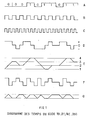
- the diagrams in FIG. 1 show the binary signal carrying the information to be transmitted in A respectively, in B the clock signal defining the rhythm of the binary signal, in C the clock signal defining the rhythm of the signal transcoded; this signal C is at double frequency of the signal B.
- the diagram D represents the transcoded signal corresponding to the information A using the alphabet of table 1 and an internal logic of the coder explained below. As it appears, each of the binary symbols of the information can be associated with a ternary word of two symbols chosen from four possible words.
- the diagram F is deduced from the diagram D by changing the sign of the second symbol of each ternary word and makes it possible to calculate the alternating sum.
- the choice of the alphabet is made according to the value of the signal E at the end of the ternary word, according to the law in Table 2.
- the internal states of the encoder are none other than the conventional representation of the pairs of possible values of the curves E and G at the end of the transcoded word.
- the multiplier of error for this code is 0.59.
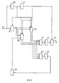
- FIG. 2 is a block diagram of the coder used in the previous example.
- the input of the coder to which the binary information to be transmitted is applied is represented in EB.
- Diagram A of FIG. 1 is shown in ST.
- the output terminal on which the ternary signal intended for transmission on the line is delivered is shown in ST. diagram D).
- 10 shows a clock reproducing the rhythm frequency of the binary input information. This clock can be synchronized by the signal itself, as represented by the broken line 9, or by any other external means.
- the clock 10 delivers the signal represented by the diagram B in FIG. 1; it feeds a binary multiplier 11 ensuring a multiplication by two.
- the output signal of the multiplier 11 corresponds to diagram C of FIG. 1.
- the input signal is applied in parallel to one of the terminals of each of two address generator circuits, respectively 12 and 13, associated respectively with read-only memories 14 and 15.
- memory 14 are stored the permitted code words of the alphabets as defined in table 1.
- the selected code word is transmitted via parallel-series registers 16 and 17 and a summing circuit 20 at the output ST.
- the registers 16 and 17 are synchronized respectively by the clock 10 and the circuit 11 for recording and reading.
- These signals control the choice of the code word used from the four alphabets defined in Table 1, taking into account the code word which has just been transmitted, so that the condition B + B 's 4 to which the code obeys is respected . It constitutes what has been designated above by “internal logic of the coder. This internal logic is defined by Tables 2 and 3.
- FIG. 3 is a block diagram of the decoder corresponding to the coder of FIG. 2.
- the input of the decoder connected to the transmission line, receiving the transmitted ternary signal, has been shown at AND.
- the rhythm frequency of this signal is reconstituted in the clock 30 which supplies on the one hand a regenerator 31 and, on the other hand, a frequency divider circuit 21 restoring the rhythm of the binary information.
- the regenerator 31 includes in particular, as is well known, circuits equalization and amplification of the received signal. Its implementation is not modified by the coding method according to the invention.
- the amplified ternary signal is applied to registers 26 and 27 series-parallel, synchronized by the circuit 21 and the clock 30 so as to restore the division into ternary words of two symbols.
- the memory 24 delivers (output SB) the binary information corresponding to the word applied to the generator 22, by l 'through a shaping circuit 29 synchronized by the clock 21, this shaping being done by sampling.
- the address generator 23 supplies the read-only memory 25 for recognizing prohibited words which, via the synchronization circuit 28, controls the registers 26 and 27. In fact, words comprising two symbols are cut out in the continuous ternary sequence transmitted by line; the output information from registers 26 and 27 is a ternary word of two symbols which can either belong to two successive words, or to the same word.
- the words formed correspond to forbidden words which, via the elements 23 and 25, control the synchronization circuit of the registers 26 and 27, advancing the registers by an elementary time.
- the words reconstituted by the registers belong to an alphabet of the code and correspond to binary information transmitted by the set 22, 24 and 29 at the output SB. It is obvious that the increase in the number of prohibited words facilitates synchronization.
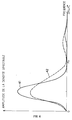
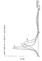
- FIG. 4 represents the spectral densities, that is to say the amplitude responses for a binary train of constant amplitude, on the one hand of the code which has just been defined (solid line 41) and for the purposes of comparison, the frequency spectrum of the AMI (Alternate Mark Inversion) code (broken line 42).
- AMI Alternate Mark Inversion
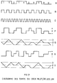
- the binary sequence A corresponds to the code represented by the diagram H.
- the diagrams B and C respectively represent the rhythms of the binary and ternary signals.
- Diagram H represents the coded signal, the diagram I the integral of H.
- the diagram J is derived from the diagram H by inverting the second symbol of each ternary word and the diagram K is the integral of the diagram J.
- FIGS. 6 and 7 respectively represent the same variables for two other codes according to the invention, the code 1 B / 2T 4E 2S2 3M, differing from the previous one by the number of forbidden words which becomes three instead of one, and the code 1 B / 2T 4E 2S2 2M in which the number of prohibited words is two.
- the invention is more generally applicable to codes of the nB / mT type, n and m being any integers.
- the invention is not limited to transcoding from binary to ternary, but also applies to binary-binary transcoding, of the so-called nB / mB type.
- a code of the type 3B / 4B called 3B / 4B 4E 6S6 OM, comprising four alphabets is described below, for which the maximum variation of the numerical sum (B) and of the alternating sum (B ') is equal to 6, and having no prohibited word, which gives a better performance for the code but complicates the decoding, as is known.
- the conversion table is reproduced in table 7 for coding and table 2 for decoding.
- the internal logic of the coder is defined by the last right column of table 7 which fixes the rank of the alphabet to be used for coding the next word.
- the signs + and - appearing in these tables corresponding to the values 1 and 0 assigned to the two binary symbols.
- FIG. 9 show, respectively at A the binary input signal, at B the clock signal defining the rhythm of the input bit stream, at C the clock signal defining the rhythm of the flow transcoded, which is at 4/3 frequency of signal B.
- Diagram D represents a synchronization signal common to clocks B and C.
- Diagram P represents the coded signal corresponding to information A using the alphabets of table 7 and the internal logic of the encoder explained in the last column on the right. As it appears, each of the eight binary words of three symbols of the bit stream to be coded is associated with a binary word of four symbols chosen from four possible alphabets. The choice of the alphabet used is made, from the code word previously used, to take account of the conditions imposed on the variations of the numerical sum and of the alternating sum.
- Diagram Q integral of diagram P
- B 6
- the diagram R is deduced from the diagram P by changing the sign of the second symbol of each transcoded word and makes it possible to calculate the alternating sum.
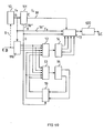
- FIG. 10 is a block diagram of the coder similar to that of FIG. 2 but adapted to the example above.
- the input of the coder to which the input bit stream to be transcoded is shown in EB is represented (diagram A in FIG. 9) and in SC the output terminal on which the bit stream transcoded at 4/3 rhythm is delivered the rate of the input bit stream, intended for transmission on the line (diagram P).
- the clock representing the rhythm frequency of the input bit stream is shown at 10. This clock can be synchronized by the signal itself, as represented by the broken line 9, or by any other external means.
- the clock 10 delivers the signal represented by the diagram B in FIG. 9. This signal is transmitted by the conductor 18 ′ to the parallel-series register 17 as well as to a series-parallel register 116.
- the clock 10 supplies a multiplier binary 111 ensuring a multiplication by 4/3.
- the output signal of the multiplier 111, transmitted by the conductor 18 to the register 17, corresponds to diagram C of FIG. 9.
- the multiplier 111 delivers by a conductor 18 "a signal for splitting the input bit stream EB into words of three symbols (diagram D in FIG. 9).
- This word cutting or synchronization signal is applied to the register 17.
- the word synchronization signal is also applied to the delay circuit 19.
- the input stream EB is transformed, in the serial-parallel register 116 supplying in parallel the two address generating circuits, respectively 12 and 13, associated respectively with the read-only memories 14 and 15 in a series of words of three symbols.
- In the memory 14 are stored the alphabets of code words as defined for example in table 7.
- the selected code word is transmitted via the parallel-series register 17 and a shaping circuit 120 to the output SC.
- the memory 15 are recorded the signs to those of the address generators 12 and 13 applied to them via the delay circuit 19 introducing a delay equal to the duration of a code word.
- These circuits ensure the selection of the alphabet according to the law appearing in the last right column of table 7 and constitute the "internal logic of the coder.
- the circuit 19 receives the word synchronization signal (D FIG. 9) to respect the phasing of the chopping.
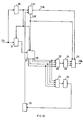
- FIG. 11 is a block diagram of the decoder similar to that of FIG. 3 but corresponding to the coder of FIG. 10.
- the input of the decoder, connected to the transmission line receiving the transcoded bit stream, has been shown in EC.
- the rhythm frequency of this line signal is reconstituted in the clock 30 which supplies on the one hand the regenerator 31 and, on the other hand, a frequency divider circuit by 3/4, 121, restoring the rhythm of the bit stream on the output feeding a conductor 126 and the rhythm of the words 1/4 of the line rhythm) on the output feeding a conductor 126 '.
- the regenerator 31 notably includes circuits for equalizing and amplifying the line signal.
- the regenerated transcoded bit stream is applied to the serial-parallel register 27 synchronized by the elements 121 and 30 so as to reconstruct the code words of four symbols.
- code words are applied to the two address generators 22 and 23 associated with the two read-only memories 24 and 25.
- the memory 24 delivers to the output SB the binary word of three symbols corresponding to the code word applied at 22, according to the correspondence appearing for example in Table 8, by means of a shaping circuit 29 synchronized by the clock 21 of the bit stream rhythm, this shaping being done by sampling.
- the address generator 23 supplies the memory 25 for decoding information necessary for the recovery of synchronization of the words of the code: phasing of the division of the transmitted stream into words of four symbols. It is provided by the delay circuit 28 which controls the circuit 21 and more particularly the signal appearing on 26 '. Indeed, the online bit stream is continuous.
- the associated symbols can either belong to two successive words, or to the same word (phasing of the division into words of the transmitted bit stream).
- certain words formed correspond to forbidden words which, via 23 and 25, control the circuit 28 synchronizing the register 27, making the register advance by an elementary time by the clock 21.
- the words reconstituted by the register all belong to an alphabet of the code and correspond to a binary word decoded with three symbols transmitted by the set 22, 24 and 29 at the output SB. It is obvious that the increase in the number of prohibited words facilitates synchronization.
- the phasing of the division into words of four symbols is carried out by reconstitution in the synchronization member 28 of the internal states of the coder of FIG. 10.
- the signal leaving 25 then indicates the sum current of the received word; 28 thus controls the current and alternating sums of the flux received, at the instants of phasing, and ensures that the limits B and B 'are not exceeded.
- FIG. 12 represents at 141 the distribution of the spectral density of the code defined by Tables 7 and 8.
- the abscissa axis is graduated in normalized frequency (relation to the binary rhythm of the signal to be coded).
- the spectral density corresponding to code 5B-6B used in particular in transmission over optical fiber has been shown at 142.
- the figure clearly shows the advantages of the code according to the invention: higher density between 0 and 2/3 - zero energy at 2/3, 4/3, etc. while the first zero of the code 5B-6B is at 6/5.
- Examination of curve 141 shows that the bandwidth allocated to the transmission of the coded signals according to the invention can, despite the increase in the rate, be limited to the standardized frequency band 0-2 / 3. Under these conditions, an error on the bit stream of the line causes on average 1.443 error on the decoded bit stream.
- This code has maximum performance since all the words in the code are used.
- the curves correspond to an equiprobability of the two symbols in the stream to be coded. If we vary the probability of the binary symbols at the input of the coder, we notice that the spectrum of the code varies little. The code is therefore only very insensitive to the distribution of the bit stream and the economy of a jamming member is possible in equipment where this code is used.
- the frequency spectrum of the codes according to the invention does not have a continuous component. It also has a concentration of energy between the frequency zero and the first zero following, a concentration before two thirds of the input binary frequency, which is an advantage over previous binary codes, even the most economical in width of tape.
- the frequency spectrum of the preferred code variants according to the invention is relatively insensitive to the distribution of binary symbols in the information to be transmitted.
Landscapes
- Physics & Mathematics (AREA)
- Spectroscopy & Molecular Physics (AREA)
- Engineering & Computer Science (AREA)
- Computer Networks & Wireless Communication (AREA)
- Signal Processing (AREA)
- Compression, Expansion, Code Conversion, And Decoders (AREA)
- Dc Digital Transmission (AREA)
Description
La présente invention se rapporte au domaine du transcodage d'informations et elle a plus particulièrement pour objet un procédé de transformation d'un flux d'informations, binaires par exemple, en un flux d'impulsions mieux adapté aux milieux de transmission usuels (câble à conducteur métallique, câble à fibres optiques, etc.).The present invention relates to the field of information transcoding and it relates more particularly to a method of transforming a flow of information, binary for example, into a pulse flow better suited to the usual transmission media (cable with metallic conductor, fiber optic cable, etc.).
L'invention a également pour objet un système de transmission permettant la mise en oeuvre de ce procédé.The invention also relates to a transmission system allowing the implementation of this method.
Le problème posé par un tel transcodage a fait l'objet de nombreuses études, parmi lesquelles on peut citer à titre d'exemple l'article de J. VALIN, paru dans la revue technique THOMSON-CSF, (volume Il n° 2 juin 1979 page 359) ; il en ressort notamment que les caractéristiques recherchées pour un code sont: la minimisation de la bande passante normalement nécessaire pour transmettre correctement le signal ; la suppression de la composante continue, de façon à permettre la simplification de certains éléments du système de transmission ; la possibilité de disposer d'un processus autosynchronisant, permettant d'éviter l'adjonction d'un canal particulier pour la transmission de signaux de synchronisation, et la détection intrinsèque des erreurs de transmission. On connaît en particulier un certain nombre de codes complexes, décrits notamment dans l'article précité, tels que les codes ternaires, quaternaires, etc., pour lesquels le nombre de combinaisons possibles est supérieur à celui du code, par exemple binaire, de départ. Cette redondance permet de définir plusieurs alphabets, c'est-à-dire qu'à chaque valeur possible du code de départ il correspond plusieurs valeurs du code complexe.The problem posed by such a transcoding has been the subject of numerous studies, among which we can cite as an example the article by J. VALIN, published in the technical journal THOMSON-CSF, (volume Il n ° 2 June 1979 page 359); it emerges in particular that the characteristics sought for a code are: the minimization of the bandwidth normally necessary to correctly transmit the signal; the elimination of the continuous component, so as to allow the simplification of certain elements of the transmission system; the possibility of having a self-synchronizing process, making it possible to avoid the addition of a particular channel for the transmission of synchronization signals, and the intrinsic detection of transmission errors. We know in particular a certain number of complex codes, described in particular in the aforementioned article, such as ternary, quaternary codes, etc., for which the number of possible combinations is greater than that of the starting code, for example binary . This redundancy makes it possible to define several alphabets, that is to say that each possible value of the starting code corresponds to several values of the complex code.
On appelle loi de codage la loi permettant de choisir pour chaque valeur du code de départ celui des alphabets qui sera utilisé, en fonction des critères qui tiennent compte de l'ensemble du message déjà transmis : ce critère est la somme numérique courante, dont on rappelle qu'elle est la somme des valeurs des symboles du code entre l'instant choisi comme origine de l'émission et un instant quelconque. Or, il est connu que le bornage de la somme numérique permet notamment d'éliminer la composante continue du signal transmis : la loi de codage règle donc en général le passage d'un alphabet à l'autre en vue de diminuer la somme numérique courante.We call coding law the law allowing to choose for each value of the starting code that of the alphabets which will be used, according to criteria which take into account the whole of the message already transmitted: this criterion is the current numerical sum, of which recalls that it is the sum of the values of the symbols of the code between the instant chosen as the origin of the emission and any instant. However, it is known that the bounding of the digital sum makes it possible in particular to eliminate the continuous component of the transmitted signal: the coding law therefore generally regulates the passage from one alphabet to another in order to reduce the current digital sum .
La présente invention a pour but la réduction de la largeur du spectre de fréquence utilisé pour la transmission des informations par rapport à celle des codes usuels. Cela est réalisé par le bornage de la somme alternée, c'est-à-dire la somme des valeurs des symboles de rang pair diminuée de la somme des symboles de rang impair d'un même code, entre l'instant choisi comme origine de l'émission et un instant quelconque.The present invention aims to reduce the width of the frequency spectrum used for the transmission of information compared to that of the usual codes. This is achieved by delimiting the alternating sum, i.e. the sum of the values of the symbols of even rank minus the sum of the symbols of odd rank of the same code, between the instant chosen as the origin of the broadcast and any moment.
A cet effet, l'invention a pour objet un procédé de transcodage d'une information exprimée selon un premier code, à transmettre sur une voie de transmission selon un second code, et comportant les phases suivantes :
au codage
- - récupération du rythme de l'information exprimée selon le premier code ;
- - élaboration d'un rythme correspondant au second code, dit « rythme de code" ;
- - transformation du premier codage en second codage par le choix d'un parmi plusieurs alphabets susceptibles d'assurer une telle transformation, ce choix étant effectué en fonction de la valeur de la somme numérique et de la valeur de la somme alternée, qui doivent rester bornées ;
- - émission à une extrémité de la voie de transmission de l'information exprimée selon le second codage, au rythme de code ;
au décodage - - récupération du rythme de code à partir de l'information reçue ;
- - élaboration du rythme correspondant au premier code ;
- - découpage de l'information reçue en mots constitués d'un nombre prédéfini de symboles
- - comparaison de ces mots avec un ensemble prédéfini de mots interdits ;
- - mise en phase dudit découpage à partir de la comparaison précédente ;
- - transformation du second codage en premier codage.
coding
- - recovery of the rhythm of the information expressed according to the first code;
- - development of a rhythm corresponding to the second code, called "code rhythm";
- - transformation of the first coding into second coding by the choice of one among several alphabets capable of ensuring such a transformation, this choice being made according to the value of the digital sum and the value of the alternating sum, which must remain bounded;
- - Transmission at one end of the transmission channel of the information expressed according to the second coding, at the code rate;
decoding - - recovery of the code rhythm from the information received;
- - elaboration of the rhythm corresponding to the first code;
- - division of the information received into words made up of a predefined number of symbols
- - comparison of these words with a predefined set of prohibited words;
- - phasing of said division from the previous comparison;
- - transformation of the second coding into the first coding.
L'invention a également pour objet un système de transmission d'informations permettant la mise en oeuvre du procédé ci-dessus et comporte à cet effet un module d'émission et un module de réception placés de part et d'autre d'une ligne de transmission.The invention also relates to an information transmission system allowing the implementation of the above method and for this purpose comprises a transmission module and a reception module placed on either side of a line. of transmission.
D'autres objets, caractéristiques et résultats de l'invention ressortiront de la description suivante, donnée à titre d'exemple non limitatif et illustrée par les dessins annexés, où :
- la figure 1 est un diagramme des temps d'un premier transcodage selon l'invention ;
- les figures 2 et 3 sont des schémas d'un mode de réalisation d'un codeur et d'un décodeur correspondant à l'exemple de la figure 1 ;
- la figure 4 est un diagramme de comparaison des densités spectrales du code de la figure 1 et du code AMI ;
- les figures 5, 6 et 7 sont des diagrammes des temps de trois autres transcodages selon l'invention ;
- la figure 8 est un diagramme des densités spectrales des trois codes des figures 5, 6 et 7 ;
- la figure 9 est un diagramme des temps d'un cinquième transcodage selon l'invention ;
- les figures 10 et 11 sont des schémas d'un mode de réalisation d'un codeur et d'un décodeur correspondant à l'exemple de la figure 9 ;
- la figure 12 est un diagramme de comparaison du code de la figure 9 et d'un code connu.
- FIG. 1 is a time diagram of a first transcoding according to the invention;
- Figures 2 and 3 are diagrams of an embodiment of an encoder and a decoder corresponding to the example of Figure 1;
- FIG. 4 is a diagram for comparing the spectral densities of the code of FIG. 1 and of the AMI code;
- Figures 5, 6 and 7 are timing diagrams of three other transcodings according to the invention;
- FIG. 8 is a diagram of the spectral densities of the three codes of FIGS. 5, 6 and 7;
- FIG. 9 is a time diagram of a fifth transcoding according to the invention;
- Figures 10 and 11 are diagrams of an embodiment of an encoder and a decoder corresponding to the example of Figure 9;
- Figure 12 is a diagram comparing the code of Figure 9 and a known code.
La première mise en oeuvre de l'invention utilise un transcodage particulier du type dit 1 B/2T, dans lequel l'information à transmettre est exprimée sous forme binaire et l'information transcodée, émise sur la voie de transmission, est exprimée sous forme de mots de deux symboles ternaires, c'est-à-dire pouvant prendre une parmi trois valeurs, représentées habituellement par les symboles : « O » « + » et «―»The first implementation of the invention uses a particular transcoding of the so-called 1 B / 2T type, in which the information to be transmitted is expressed in binary form and the transcoded information, transmitted on the transmission channel, is expressed in form of words of two ternary symbols, that is to say can take one of three values, usually represented by the symbols: "O" "+" and "-"
Le tableau ci-dessous donne un exemple d'un tel codage à quatre alphabets, c'est-à-dire que pour chaque bit, la correspondance se fait en prenant un parmi quatre mots ternaires de deux caractères, selon les critères suivants :
- - la variation maximale de la somme courante (notée B) doit être égale à 3 ;
- - la variation maximale de la somme alternée (notée B') doit être égale à 1, ce qui donne B+B'≤4;
- - le nombre de mots interdits est de trois.

- - the maximum variation of the current sum (noted B) must be equal to 3;
- - the maximum variation of the alternating sum (noted B ') must be equal to 1, which gives B + B'≤4;
- - the number of prohibited words is three.
Ce code est dit 1 B/2T 4E 3S1 3M, où 3 et 1 sont les bornes des variations des sommes courante et alternée et 3M signifie qu'il comporte trois mots interdits.This code is called 1 B /
On a représenté sur les diagrammes de la figure 1, respectivement en A le signal binaire portant l'information à transmettre, en B le signal d'horloge définissant le rythme du signal binaire, en C le signal d'horloge définissant le rythme du signal transcodé ; ce signal C est à fréquence double du signal B. Le diagramme D resprésente le signal transcodé correspondant à l'information A en utilisant l'alphabet du tableau 1 et une logique interne du codeur explicitée plus loin. Ainsi qu'il apparaît, chacun des symboles binaires de l'information peut être associé à un mot ternaire de deux symboles choisi parmi quatre mots possibles. Le diagramme E, intégrale du diagramme D, représente les variations de la somme numérique. Elle est limitée à 3 = B. Le diagramme F se déduit du diagramme D en changeant le signe du deuxième symbole de chaque mot ternaire et permet de calculer la somme alternée. Le diagramme G, intégrale du diagramme F, représente les variations de la somme alternée. Le diagramme G est limité à 1 = B'.The diagrams in FIG. 1 show the binary signal carrying the information to be transmitted in A respectively, in B the clock signal defining the rhythm of the binary signal, in C the clock signal defining the rhythm of the signal transcoded; this signal C is at double frequency of the signal B. The diagram D represents the transcoded signal corresponding to the information A using the alphabet of table 1 and an internal logic of the coder explained below. As it appears, each of the binary symbols of the information can be associated with a ternary word of two symbols chosen from four possible words. Diagram E, integral of diagram D, represents the variations of the numerical sum. It is limited to 3 = B. The diagram F is deduced from the diagram D by changing the sign of the second symbol of each ternary word and makes it possible to calculate the alternating sum. Diagram G, integral of diagram F, represents the variations of the alternating sum. Diagram G is limited to 1 = B '.
Dans cet exemple, le choix de l'alphabet est effectué d'après la valeur du signal E en fin de mot ternaire, suivant la loi du tableau 2.

En fin de mot, la valeur de E détermine en effet celle de G de la manière suivante :

D'une manière plus générale, les états internes du codeur ne sont autres que la représentation conventionnelle des couples de valeurs possibles des courbes E et G en fin de mot transcodé. Le coefficient multiplicatif d'erreur de ce code est 0,59.More generally, the internal states of the encoder are none other than the conventional representation of the pairs of possible values of the curves E and G at the end of the transcoded word. The multiplier of error for this code is 0.59.
La figure 2 est un bloc diagramme du codeur utilisé dans l'exemple précédent.FIG. 2 is a block diagram of the coder used in the previous example.
On a représenté en EB l'entrée du codeur à laquelle est appliquée l'information binaire à transmettre (diagramme A de la figure 1) et en ST la borne de sortie sur laquelle est délivré le signal ternaire destiné à la transmission sur la ligne (diagramme D). On a représenté en 10 une horloge restituant la fréquence de rythme de l'information binaire d'entrée. Cette horloge peut être synchronisée par le signal lui-même, ainsi qu'il est représenté par la ligne interrompue 9, ou par tout autre moyen extérieur. L'horloge 10 délivre le signal représenté par le diagramme B de la figure 1 ; elle alimente un multiplicateur binaire 11 assurant une multiplication par deux. Le signal de sortie du multiplicateur 11 correspond au diagramme C de la figure 1. Le signal d'entrée est appliqué en parallèle sur l'une des bornes de chacun de deux circuits générateurs d'adresse, respectivement 12 et 13, associés respectivement à des mémoires mortes 14 et 15. Dans la mémoire 14 sont enregistrés les mots-code permis des alphabets tels que définis sur le tableau 1. Le mot-code sélectionné est transmis par l'intermédiaire de registres parallèle-série 16 et 17 et d'un circuit de sommation 20 à la sortie ST. Ainsi qu'il est représenté par les connexions 18-18', les registres 16 et 17 sont synchronisés respectivement par l'horloge 10 et le circuit 11 à l'enregistrement et à la lecture. Dans la mémoire 15 sont enregistrés les signaux de commande des générateurs d'adresse 12 et 13, appliqués à ceux-ci par l'intermédiaire du circuit à retard 19 qui introduit un retard égal à la durée d'un mot-code. Ces signaux commandent le choix du mot-code utilisé parmi les quatre alphabets définis au tableau 1, compte tenu du mot-code qui vient immédiatement d'être transmis, afin que la condition B + B' s 4 à laquelle obéit le code soit respectée. Elle constitue ce qui a été désigné ci-dessus par « logique interne du codeur. Cette logique interne est définie par les tableaux 2 et 3.The input of the coder to which the binary information to be transmitted is applied is represented in EB. Diagram A of FIG. 1 is shown in ST. The output terminal on which the ternary signal intended for transmission on the line is delivered is shown in ST. diagram D). 10 shows a clock reproducing the rhythm frequency of the binary input information. This clock can be synchronized by the signal itself, as represented by the broken line 9, or by any other external means. The
La figure 3 est un bloc diagramme du décodeur correspondant au codeur de la figure 2.FIG. 3 is a block diagram of the decoder corresponding to the coder of FIG. 2.
On a représenté en ET l'entrée du décodeur reliée à la ligne de transmission, recevant le signal ternaire transmis. La fréquence de rythme de ce signal est reconstituée dans l'horloge 30 qui alimente d'une part un régénérateur 31 et, d'autre part, un circuit diviseur de fréquence 21 restituant le rythme de l'information binaire. Le régénérateur3l comporte notamment, ainsi qu'il est bien connu, des circuits d'égalisation et d'amplification du signal reçu. Sa réalisation n'est pas modifiée par le procédé de codage selon l'invention. Le signal ternaire amplifié est appliqué à des registres 26 et 27 série-parallèle, synchronisés par le circuit 21 et l'horloge 30 de façon à restituer le découpage en mots ternaires de deux symboles. Ces mots sont appliqués à un ensemble de deux générateurs d'adresse, 22 et 23 associés à deux mémoires mortes, respectivement 24 et 25. La mémoire 24 délivre (sortie SB) l'information binaire correspondant au mot appliqué au générateur 22, par l'intermédiaire d'un circuit de mise en forme 29 synchronisé par l'horloge 21, cette mise en forme étant faite par échantillonnage. Le générateur d'adresse 23 alimente la mémoire morte 25 de reconnaissance des mots interdits qui, par l'intermédiaire du circuit de synchronisation 28, commande les registres 26 et 27. En effet, des mots comportant deux symboles sont découpés dans la suite ternaire continue transmise par la ligne ; l'information de sortie des .registres 26 et 27 est un mot ternaire de deux symboles qui peuvent soit appartenir à deux mots successifs, soit au même mot. Dans le premier cas, les mots formés correspondent à des mots interdits qui, par l'intermédiaire des éléments 23 et 25, commandent le circuit de synchronisation des registres 26 et 27, faisant avancer les registres d'un temps élémentaire. Dans le deuxième cas, lorsque le découpage est correct, les mots reconstitués par les registres appartiennent à un alphabet du code et correspondent à une information binaire transmise par l'ensemble 22, 24 et 29 à la sortie SB. Il est bien évident que l'accroissement du nombre de mots interdits facilite la synchronisation.The input of the decoder connected to the transmission line, receiving the transmitted ternary signal, has been shown at AND. The rhythm frequency of this signal is reconstituted in the
La figure 4 représente les densités spectrales, c'est-à-dire les réponses en amplitude pour un train binaire d'amplitude constante, d'une part du code qui vient d'être défini (trait continu 41) et à des fins de comparaison, le spectre de fréquence du code AMI (Alternate Mark Inversion) (trait interrompu 42).FIG. 4 represents the spectral densities, that is to say the amplitude responses for a binary train of constant amplitude, on the one hand of the code which has just been defined (solid line 41) and for the purposes of comparison, the frequency spectrum of the AMI (Alternate Mark Inversion) code (broken line 42).
On a représenté :
- - en Fb la fréquence binaire de l'information et la fréquence de ligne du code AMI ;
- - en FL la fréquence de ligne dans le code de l'invention. On voit que le spectre (41) du code proposé est plus étroit que celui du code AMI, autour de la même fréquence centrale, et donc répond mieux aux conditions posées ci-dessus.
- - at F b the binary frequency of the information and the line frequency of the AMI code;
- - in F L the line frequency in the code of the invention. We see that the spectrum (41) of the proposed code is narrower than that of the AMI code, around the same central frequency, and therefore better meets the conditions set out above.
Les diagrammes de la figure 5 représentent les mêmes variables que les diagrammes de la figure 1 dans le cas d'un deuxième code selon l'invention. Ce code, désigné par 1 B/2T 4 E 2S2 M, se caractérise par :
- - un rythme du code double du rythme binaire ;
- - des mots code ternaires de deux symboles ;
- - quatre alphabets définis
par le tableau 4 ; - - une variation maximale des sommes courante et alternée égale à deux (
diagrammes 1 et K) ; - - un mot interdit.

- - a rhythm of the code double the binary rhythm;
- - ternary code words of two symbols;
- - four alphabets defined by table 4;
- - a maximum variation of the current and alternate sums equal to two (diagrams 1 and K);
- - a prohibited word.
A la suite binaire A correspond le code représenté par le diagramme H. Les diagrammes B et C représentent respectivement les rythmes des signaux binaire et ternaire. Le diagramme H représente le signal codé, le diagramme I l'intégrale de H. Le diagramme J est dérivé du diagramme H en inversant le deuxième symbole de chaque mot ternaire et le diagramme K est l'intégrale du diagramme J.The binary sequence A corresponds to the code represented by the diagram H. The diagrams B and C respectively represent the rhythms of the binary and ternary signals. Diagram H represents the coded signal, the diagram I the integral of H. The diagram J is derived from the diagram H by inverting the second symbol of each ternary word and the diagram K is the integral of the diagram J.
La répartition spectrale de ce code est représentée par la courbe 51 de la figure 8.The spectral distribution of this code is represented by
Les diagrammes des figures 6 et 7 représentent respectivement les mêmes variables pour deux autres codes selon l'invention, le code 1 B/2T 4E 2S2 3M, différant du précédent par le nombre de mots interdits qui devient trois au lieu de un, et le code 1 B/2T 4E 2S2 2M dans lequel le nombre de mots interdits est de deux.The diagrams of FIGS. 6 and 7 respectively represent the same variables for two other codes according to the invention, the code 1 B /
Les alphabets sont représentés respectivement par les tableaux 5 et 6 et les densités spectrales de ces deux codes sont représentées respectivement par les courbes 52 et 53 de la figure 8.


De façon analogue à ce qui a été décrit ci-dessus pour des codes du type 1B/2T, l'invention est applicable plus généralement à des codes de type nB/mT, n et m étant des entiers quelconques.Analogously to what has been described above for codes of the 1B / 2T type, the invention is more generally applicable to codes of the nB / mT type, n and m being any integers.
A titre d'exemple, il a été élaboré un code 3B/4T comportant 4 états internes du codeur, caractérisés chacun par une valeur du couple somme numérique-somme alternée comme indiqué plus haut, avec B = B' = 2. Dans d'autres modes de réalisation, il a été élaboré un code 4B/4T à 6 états internes, avec B = B' = 3, et un code 5B/4T à 8 états internes, avec B = 8 et B' = 5.For example, a 3B / 4T code has been developed comprising 4 internal states of the encoder, each characterized by a value of the digital sum-alternating sum couple as indicated above, with B = B '= 2. In d' other embodiments, a 4B / 4T code with 6 internal states has been developed, with B = B '= 3, and a 5B / 4T code with 8 internal states, with B = 8 and B' = 5.
De façon encore plus générale, l'invention n'est pas limitée au transcodage de binaire en ternaire, mais s'applique également au transcodage binaire-binaire, du type dit nB/mB.Even more generally, the invention is not limited to transcoding from binary to ternary, but also applies to binary-binary transcoding, of the so-called nB / mB type.
A titre d'exemple, on décrit ci-après un code de type 3B/4B, dit 3B/4B 4E 6S6 OM, comportant quatre alphabets, pour lesquels la variation maximale de la somme numérique (B) et de la somme alternée (B') est égale à 6, et ne présentant aucun mot interdit, ce qui donne un meilleur rendement pour le code mais complique le décodage, ainsi qu'il est connu.By way of example, a code of the
La table de conversion est reproduite sur le tableau 7 pour le codage et le tableau 2 pour le décodage. La logique interne du codeur est définie par la dernière colonne de droite du tableau 7 qui fixe le rang de l'alphabet à utiliser au codage du mot suivant. Les signes + et - figurant sur ces tableaux correspondant aux valeurs 1 et 0 affectées aux deux symboles binaires.


On a représenté par les diagrammes de la figure 9, respectivement en A le signal binaire d'entrée, en B le signal d'horloge définissant le rythme du flux binaire d'entrée, en C le signal d'horloge définissant le rythme du flux transcodé, qui est à fréquence 4/3 du signal B. Le diagramme D représente un signal de synchronisation commun aux horloges B et C. Le diagramme P représente le signal codé correspondant à l'information A en utilisant les alphabets du tableau 7 et la logique interne du codeur explicitée sur la dernière colonne de droite. Ainsi qu'il apparaît, chacun des huit mots binaires de trois symboles du flux binaire à coder est associé à un mot binaire de quatre symboles choisi parmi quatre alphabets possibles. Le choix de l'alphabet utilisé est effectué, à partir du mot-code précédemment utilisé, pour tenir compte des conditions imposées aux variations de la somme numériques et de la somme alternée. Ce choix est effectué, par exemple, en sélectionnant le mot code à utiliser par l'adresse de celui-ci dans une mémoire morte grâce à un circuit logique dont la réalisation est à la portée de l'homme de l'art. Le diagramme Q, intégrale du diagramme P, représente les variations de la somme numérique. Elle est limitée à B = 6. Le diagramme R se déduit du diagramme P en changeant le signe du deuxième symbole de chaque mot transcodé et permet de calculer la somme alternée. Le diagramme S, intégrale du diagramme R, représente les variations de la somme alternée. Le diagramme S est limité à 6 = B'.The diagrams in FIG. 9 show, respectively at A the binary input signal, at B the clock signal defining the rhythm of the input bit stream, at C the clock signal defining the rhythm of the flow transcoded, which is at 4/3 frequency of signal B. Diagram D represents a synchronization signal common to clocks B and C. Diagram P represents the coded signal corresponding to information A using the alphabets of table 7 and the internal logic of the encoder explained in the last column on the right. As it appears, each of the eight binary words of three symbols of the bit stream to be coded is associated with a binary word of four symbols chosen from four possible alphabets. The choice of the alphabet used is made, from the code word previously used, to take account of the conditions imposed on the variations of the numerical sum and of the alternating sum. This choice is made, for example, by selecting the code word to be used by the address thereof in a read-only memory by means of a logic circuit the realization of which is within the reach of those skilled in the art. Diagram Q, integral of diagram P, represents the variations of the numerical sum. It is limited to B = 6. The diagram R is deduced from the diagram P by changing the sign of the second symbol of each transcoded word and makes it possible to calculate the alternating sum. Diagram S, integral of diagram R, represents the variations of the alternating sum. The diagram S is limited to 6 = B '.
La figure 10 est un bloc diagramme du codeur analogue à celui de la figure 2 mais adapté à l'exemple ci-dessus.FIG. 10 is a block diagram of the coder similar to that of FIG. 2 but adapted to the example above.
On a représenté en EB l'entrée du codeur à laquelle est appliqué le flux binaire d'entrée à transcoder (diagramme A de la figure 9) et en SC la borne de sortie sur laquelle est délivré le flux binaire transcodé au rythme 4/3 du rythme du flux binaire d'entrée, destiné à la transmission sur la ligne (diagramme P). On a représenté en 10 l'horloge restituant la fréquence de rythme du flux binaire d'entrée. Cette horloge peut être synchronisée par le signal lui-même, ainsi qu'il est représenté par la ligne interrompue 9, ou par tout autre moyen extérieur. L'horloge 10 délivre le signal représenté par le diagramme B de la figure 9. Ce signal est transmis par le conducteur 18' au registre parallèle-série 17 ainsi qu'à un registre série-parallèle 116. L'horloge 10 alimente un multiplicateur binaire 111 assurant une multiplication par 4/3. Le signal de sortie du multiplicateur 111, transmis par le conducteur 18 au registre 17, correspond au diagramme C de la figure 9. Le multiplicateur 111 délivre par un conducteur 18" un signal de découpage du flux binaire d'entrée EB en mots de trois symboles (diagramme D de la figure 9). Ce signal de découpage ou synchronisation de mots est appliqué au registre 17. Le signal de synchronisation de mots est également appliqué au circuit à retard 19. Le flux d'entrée EB est transformé, dans le registre série-parallèle 116 alimentant en parallèle les deux circuits générateurs d'adresse, respectivement 12 et 13, associés respectivement aux mémoires mortes 14 et 15 en une série de mots de trois symboles. Dans la mémoire 14 sont enregistrés les alphabets de mots-code tels que définis par exemple au tableau 7. Le mot-code sélectionné est transmis par l'intermédiaire du registre parallèle-série 17 et d'un circuit de mise en forme 120 à la sortie SC. Dans la mémoire 15 sont enregistrés les signaux de commande des .générateurs d'adresse 12 et 13 appliqués à ceux-ci par l'intermédiaire du circuit à retard 19 introduisant un retard égal à la durée d'un mot-code. Ces signaux commandent le rang de l'alphabet qui doit être utilisé au codage du mot suivant, compte tenu du mot-code qui vient d'être transmis afin que la condition B = 6 et B' = 6 à laquelle obéit le code soit respectée. Ces circuits assurent la sélection de l'alphabet selon la loi figurant à la dernière colonne de droite du tableau 7 et constituent la « logique interne du codeur. Le circuit 19 reçoit le signal de synchronisation de mot (D figure 9) pour respecter la mise en phase du découpage.The input of the coder to which the input bit stream to be transcoded is shown in EB is represented (diagram A in FIG. 9) and in SC the output terminal on which the bit stream transcoded at 4/3 rhythm is delivered the rate of the input bit stream, intended for transmission on the line (diagram P). The clock representing the rhythm frequency of the input bit stream is shown at 10. This clock can be synchronized by the signal itself, as represented by the broken line 9, or by any other external means. The
La figure 11 est un bloc diagramme du décodeur analogue à celui de la figure 3 mais correspondant au codeur de la figure 10.FIG. 11 is a block diagram of the decoder similar to that of FIG. 3 but corresponding to the coder of FIG. 10.
On a représenté en EC l'entrée du décodeur, reliée à la ligne de transmission recevant le flux binaire transcodé. La fréquence de rythme de ce signal de ligne est reconstituée dans l'horloge 30 qui alimente d'une part le régénérateur 31 et, d'autre part, un circuit diviseur de fréquence par 3/4, 121, restituant le rythme du flux binaire sur la sortie alimentant un conducteur 126 et le rythme des mots 1/4 du rythme en ligne) sur la sortie alimentant un conducteur 126'. Le régénérateur 31 comporte notamment des circuits d'égalisation et d'amplification du signal de ligne. Le flux binaire transcodé régénéré est appliqué au .registre 27 série-parallèle synchronisé par les éléments 121 et 30 de façon à reconstituer les mots-code de quatre symboles. Ces mots-code sont appliqués aux deux générateurs d'adresse 22 et 23 associés aux deux mémoires mortes 24 et 25. La mémoire 24 délivre à la sortie SB le mot binaire de trois symboles correspondant au mot-code appliqué en 22, suivant la correspondance figurant par exemple au tableau 8, par l'intermédiaire d'un circuit de mise en forme 29 synchronisé par l'horloge 21 de rythme du flux binaire, cette mise en forme étant faite par échantillonnage. Le générateur d'adresse 23 alimente la mémoire 25 de décodage d'informations nécessaires à la récupération de synchronisation des mots du code : mise en phase du découpage du flux transmis en mots de quatre symboles. Elle est assurée par le circuit à retard 28 qui commande le circuit 21 et plus particulièrement le signal apparaissant sur 26'. En effet, le flux binaire en ligne est continu. Quatre symboles successifs sont associés pour constituer le mot délivré par 27 : les symboles associés peuvent soit appartenir à deux mots successifs, soit au même mot (mise en phase du découpage en mots du flux binaire transmis). Dans le premier cas, certains mots formés correspondent à des mots interdits qui, par l'intermédiaire de 23 et 25, commandent le circuit 28 synchronisant le registre 27, faisant avancer le registre d'un temps élémentaire par l'horloge 21. Dans le deuxième cas, lorsque le découpage est correct, les mots reconstitués par le registre appartiennent tous à un alphabet du code et correspondent à un mot binaire décodé de trois symboles transmis par l'ensemble 22, 24 et 29 à la sortie SB. Il est bien évident que l'accroissement du nombre de mots interdits facilite la synchronisation. En l'absence de mots interdits, la mise en phase du découpage en mots de quatre symboles s'effectue par reconstitution dans l'organe de synchronisation 28 des états internes du codeur de la figure 10. Le signal sortant de 25 indique alors la somme courante du mot reçu ; 28 contrôle ainsi les sommes courante et alternée du flux reçu, aux instants de mise en phase, et fait en sorte que les bornes B et B' ne soient pas dépassées.The input of the decoder, connected to the transmission line receiving the transcoded bit stream, has been shown in EC. The rhythm frequency of this line signal is reconstituted in the
La figure 12 représente en 141 la répartition de la densité spectrale du code défini par les tableaux 7 et 8.FIG. 12 represents at 141 the distribution of the spectral density of the code defined by Tables 7 and 8.
L'axe des abscisses est gradué en fréquence normalisée (rapport au rythme binaire du signal à .coder). A titre de comparaison, on a représenté en 142 la densité spectrale correspondant au code 5B-6B utilisé notamment en transmission sur fibre optique. La figure fait clairement apparaître les avantages du code selon l'invention : densité plus élevée entre 0 et 2/3 - zéro d'énergie à 2/3, 4/3, etc. alors que le premier zéro du code 5B-6B se trouve à 6/5. L'examen de la courbe 141 montre que la largeur de bande allouée à la transmission des signaux codés selon l'invention peut, malgré l'augmentation du rythme, être limitée à la bande de fréquences normalisées 0-2/3. Dans ces conditions, une erreur sur le flux binaire de la ligne provoque en moyenne 1,443 erreur sur le flux binaire décodé. Ce code présente un rendement maximal puisque tous les mots du code sont utilisés. Les courbes correspondent à une équiprobabilité des deux symboles dans le flux à coder. Si on fait varier la probabilité des symboles binaires à l'entrée du codeur, on s'aperçoit que le spectre du code varie peu. Le code n'est donc que très peu sensible à la distribution du flux binaire et l'économie d'un organe de brouillage est possible dans un équipement où ce code est utilisé.The abscissa axis is graduated in normalized frequency (relation to the binary rhythm of the signal to be coded). By way of comparison, the spectral density corresponding to code 5B-6B used in particular in transmission over optical fiber has been shown at 142. The figure clearly shows the advantages of the code according to the invention: higher density between 0 and 2/3 - zero energy at 2/3, 4/3, etc. while the first zero of the code 5B-6B is at 6/5. Examination of
Ainsi qu'il est bien connu, lors de l'égalisation du flux reçu avant décodage, si les fréquences supérieures à la fréquence de ligne (donc ici les 4/3 de la fréquence binaire) sont coupées par un filtre dit de NYQUIST, « centré sur une fréquence dite de NYQUIST, l'intermodulation intersymbole à l'instant d'échantillonnage est nulle. Or les filtres de NYQUIST ne sont pas réalisables et on ne peut que s'en approcher au prix d'une complication croissante du matériel. Dans le cas du codage selon l'invention, le code ne possède que très peu d'énergie autour de cette fréquence de NYQUIST. L'on pourra alors se contenter d'un filtre très simple ne s'approchant que très imparfaitement du filtre théorique de NYQUiST. mais qui n'apportera en fait que peu de dégradation sur le diagramme de l'oeil du signal reçu à l'instant d'échantillonnage, du fait que, comme mentionné plus haut, il n'y a que très peu d'énergie autour de cette fréquence.As is well known, during the equalization of the stream received before decoding, if the frequencies higher than the line frequency (therefore here 4/3 of the binary frequency) are cut by a filter called NYQUIST, " centered on a so-called NYQUIST frequency, the intersymbol intermodulation at the sampling instant is zero. However, NYQUIST filters are not feasible and we can only approach them at the cost of an increasing complication of the material. In the case of coding according to the invention, the code has very little energy around this NYQUIST frequency. We can then be satisfied with a very simple filter approaching only very imperfectly the theoretical filter of NYQUiST. but which will in fact bring little degradation to the eye diagram of the signal received at the sampling instant, because, as mentioned above, there is only very little energy around of this frequency.
De façon analogue à ce qui a été décrit ci-dessus pour le code 3B/4B 4E 6S6 OM, il a été réalisé selon l'invention d'autres codes 3B/4B, tels que le code 3B/4B 4E 8S8 4M, différant du précédent par le nombre de mots interdits (4) et les sommes maximales (B = B' = 8) et le code 3B/4B 4E 8S8 2M, différant du précédent par le nombre de mots interdits.Analogously to what has been described above for the
En conclusion, le spectre de fréquence des codes selon l'invention, comme les codes le plus souvent utilisés, ne présente pas de composante continue. Il présente de plus une concentration de l'énergie entre la fréquence zéro et le premier zéro suivant, une concentration avant deux tiers de la fréquence binaire d'entrée, ce qui est un avantage sur les codes binaires antérieurs, même les plus économiques en largeur de bande. De plus, le spectre de fréquence des variantes préférées de code selon l'invention est relativement insensible à la distribution des symboles binaires dans l'information à transmettre.In conclusion, the frequency spectrum of the codes according to the invention, like the codes most often used, does not have a continuous component. It also has a concentration of energy between the frequency zero and the first zero following, a concentration before two thirds of the input binary frequency, which is an advantage over previous binary codes, even the most economical in width of tape. In addition, the frequency spectrum of the preferred code variants according to the invention is relatively insensitive to the distribution of binary symbols in the information to be transmitted.
Les avantages du transcodage selon l'invention qui peuvent s'ajouter à celui d'une répartition spectrale particulièrement favorable sont notamment les suivants :
- - récupération du rythme facilitée par l'interdiction de suites infinies de symboles consécutifs égaux ;
- - le coefficient multiplicatif d'erreur n'excède pas 1,5 et est inférieur à l'unité pour certaines variantes de l'invention (on rappelle que le coefficient multiplicatif d'erreur est le rapport nombre d'erreurs engendrées sur les mots binaires décodés sur nombre d'erreurs possibles sur les mots-code) ;
- - possibilité de contrôle des erreurs et de détermination du taux d'erreur de la liaison par les méthodes classiques employées à cet effet pour les codes dont le codeur est une machine synchrone séquentielle à nombre fini d'états. Ces méthodes sont notamment décrites dans l'article : « Error détection and synchronization with pseudo-ternary codes for data transmission rédigé par Mssrs. PREPARATA et BELLATO et publié dans la revue « Alta Frequenza Juin 1973, page 280.
- - recovery of the rhythm facilitated by the prohibition of infinite sequences of equal consecutive symbols;
- - the multiplicative error coefficient does not exceed 1.5 and is less than unity for certain variants of the invention (it is recalled that the multiplicative error coefficient is the ratio number of errors generated on binary words decoded on number of possible errors on code words);
- - possibility of error control and determination of the link error rate by the conventional methods used for this purpose for codes whose coder is a synchronous sequential machine with finite number of states. These methods are described in particular in the article: “Error detection and synchronization with pseudo-ternary codes for data transmission written by Mssrs. PREPARATA and BELLATO and published in the review "Alta Frequenza June 1973, page 280.
Claims (12)
during the coding operation
during the decoding operation
Applications Claiming Priority (2)
| Application Number | Priority Date | Filing Date | Title |
|---|---|---|---|
| FR7920063 | 1979-08-06 | ||
| FR7920063A FR2463542A1 (en) | 1979-08-06 | 1979-08-06 | METHOD FOR TERNARY CODING OF BINARY INFORMATION FOR LINE TRANSMISSION AND TRANSMISSION SYSTEM USING THE SAME |
Publications (2)
| Publication Number | Publication Date |
|---|---|
| EP0024236A1 EP0024236A1 (en) | 1981-02-25 |
| EP0024236B1 true EP0024236B1 (en) | 1983-09-14 |
Family
ID=9228641
Family Applications (1)
| Application Number | Title | Priority Date | Filing Date |
|---|---|---|---|
| EP19800401159 Expired EP0024236B1 (en) | 1979-08-06 | 1980-08-06 | Information code conversion method for line transmission and transmission system using such a method |
Country Status (3)
| Country | Link |
|---|---|
| EP (1) | EP0024236B1 (en) |
| DE (1) | DE3064824D1 (en) |
| FR (1) | FR2463542A1 (en) |
Families Citing this family (1)
| Publication number | Priority date | Publication date | Assignee | Title |
|---|---|---|---|---|
| US4486740A (en) * | 1982-12-06 | 1984-12-04 | At&T Bell Laboratories | DC Cancellation in ternary-coded data systems |
Family Cites Families (4)
| Publication number | Priority date | Publication date | Assignee | Title |
|---|---|---|---|---|
| US3215779A (en) * | 1961-02-24 | 1965-11-02 | Hallicrafters Co | Digital data conversion and transmission system |
| US3302193A (en) * | 1964-01-02 | 1967-01-31 | Bell Telephone Labor Inc | Pulse transmission system |
| US3587088A (en) * | 1967-12-21 | 1971-06-22 | Bell Telephone Labor Inc | Multilevel pulse transmission systems employing codes having three or more alphabets |
| GB1539389A (en) * | 1975-12-30 | 1979-01-31 | Standard Telephones Cables Ltd | Data transmission |
-
1979
- 1979-08-06 FR FR7920063A patent/FR2463542A1/en active Granted
-
1980
- 1980-08-06 EP EP19800401159 patent/EP0024236B1/en not_active Expired
- 1980-08-06 DE DE8080401159T patent/DE3064824D1/en not_active Expired
Also Published As
| Publication number | Publication date |
|---|---|
| DE3064824D1 (en) | 1983-10-20 |
| EP0024236A1 (en) | 1981-02-25 |
| FR2463542A1 (en) | 1981-02-20 |
| FR2463542B1 (en) | 1983-10-07 |
Similar Documents
| Publication | Publication Date | Title |
|---|---|---|
| FR2471109A1 (en) | DIGITAL MAGNETOSCOPE | |
| EP0481549B1 (en) | Coding/decoding system and method for digital signals transmitted by coded modulation | |
| FR2559935A1 (en) | INFORMATION RECORDING AND / OR READING METHOD FOR OPTICAL INFORMATION MEDIUM, DEVICE FOR IMPLEMENTING SAID METHOD, AND INFORMATION CARRIER REALIZED FOR IMPLEMENTING THE METHOD | |
| EP1677422A1 (en) | Apparatus for conversion of a transmitted signal into a binary signal | |
| EP0053958B1 (en) | Process for the parallel/series conversion of a digital parallel sequence | |
| EP0026699B1 (en) | Method and device for coding digital data, device for decoding digital data and a transmission system comprising such a device | |
| EP0141721A2 (en) | Receiving device in a transmission system for asynchronous video information | |
| EP0188030B1 (en) | Method of coding and decoding of audio information and apparatus for carrying out the method | |
| EP0024236B1 (en) | Information code conversion method for line transmission and transmission system using such a method | |
| EP0228528A1 (en) | Apparatus for implementing a code with a small digital sum variation in a fast digital transmission, and coding method using such an apparatus | |
| EP0083998B1 (en) | Scramble or unscramble byte generator | |
| EP0629059A1 (en) | Spread spectrum digital transmission system with low frequency pseudorandom coding of the useful information and method for spectrum spreading and compressing used in such a system | |
| FR2522908A1 (en) | Modification system for information on service channel - uses coding and logic gating circuit to inject data onto transmission channel | |
| EP0229738B1 (en) | Method and device for the regeneration of the integrity of the binary throughput in a pleisiochronous network | |
| EP0196979A1 (en) | Method and device for inserting a digital signal into a higher rate channel | |
| EP0045680A1 (en) | Method of transcoding information, and transmission system using such a method | |
| FR2765757A1 (en) | METHOD AND DEVICE FOR MODULATING A MULTI-PORTER SIGNAL OF THE OFDM / OQAM TYPE, AND CORRESPONDING METHOD AND DEVICE FOR DEMODULATION | |
| FR2613893A1 (en) | METHOD FOR SWITCHING ASYNCHRONOUS DIGITAL SIGNALS, AND DEVICE FOR IMPLEMENTING SAID METHOD | |
| FR2472310A1 (en) | Transcoding of binary information for line transmission - by converting input binary code into code at four thirds input frequency for reduced spectrum | |
| FR2585203A1 (en) | SYSTEM FOR REDUCING FREQUENCY OF DIGITAL SAMPLES | |
| FR2800951A1 (en) | ESTIMATING THE OPTIMUM SAMPLING INSTANT IN A TDMA PACKET TRANSMISSION SYSTEM | |
| EP0009557B1 (en) | Method and circuit for the simultaneous coding of two binary signal sequences into one pulse sequence, method and circuit for decoding the latter sequence, and their application to an interface transmitter-receiver | |
| FR2798025A1 (en) | Receiver for decoding serial data signal, has receiving section, delay circuit, multiplier circuit and detection circuit for detecting synchronization and information signals. | |
| EP0086441B1 (en) | Quadriphase coding arrangements for synchronous data transmission | |
| FR2549322A1 (en) | Method of shaping a digital signal by sampling, and corresponding device. |
Legal Events
| Date | Code | Title | Description |
|---|---|---|---|
| PUAI | Public reference made under article 153(3) epc to a published international application that has entered the european phase |
Free format text: ORIGINAL CODE: 0009012 |
|
| AK | Designated contracting states |
Designated state(s): CH DE GB NL SE |
|
| 17P | Request for examination filed |
Effective date: 19810317 |
|
| GRAA | (expected) grant |
Free format text: ORIGINAL CODE: 0009210 |
|
| AK | Designated contracting states |
Designated state(s): CH DE GB LI NL SE |
|
| REF | Corresponds to: |
Ref document number: 3064824 Country of ref document: DE Date of ref document: 19831020 |
|
| PLBE | No opposition filed within time limit |
Free format text: ORIGINAL CODE: 0009261 |
|
| STAA | Information on the status of an ep patent application or granted ep patent |
Free format text: STATUS: NO OPPOSITION FILED WITHIN TIME LIMIT |
|
| 26N | No opposition filed | ||
| PGFP | Annual fee paid to national office [announced via postgrant information from national office to epo] |
Ref country code: DE Payment date: 19940526 Year of fee payment: 15 |
|
| PGFP | Annual fee paid to national office [announced via postgrant information from national office to epo] |
Ref country code: SE Payment date: 19940527 Year of fee payment: 15 Ref country code: CH Payment date: 19940527 Year of fee payment: 15 |
|
| PGFP | Annual fee paid to national office [announced via postgrant information from national office to epo] |
Ref country code: GB Payment date: 19940531 Year of fee payment: 15 |
|
| PGFP | Annual fee paid to national office [announced via postgrant information from national office to epo] |
Ref country code: NL Payment date: 19940831 Year of fee payment: 15 |
|
| EAL | Se: european patent in force in sweden |
Ref document number: 80401159.1 |
|
| PG25 | Lapsed in a contracting state [announced via postgrant information from national office to epo] |
Ref country code: GB Effective date: 19950806 |
|
| PG25 | Lapsed in a contracting state [announced via postgrant information from national office to epo] |
Ref country code: SE Effective date: 19950807 |
|
| PG25 | Lapsed in a contracting state [announced via postgrant information from national office to epo] |
Ref country code: LI Effective date: 19950831 Ref country code: CH Effective date: 19950831 |
|
| PG25 | Lapsed in a contracting state [announced via postgrant information from national office to epo] |
Ref country code: NL Effective date: 19960301 |
|
| GBPC | Gb: european patent ceased through non-payment of renewal fee |
Effective date: 19950806 |
|
| REG | Reference to a national code |
Ref country code: CH Ref legal event code: PL |
|
| NLV4 | Nl: lapsed or anulled due to non-payment of the annual fee |
Effective date: 19960301 |
|
| PG25 | Lapsed in a contracting state [announced via postgrant information from national office to epo] |
Ref country code: DE Effective date: 19960501 |
|
| EUG | Se: european patent has lapsed |
Ref document number: 80401159.1 |