EP0023977A1 - Storage device for articles, particularly recording-tape cassettes - Google Patents
Storage device for articles, particularly recording-tape cassettes Download PDFInfo
- Publication number
- EP0023977A1 EP0023977A1 EP80104043A EP80104043A EP0023977A1 EP 0023977 A1 EP0023977 A1 EP 0023977A1 EP 80104043 A EP80104043 A EP 80104043A EP 80104043 A EP80104043 A EP 80104043A EP 0023977 A1 EP0023977 A1 EP 0023977A1
- Authority
- EP
- European Patent Office
- Prior art keywords
- receiving compartments
- container
- tilting
- objects
- compartments
- Prior art date
- Legal status (The legal status is an assumption and is not a legal conclusion. Google has not performed a legal analysis and makes no representation as to the accuracy of the status listed.)
- Withdrawn
Links
- 230000002093 peripheral effect Effects 0.000 claims description 3
- 230000001154 acute effect Effects 0.000 claims description 2
- 230000000284 resting effect Effects 0.000 claims 1
- 230000002349 favourable effect Effects 0.000 abstract 1
- 238000010276 construction Methods 0.000 description 5
- 238000005192 partition Methods 0.000 description 2
- 230000006835 compression Effects 0.000 description 1
- 238000007906 compression Methods 0.000 description 1
- 239000006071 cream Substances 0.000 description 1
- 230000001681 protective effect Effects 0.000 description 1
Images
Classifications
-
- G—PHYSICS
- G11—INFORMATION STORAGE
- G11B—INFORMATION STORAGE BASED ON RELATIVE MOVEMENT BETWEEN RECORD CARRIER AND TRANSDUCER
- G11B23/00—Record carriers not specific to the method of recording or reproducing; Accessories, e.g. containers, specially adapted for co-operation with the recording or reproducing apparatus ; Intermediate mediums; Apparatus or processes specially adapted for their manufacture
- G11B23/02—Containers; Storing means both adapted to cooperate with the recording or reproducing means
- G11B23/023—Containers for magazines or cassettes
- G11B23/0236—Containers for several cassettes
Definitions
- the invention relates to a device for storing essentially rectangular objects, in particular cassettes with a tape-shaped recording medium, with a plurality of receiving compartments for the objects delimited by at least two side walls and a base.
- Devices for storing magnetic tape cassettes within reach are known whose cream compartments only have two side walls, a rear wall and a bottom (cf. DE-GM 75 2562 6; CH-PS 5 82 935).
- the cassette corner edges are aligned with one another, so that they must be grasped on their upstanding long sides and removed from the receiving compartments for their removal.
- These devices are not to be designed as lockable structures
- a device is also known in which the receiving compartments are located within a receiving housing. Each receiving compartment contains a slide for receiving a cassette, which at the same time closes the relevant receiving compartment when inserted. (DE-OS 25 56 609).
- the slides in the housing must be unlocked, after which they are automatically pushed out of the storage compartment by a compression spring.
- An unlocking device is therefore provided for each receiving compartment, it being possible for only one cassette to be inserted into or removed from the receiving housing at a time.
- the object on which the invention is based is now to create a device for storing rectangular objects, in particular cassettes with a tape-shaped recording medium, the construction principle of which enables stored objects to be transferred into a position which allows them to be advantageously removed from the device, This applies both when the device is equipped with freely accessible receptacles lying next to one another and also with receptacles accommodated in an optionally lockable housing.
- the bottom of the receiving compartments has at least one edge extending transversely to its longitudinal direction for tipping over the objects placed in the receiving compartments.
- the arrangement of a tilting edge on the bottom of the receiving compartments allows stored objects in the receiving compartments to be tipped over, so that they can be inclined relative to the adjacent objects, or can be displaced in such a way that two corner pieces thereof from the group of the same position in the device Objects and can be gripped.
- Such devices usually have a housing that accommodates the cassette, and in this a special, technically complex device is provided, with the aid of which the cassette is either moved out of the housing when it is opened or after it is opened (cf. DE-OS 24 27 103; DE-AS 24 27 108; DD-PS 12 31 41; AT-PS 336 300; CH-PS 608 907).
- the distance of the tipping edge from one end of the bottom of the receiving compartments corresponds to approximately one third of the total length of the side of the object that comes to rest on the floor. This ensures a stable support of objects in the compartments.
- the bottom of the receiving compartments has two tilting edges, which are provided at approximately the same distance from the longitudinal center thereof, so that the objects can be inclined in two opposite directions.
- the tilting edge or edges can be formed by corresponding transverse webs provided on the bottom of the receiving compartments. However, it is much more advantageous to break down the bottom of the receiving compartments to form the tilting edges into partial areas which are associated with one another at an obtuse angle.
- the bottom of the receptacle Compartments for forming the tipping edge has two sub-areas assigned to one another at an obtuse angle, an advantageous construction resulting if both sub-areas are provided at an acute angle to the horizontal.
- the objects rest in a certain inclined position in the receiving compartments.
- the receiving compartments are provided within a cup-like container. whose peripheral wall is directed obliquely outwards and upwards at least over part of its height, thereby creating a degree of freedom for the inclination of the objects in the container.
- This construction also makes it possible to design the device to be lockable by the container having a cover.
- Containers and lids can advantageously be produced as molded parts made of plastic in one operation.
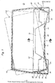
- the device shown has a cup-like container, designated as a whole as 10, which can be closed by means of a removable cover 12 which can be placed thereon.
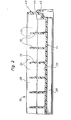
- Partitions 16 forming compartments are arranged on the floor at a parallel distance from one another, together with the floor. These dividing walls forming side walls of the receiving compartments extend symmetrically to the transverse center of the container 10, which is rectangular in plan, and end at a greater distance from its longitudinal side walls 18, 20.
- the device is designed, for example, for storing cassettes with a tape-shaped recording medium, and it is assumed that these cassettes are so-called video cassettes for recording television programs.
- a video cassette set in a receiving compartment of the container 10 is designated as a whole by 22.
- the distance between the partitions 16 can also be chosen so that such video cassettes and case in the opening. have the storage compartments parked.
- the bottom 14 has two tilting edges 24, 26 which extend parallel to the transverse center of the container. These tilting edges are formed by a total of three base partial surfaces 28, 30, 32 of the receiving compartments designated by 34.
- the middle bottom section 30 is in the erected state of the container in a horizontal plane, from which the two outer bottom surfaces 28, 32 extend obliquely outwards and downwards to form the tilting edges 24, 26.
- These bottom partial surfaces of the receiving compartments are approximately only half as long as the horizontal bottom partial surface 30, so that a stable mounting of the video cassettes 22 is ensured in the receiving compartments.
- the longitudinal side walls 18, 20 of the container that delimit the front compartments have a lower wall section 36 that extends obliquely upwards and outwards from below. This wall section is followed by a vertical wall section 38.
- the longitudinal side walls 18, 20 formed by these wall sections form sections of a peripheral wall surrounding the container, which thus also has end walls 40.
- the vertical wall section 38 forms, together with a downward circumferential skirt 42 on the container, a support shoulder 44 on which the cover 12 is removably seated. Accordingly, the projecting collar forming a vertical wandteil- "Tück into the container and fixes it on the cup-like container 10th
- the inclined arrangement of the wall part 36 of the longitudinal side walls 18, 20 creates a degree of freedom in the region of the end faces of the video cassettes 22 set in the receiving compartments 34 of the device, which makes it possible to remove video cassettes from the receiving compartments by tilting them by one to tilt the two tilting edges 24, 26 so that they emerge from the group of cassettes stored in the cup-like container 10 with their upper corner regions in such a way that they can be gripped advantageously.
- the arrangement of the tilting edges on the bottom of the receiving compartments 34 made it possible to dispense with a special mechanism for providing the cassettes in a removal position for this inclination of the video cassettes.
- a video cassette brought into one of the two possible removal positions by tipping is indicated by dash-dotted lines.
- a design variant of the device shown could also be to provide only one tilting edge 24 or 26 on the bottom of the receiving compartments 36.
- the invention is not limited to the construction variant described above. It also permits a design of the device in which it is angular in cross-section in a known manner, and in which the receiving compartments have both a bottom and a rear wall and angled side walls. Basically, the device can have any conceivable design because, according to the invention, it is only a matter of designing the bottom of the storage compartments in such a way that it is possible to incline the objects placed in the storage compartments for the purpose of their removal by tipping.
Landscapes
- Packaging Of Annular Or Rod-Shaped Articles, Wearing Apparel, Cassettes, Or The Like (AREA)
Abstract
Description
Die Erfindung betrifft eine Vorrichtung zum Aufbewahren von im wesentlichen rechteckförmigen Gegenständen, insbesondere Kassetten mit einem bandförmigen Aufzeichnungsträger, mit einer Vielzahl von durch mindestens zwei Seitenwände und einen Boden begrenzten Aufnahmefächern für die Gegenstände.The invention relates to a device for storing essentially rectangular objects, in particular cassettes with a tape-shaped recording medium, with a plurality of receiving compartments for the objects delimited by at least two side walls and a base.
Zum griffbereiten Aufbewahren von Magnetbandkassetten sind Vorrichtungen bekannte deren Aufrahmefächer lediglich zwei Seitenwände, eine Rückwand und einen Boden aufweisen (vgl. DE-GM 75 2562 6; CH-PS 5 82 935).Devices for storing magnetic tape cassettes within reach are known whose cream compartments only have two side walls, a rear wall and a bottom (cf. DE-GM 75 2562 6; CH-PS 5 82 935).
Diese Vorrichtungen sind im Querschnitt winkelförmig ausgebildet und die Kassetten sind hochkant in die Aufnahmefächer hineinzustellen.These devices are angular in cross-section and the cassettes are placed upright in the receiving compartments.
In eingestelltem Zustand der Kassetten in die Aufnahmefächer fluchten die Kassetten-Eckkanten zueinander, so daß diese zu ihrer Entnahme an ihren hochstehenden Längsseiten ergriffen und aus den Aufnahmefächern heruasgezogen werden müssen. Diese Vorrichtungen sind nicht als verschließbare Konstruktionauszubilde Es ist außerdem eine Vorrichtung bekannt, bei der sich die Aufnahmefächer innerhalb eines Aufnahmegehäuses befinden. Jedes Aufnahmefach enthält einen Schieber zur Aufnahme einer Kassette, der in eingeschobenem Zustand zugleich das betreffende Aufnahmefach verschließt. (DE-OS 25 56 609).In the set state of the cassettes in the receiving compartments, the cassette corner edges are aligned with one another, so that they must be grasped on their upstanding long sides and removed from the receiving compartments for their removal. These devices are not to be designed as lockable structures A device is also known in which the receiving compartments are located within a receiving housing. Each receiving compartment contains a slide for receiving a cassette, which at the same time closes the relevant receiving compartment when inserted. (DE-OS 25 56 609).
Zur Kassettenentnahme sind die Schieber im Gehäuse zu entriegeln, wonach sie durch eine Druckfeder selbsttätig aus dem Aufnahmefach herausgeschoben werden. Je Aufnahmefach ist also eine Entriegelungsvorrichtung vorgesehen, wobei jeweils nur eine Kassette zur gleichen Zeit in das Aufnahmegehäuse eingebracht bzw. aus dieser entnommen werden kann.To remove the cassette, the slides in the housing must be unlocked, after which they are automatically pushed out of the storage compartment by a compression spring. An unlocking device is therefore provided for each receiving compartment, it being possible for only one cassette to be inserted into or removed from the receiving housing at a time.
Die der Erfindung zugrunde liegende Aufgabe besteht nun darin, eine Vorrichtung zur Aufbewahrung von rechteckförmigen Gegenständen, insbesondere Kassetten mit einem bandförmigen Aufzeichnungsträger, zu schaffen, deren Konstruktionsprinzip ein Überführen von gespeicherten Gegenständen in eine Stellung ermöglicht, die eine vorteilhafte Entnahme derselben aus der Vorrichtung erlaubt, und zwar sowohl dann, wenn die Vorrichtung mit neben-einanderliegenden frei zugängliche Aufnahmefächem als äuch mit in einem gegebenenfalls verschließbaren Gehäuse untergebrachten Aufnahmefächern ausgestattet ist.The object on which the invention is based is now to create a device for storing rectangular objects, in particular cassettes with a tape-shaped recording medium, the construction principle of which enables stored objects to be transferred into a position which allows them to be advantageously removed from the device, This applies both when the device is equipped with freely accessible receptacles lying next to one another and also with receptacles accommodated in an optionally lockable housing.
Diese Aufgabe wird erfindungsgemäß dadurch gelöst, daß der Boden der Aufnahmefächer mindestens eine sich quer zu dessen Längsrichtung erstreckende Kante zum Abkippen der in die Aufnahmefächer eingebrachten Gegenstände aufweist.This object is achieved in that the bottom of the receiving compartments has at least one edge extending transversely to its longitudinal direction for tipping over the objects placed in the receiving compartments.
Die Anordnung einer Kippkante am Boden der Aufnahmefächer ermöglicht ein Abkippen gespeicherter Gegenstände in den Aufnahmefächern, so daß sie sich relativ zu den benachbarten Gegenständen schräg stellen, bzw. derart verlagern lassen, daß zwei Eckstücke derselben aus der in der Vorrichtung die gleiche Lage einnehmenden Gruppe von Gegenständen austauchen und ergriffen werden können.The arrangement of a tilting edge on the bottom of the receiving compartments allows stored objects in the receiving compartments to be tipped over, so that they can be inclined relative to the adjacent objects, or can be displaced in such a way that two corner pieces thereof from the group of the same position in the device Objects and can be gripped.
Diese Möglichkeit des Schrägstellens der Gegenstände erlaubt insbesondere Personen, die lediglich noch über eine Hand verfügen, eine vorteilhafte Entnahme.This possibility of tilting the objects allows an advantageous removal, in particular for people who only have one hand.
Es ist klar, daß dieses Konstruktionsprinzip ebenso vorteilhaft auch bei Vorrichtungen anwendbar ist, die zur Aufnahme lediglich einer Kassette konzipiert sind.It is clear that this design principle can also be used to advantage in devices which are designed to accommodate only one cassette.
Solche Vorrichtungen weisen üblicherweise ein die Kassette aufnehmendes Gehäuse auf und in diesem ist eine spezielle, technisch aufwendige Vorrichtung vorgesehen, mit deren Hilfe die Kassette entweder bei öffnen oder nach dem öffnen des Gehäuses aus diesem herausbewegt wird (vgl. DE-OS 24 27 103; DE-AS 24 27 108; DD-PS 12 31 41; AT-PS 336 300; CH-PS 608 907).Such devices usually have a housing that accommodates the cassette, and in this a special, technically complex device is provided, with the aid of which the cassette is either moved out of the housing when it is opened or after it is opened (cf. DE-OS 24 27 103; DE-AS 24 27 108; DD-PS 12 31 41; AT-PS 336 300; CH-PS 608 907).
Günstig ist es, wenn der Abstand der Kippkante vom einen Stirnende des Bodens der Aufnahmefächer ungefähr einem Drittel der Gesamtlänge der auf dem Boden zur Auflage kommenden Seite des Gegenstandes entspricht. Dadurch ist eine stabile Auflage von Gegenständen in den Aufnahmefächern gewährleistet.It is expedient if the distance of the tipping edge from one end of the bottom of the receiving compartments corresponds to approximately one third of the total length of the side of the object that comes to rest on the floor. This ensures a stable support of objects in the compartments.
Bei einer bevorzugten Konstruktion weist der Boden der Aufnahmefächer zwei Kippkanten auf, die ungefähr in gleichem Abstand von dessen Längsmitte vorgesehen sind, so daß sich die Gegenstände in zwei entgegengesetzten Richtungen schrägstellen lassen.In a preferred construction, the bottom of the receiving compartments has two tilting edges, which are provided at approximately the same distance from the longitudinal center thereof, so that the objects can be inclined in two opposite directions.
Die Kippkante bzw. -kanten können durch entsprechende, auf dem Boden der Aufnahmefächer vorgesehene Querstege gebildet sein. Wesentlich vorteilhafter ist es jedoch, den Boden der Aufnahmefächer zur Bildung der Kippkanten in Teilflächen aufzugliedern, die einander in stumpfem Winkel zugeordnet sind.The tilting edge or edges can be formed by corresponding transverse webs provided on the bottom of the receiving compartments. However, it is much more advantageous to break down the bottom of the receiving compartments to form the tilting edges into partial areas which are associated with one another at an obtuse angle.
Sofern hierbei die Gegenstände lediglich in einer Richtung abkippbar sein sollen, genügt es, wenn der Boden der Aufnahmefächer zur Bildung der Kippkante zwei einander in stumpfem Winkel zugeordnete Teilflächen aufweist, wobei sich eine vorteilhafte Konstruktion ergibt, wenn beide Teilflächen im spitzen Winkel zur Horizontalen vorgesehen sind. In diesem Falle ruhen die Gegenstände in einer bestimmten Schräglage in den Aufnahmefächern. Sofern die Gegenstände in den Aufnahmefächern in zwei Richtungen abkippbar sein sollen, ist es günstig, die beiden Kippkanten des Bodens der Aufnahmefächer durch insgesamt drei Bodenteilflächen zu bilden, von denen die mittlere Boäenteilfläche im wesentlichen horizontal ist.If the objects are to be tiltable in one direction only, it is sufficient if the bottom of the receptacle Compartments for forming the tipping edge has two sub-areas assigned to one another at an obtuse angle, an advantageous construction resulting if both sub-areas are provided at an acute angle to the horizontal. In this case, the objects rest in a certain inclined position in the receiving compartments. If the objects in the receiving compartments are to be able to be tipped over in two directions, it is expedient to form the two tilting edges of the bottom of the receiving compartments by a total of three bottom partial surfaces, of which the central partial partial surface is essentially horizontal.
Bei einer bevorzugten Ausführungsform der Erfindung sind die Aufnahmefächer innerhalb eines napfartigen Behälters vorgesehen, . dessen Umfangswand mindestens über einen Teil ihrer Höhe von unten schräg nach außen und oben gerichtet ist, wodurch ein Freiheitsgrad für das Schrägstellen der Gegenstände im Behälter geschaffen ist.In a preferred embodiment of the invention, the receiving compartments are provided within a cup-like container. whose peripheral wall is directed obliquely outwards and upwards at least over part of its height, thereby creating a degree of freedom for the inclination of the objects in the container.
Diese Konstruktion ermöglicht es, die Vorrichtung auch verschließbar auszubilden, indem der Behälter mit einem Deckal. ausgestattet werden kanr. Behälter und Deckel können vorteilhaft als aus Kunststoff bestehende Formteile in einem Arbeitsgang hergestellt werden.This construction also makes it possible to design the device to be lockable by the container having a cover. can be equipped Containers and lids can advantageously be produced as molded parts made of plastic in one operation.
Weitere Merkmale und Einzelheiten der Erfindung sind in der sich anschließenden Beschreibung eines in der Zeichnung dargestellten Ausführungsbeispieles einer erfindungsgemäßen Vorrichtung und/oder in den Schutzansprüchen erläutert. In der Zeichnung zeigen:
- Fig. 1 einen Querschnitt durch die einen Verschlußdeckel aufweisende Vorrichtung
- Fig. 2 einen Teillängsschnitt der Vorrichtung entlang der Linie 2-2 der Fig. 1
- Fig. 1 shows a cross section through the device having a closure lid
- 2 shows a partial longitudinal section of the device along the line 2-2 of FIG. 1st
Die gezeigte Vorrichtung weist einen als Ganzes mit 10 bezeichneten napfartigen Behälter auf, der mittels eines auf diesen aufsetzbaren abnehmbaren Deckels 12 verschließbar ist.The device shown has a cup-like container, designated as a whole as 10, which can be closed by means of a
Der Boden des Behälters ist mit 14 bezeichnet. Auf dem Boden sind im Parallelabstand voneinander, zusammen mit dem Boden Aufnahmefächer bildende Trennwände 16 angeordnet. Diese, Seitenwände der Aufnahmefächer bildenden Trennwände erstrecken sich symmetrisch zur Quermitte des im Grundriss rechteckförmigen Behälters 10 und enden in größerem Abstand von dessen Längsseitenwänden 18,20.The bottom of the container is designated 14.
Die Vorrichtung ist beispielsweise zum Aufbewahren von Kassetten mit einem bandförmigen Aufzeichnungsträger ausgebildet, und es sei angenommen, daß es sich bei diesen Kassetten um sogenannte Video-Kassetten zum Aufzeichnen von Televisions-Sendungen handelt. In Fig. 1 ist eine solche in ein Aufnahmefach des Behälters 10 eingestellte Video-Kassette als Ganzes mit 22 bezeichnet. Der Abstand der Trennwände 16 kann hierbei auch so gewählt sein, daß sich solche Video-Kassetten samt Etui in den Auf- . nahmefächern abstellen lassen.The device is designed, for example, for storing cassettes with a tape-shaped recording medium, and it is assumed that these cassettes are so-called video cassettes for recording television programs. In Fig. 1, such a video cassette set in a receiving compartment of the
Wie Fig. 1 zeigt, weist der Boden 14 zwei Kippkanten 24,26 auf, die sich parallel zur Quermitte des Behälters erstrecken. Diese Kippkanten sind durch insgesamt drei Bodenteilflächen 28,30,32 der mit 34 bezeichneten Aufnahmefächer gebildet. Das mittlere Bodenteilstück 30 befindet sich hierbei in aufgestelltem Zustand des Behälters in horizontaler Ebene, von der sich die beiden äußeren Bodenteilflächen 28,32 zur Bildung der Kippkanten 24,26 schräg nach außen und unten erstrecken. Diese Bodenteilflächen der Aufnahmefächer sind ungefähr nur halb so lang wie die horizontale Bodenteilfläche 30, so daß eine stabile Halterung der Video-Kassetten 22 in den Aufnahmefächern gewährleistet ist.As FIG. 1 shows, the
Die die Aufnahmefächer stirnseitig begrenzenden Längsseitenwände 18,20 des Behälters weisen ein unteres Wandteilstück 36 auf, das sich von unten schräg nach oben und außen erstreckt. An dieses Wandteilstück schließt sich ein vertikales Wandteilstück 38 an, Die durch diese wandteilstücke gebildeten Längsseitenwände 18,20 bilden Teilstücke einer den Behälter umgebenden Umfangswand, der damit auch Stirnwände 40 aufweist.The
Das vertikale Wandteilstück 38 bildet zusammen mit einem nach unten gezogenen umlaufenden Schurz 42 am Behälter eine Abstützschulter 44,auf welcher der Deckel 12 abnehmbar aufsitzt. Demgemäß ragt das einen Kragen bildende vertikale wandteil- "tück in den Behälter hinein und fixiert diesen auf dem napfartigen Behälter 10.The
Durch die Schräganordnung des Wandteils 36 der Längsseitenwände 18,20 ist im Bereich der Stirnseiten der in die Aufnahmefächer 34 der Vorrichtung eingestellten Video-Kassetten 22 ein Freiheitsgrad geschaffen, der es ermöglicht, zum Herausnehmen von Video-Kassetten aus den Aufnahmefächern diese durch Abkippen um eine der beiden Kippkanten 24,26 so schräg zu stellen, daß sie aus der im napfartigen Behälter 10 gespeicherten Gruppe von Kassetten mit ihren oberen Eckbereichen so austaucht, daß sie vorteilhaft ergriffen werden kann. Durch die Anordnung der Kippkanten am Boden der Aufnahmefächer 34 konnte für dieses Schrägstellen der Video-Kassetten auf einenspeziellen Mechanismus zum Bereitstellen der Kassetten in eine Entnahmeposition verzichtet werden. In Fig. 1 ist eine durch Abkippen in eine der beiden möglichen Entnahmepositionen gebrachte Video-kassette strichpunktiert angedeutet.The inclined arrangement of the
Eine Konstruktionsvariante zu der gezeigten Vorrichtung könnte auch.darin bestehen, am Boden der Aufnahmefächer 36 lediglich eine Kippkante 24 oder 26 vorzusehen.A design variant of the device shown could also be to provide only one tilting
Die Erfindugn ist nicht auf die vorbeschriebene Konstruktionsvariante beschränkt. Sie läßt auch eine Ausbildung der Vorrichtung zu, bei der diese im Querschnitt in bekannter Weise winkelförmig gestaltet ist ,und bei der die Aufnahmefächer sowohl einen Boden, als auch eine Rückwand sowie winkelförmig verlaufende Seitenwände aufweist. Grundsätzlich kann die Vorrichtung jede denkbare Gestaltung haben, weil es,gemäß der Erfindung, lediglich darauf ankommt, den Boden der Aufnahmefächer so zu gestalten, daß es möglich ist, die in die Aufnahmefächer eingestellten Gegenstände zum Zwecke ihrer Entnahme durch Abkippen schräg stellenzu können.The invention is not limited to the construction variant described above. It also permits a design of the device in which it is angular in cross-section in a known manner, and in which the receiving compartments have both a bottom and a rear wall and angled side walls. Basically, the device can have any conceivable design because, according to the invention, it is only a matter of designing the bottom of the storage compartments in such a way that it is possible to incline the objects placed in the storage compartments for the purpose of their removal by tipping.
Claims (9)
Applications Claiming Priority (2)
| Application Number | Priority Date | Filing Date | Title |
|---|---|---|---|
| DE7922878U | 1979-08-10 | ||
| DE7922878 | 1979-08-10 |
Publications (1)
| Publication Number | Publication Date |
|---|---|
| EP0023977A1 true EP0023977A1 (en) | 1981-02-18 |
Family
ID=6706495
Family Applications (1)
| Application Number | Title | Priority Date | Filing Date |
|---|---|---|---|
| EP80104043A Withdrawn EP0023977A1 (en) | 1979-08-10 | 1980-07-12 | Storage device for articles, particularly recording-tape cassettes |
Country Status (1)
| Country | Link |
|---|---|
| EP (1) | EP0023977A1 (en) |
Cited By (3)
| Publication number | Priority date | Publication date | Assignee | Title |
|---|---|---|---|---|
| US4775049A (en) * | 1986-10-06 | 1988-10-04 | Ernst Stadelmann Gesellschaft M.B.H. | Container for generally flat articles |
| EP0335572A2 (en) * | 1988-03-30 | 1989-10-04 | Wright Line Inc. | Storing and dispensing system |
| JPH0651173U (en) * | 1992-12-22 | 1994-07-12 | 株式会社岡村製作所 | Holding frame for magnetic tape cases, etc. |
Citations (7)
| Publication number | Priority date | Publication date | Assignee | Title |
|---|---|---|---|---|
| FR2010916A1 (en) * | 1968-06-14 | 1970-02-20 | Stembel Oren | |
| US3743081A (en) * | 1971-02-25 | 1973-07-03 | Grace W R & Co | Cassette album container |
| US3811745A (en) * | 1972-09-29 | 1974-05-21 | E Cylke | Cassette carrier |
| DE2427103A1 (en) * | 1974-06-05 | 1975-12-18 | Idn Invention Dev Novelties | CONTAINER FOR STORING MAGNETIC TAPE CASSETTES |
| FR2274109A1 (en) * | 1974-06-05 | 1976-01-02 | Idn Invention Dev Novelties | STORAGE CONTAINER FOR MAGNETIC TAPE CASSETTES |
| DE2507620A1 (en) * | 1975-02-21 | 1976-09-02 | Wittner Rudolf | Container for large number of cassettes - is subdivided by partition walls held in position by projections on inner surface of side walls |
| FR2412136A1 (en) * | 1977-12-16 | 1979-07-13 | Novita Stella Di Stella Ettore | CASE INTENDED TO CONTAIN CASSETTES OF MAGNETIC RIBBONS |
-
1980
- 1980-07-12 EP EP80104043A patent/EP0023977A1/en not_active Withdrawn
Patent Citations (8)
| Publication number | Priority date | Publication date | Assignee | Title |
|---|---|---|---|---|
| FR2010916A1 (en) * | 1968-06-14 | 1970-02-20 | Stembel Oren | |
| US3743081A (en) * | 1971-02-25 | 1973-07-03 | Grace W R & Co | Cassette album container |
| US3811745A (en) * | 1972-09-29 | 1974-05-21 | E Cylke | Cassette carrier |
| DE2427103A1 (en) * | 1974-06-05 | 1975-12-18 | Idn Invention Dev Novelties | CONTAINER FOR STORING MAGNETIC TAPE CASSETTES |
| FR2274109A1 (en) * | 1974-06-05 | 1976-01-02 | Idn Invention Dev Novelties | STORAGE CONTAINER FOR MAGNETIC TAPE CASSETTES |
| FR2274106A1 (en) * | 1974-06-05 | 1976-01-02 | Idn Invention Dev Novelties | MAGNETIC TAPE CASSETTE STORAGE CONTAINER |
| DE2507620A1 (en) * | 1975-02-21 | 1976-09-02 | Wittner Rudolf | Container for large number of cassettes - is subdivided by partition walls held in position by projections on inner surface of side walls |
| FR2412136A1 (en) * | 1977-12-16 | 1979-07-13 | Novita Stella Di Stella Ettore | CASE INTENDED TO CONTAIN CASSETTES OF MAGNETIC RIBBONS |
Cited By (4)
| Publication number | Priority date | Publication date | Assignee | Title |
|---|---|---|---|---|
| US4775049A (en) * | 1986-10-06 | 1988-10-04 | Ernst Stadelmann Gesellschaft M.B.H. | Container for generally flat articles |
| EP0335572A2 (en) * | 1988-03-30 | 1989-10-04 | Wright Line Inc. | Storing and dispensing system |
| EP0335572A3 (en) * | 1988-03-30 | 1990-06-13 | Wright Line Inc. | Storing and dispensing system |
| JPH0651173U (en) * | 1992-12-22 | 1994-07-12 | 株式会社岡村製作所 | Holding frame for magnetic tape cases, etc. |
Similar Documents
| Publication | Publication Date | Title |
|---|---|---|
| DE3410480C2 (en) | ||
| EP0253102A1 (en) | Storage device for magnetic tape cassettes | |
| EP0476343A2 (en) | Box for screwdriver bits | |
| DE3730813C1 (en) | Tape cassette housing with coupling elements | |
| EP0023977A1 (en) | Storage device for articles, particularly recording-tape cassettes | |
| EP0360987B1 (en) | Tool case | |
| DE2046248A1 (en) | Transparency magazine | |
| DE4021257A1 (en) | Drawer installed underneath aquarium - rests on support plate of underneath structure, and runs along guides, and has front, two spaced apart sides, base and shelves | |
| DE6800540U (en) | DEVICE FOR TRANSPORTING BOTTLES | |
| DE8137602U1 (en) | STACKABLE STORAGE CONTAINER WITH EXTENDING DRAWER | |
| DE2025373A1 (en) | Bottle carrier that can be used in boxes or transport and storage boxes | |
| EP0367168B1 (en) | Crate for bottles | |
| DE7922878U1 (en) | Device for storing objects, in particular cassettes with a tape-shaped recording medium | |
| DE2615457A1 (en) | Casette tape storage magazine - has drawer in two halves hingeing together on transverse axis | |
| DE3508490A1 (en) | Apparatus for the differentiated storage of question and answer cards | |
| EP0896863A2 (en) | Tool holding rack | |
| EP0927564B1 (en) | Bridge - bid - box | |
| DE2005601C (en) | Stackable storage tray | |
| EP0487824B1 (en) | Plastic bottle crate | |
| EP0201664B1 (en) | Display rack for selling shoe-laces, packages of shoe-laces or similar haberdashery | |
| DE1486219A1 (en) | Tube container | |
| DE4402219A1 (en) | Stacking container with window | |
| DE1168332B (en) | Storage container for slide magazines | |
| DE202018101695U1 (en) | Box with lid | |
| DE2724572A1 (en) | SALES STAND |
Legal Events
| Date | Code | Title | Description |
|---|---|---|---|
| PUAI | Public reference made under article 153(3) epc to a published international application that has entered the european phase |
Free format text: ORIGINAL CODE: 0009012 |
|
| AK | Designated contracting states |
Designated state(s): AT BE CH IT NL SE |
|
| 17P | Request for examination filed |
Effective date: 19810518 |
|
| STAA | Information on the status of an ep patent application or granted ep patent |
Free format text: STATUS: THE APPLICATION HAS BEEN WITHDRAWN |
|
| 18W | Application withdrawn |
Withdrawal date: 19820825 |
|
| RIN1 | Information on inventor provided before grant (corrected) |
Inventor name: HAERLE, FRITZ |