EP0020199B1 - System for controlling the changing of the read side for the optical reader of an information carrier - Google Patents
System for controlling the changing of the read side for the optical reader of an information carrier Download PDFInfo
- Publication number
- EP0020199B1 EP0020199B1 EP80400552A EP80400552A EP0020199B1 EP 0020199 B1 EP0020199 B1 EP 0020199B1 EP 80400552 A EP80400552 A EP 80400552A EP 80400552 A EP80400552 A EP 80400552A EP 0020199 B1 EP0020199 B1 EP 0020199B1
- Authority
- EP
- European Patent Office
- Prior art keywords
- signal
- face
- control
- output
- logic
- Prior art date
- Legal status (The legal status is an assumption and is not a legal conclusion. Google has not performed a legal analysis and makes no representation as to the accuracy of the status listed.)
- Expired
Links
Images


Classifications
-
- G—PHYSICS
- G11—INFORMATION STORAGE
- G11B—INFORMATION STORAGE BASED ON RELATIVE MOVEMENT BETWEEN RECORD CARRIER AND TRANSDUCER
- G11B19/00—Driving, starting, stopping record carriers not specifically of filamentary or web form, or of supports therefor; Control thereof; Control of operating function ; Driving both disc and head
- G11B19/02—Control of operating function, e.g. switching from recording to reproducing
-
- G—PHYSICS
- G11—INFORMATION STORAGE
- G11B—INFORMATION STORAGE BASED ON RELATIVE MOVEMENT BETWEEN RECORD CARRIER AND TRANSDUCER
- G11B7/00—Recording or reproducing by optical means, e.g. recording using a thermal beam of optical radiation by modifying optical properties or the physical structure, reproducing using an optical beam at lower power by sensing optical properties; Record carriers therefor
- G11B7/08—Disposition or mounting of heads or light sources relatively to record carriers
- G11B7/085—Disposition or mounting of heads or light sources relatively to record carriers with provision for moving the light beam into, or out of, its operative position or across tracks, otherwise than during the transducing operation, e.g. for adjustment or preliminary positioning or track change or selection
Definitions
- the invention relates to a control system for changing the read face for an optical reader of an information medium, and in particular of a video disc.
- the correct focusing of the light brush is most often obtained by means of a focusing servo device comprising a feedback loop keeping the distance between the optical device and the engraved surface of the disc constant.
- the attachment and the maintenance of the servo device are obtained by the detection of the electrical signal corresponding to the engraving.
- the simplest way to obtain the passage of the focusing, and therefore of the reading, from one face to the other consists in opening the loop of the focusing servo control device for a preset time T and operating at focusing device a translational movement corresponding to the movement from one face of the disc to the other face.
- This translational movement is obtained by applying to the focusing device a current pulse correctly calibrated in duration and in amplitude so that the device moves exactly the thickness of the disc during the time T. At this instant, it suffices to close the loop of the focusing servo device so that it hooks onto the opposite face. This very simple process does not give satisfactory results in practice.
- the translational movement from one face to the other comprises two phases: during the first phase the focusing device is animated by a uniformly accelerated movement during the duration of the current pulse ; during the second phase, the device is animated by a ballistic movement depending on the speed acquired during the first phase.
- this speed as well as the path traveled during this first phase, depend not only on the acceleration that is applied to the focusing device by means of the calibrated pulse but also on the initial speed of movement of this device at the instant of application of the current pulse.
- the friction of the mechanical parts of the focusing device can vary as a function of temperature, humidity or other parameters that are difficult to control.
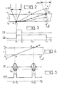
- Figure 1 illustrates the mechanism of the optical reading of a transparent videodisc engraved on its two faces.
- the focusing device as well as the recording method by burning microcuvettes on a video disc are well known to those skilled in the art. This device and this method are outside the scope of the invention. It is however useful to recall its general principles.
- a light brush produced by a laser (not shown in FIG. 1) is focused on one of the faces, for example the face f 2 , of a video disc using an optical system symbolized by the lens L in position II, the optical center of this lens L (II) is located on an axis Y 2 , parallel to the axis Y of the reference triede XYZ drawn in FIG. 1.
- This videodisc comprises concentric tracks comprising microcuvettes 3 on the side f 1 and 2 on the side f 2 . These microcuvettes represent coded information. This information is read by focusing the beam 6 on these microcuvettes. In FIG. 1, this focusing is illustrated by the spot A. The light rays are then diffracted by the microcuvettes and detected by photoelectric cells 4 and 5, the outputs S and S 2 of which are connected to the inputs of a differential amplifier not shown. The diffraction spot in the plane of cells 4 and 5 is illustrated in FIG. 1 by the reference A 1 . The beam, focused on the face f2, forms a spot A 2 on the face f 1 whose dimensions are much larger than the dimensions of the microcuvettes 3 etched on this face. The light rays focused on the face f 2 are therefore not disturbed by the microcuvettes 3 when crossing this face. Under these conditions, the etching of the face f 1 has no influence on the electrical signal delivered by the cells placed under the disc 4 and 5.
- the photoelectric cells 4 and 5 will therefore detect a high frequency signal modulated respectively by the microcuvettes 3 or 2.
- This signal is used on the one hand for the actual reading of the information and, on the other hand, to open or close the feedback loop of the servo device. To do this, high frequency signals are detected. This process is well known to those skilled in the art and will not be described further.
- FIGS 2 and 3 illustrate the process for changing the face read in the known art, described above.
- the focusing device is slaved to the side f 2 of the video disc 1.
- This signal has a duration T equal to t, t 3 .
- a calibrated pulse IS is applied to the organs controlling the movement of the focusing device for a time equal to the duration t 1 t 2 .
- This pulse is intended to impart to the focusing device a translational movement towards the face f 1 , which it is assumed to reach at point B after a time T equal to t 1 t 3 .
- t 3 it suffices to close the feedback loop of the focusing servo device so that it hooks onto the new read face, that is to say the face f 1 .
- the focusing device symbolized by the optic L (I) is animated by a uniformly accelerated movement towards position II.
- the speed acquired during this first phase depends not only on the acceleration that is applied to the focusing device by means of the calibrated pulse but also on the initial speed of movement of this device at time t 1 .
- This initial speed is added algebraically to the acquired speed. It follows that under certain conditions the focusing device moves more or less quickly than the speed of movement corresponding to the average trajectory AB. For a higher speed of displacement, one obtains for example the trajectory AB 'D during time T and for a lower speed of displacement, one obtains the trajectory A C. It follows that in the first case, the crossing of the face f 1 is done at point B ', that is to say at time t 3 whereas in the second case, at time t 3 , point A is at C and has not yet crossed face f 1 . Points D and C are too far from face f, to obtain rapid and correct attachment of the focusing servo device to side f 1 of the video disc when the feedback loop of the servo device is closed again .
- Detection includes a recovery operation and an integration operation.
- the "HFD" pulse has a logic level "1 during the intervals t 1 t 2 and t 3 t 4.
- the durations of these intervals are precisely determined by a logic with threshold D s .
- the threshold D s being chosen high enough to eliminating any parasitic noise signals and unambiguously discriminating the appearance of the high frequency signal.
- the loop of the focusing servo-control device is opened, by means of the signal OB, at the same time as a short command pulse is applied to it.
- IS face jump Under the effect of this pulse, the focal point leaves the face f 2 of the videodisc at point A to go towards the face f 1 along the path AB, which has the effect of extinguishing the high frequency HF signal from reading of the face f 2 , causing the tilting of the detected signal HFD, when the high frequency signal decreases below the predetermined threshold D s .
- the focal point will cross the face f 1 .
- the high frequency HF signal will start to grow again for reach the threshold D S. It follows that the detected signal HFD switches again, this transition causing in turn, the switching of the signal OB and the closing of the feedback loop of the focusing servo device, causing it to catch on. on side f, of the disc. In synchronism with the closing of the loop, a braking pulse is sent to the focusing device to avoid the ballistic shift of the point B, this pulse having a polarity opposite to the acceleration pulse.
- the process for passing from face f 1 to face f 2 comprises the same steps, it is only necessary to reverse the respective directions of the acceleration and braking pulses. These pulses can be generated in a very simple manner, by differentiating the signal for opening / closing loop OB or its complement.
- the servo device works absolutely safely when the disc does not have any engraving on one of its faces, this non-engraved face delivering no signal, it is not possible that the servo - mechanism focus can hang on to it. It is not the same if the two sides of the disc carry engraved information, in fact each of the faces being able to deliver a modulated electrical signal, the control device can be hooked either on one or the other. 'other without it being possible to differentiate them, especially during the initial hanging. In addition, under the influence of transient parasitic signals, an unwanted change of face can occur. In this case, if for example the previously read face was the face f 1 , the control device will remain attached to the face f 2 and the information read will be the information engraved on. the side f 2 .
- any process and device can be used to recognize the read face.
- This record can contain 40 bits.
- a bit is added to the bit stream representing the sound channel.
- the bits of the sound channel carry numbers ranging from 1 to 40.
- An additional bit identifies the read face. This bit is permanently carried to the logical level "0" for one of the faces and to the logical level "1" for the other face. This bit as well as the sound bits are recorded during the line scan return interval.
- this additional bit representing the read face is transmitted to the read face change control system.
- FIG. 8 describes a preferred embodiment of the control system for changing the face read according to the invention.
- Reference 1 represents the usual circuits of a video disc player as well as the associated clock and synchronization circuits, providing in particular the clock signals H 3 at the line scanning frequency necessary for the device for controlling the face. read, represented in FIG. 8 by the reference DSU.
- These circuits also provide the additional bit representing the face read on the connection 42 as well as the high frequency HF signal coming from the reading of the information engraved on one or the other face and a direct voltage V representing the logic level "1" according to the standard of integrated circuits used. This last voltage is in the case of a standard called "TTL", of 5 volts.
- the face change control system essentially comprises three circuits.
- a first control circuit CD 1 producing a binary signal Cd of "read-side change command”
- a second control circuit CD 2 producing the loop open / close signal OB
- a generator GE producing a control pulse IS side jump
- the circuit CD can be constituted simply by a switch to. two directions, alternately connecting the output Cd to a logic value "1" (V) or a logic value "0" (symbolized by the circuit earth).
- the additional bit identifying the read face arrives on an input of the "EXCLUSIVE" door 8, this door receives on its other input is the control signal Cd.
- this gate 8 Depending on the position of the switch for choosing the face of the control circuit CD 1 , this gate 8 lets the additional bit pass without modification, this is the case for example of the face f, for which this bit is by convention always at “0" or, and this is the case of face f 2 , for which the additional bit is always at "1", gate 8 reverses the bit.
- the output of the "EXCLUSIVE" gate 80 is transmitted to the serial input of a shift register 3 with eight parallel outputs (30-1 / 30-8). When one is correctly positioned on the desired side by CD 1 , the entry of the shift register 3 receives only "0" (apart from possibly some erroneous bits due to alterations occurring during the transcription process).
- the CD switch If, being positioned on one of the sides of the disc, in stabilized reading mode, the CD switch is operated from one position to the other, which is the case on the timing diagram of FIG. 9 at the moment t o , the switching of this switch causes, via gate 8, a change of state of the consecutive additional bits arriving at input 80 of the shift register 3. It is then a succession of bits all at level "1" who enter this register. At the end of the eighth consecutive bit at level "1" entered in register 3, that is to say at the end of time t 7 , it has level 1 on all outputs 30-1 to 30-8, which causes the change of state from "1" to "0" of the SA output of door 4.
- This change of state triggers a monostable flip-flop 5, which by its reverse output Q 5 causes the flip-flop of a bistable flip-flop of type RS: 7 formed by the two "NAND” gates 71 and 72.
- the output Q of this flip-flop provides the signal for opening / closing of feedback loop OB.
- the high frequency HF signals originating from the reading of the etchings representing the recorded information are detected, that is to say rectified and integrated, by a circuit 2 providing a detected HFD signal, inverted by the inverter 100 and transmitted to the input R of the flip-flop 7.
- Circuit 2 also includes threshold logic intended to eliminate noise.
- the "EXCLUSIVE" gate 9 and the RC differentiation circuit are intended to deliver face jump and braking pulses of suitable polarity.
- the circuit can only deliver pulses making it possible to perform a jump from face f 2 towards face f 1 , and when CD 1 is positioned on face f 2 , the "OU-EXCLUSIVE" gate 9 becoming inverting, the pulses delivered only allow the passage from face f 1 to face f 2 .
- the bistable flip-flop 7 is controlled by the output Q 5 of the monostable flip-flop 3 on its input 5 and the HFD signal on its input R, Or, if the change to "0" of the output Q 3 of the monostable flip-flop 5 causes good the passage to "1" of the output Q 7 of the flip-flop 7, this state remains fleeting as long as the input R has not passed to the state "1", which only intervenes when under the effect of the jump pulse IS, the focal point of the reading device is sufficiently distant from the engraving of the face that one wants to leave.
- the command on input S must therefore be maintained for a sufficiently long time (approximately 500 ms), this is the purpose of the monostable flip-flop 5.
- the monostable flip-flop 6 is intended for its part to prevent access to register 3 additional bits, necessarily erroneous, which arrive during the passage time from one face to the other and thus avoid the production of erroneous pulses SA.
- This monostable rocker 6 produces pulses of sufficient length to allow the various servomechanisms to stabilize on the new face after each jump (approximately 100 to 250 milliseconds).
- the reset input (RESET) of register 3 is connected to output Q 6 of the monostable flip-flop 6. Thus, it is not allowed to change the faces again before this time has elapsed.
- the face control device read DSU constantly checks that the focusing servo mechanism is correctly positioned on the face of the disc that has been selected. Indeed if this were not the case, the additional bits would arrive at state "1" on input 80 of the shift register 3, and at the end of the eighth consecutive bit in state "1" would automatically trigger the previously described process of face change. This is particularly useful for automatically positioning the reading device on the chosen side when changing discs.
- the differentiator circuit 200 can be constituted by a resistor with a typical value of 10 K ⁇ and a capacitor with a typical value of 10,000 pF.
Description
L'invention concerne un système de commande de changement de face lue pour lecteur optique d'un support d'information, et en particulier d'un vidéodisque.The invention relates to a control system for changing the read face for an optical reader of an information medium, and in particular of a video disc.
Il est bien connu que la lecture d'informations gravées sur une face ou les deux faces d'un vidéodisque transparent peut s'effectuer au moyen d'un pinceau lumineux, provenant par exemple d'un laser, que l'on doit focaliser sur la surface gravée, à l'aide de moyens optiques appropriés. Des cellules photo-électriques disposées sous le disque reçoivent la lumière diffractée par la gravure constituée par exemple par des microcuvettes, délivrant ainsi un signal électrique modulé par l'information gravée sur le disque.It is well known that the reading of information engraved on one side or both sides of a transparent video disc can be carried out by means of a light brush, for example from a laser, which must be focused on the engraved surface, using appropriate optical means. Photoelectric cells placed under the disc receive the light diffracted by the etching constituted for example by microcuvettes, thus delivering an electrical signal modulated by the information etched on the disc.
Dans le cas d'un vidéodisque portant des informations gravées sur ses deux faces, pour lire la face 2 (f2), il suffit d'effectuer un translation du point de focalisation vers cette face 2- (f2), en déplaçant par exemple le système optique de focalisation selon une direction normale au plan du disque. La tache lumineuse dans ces conditions devient de dimensions convenables pour pouvoir lire avec précision les microcuvettes formant la gravure de la face 2 (f2), elle est par contre beaucoup trop grande pour pouvoir être influencée par la gravure de la face 1 (fl). Il suffit donc dans la pratique de déplacer le point de focalisation de façon convenable, pour pouvoir passer immédiatement de la lecture d'une des faces du disque à la lecture de l'autre face, sans avoir à retourner le disque, comme c'est le cas dans la plupart des systèmes de disque double face (par exemple les disques audio).In the case of a videodisc carrying information engraved on its two sides, to read side 2 (f 2 ), it suffices to translate the focal point towards this side 2- (f 2 ), by moving by example the optical focusing system in a direction normal to the plane of the disc. The light spot under these conditions becomes of suitable dimensions to be able to read with precision the microcuvettes forming the etching of the side 2 (f 2 ), it is however much too large to be able to be influenced by the etching of the side 1 (f l ). It is therefore sufficient in practice to move the focal point in a suitable manner, in order to be able to immediately pass from reading from one side of the disc to reading from the other side, without having to turn the disc, as is the case in most double-sided disc systems (eg audio discs).
Par ailleurs, il est également connu que la focalisation correcte du pinceau lumineux est obtenue le plus souvent au moyen d'un dispositif d'asservissement de focalisation comportant une boucle de rétroaction maintenant constante la distance entre le dispositif optique et la surface gravée du disque. L'accrochage et le maintien du dispositif d'asservissement sont obtenus par la détection du signal électrique correspondant à la gravure.Furthermore, it is also known that the correct focusing of the light brush is most often obtained by means of a focusing servo device comprising a feedback loop keeping the distance between the optical device and the engraved surface of the disc constant. The attachment and the maintenance of the servo device are obtained by the detection of the electrical signal corresponding to the engraving.
Le moyen le plus simple d'obtenir le passage de la focalisation, et donc de la lecture, d'une face à l'autre, consiste à ouvrir la boucle du dispositif d'asservissement de focalisation pendant un temps T préétabli et faire opérer au dispositif de focalisation un mouvement de translation correspondant au déplacement d'une face du disque à l'autre face. Ce mouvement de translation est obtenu en appliquant au dispositif de focalisation une impulsion de courant correctement calibrée en durée et en amplitude de manière à ce que le dispositif se déplace exactement de l'épaisseur du disque pendant le temps T. A cet instant, il suffit de refermer la boucle du dispositif d'asservissement de focalisation pour que celui-ci s'accroche sur la face opposée. Ce procédé très simple ne donne pas de résultats satisfaisants dans la pratique.The simplest way to obtain the passage of the focusing, and therefore of the reading, from one face to the other, consists in opening the loop of the focusing servo control device for a preset time T and operating at focusing device a translational movement corresponding to the movement from one face of the disc to the other face. This translational movement is obtained by applying to the focusing device a current pulse correctly calibrated in duration and in amplitude so that the device moves exactly the thickness of the disc during the time T. At this instant, it suffices to close the loop of the focusing servo device so that it hooks onto the opposite face. This very simple process does not give satisfactory results in practice.
Bien que l'ordre de grandeur des sauts à effectuer et que les problèmes qui se posent ne soient pas de nature identique à ceux que vise à résoudre la présente invention, l'utilisation d'une impulsion calibrée peut être illustrée dans le cadre particulier du saut d'une piste à l'autre sur une même face de disque par référence à la demande de brevet FR-A-2 321 808. Il est fait notamment allusion aux risques de dépassement de la piste souhaitée encourus par la mise en oeuvre d'une telle méthode, ce en relation avec les figures 3a à 3d et du texte de la description associé.Although the order of magnitude of the jumps to be made and the problems which arise are not of an identical nature to those which the present invention aims to solve, the use of a calibrated pulse can be illustrated in the particular context of jump from one track to another on the same face of the disc by reference to patent application FR-A-2 321 808. Reference is made in particular to the risks of going beyond the desired track incurred by the implementation of 'Such a method, this in relation to Figures 3a to 3d and the text of the associated description.
Dans le cadre du changement de face lue, le mouvement de translation d'une face à l'autre comporte deux phases: pendant la première phase le dispositif de focalisation est animé d'un mouvement uniformément accéléré pendant la durée de l'impulsion de courant; pendant la deuxième phase, le dispositif est animé d'un mouvement balistique fonction de la vitesse acquise pendant le première phase. Or, cette vitesse, ainsi que le trajet parcouru pendant cette première phase, dépendent non seulement de l'accélération que l'on applique au dispositif de focalisation au moyen de l'impulsion calibrée mais également de la vitesse initiale de déplacement de ce dispositif à l'instant d'application de l'impulsion de courant. S'agissant d'un système d'asservissemnet bouclé corrigeant constamment l'erreur de focali- setion, cette vitesse initiale est rarement nulle et vient s'additionner algébriquement à la vitesse communiquée au dispositif de focalisation, ce qui a pour conséquence d'amplifier ou de réduire le mouvement de translation opéré par le dispositif de focalisation pendant le temps T.As part of the change of face read, the translational movement from one face to the other comprises two phases: during the first phase the focusing device is animated by a uniformly accelerated movement during the duration of the current pulse ; during the second phase, the device is animated by a ballistic movement depending on the speed acquired during the first phase. However, this speed, as well as the path traveled during this first phase, depend not only on the acceleration that is applied to the focusing device by means of the calibrated pulse but also on the initial speed of movement of this device at the instant of application of the current pulse. Being a looped servo system constantly correcting the focusing error, this initial speed is seldom zero and is added algebraically to the speed communicated to the focusing device, which has the consequence of amplifying or reduce the translational movement operated by the focusing device during time T.
En outre, du fait de l'accélération de la pesanteur les mouvements de translation de la face 1 vers la face 2 ou de la face 2 vers la face 1 sont différents. Enfin, d'autres paramètres peuvent influencer ce mouvement de translation: les frottements des parties mécaniques du dispositif de focalisation peuvent varier en fonction de la température, de l'humidité ou d'autres paramètres difficilement contrôlables.In addition, due to the acceleration of gravity, the translational movements from
Il est donc extrêmement délicat et peu fiable de réaliser le passage d'une face à l'autre par un procédé consistant à assigner une durée prédéterminée au changement de face.It is therefore extremely delicate and unreliable to carry out the passage from one face to the other by a process consisting in assigning a predetermined duration to the change of face.
Pour pallier ces inconvénients l'invention a pour objet un système de changement de face lue pour lecteur optique de support d'information enregistrée sur ses deux faces, la lecture s'effectuant à l'aide d'un dispositif optique focalisant un faisceau lumineux sur l'une des faces préalablement choisie; dispositif optique comportant des circuits de commande de focalisation comprenant une boucle de rétroaction, pour maintenir constante la distance entre le dispositif optique et la surface du support par asservissement sur un signal électrique, la lecture des informations enregistrées fournissant un signal électrique modulée haute fréquence et des moyens de détection recevant le signal électrique modulé haute fréquence dont la sortie fournit un signal détecté se présentant sous la forme d'un signal binaire prenant une première valeur logique lorsque l'àmplitude du signal haute fréquence est supérieure à un seuil prédéterminé et une seconde valeur ligique lorsque l'amplitude du signal haute fréquence est inférieure à ce seuil; système caractérisé en ce qu'il comporte:
- ―des premiers moyens de commande pour générer un signal binaire de commande de changement de face lue dont les deux niveaux logiques représentent les deux faces à lire;
- - des seconds moyens de commande combinant le signal détecté et le signal de commande de changement de face lue pour créer un signal binaire d'ouverture/fer- meture de boucle de rétroaction, prenant un premier niveau logique commandant l'ouverture de la boucle de rétroaction, après réception d'une transition du signal de commande de changement de face lue et un second niveau logique commandant à nouveau la fermeture de la boucle de retroaction après réception d'une transition du signal détecté, de la seconde à la première valeur logique;
- - et un générateur d'impulsion de commande de saut de face connecté aux sorties des premiers et seconds moyens de commande fournissant au circuit de commande de focalisation une impulsion de commande de saut de face en synchronisme avec les transitions du signal d'ouverture/fermeture de boucle de rétroaction; la polarité de l'impulsion de commande étant choisie telle qu'elle communique alternativement au dispositif optique de focalisation un mouvement accéléré vers la face préalablement choisie lors de la transition du second au premier niveau logique du signal d'ouver- ture/fermeture de la boucle de rétroaction et une décélération lors du retour au second niveau logique permettant la focalisation sur la face choisie.
- Premiersfirst control means for generating a binary signal for changing the read face command, the two logic levels of which represent the two faces to be read;
- - second control means combining the detected signal and the read face change control signal to create a binary opening / closing feedback loop signal, taking a first logic level controlling the opening of the feedback loop feedback, after reception of a transition from the read change of control signal and a second logic level again commanding the closure of the feedback loop after reception of a transition of the detected signal, from the second to the first logic value ;
- - And a face jump control pulse generator connected to the outputs of the first and second control means supplying the focusing control circuit with a face jump control pulse in synchronism with the transitions of the opening / closing signal. feedback loop; the polarity of the control pulse being chosen such that it alternately communicates to the optical focusing device an accelerated movement towards the face previously chosen during the transition from the second to the first logic level of the opening / closing signal of the feedback loop and deceleration when returning to the second logical level allowing focusing on the chosen face.
L'invention sera mieux comprise et d'autres caractéristiques apparaîtront à la lecture de la description ci-après en se référant aux dessins annexés parmi lesquels:
- ― la figure 1 illustre le mécanisme de la lecture d'un vidéodisque transparent gravé sur ses deux faces.
- - la figure 2 et le chronogramme de la figure 3 illustrent un premier procédé de commande de changement de face de lecture selon l'art connu.
- ―les figures 4 et 5 illustrent les phenomènes mis en jeu dans l'invention.
- - les figures 6 et 7 illustrent les dispositions retenues par l'invention.
- -la figure 8 est un système de commande de changement de face lue selon l'invention.
- ―la figure 9 est un chronogramme afférent à la figure 8.
- - Figure 1 illustrates the mechanism for reading a transparent video disc engraved on both sides.
- - Figure 2 and the timing diagram of Figure 3 illustrate a first method for controlling the reading side change according to the prior art.
- ― Figures 4 and 5 illustrate the phenomena involved in the invention.
- - Figures 6 and 7 illustrate the arrangements adopted by the invention.
- FIG. 8 is a control system for changing the face read according to the invention.
- 9 Figure 9 is a timing diagram relating to Figure 8.
La figure 1 illustre le mécanisme de la lecture optique d'un vidéodisque transparent gravé sur ses deux faces. Le dispositif de focalisation ainsi que le procédé d'enregistement par gravure de microcuvettes sur un vidéodisque sont bien connus de l'homme de métier. Ce dispositif et ce procédé sortent du cadre de l'invention. Il est cependant utile d'en rappeler les principes généraux. Un pinceau lumineux produit par un laser (non représenté sur la figure 1) est focalisé sur l'une des faces, par exemple la face f2, d'un vidéodisque à l'aide d'un système optique symbolisé par la lentille L dans la position II, le centre optique de cette lentille L (II) est situé sur un axe Y2, parallèle à l'axe Y du triède de référence XYZ dessiné sur la figure 1. Il a été dessiné sur la figure 1 un fragment de vidéodisque en matière transparente d'épaisseur. Ce vidéodisque comporte des pistes concentriques comportant des microcuvettes 3 sur la face f1 et 2 sur la face f2. Ces microcuvettes représentent des informations codées. La lecture de ces informations s'effectue par focalisation du faisceau 6 sur ces microcuvettes. Sur la figure 1, cette focalisation est illustrée par le spot A. Les rayons lumineux sont ensuite diffractés par les microcuvettes et détectés par des cellules photo-électriques 4 et 5, dont les sorties S et S2 sont connectées aux- entrées d'un amplificateur différentiel non représenté. La tache de diffraction dans le plan des cellules 4 et 5 est illustrée sur la figure 1 par la référence A1. Le faisceau, focalisé sur la face f2, forme une tache A2 sur la face f1 dont les dimensions sont beaucoup plus grandes que les dimensions des microcuvettes 3 gravées sur cette face. Les rayons lumineux focalisés sur la face f2 ne sont donc pas perturbés par les microcuvettes 3 à la traversée de cette face. Dans ces conditions la gravure de la face f1 n'a aucune influence sur le signal électrique délivré par les cellules placées sous le disque 4 et 5.Figure 1 illustrates the mechanism of the optical reading of a transparent videodisc engraved on its two faces. The focusing device as well as the recording method by burning microcuvettes on a video disc are well known to those skilled in the art. This device and this method are outside the scope of the invention. It is however useful to recall its general principles. A light brush produced by a laser (not shown in FIG. 1) is focused on one of the faces, for example the face f 2 , of a video disc using an optical system symbolized by the lens L in position II, the optical center of this lens L (II) is located on an axis Y 2 , parallel to the axis Y of the reference triede XYZ drawn in FIG. 1. A fragment of videodisc in transparent thick material. This videodisc comprises concentric
Si l'on désire lire l'information gravée sur ia face f1, il suffit donc de focaliser le faisceau 6 sur cette face. Cette focalisation est réalisée en déplaçant le dispositif de focalisation, et en particulier l'optique L d'une distance ΔZ. pour passer de la position Il à la position I, parallèlement à l'axe Z de référence. Il doit être rappelé que le vidéodisque est animé d'un mouvement de rotation que se traduit au voisinage de la tache de focalisation A par un mouvement sensiblement parallèle à l'axe Y. Ce mouvement est symbolisé sur la figure 1 par la flèche F. Pendant le temps nécessaire au déplacement de la lentille L de la position Il à la position le disque continuant à tourner (et les microcuvettes ayant continué de défiler sous le faisceau de lecture), le faisceau lumineux se focalisera en B. Les positions relatives du vidéodisque 1 et du dispositif de focalisation en position Il sont illustrées sur la partie droite de la figure 1 en pointillé. Il va de soi que le mouvement du dispositif de focalisation se fait selon le seul axe Z et que les détecteurs restent immobiles dans l'espace. Le centre optique de la lentille L (II) se trouve maintenant sur l'axe Y1. La focalisation se faisant désormais sur la face f1, les rayons lumineux sont diffractés en B1.If one wishes to read the information engraved on ia face f 1 , it is therefore sufficient to focus the
Que la focalisation se fasse sur la face f1 ou sur la face f2, le vidéodisque étant animé d'un mouvement de rotation, les cellules photo-électriques 4 et 5 vont donc détecter un signal haute fréquence modulé respectivement par les microcuvettes 3 ou 2. Ce signal est utilisé d'une part pour la lecture proprement dite des information et, d'autre part, pour ouvrir ou fermer la boucle de rétroaction du dispositif d'asservissement. Pour ce faire on détecte les signaux haute fréquence. Ce procédé est bien connu de l'homme de métier et ne sera pas décrit plus avant.Whether the focus is on the side f 1 or on the side f 2 , the video disc being driven by a rotation movement, the
Les figures 2 et 3 illustrent le procédé de changement de face lue de l'art connu, précédemment décrit. On suppose qu'à l'instant t1, le dispositif de focalisation se trouve asservi sur la face f2 du vidéodisque 1. Si l'on désire changer de face lue, on ouvre la boucle de rétroaction du dispositif d'asservissement à l'aide du signal OB passant d'un état logique "0" à un état logique "1". Ce signal a une durée T égale à t, t3. A l'instant t1, on applique une impulsion calibrée IS aux organes commandant le déplacement du dispositif de focalisation pendant un temps égal à la durée t1 t2. Cette impulsion est destinée à imprimer au dispositif de focalisation un mouvement de translation vers la face f1, qu'il est supposé atteindre au point B au bout d'un temps T égal à t1 t3. A cet instant t3 il suffit de refermer la boucle de rétroaction du dispositif d'asservissement de focalisation pour que celui-ci s'accroche sur la nouvelle face lue, c'est-à-dire la face f1. Pendant une première phase correspondant à la durée de l'impulsion IS, le dispositif de focalisation symbolisé par l'optique L (I) est animé d'un mouvement uniformément accéléré vers la position II. Or la vitesse acquise pendant cette première phase dépend non seulement de l'accélération que l'on applique au dispositif de focalisation au moyen de l'impulsion calibrée mais également de la vitesse initiale de déplacement de ce dispositif à l'instant t1. Cette vitesse initiale s'additionne algébriquement à la vitesse acquise. Il s'en suit que dans certaines conditions le dispositif de focalisation se déplace plus ou moins vite que la vitesse de déplacement correspondant à la trajectoire moyenne AB. Pour une vitesse de déplacement supérieure, on obtient par exemple la trajectoire A B' D pendant le temps T et pour une vitesse de déplacement inférieure, on obtient la trajectoire A C. Il s'en suit que dans le premier cas, la traversée de la face f1 se fait au point B', c'est-à-dire au temps t3 alors que dans le second cas, au temps t3, le point A se trouve en C et n'a pas encore traversé la face f1. Les points D et C sont trop éloignés de la face f, pour obtenir un accrochage rapide et correcte du dispositif d'asservissement de focalisation sur la face f1 du vidéodisque lorsque l'on referme à nouveau la boucle de rétroaction du dispositif d'asservissement.Figures 2 and 3 illustrate the process for changing the face read in the known art, described above. We assume that at time t 1 , the focusing device is slaved to the side f 2 of the
L'invention va maintenant être décrite en relation avec les figures 4 à 7.The invention will now be described in relation to FIGS. 4 to 7.
Sur la figure 4, on suppose que la boucle de rétroaction du dispositif d'asservissement étant ouverte, il soit imprimé au dispositif de focalisation un mouvement balistique lui faisant croiser successivement les deux faces du disque f1 et f2, tel que représenté par la droite AB sur l'axe 00'. On constate que sur la sortie de l'amplificateur différentiel (non représenté) connecté aux cellules de lecture 4 et 5 de la figure 1, on recueille, lorsque le point de focalisation arrive à proximité puis croise une face gravée du disque, une salve de signaux modulés que nous appelerons signal haute fréquence dans ce qui suit, représenté sur la figure 5 sur la ligne "HF". Il est possible de détecter par des moyens électroniques connus ces salves et de les transformer en impulsions telles que présentées sur la ligne "HFD" de la figure 5. Ces moyens électroniques sont connus et généralement utilisés dans les lecteurs de vidéodisque pour permettre l'accrochage initial du servomécanisme de focalisation. A titre d'exemple, la demande de brevet FR-A-2 330 062 décrit une telle disposition. La détection comprend une opération de redressement et une opération d'intégration. L'impulsion "HFD" a un niveau logique "1 pendant les intervalles t1 t2 et t3 t4. Les durées de ces intervalles sont déterminées précisément par une logique à seuil Ds. Le seuil Ds étant choisi suffisamment haut pour éliminer des signaux de bruit parasites éventuels et discriminer sans ambiguité l'apparition du signal haute fréquence.In FIG. 4, it is assumed that the feedback loop of the servo device being open, a ballistic movement is made on the focusing device making it successively cross the two faces of the disc f 1 and f 2 , as represented by the line AB on axis 00 '. We note that on the output of the differential amplifier (not shown) connected to the
Partant de ces constatations, le fonctionnement du système de changement de face lue suivant l'invention est décrit en relation avec les figures 6 et 7.On the basis of these observations, the operation of the system for changing the face read according to the invention is described in relation to FIGS. 6 and 7.
La lecture étant supposée s'effectuer sur la face f2, à un instant t1 quelconque on ouvre la boucle du dispositif d'asservissement de focalisation, au moyen du signal OB, en même temps qu'on lui applique une impulsion brève de commande de saut de face IS. Sous l'effet de cette impulsion le point de focalisation quitte la face f2 du vidéodisque au point A pour se diriger vers la face f1 suivant la trajectoire AB, ce qui a pour effet de provoquer l'extinction du signal haute fréquence HF de lecture de la face f2, entraînant le basculement du signal détecté HFD, lorsque le signal haute fréquence décroit en dessous du seuil prédéterminé Ds. En B, le point de focalisation va croiser la face f1. Juste avant d'atteindre ce point B, le signal haute fréquence HF va recommencer à croître pour atteindre le seuil DS. Il s'en suit que le signal détecté HFD bascule à nouveau, cette transition entraînant à son tour, le basculement du signal OB et la fermeture de la boucle de rétroaction du dispositif d'asservissement de focalisation, provoquant l'accrochage de celui-ci sur la face f, du disque. En synchronisme avec la fermeture de boucle, une impulsion de freinage est envoyée au dispositif de focalisation pour éviter le dépaessement balistique du point B, cette impulsion ayant une polarité inverse de l'impulsion d'accélération.The reading being supposed to take place on the face f 2 , at any time t 1, the loop of the focusing servo-control device is opened, by means of the signal OB, at the same time as a short command pulse is applied to it. IS face jump. Under the effect of this pulse, the focal point leaves the face f 2 of the videodisc at point A to go towards the face f 1 along the path AB, which has the effect of extinguishing the high frequency HF signal from reading of the face f 2 , causing the tilting of the detected signal HFD, when the high frequency signal decreases below the predetermined threshold D s . In B, the focal point will cross the face f 1 . Just before reaching this point B, the high frequency HF signal will start to grow again for reach the threshold D S. It follows that the detected signal HFD switches again, this transition causing in turn, the switching of the signal OB and the closing of the feedback loop of the focusing servo device, causing it to catch on. on side f, of the disc. In synchronism with the closing of the loop, a braking pulse is sent to the focusing device to avoid the ballistic shift of the point B, this pulse having a polarity opposite to the acceleration pulse.
Si on suppose que pour une raison quelconque, le point de focalisation ne se soit pas déplacé suivant la trajectoire AB mais par exemple, de façon plus rapide, suivant la trajectoire AB'. La traversée de la face f1 se fait donc au temps t'2. La remontée du signal haute fréquence devient effective un peu avant cet instant t'2 provoquant le basculement du signal HFD et du signal OB ainsi que la production d'une impulsion de freinage IS. Ceci a eu pour seul effet de raccourcir le temps T nécessaire au passage de la face f2 à la face f1 du vidéodisque, mais les signaux de commande de fermeture de boucle et de freinage ont dans tous les cas été envoyées exactement au moment où le point de focalisation est arrivé à proximité immédiate de la face f1 If it is assumed that for some reason, the focal point has not moved along the path AB but for example, faster, along the path AB '. The crossing of the face f 1 therefore takes place at time t ' 2 . The ascent of the high frequency signal becomes effective a little before this instant t ' 2 causing the switching of the HFD signal and the OB signal as well as the production of a braking pulse IS. This only had the effect of shortening the time T necessary for the passage from side f 2 to side f 1 of the video disc, but the loop closing and braking control signals were in all cases sent exactly when the focal point has arrived in the immediate vicinity of the face f 1
Le processus pour passer de la face f1 à la face f2 comprend les mêmes étapes, il faut seulement inverser les sens respectifs des impulsions d'accélération et de freinage. Ces impulsions peuvent être élaborées de façon très simple, par différentiation du signal d'ouver- ture/fermeture de boucle OB ou de son complément.The process for passing from face f 1 to face f 2 comprises the same steps, it is only necessary to reverse the respective directions of the acceleration and braking pulses. These pulses can be generated in a very simple manner, by differentiating the signal for opening / closing loop OB or its complement.
Dans le système de commande de changement de face lue selon l'invention, seule est à ajuster l'amplitude des impulsions IS d'accélération et de freinage (qui sont toujours identiques en forme et en amplitude; mais inversées l'une par rapport à l'autre). Cet ajustement est peu critique, on cherche seulement à obtenir le temps de changement de face T le plus court possible compatible avec un fonctionnement sur du système de commande de face lue. L'expérience a montré qu'un temps moyen T égal à environ 1,5 ms pour un disque dépais- seur 150 microns donnait un fonctionnement très stable du système.In the face change control system read according to the invention, only the amplitude of the IS acceleration and braking pulses (which are always identical in shape and in amplitude; but inverted one with respect to the other). This adjustment is not very critical, we only seek to obtain the shortest possible face change time T compatible with operation on the read face control system. Experience has shown that an average time T equal to approximately 1.5 ms for a 150 micron thick disc gives very stable system operation.
Pour que le système fonctionne correctement, on doit également disposer d'informations permettant de reconnaître la face lue. En effet, le dispositif d'asservissement fonctionne de façon absolument sûr e lorsque le disque ne comporte pas de gravure sur l'une de ses faces, cette face non gravée ne délivrant aucun signal, il n'est pas possible que le servo- mécanisme de focalisation puisse s'y accrocher. Il n'en va pas de même si les deux faces du disque sont porteuses d'une information gravée, en effet chacune des faces pouvant délivrer un signal électrique modulé, le dispositif d'asservissement peut s'accrocher indifféremment sur l'une ou l'autre sans qu'il soit possible de les différentier, ce en particulier lors de l'accrochage initial. En outre sous l'influence de signaux parasites transitoires, un changement de face lue intempestif peut se produire. Dans ce cas, si par exemple la face précédemment lue était la face f1, le dispositif d'asservissement restera accroché sur la face f2 et les informations lues seront les informations gravées sur. la face f2.For the system to function properly, information must also be available to recognize the read side. Indeed, the servo device works absolutely safely when the disc does not have any engraving on one of its faces, this non-engraved face delivering no signal, it is not possible that the servo - mechanism focus can hang on to it. It is not the same if the two sides of the disc carry engraved information, in fact each of the faces being able to deliver a modulated electrical signal, the control device can be hooked either on one or the other. 'other without it being possible to differentiate them, especially during the initial hanging. In addition, under the influence of transient parasitic signals, an unwanted change of face can occur. In this case, if for example the previously read face was the face f 1 , the control device will remain attached to the face f 2 and the information read will be the information engraved on. the side f 2 .
Pour éviter cette ambiguité, on peut utiliser tous procédés et dispositifs permettant la reconnaissance de la face lue. Un procédé particulièrement avantageux lorsque la voie son d'un signal de télévision est enregistrée sous forme numérique va être rappelé dans ce qui suit. Cet enregistrement peut comporter 40 bits. Selon ce procédé de reconnaissance de la face lue, on ajoute un bit au train de bits représentant la voie son. Par convention les bits de la voie son portent des numéros allant de 1 à 40. Un bit supplémentaire identifie la face lue. Ce bit est porté en permanence au niveau logique "0" pour l'une des faces et au niveau logique "1" pour l'autre face. Ce bit ainsi que les bits de son sont enregistrés pendant l'intervalle de retour du balayage de ligne. Pour les besoins de la présente invention, ce bit supplémentaire représentant la face lue est transmis au système de commande de changement de face lue.To avoid this ambiguity, any process and device can be used to recognize the read face. A particularly advantageous method when the sound path of a television signal is recorded in digital form will be recalled in the following. This record can contain 40 bits. According to this method for recognizing the read face, a bit is added to the bit stream representing the sound channel. By convention, the bits of the sound channel carry numbers ranging from 1 to 40. An additional bit identifies the read face. This bit is permanently carried to the logical level "0" for one of the faces and to the logical level "1" for the other face. This bit as well as the sound bits are recorded during the line scan return interval. For the purposes of the present invention, this additional bit representing the read face is transmitted to the read face change control system.
La figure 8 décrit une réalisation préférée du système de commande de changement de face lue selon l'invention. La référence 1 représente les circuits habituels d'un lecteur de vidéodisque ainsi que les circuits d'horloge et de synchronisation âssociés, fournissant en particulier les signaux d'horloge H3 à la fréquence de balayage de ligne nécessaires au dispositif de contrôle de la face lue, représenté sur la figure 8 par le référence DSU. Ces circuits fournissent également le bit supplémentaire représentant la face lue sur la connexion 42 ainsi que le signal haute fréquence HF provenant de la lecture des informations gravées sur l'une ou l'autre face et une tension continue V représentant le niveau logique "1" selon le standard des circuits intégrés utilisés. Cette dernière tension est dans le cas d'un standard dit "TTL", de 5 volts.FIG. 8 describes a preferred embodiment of the control system for changing the face read according to the invention.
Le système de commande de changement de face selon l'invention comporte essentiellement trois circuits. Un premier circuit de commande CD1 produisant un signal binaire Cd de "commande de changement de face lue", un second circuit de commande CD2-produisant le signal d'ouverture/fermeture de boucle OB et un générateur GE produisant une impulsion de commande de saut de face IS: Le circuit CD, peut être constiuté simplement par un commutateur à . deux directions, connectant alternativement la sortie Cd à une valeur logique "1" (V) ou une valeur logique "0" (symbolisé par la masse de circuit). Le bit supplémentaire identifiant la face lue arrive sur une entrée de la porte "OU-EXCLUSIF" 8, cette porte reçoit sur son autre entrée le signal de commande Cd. Suivant la position du commutateur de choix de face du circuit de commande CD1, cette porte 8 laisse passer sans modification le bit supplémentaire, c'est le cas par exemple de la face f, pour laquelle ce bit est par convention toujours à "0" ou, et c'est le cas de la face f2, pour laquelle le bit supplémentaire est toujours à "1", la porte 8 inverse le bit. La sortie de la porte "OU-EXCLUSIF" 80 est transmise à l'entrée série d'un registre à décalage 3 à huit sorties parallèles (30-1/30-8). Lorsqu'on est correctement positionné sur la face désirée par CD1, l'entrée du registre à décalage 3 ne reçoit que des "0" (mise à part éventuellement quelques bits erronés dus à des altérations survenues pendant le processus de transcription). Les sorties parallèles 30-1 à 30-8 sont transmises aux entrées correspondantes d'une porte "NON-ET" 4. La sortie de cette porte demeure donc toujours à l'état "1". Pour qu'il en soit autrement, il faut selon ce procédé de reconnaissance de face lue particulier, huit erreurs consécutives pour que cette sortie passe à l'état "0", ce naturellement en l'absence de commande de changement de face lue.The face change control system according to the invention essentially comprises three circuits. A first control circuit CD 1 producing a binary signal Cd of "read-side change command", a second control circuit CD 2 -producing the loop open / close signal OB and a generator GE producing a control pulse IS side jump: The circuit CD, can be constituted simply by a switch to. two directions, alternately connecting the output Cd to a logic value "1" (V) or a logic value "0" (symbolized by the circuit earth). The additional bit identifying the read face arrives on an input of the "EXCLUSIVE" door 8, this door receives on its other input is the control signal Cd. Depending on the position of the switch for choosing the face of the control circuit CD 1 , this gate 8 lets the additional bit pass without modification, this is the case for example of the face f, for which this bit is by convention always at "0" or, and this is the case of face f 2 , for which the additional bit is always at "1", gate 8 reverses the bit. The output of the "EXCLUSIVE"
Si, étant positionné sur l'une des faces du disque, en régime de lecture stabilisé, le commutateur CD, est manoeuvré d'une position à l'autre, ce qui est le cas sur le chronogramme de la figure 9 à l'instant to, le basculement de ce commutateur provoque, via la porte 8, un changement d'état des bits supplémentaires consécutifs arrivant à l'entrée 80 du registre à décalage 3. C'est alors une succession de bits tous au niveau "1" qui entrent dans ce registre. Au bout du huitième bit consécutif au niveau "1" entré dans le registre 3, c'est à dire au bout du demps t7, celui-ci présente un niveau 1 sur toutes les sorties 30-1 à 30-8, ce qui provoque le changement d'état de "1" vers "0" de la sortie SA de la porte 4. Ce changement d'état déclanche une bascule monostable 5, laquelle par sa sortie inversée Q5 provoque le basculement d'une bascule bistable de type RS:7 formée par les deux portes "NON-ET" 71 et 72. La sortie Q de cette bascule fournit le signal d'ouverture/fermeture de boucle de rétroaction OB. Les signaux haute fréquence HF provenant de la lecture des gravures représentant l'information enregistrée sont détectés, c'est-à-dire redressés et intégrés, par un circuit 2 fournissant un signal détecté HFD, inversé par l'inverseur 100 et transmis à l'entrée R de la bascule bistable 7. Le circuit 2 comporte également une logique à seuil destinée à éliminer le bruit. La porte "OU-EXCLUSIF" 9 et le circuit de différentiation RC ont pour but de délivrer des impulsions de saut de face et de freinage de polarité convenable. En effet, lorsque CD1 est positionné sur la face f1, le circuit ne peut délivrer que des impulsions permettant d'effectuer un saut de la face f2 vers la face f1, et lorsque CD1 est positionné sur la face f2, la porte "OU-EXCLUSIF" 9 devenant inverseuse, les impulsions délivrées permettent seulement le passage de la face f1 à la face f2.If, being positioned on one of the sides of the disc, in stabilized reading mode, the CD switch is operated from one position to the other, which is the case on the timing diagram of FIG. 9 at the moment t o , the switching of this switch causes, via gate 8, a change of state of the consecutive additional bits arriving at
La bascule bistable 7 est commandée par la sortie Q5 de la bascule monostable 3 sur son entrée 5 et le signal HFD sur son entrée R, Or, si le passage à "0" de la sortie Q3 de la bascule monostable 5 provoque bien le passage à "1" de la sortie Q7 de la bascule bistable 7, cet état reste fugitif tant que l'entrée R n'est pas passée à l'état "1 ", ce qui n'intervient que lorsque sous l'effet de l'impulsion de saut IS, le point de focalisation du dispositif de lecture s'est suffisammnet éloigné de la gravure de la face que l'on veut quitter. La commande sur l'entrée S doit donc être maintenue pendant un temps suffisamment long (environ 500 ms), c'est le but de la bascule monostable 5. La bascule monostable 6 est destinée pour sa part à empêcher l'accès au registre 3 des bits supplémentaires, forcément erronés, qui arrivent pendant le temps de passage d'une face à l'autre et évitter ainsi la production d'impulsions erronées SA. Cette bascule monostable 6 produit des impulsions de longueur suffisante pour permettre aux différents servomécanismes de se stabiliser sur la nouvelle face après chaque saut (environ 100 à 250 milli- secondes). L'entrée de remise à zéro (RAZ) du registre 3 est reliée à la sortie Q6 de la bascule monostable 6. Ainsi il n'est pas autorisé de nouveaux changements de face avant que ce temps soit écoulé.The bistable flip-
Pendant toute la durée du fonctionnement de l'appareil, le dispositif de contrôle de face lue DSU contrôle en permanence que le servomécanisme de focalisation soit bien positionné sur la face du disque qui a été sélectionnée. En effet si tel n'était pas le cas, les bits supplémentaires arriveraient à l'état "1" sur l'entrée 80 du registre à décalage 3, et au bout du huitième bit consécutif à l'état "1" déclencheraient automatiquement le processus décrit précédemment de changement de face. Ceci est particulièrement utile pour positionner automatiquement le dispositif de lecture sur la face choisie lors d'un changement de disque.During the entire operation of the device, the face control device read DSU constantly checks that the focusing servo mechanism is correctly positioned on the face of the disc that has been selected. Indeed if this were not the case, the additional bits would arrive at state "1" on
La figure 9 est un chronogramme illustrant les principaux signaux rencontrés dans le système de commande de changement de faces de la figure 8. Au temps t0 par basculement du commutateur du circuit de commande CD,, le signal de sortie Cd passe de l'état "1" à l'état "0". Il s'en suit qu'au bout de huit impulsions d'horloge H3 et donc de huit comparaisons successives, la sortie SA de la porte "NON-ET" 4 passe de l'état "1" à l'état "0", provoquant le basculement des bascules monostables 5 et 6. La sortie inversée Q6 est reliée à une entrée de remise à zéro RAZ du registre à décalage 3, ré- initialisant à l'instant t1 le registre à décalage. La sortie SA reprend l'état logique "1". Au même instant t, le signal d'ouverture/fermeture de boucle OB prend la valeur logique "1" commandant ainsi l'ouverture de la boucle de rétroaction du dispositif d'asservissement OBA. Cette transition provoque la génération d'une impulsion de commande de saut de face IS positive. Cette impulsion étant obtenue par différentiation du signal de sortie de la porte "ET-EXCLUSIF" 9, cette impulsion a une forme exponentielle décroissante et est transmise au circuit de commande de positionnement du dispositif de focalisation CPO. Il s'en suit que le point de focalisation quitte la face lue pour se diriger vers l'autre face, provoquant la disparition du signal haute fréquence HF et de son signal détecté HFD. Ce signal réapparait au temps t2, juste avant que le point de focalisa-
- - Registres à décalage à entrée série et sorties parallèles (3)
- - Portes "OU-EXCLUSIF" (8,9)
- - Inverseur (100)
- - Porte "NON-ET" (4,71,72)
- - bascules monostables
- - Shift registers with serial input and parallel outputs (3)
- - Doors "OR - EXCLUSIVE" (8,9)
- - Inverter (100)
- - NAND gate (4,71,72)
- - monostable scales
Le circuit différentiateur 200 peut être constitué par une résistance de valeur typique 10 KΩ et un condensateur de valeur typique 10 000 pF.The
Claims (7)
Applications Claiming Priority (2)
| Application Number | Priority Date | Filing Date | Title |
|---|---|---|---|
| FR7913981A FR2458126A1 (en) | 1979-05-31 | 1979-05-31 | READ SIDE CHANGE CONTROL SYSTEM FOR AN OPTICAL MEDIA READER AND OPTICAL READER INCLUDING SUCH A SYSTEM |
| FR7913981 | 1979-05-31 |
Publications (2)
| Publication Number | Publication Date |
|---|---|
| EP0020199A1 EP0020199A1 (en) | 1980-12-10 |
| EP0020199B1 true EP0020199B1 (en) | 1983-09-21 |
Family
ID=9226102
Family Applications (1)
| Application Number | Title | Priority Date | Filing Date |
|---|---|---|---|
| EP80400552A Expired EP0020199B1 (en) | 1979-05-31 | 1980-04-23 | System for controlling the changing of the read side for the optical reader of an information carrier |
Country Status (6)
| Country | Link |
|---|---|
| US (1) | US4337532A (en) |
| EP (1) | EP0020199B1 (en) |
| JP (1) | JPS55160337A (en) |
| CA (1) | CA1143060A (en) |
| DE (1) | DE3064887D1 (en) |
| FR (1) | FR2458126A1 (en) |
Cited By (4)
| Publication number | Priority date | Publication date | Assignee | Title |
|---|---|---|---|---|
| FR2505536A1 (en) * | 1981-05-11 | 1982-11-12 | Sony Corp | APPARATUS FOR READING OPTICAL INFORMATION, IN PARTICULAR ON A DISK |
| EP0111010A1 (en) * | 1982-06-04 | 1984-06-20 | Sony Corporation | Optical disc reproducer |
| WO1997005606A2 (en) * | 1995-06-01 | 1997-02-13 | Philips Electronics N.V. | Optical scanning apparatus for a multi-layer record carrier, including a focus control circuit |
| WO1997005605A2 (en) * | 1995-07-31 | 1997-02-13 | Philips Electronics N.V. | Optical scanning apparatus for a multi-layer record carrier, including a focus control circuit |
Families Citing this family (14)
| Publication number | Priority date | Publication date | Assignee | Title |
|---|---|---|---|---|
| JPS5877035A (en) * | 1981-10-08 | 1983-05-10 | Mitsubishi Electric Corp | Automatic focus drawing-in device |
| US4446546A (en) * | 1981-12-31 | 1984-05-01 | Magnetic Peripherals Inc. | Focus initialization system for optical recording |
| US4497049A (en) * | 1982-02-25 | 1985-01-29 | Staar S. A. | System for detecting the operative face of a disc carrying data on one face only |
| JPS58155527A (en) * | 1982-03-10 | 1983-09-16 | Hitachi Ltd | Focus pull-in circuit of optical disc player |
| JPS6355735A (en) * | 1986-08-26 | 1988-03-10 | Nippon Telegr & Teleph Corp <Ntt> | Optical recording device and optical reproducing device |
| US4980880A (en) * | 1989-11-06 | 1990-12-25 | Laser Magnetic Storage International Company | Method and apparatus for simultaneously reading both sides of an optical storage disk |
| JPH0485729A (en) * | 1990-07-27 | 1992-03-18 | Nec Corp | Optical reproducing device |
| JPH04364229A (en) * | 1990-11-01 | 1992-12-16 | Matsushita Electric Ind Co Ltd | Optical recording and reproducing device and recording medium |
| NL9002841A (en) * | 1990-12-21 | 1992-07-16 | Philips Nv | METHOD AND APPARATUS FOR REGISTRATION, READING AND DELETING A MULTI-SPACE REGISTRATION CARRIER, AND REGISTRATION CARRIER SUITABLE FOR THIS METHOD AND APPARATUS. |
| JP3266627B2 (en) * | 1991-10-11 | 2002-03-18 | 株式会社日立製作所 | Information playback device |
| US7286153B1 (en) | 1991-10-11 | 2007-10-23 | Hitachi, Ltd. | Three-dimensional recording and reproducing apparatus |
| CN1075222C (en) | 1995-07-27 | 2001-11-21 | 松下电器产业株式会社 | Optical disk apparatus |
| JP3546549B2 (en) * | 1995-08-04 | 2004-07-28 | ソニー株式会社 | Optical disk drive and method |
| US7522480B2 (en) * | 2001-01-25 | 2009-04-21 | Dphi Acquisitions, Inc. | Digital tracking servo system with multi-track seek with an acceleration clamp |
Family Cites Families (6)
| Publication number | Priority date | Publication date | Assignee | Title |
|---|---|---|---|---|
| US3946367A (en) * | 1972-12-20 | 1976-03-23 | Videonics Of Hawaii, Inc. | Three dimensional electro-optical retrieval system |
| US3848095A (en) * | 1972-12-20 | 1974-11-12 | I O Metrics Corp | Three dimensional electro-optical retrieval system |
| NL182257C (en) * | 1974-12-23 | 1988-02-01 | Philips Nv | DEVICE FOR READING A FLAT REFLECTING REGISTRATION CARRIER TO WHICH INFORMATION HAS BEEN APPLIED IN AN OPTICALLY READABLE STRUCTURE. |
| NL7509906A (en) * | 1975-08-21 | 1977-02-23 | Philips Nv | DEVICE FOR READING A DISK-SHAPED REGISTRATION CARRIER. |
| FR2330062A1 (en) * | 1975-10-31 | 1977-05-27 | Thomson Brandt | FOCUS SEARCH DEVICE AND OPTICAL READER INCLUDING SUCH A DEVICE |
| JPS54124705A (en) * | 1978-03-20 | 1979-09-27 | Teac Corp | Optical reproducer |
-
1979
- 1979-05-31 FR FR7913981A patent/FR2458126A1/en active Granted
-
1980
- 1980-04-23 DE DE8080400552T patent/DE3064887D1/en not_active Expired
- 1980-04-23 EP EP80400552A patent/EP0020199B1/en not_active Expired
- 1980-05-29 US US06/154,435 patent/US4337532A/en not_active Expired - Lifetime
- 1980-05-29 CA CA000352988A patent/CA1143060A/en not_active Expired
- 1980-05-30 JP JP7264180A patent/JPS55160337A/en active Granted
Cited By (7)
| Publication number | Priority date | Publication date | Assignee | Title |
|---|---|---|---|---|
| FR2505536A1 (en) * | 1981-05-11 | 1982-11-12 | Sony Corp | APPARATUS FOR READING OPTICAL INFORMATION, IN PARTICULAR ON A DISK |
| EP0111010A1 (en) * | 1982-06-04 | 1984-06-20 | Sony Corporation | Optical disc reproducer |
| EP0111010A4 (en) * | 1982-06-04 | 1986-07-17 | Sony Corp | Optical disc reproducer. |
| WO1997005606A2 (en) * | 1995-06-01 | 1997-02-13 | Philips Electronics N.V. | Optical scanning apparatus for a multi-layer record carrier, including a focus control circuit |
| WO1997005605A2 (en) * | 1995-07-31 | 1997-02-13 | Philips Electronics N.V. | Optical scanning apparatus for a multi-layer record carrier, including a focus control circuit |
| US5757744A (en) * | 1995-07-31 | 1998-05-26 | U.S. Philips Corporation | Optical scanning apparatus for a multi-layer record carrier, including a focus control circuit |
| US5793721A (en) * | 1995-07-31 | 1998-08-11 | U.S. Philips Corporation | Optical scanning apparatus for a multi-layer record carrier, including a focus control circuit |
Also Published As
| Publication number | Publication date |
|---|---|
| DE3064887D1 (en) | 1983-10-27 |
| CA1143060A (en) | 1983-03-15 |
| EP0020199A1 (en) | 1980-12-10 |
| FR2458126B1 (en) | 1983-06-17 |
| US4337532A (en) | 1982-06-29 |
| FR2458126A1 (en) | 1980-12-26 |
| JPS55160337A (en) | 1980-12-13 |
| JPS6153771B2 (en) | 1986-11-19 |
Similar Documents
| Publication | Publication Date | Title |
|---|---|---|
| EP0020199B1 (en) | System for controlling the changing of the read side for the optical reader of an information carrier | |
| EP0089263B1 (en) | Pre-engraved movable record carrier and tracking device therefor | |
| EP0097092B1 (en) | Method of and optical device for focusing a light beam onto a reference plane of an information carrier | |
| FR2569038A1 (en) | APPARATUS FOR RECORDING AND REPRODUCING INFORMATION | |
| FR2534709A1 (en) | SYSTEM FOR CONTROLLING THE DRIVE OF A DISK | |
| FR2473769A1 (en) | OPTICALLY EXPLICABLE DISC-SHAPED INFORMATION CARRIER AS INFORMATION STORAGE MEDIUM, DEVICE FOR MANUFACTURING SUCH INFORMATION CARRIER, DEVICE FOR RECORDING INFORMATION IN SUCH A DRIVER INFORMATION AND DEVICE FOR READING THE INFORMATION OF SUCH A BEARER | |
| FR2542487A1 (en) | DEVICE FOR READING AN OPTICALLY CODED DISC-SHAPED INFORMATION MEDIUM | |
| FR2473770A1 (en) | OPTICALLY EXPLICABLE DISC SHAPE INFORMATION CARRIER AS A USEFUL INFORMATION STORAGE MEDIUM, DEVICE FOR MANUFACTURING SUCH INFORMATION CARRIER, AND DEVICE FOR RECORDING USEFUL INFORMATION IN SUCH A CARRIER INFORMATION AND / OR TO REPRODUCE THE USEFUL INFORMATION OF THIS CARRIER | |
| EP0089264B1 (en) | Method and device for generating synchronizing signals in an optical recording-reproducing apparatus for record carriers | |
| FR2523349A1 (en) | METHOD AND OPTICAL DEVICE FOR GENERATING POSITION-ASSISTING SIGNALS OF A TASK OF EXPLORING THE TRACKS OF AN INFORMATION MEDIUM | |
| FR2494061A1 (en) | SYSTEM FOR DIGITAL INFORMATION TRANSMISSION AND ENCODING DEVICE, DECODING DEVICE, AND INFORMATION CARRIER FOR SYSTEM | |
| EP0090690B1 (en) | Method and device for regenerating the phases of synchronizing signals in an optical recording-reproducing apparatus for record carriers | |
| FR2490389A1 (en) | HIGH SPEED SEARCH SYSTEM FOR ROTARY RECORDING MEDIA REPRODUCING APPARATUS | |
| FR2484118A1 (en) | DEVICE FOR SEARCHING A DESIRED INFORMATION TRACK | |
| EP0133067B1 (en) | Method and device for the regeneration of reproduced data signals recorded on an optical disc | |
| FR2558001A1 (en) | METHOD AND APPARATUS FOR SEARCHING A TRACK ON AN INFORMATION OPTICAL MEDIUM. | |
| EP0072723B1 (en) | Optical device for track following by means of sampling | |
| EP0609398B1 (en) | Method and device for recording-reading information on a moving optical or magneto-optical medium | |
| FR2512250A1 (en) | DISC READING APPARATUS | |
| FR2514541A1 (en) | APPARATUS FOR REPRODUCING A DISC, SUCH AS AN AUDIO DISK WITH PCM DIGITAL SIGNALS | |
| FR2502877A1 (en) | APPARATUS FOR READING STILL IMAGES | |
| FR2489996A1 (en) | CIRCUIT FOR DETECTING PERIODIC SIGNALS IN A REPRODUCING APPARATUS | |
| FR2552576A1 (en) | METHOD FOR RECORDING INFORMATION IN A MAGNETO-OPTICAL INFORMATION MEDIUM, DEVICE FOR IMPLEMENTING THE METHOD, AND MAGNETO-OPTICAL INFORMATION MEDIUM FOR USE IN A DEVICE FOR IMPLEMENTING THE METHOD | |
| FR2511800A1 (en) | DIGITAL AUDIOPHONIC DISC PLAYER | |
| FR2532460A1 (en) | DISC PLAYER FOR REPRODUCING INFORMATION FROM A DISC HAVING A SPIRAL RECORD TRACK |
Legal Events
| Date | Code | Title | Description |
|---|---|---|---|
| PUAI | Public reference made under article 153(3) epc to a published international application that has entered the european phase |
Free format text: ORIGINAL CODE: 0009012 |
|
| AK | Designated contracting states |
Designated state(s): DE GB IT NL SE |
|
| 17P | Request for examination filed |
Effective date: 19801224 |
|
| ITF | It: translation for a ep patent filed |
Owner name: JACOBACCI & PERANI S.P.A. |
|
| GRAA | (expected) grant |
Free format text: ORIGINAL CODE: 0009210 |
|
| AK | Designated contracting states |
Designated state(s): DE GB IT NL SE |
|
| REF | Corresponds to: |
Ref document number: 3064887 Country of ref document: DE Date of ref document: 19831027 |
|
| PLBE | No opposition filed within time limit |
Free format text: ORIGINAL CODE: 0009261 |
|
| STAA | Information on the status of an ep patent application or granted ep patent |
Free format text: STATUS: NO OPPOSITION FILED WITHIN TIME LIMIT |
|
| 26N | No opposition filed | ||
| ITTA | It: last paid annual fee | ||
| EAL | Se: european patent in force in sweden |
Ref document number: 80400552.8 |
|
| PGFP | Annual fee paid to national office [announced via postgrant information from national office to epo] |
Ref country code: NL Payment date: 19990315 Year of fee payment: 20 |
|
| PGFP | Annual fee paid to national office [announced via postgrant information from national office to epo] |
Ref country code: GB Payment date: 19990318 Year of fee payment: 20 |
|
| PGFP | Annual fee paid to national office [announced via postgrant information from national office to epo] |
Ref country code: DE Payment date: 19990320 Year of fee payment: 20 |
|
| PGFP | Annual fee paid to national office [announced via postgrant information from national office to epo] |
Ref country code: SE Payment date: 19990322 Year of fee payment: 20 |
|
| PG25 | Lapsed in a contracting state [announced via postgrant information from national office to epo] |
Ref country code: GB Free format text: LAPSE BECAUSE OF EXPIRATION OF PROTECTION Effective date: 20000422 |
|
| PG25 | Lapsed in a contracting state [announced via postgrant information from national office to epo] |
Ref country code: NL Free format text: LAPSE BECAUSE OF EXPIRATION OF PROTECTION Effective date: 20000423 |
|
| PG25 | Lapsed in a contracting state [announced via postgrant information from national office to epo] |
Ref country code: SE Free format text: THE PATENT HAS BEEN ANNULLED BY A DECISION OF A NATIONAL AUTHORITY Effective date: 20000429 |
|
| REG | Reference to a national code |
Ref country code: GB Ref legal event code: PE20 Effective date: 20000422 |
|
| EUG | Se: european patent has lapsed |
Ref document number: 80400552.8 |
|
| NLV7 | Nl: ceased due to reaching the maximum lifetime of a patent |
Effective date: 20000423 |