EP0018889B1 - Process for prolonging the validity of the memory working zone of a data carrier - Google Patents
Process for prolonging the validity of the memory working zone of a data carrier Download PDFInfo
- Publication number
- EP0018889B1 EP0018889B1 EP80400547A EP80400547A EP0018889B1 EP 0018889 B1 EP0018889 B1 EP 0018889B1 EP 80400547 A EP80400547 A EP 80400547A EP 80400547 A EP80400547 A EP 80400547A EP 0018889 B1 EP0018889 B1 EP 0018889B1
- Authority
- EP
- European Patent Office
- Prior art keywords
- carrier
- memory
- key
- zone
- erase
- Prior art date
- Legal status (The legal status is an assumption and is not a legal conclusion. Google has not performed a legal analysis and makes no representation as to the accuracy of the status listed.)
- Expired
Links
Images


Classifications
-
- G—PHYSICS
- G07—CHECKING-DEVICES
- G07F—COIN-FREED OR LIKE APPARATUS
- G07F7/00—Mechanisms actuated by objects other than coins to free or to actuate vending, hiring, coin or paper currency dispensing or refunding apparatus
- G07F7/08—Mechanisms actuated by objects other than coins to free or to actuate vending, hiring, coin or paper currency dispensing or refunding apparatus by coded identity card or credit card or other personal identification means
- G07F7/10—Mechanisms actuated by objects other than coins to free or to actuate vending, hiring, coin or paper currency dispensing or refunding apparatus by coded identity card or credit card or other personal identification means together with a coded signal, e.g. in the form of personal identification information, like personal identification number [PIN] or biometric data
- G07F7/1008—Active credit-cards provided with means to personalise their use, e.g. with PIN-introduction/comparison system
Definitions
- the present invention relates to a method for extending the validity of a working area of the memory of a recording medium where the recorded information accessible from the outside can only be modified by an authorized person, said memory further comprising a protected area where are stored identification information inaccessible from the outside as well as a device for its implementation.
- Non-volatile memories have the property of permanently retaining the information they contain in the absence of an external power supply.
- the magnetic tapes, the memories with magnetic cores, the memories with bubbles, the memories with semiconductors carried out in technology MNOS, abbreviation of the Anglo-Saxon term "Metal Nitride Oxide Silicon” constitute non volatile memories. These memories are also erasable by the action of electronic organs external to these memories.
- All the memories can contain a maximum number of information which depends on the number of elementary cells which they contain and which define their capacity.
- the capacity of a non-volatile memory therefore limits its use over time.
- the number of stored information reaches the useful capacity of the memory, two solutions are available to the memory user.
- the first solution is explained in particular in document DE-A 2 738 113 where the card has a memory divided into several sections which are successively opened as and when a section is full. These openings are made under the control of an authorized person. However, when all the sections of the memory are full, the card becomes unusable, that is to say that there is no erasure or reset of the memory which can allow the card to be reused.
- the object of the invention is therefore to produce a device which allows the erasure of non-volatile memories of the aforementioned type only under certain conditions, by depriving the holders of the recording media provided with said memories of any possibility allowing them to proceed themselves. same to this erasure.
- the erasing of the memories making up the recording media can only take place in a private or administrative service accredited to do so.
- non-volatile and erasable monolithic memories are for the most part produced using semiconductors sensitive to certain external physical disturbances.
- the exposure of these memories to electromagnetic radiation, in particular ultraviolet radiation, can modify the magnitude of the distributed electrical charges, thus modifying the nature of the information stored.
- a storage device containing a witness character is described in the European patent applications published by documents EP-A-0 013 523 and EP-A-0 016 295.
- the introduction of a witness character in non-volatile erasable memories makes the use of these memories as safe as that obtained with memories whose technology makes writing irreversible.
- the semiconductor diode memories are irreversible memories, because the memorization of an information element is carried out by snapping the junction separating the N & P semiconductor zones constituting a diode.
- the method and the device according to the invention must be able to operate with recording media provided with the aforementioned security devices and must make fraudulent manipulation ineffective in the memory of the recording medium.
- the erasure of the recording medium by the device of the invention will not take place only by the action of a person authorized to introduce into the erasure device the information necessary to be put into service. This information is compared inside the device to corresponding information stored inside the memory of the recording medium to reveal to the device the true identity of the recording media.
- the identity of said support will be established either using a serial number which will be assigned to it during its manufacture, or using an identification key which it will have received when it was delivered to its holder and by a validation character that will recognize that all the data located inside the recording medium is credible or by all of these two possibilities.
- the device for implementing the method as defined for erasing the information written in a working area of a memory of a recording medium said memory further comprising a protected area where an erasing key is stored inaccessible from the outside and an identification number of the support is characterized in that it comprises a memory in which several identification numbers and the associated erasure keys are recorded, processing circuits for reading the identification number of the medium to be processed, to search the memory for the associated erasure key, and to compare this key with that previously recorded in the medium.
- the memory control and addressing means are incorporated into said medium, thus ensuring the inviolability of the information contained in the memory of the recording medium.
- control means into said support then constitutes an insurmountable physical obstacle because in this case, the sequential control operations take place entirely inside the recording medium without the outside environment being able to know or to be able to discover it. the secret.
- the internal test of the validity of the key to give the erasure order will cause if it is negative an alteration by the aforementioned control means of the zone of the invalidating character which can never return to its original condition and therefore will prohibit any further use of the recording medium.
- the control means incorporated in the recording medium will prohibit, by controlling this character, any use of the recording medium.
- the means used in the composition of the device for erasing information stored inside the recording medium are incorporated into said medium.
- Fig. 1 is a simplified representation of the device for reusing or recycling the recording medium according to the invention.
- Fig. 2 shows an embodiment of the recycling machine shown in FIG. 1 and its connections with other elements necessary for its operation.
- Fig. 3 is a representation of a grid of the memory space of a recording medium.
- Fig. 4 is a detailed representation of the control means used to control the recycling operation and forming part of the composition of the recycling device according to the invention.
- Fig. 5 is a diagram showing the various operations performed by the recycling machine and the control means for erasing a recording medium and making it suitable for another use.
- Fig. 6 is an alternative embodiment of the recycling machine shown in FIG. 1 in which the elements for controlling the recycling operation and forming part of the composition of the recycling device are located inside the recording medium.
- the device shown in fig. 1 consists of a recycling machine cooperating on the one hand with the recording medium 2 to be erased and validated for other uses and on the other hand with a file 3 making it possible to verify the identity of the storage medium record to be deleted and an authorization card 4 belonging to the operator accredited to carry out the recycling operation and in which an identification code is stored.
- Each serial number corresponds to a recording medium which, when given to are holder by the accredited body receives another identification code or key. Thus, each serial number corresponds to a key. A representation of the key serial number correspondence is recorded in file 3.
- File 3 can be stored on any recording medium, magnetic tapes or magnetic disks as shown in fig. 2.
- the recycling operation can begin when the device has verified that the operator is properly accredited. For this, the operator must introduce into the device an authorization card containing the operator's identification code and simultaneously enter his identification code or password on a keyboard.
- the authorization card will communicate to the machine where its use is intended the information necessary for recycling.
- the authorization card can be made up of a simple magnetic card or a semiconductor memory of the ROM or PROM type, abbreviations of the English words "Read Only Memory” or "Programmable Read Only Memory” .
- a particular embodiment of the recycling machine is shown at 1 in FIG. 2. It comprises a microprocessor 7 to which is added two memories, a read-only memory PROM 8 and a random access memory RAM 9. It is known that a random access memory has the property of being erasable and that it is possible to read and rewrite all or part of the information contained therein. On the other hand, a read only memory cannot be erased and only the information stored therein can be read.
- the BUSD or the data line D conveys the data or information transmitted between the microprocessor 7, the PROM memory 8, the RAM memory 9 and the external members connected to the recycling machine.
- the external organs are the recording medium to be recycled 2, the magnetic disk unit 3, the keyboard for entering the password 5, the card reader 6 into which the operator authorization card is inserted. 4.
- the PROM, RAM 9 memories as well as the memory M of the recording medium to be recycled are addressed from the microprocessor 7 by the BUS A or address line A.
- the microprocessor 7 sends the various commands from the external organs for the connection C o , itself decomposed into C ,, C 2 , C 3 and C, in fig. 2.
- Fig. 3 represents the organization of the areas of the memory M 10 of the recording medium to be recycled 2.
- This memory is an erasable non-volatile memory which will preferably be produced in MOS (Metal Oxide Semiconductor) technology so that the stored information can be kept for a very long time (years) without being altered while being able to be erased in whole or in part at any time.
- the memory shown contains 300 words of 4 bits each. It is recalled here that the word bit is used to designate the smallest amount of information which, expressed in a binary language, can only take two states 0 or 1.
- the addressing of this memory is done by words and in the example represented, the memory has a matrix organization of 76 lines and 4 columns. A word is found at the intersection of a row and a column.
- the locations of the words in the memory are identified by a number from 0 to 299. On line 0 corresponds the words 0 to 3 to line 1 the words 4 to 7, etc. .... on line 75 the words 296 to 299.
- the addressing of a memory word is carried out by depositing a 9-bit address word on BUS A representing 512 possible addresses although 300 here are useful.
- the 2 least significant bits are used for addressing columns 0 to 3 of the memory while the other 7 bits are used for addressing rows.
- the 2 column addressing bits are decoded by the D POS 12 position decoder, the 7 row addressing bits are decoded by the D ADM 11 address decoder.
- the addressing code used is the natural binary code .
- a memory location thus addressed can be read or written.
- a read command 2 positions the memory read circuits and the content of the addressed memory location is placed in the data register RD.
- a write command E positions the memory write circuits and the data to be written are first placed on the BUS D to be transferred to the register RD 13 and then secondly transferred to the addressed memory location.
- the RD register is 16 bits long, so it can contain 4 words.
- the RD locations (0 to 3) of the RD register are intended to receive the words of column 0 of the memory, in the same way the RD locations (4, 7) receive the words of column 1, RD (8 to 11) receive the words in column 3 and RD (12 to 15) receive the words in column 3. It is recalled here that the BUSA and D are connected to the microprocessor 7 of FIG. 2.
- Zone 1 contains all the attributes of the support of registration necessary for its identification, whether during use for the service for which the support is normally intended or during the recycling operation.
- Zone 2 is a work area reserved for the storage of information collected during normal use of the recording medium. During the recycling operation, all the information present in zone 2 must be deleted.
- the key character will preferably be represented with a code composed of M bits comprising a predetermined number N of bits at 1 or at 0 (code M by N).
- Fig. 4 is a detailed representation of the control means used to control the recycling operation. These control means being constituted by the microprocessor.
- This microprocessor comprises a data bus, an address bus and a command bus, a logic arithmetic unit 14, an accumulator register 15, an operation results storage register SR 14, an address register RA 17, an instruction register RI18, an instruction decoder 19, an ordinal counter (program counter) 20, a backup register SP21, data input / output registers 1023 and IB 24.
- An operand placed on the bus D is transmitted to input 1 of the logical arithmetic unit ALU14 by the link d4, the second operand is taken from the accumulator register ACCU15 and is transmitted to input 2 of unit 2 of the logical arithmetic unit ALU15, the result of the calculation carried out between these two operands can be transmitted to the register SR 16 or to the accumulator register 15 by the connections d7, d9, BUS D and d5.
- the register SR 16 stores the status bits C, S, F which are calculation results and which allow branching operations towards other subroutines.
- the register RI essentially contains two locations, one reserved for storing the instruction operation code (COP), the other at its address.
- the operation code is transmitted to the instruction decoder 19 for the line d3, which transmits on the line C4 then on the bus C the commands necessary for the execution of the instruction.
- the address part of the instruction is transmitted for line d2 on BUS D.
- the register RA contains the address of the data or information sought in the recycling device, this address can be in one of the two PROM 8 and RAM 9 memories or in the recording medium 2, it is transmitted on the BUS A by the link a ,.
- the PC computer 20 is loaded from BUS D via line d10, output 2 is connected to the input of register SP21, output 2 of which is connected by line d12 to the data bus BUS D.
- the output 2 of the counter 20 is also connected by line a 2 to the address bus BUS A.
- the content of the ordinal counter 20 can be increased by one unit from a clock not shown.
- the registers 10 22 and IB 23 have their inputs / outputs both connected to BUS D and serve as a buffer register.
- the programs and microprograms contained in the memories 8, 9 or 10 could therefore be addressed indifferently by the ordinal counter PC 20 or by the register RA 17.
- the information read at the addressed locations of these memories will be transferred to BUS D in the instruction register Rt18, if it is an instruction, or transferred to input 1 of the logical arithmetic unit or in the register accumulator 15 or in register 10 22 in the case of data. These transfers will take place according to the type of instruction used.
- the information to be written in the memory locations addressed by the address information presented on BUS A will be transferred to BUS D via the buffer register IB 23.
- BUS D will also be used to transfer data or information between registers.
- the address part of the instruction contained in the RI register may be transferred from a subroutine or microprogram whose progress is necessary to execute the instruction.
- the result of an operation obtained on two operands can be stored in the accumulator register 15, in the random access memory RAM 9 in the register RD of the recording medium 2 or in the register IB with a view to its transfer for example to the disk drive 3.
- the device which has just been described therefore makes it possible to execute sequentially the operations necessary for recycling the recording media. These operations require the execution by the control means of an input / output program to execute the transfer of information from the disk memory 3 to the RAM memory 9 of FIG. 2.
- the disk 3 contains, as mentioned above, the key correspondence file and the serial number of the recording media in circulation.
- This input / output operation for transferring data from a disk into the RAM 9 is a very conventional operation which is similar to that encountered in all data processing systems.
- step 51 the invalidation character stored on the recording medium is tested; if this test is positive, the recording medium is rendered unusable. If the test is negative, the validation character of the recording medium is deleted (step 53).
- the character of invalidation of the recording medium having been tested in step 51, step 54 consists in reading the serial number of the recording medium in order to obtain the associated key via the file of the recycling machine. By the control means a comparison is made between the key thus sought and the key contained in the recording medium (step 54 and 55). If the rest is correct, a validation character is written to the recording medium (step 56). The device verifies in step 57 that this character has been correctly written, if this is the case, the operation of erasing the other areas of the memory of the recording medium is carried out (step 58).
- step 59 If the tests carried out in steps 51 and 55 prove to be incorrect, the information medium is definitively put out of use by writing an invalidation character (step 59). All other recycling attempts will subsequently be unsuccessful because the control means by reading the key of the recording medium in step 51 will detect a false key which will prevent the continuation of operations 52 to 58. If the validation character test of step 57 proves to be incorrect, the device will not start erasing the other areas of the memory and will repeat steps 51 to 57 until the writing of the character 'validation proves successful. To avoid a repeated number of unsuccessful writes of the validation character, we can limit the number of unsuccessful attempts, for example to 10.
- step 56 we will observe the symmetry of the operations associated with the normal process (step 56 to 57) with the process of operations associated with error (step 59 to 60) where step 60 consists in testing the invalidation character so as to achieve operating symmetry of the microprocessor and in testing that the character has indeed been written.
- step 60 consists in testing the invalidation character so as to achieve operating symmetry of the microprocessor and in testing that the character has indeed been written.
- This symmetry makes ineffective any attempts to observe the signals on the transmission or supply lines in order to prevent the positioning of the invalidation character.
- the sequence of operations which has just been indicated may be carried out using a firmware stored in the PROM 8 memory.
- the instruction register RI 18 contains the address for starting the firmware in the PROM memory 8. This address is transferred to the computer PC 20.
- the progress of computer PC 20 from a unit from the start address of the firmware will allow the necessary execution of the microinstructions corresponding to this firmware.
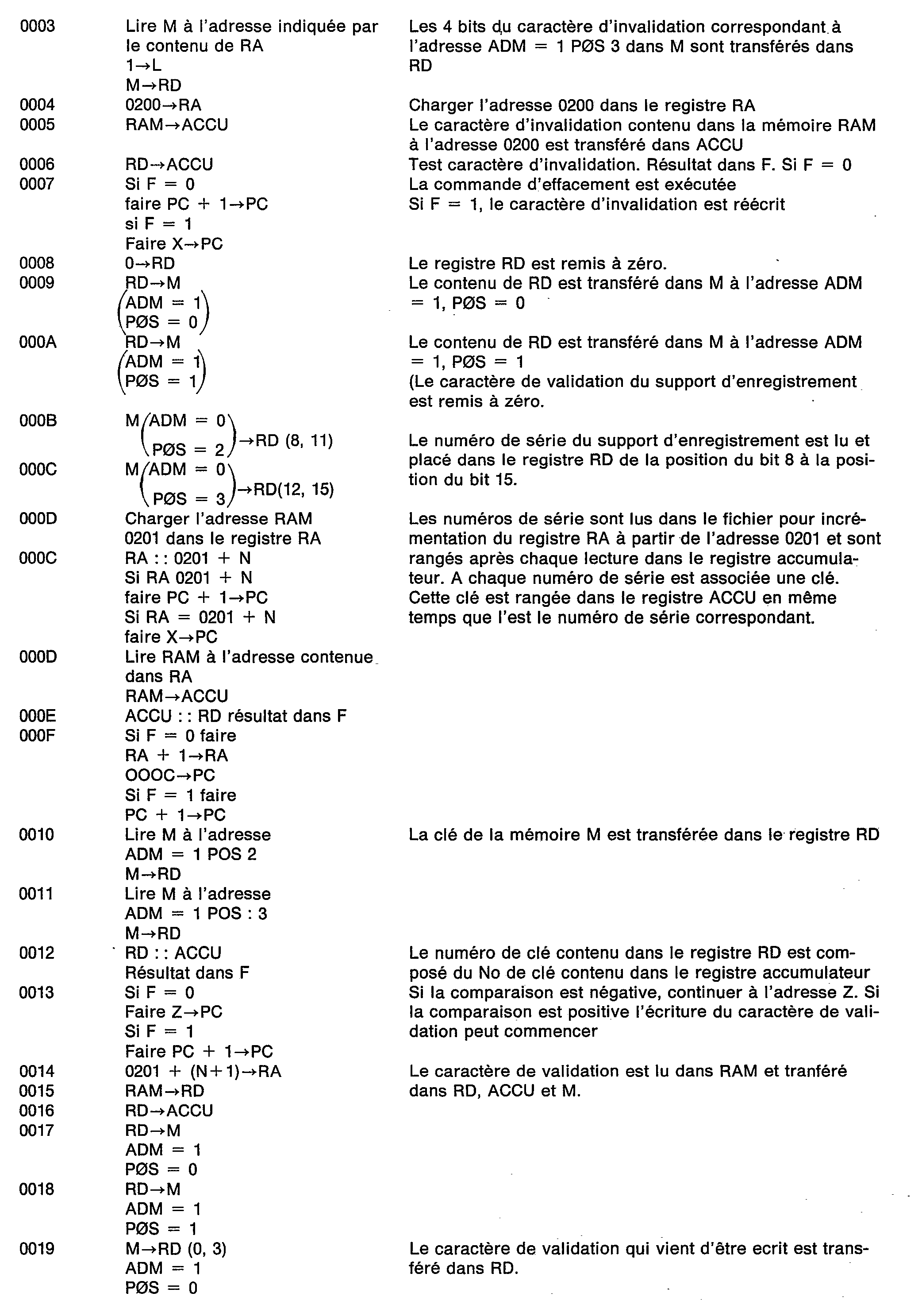
- the list of microinstructions identified by the state of the ordinal counter PC 20 is as follows:
- Fig. 6 is an alternative embodiment of the recycling machine shown in FIG. 1 in which the control elements of the recycling operation are located inside the recording medium.
- the microprocessor 7, the PROM memory 8 and the data memory M 10 are found incorporated on the same support.
- the memory control means M are integrated into the information medium.
- a monolithic structure will be given to all of the electronic elements incorporated in said support in order to make it impossible to test the signals passing between the memory 10, the microprocessor 7 and the PROM memory 8.
- the recycling machine 1 mainly consists of the RAM memory 9 and of the elements necessary (not shown) for establishing the connections between the recording medium 2, the keyboard 5, the disc 3 and the reader. the authorization card 3.
Description
La présente invention concerne un procédé pour prolonger la validité d'une zone de travail de la mémoire d'un support d'enregistrement où les informations enregistrées accessibles de l'extérieur ne peuvent être modifiées que par une personne habilitée, ladite mémoire comprenant en plus une zone protégée où sont mémorisées des informations d'identification inaccessibles de l'extérieur ainsi qu'un dispositif pour sa mise en oeuvre.The present invention relates to a method for extending the validity of a working area of the memory of a recording medium where the recorded information accessible from the outside can only be modified by an authorized person, said memory further comprising a protected area where are stored identification information inaccessible from the outside as well as a device for its implementation.
Les mémoires non volatiles ont la propriété de conserver en permanence des informations qu'elles contiennent en l'absence d'alimentation électrique extérieure. Les bandes magnétiques, les mémoires à tores magnétiques, les mémoires à bulles, les mémoires à semi-conducteurs réalisées en technologie MNOS, abréviation du terme anglo-saxon «Métal Nitride Oxyde Silicium» constituent des mémoires non volatiles. Ces mémoires sont aussi effaçables par l'action d'organes électroniques externes à ces mémoires.Non-volatile memories have the property of permanently retaining the information they contain in the absence of an external power supply. The magnetic tapes, the memories with magnetic cores, the memories with bubbles, the memories with semiconductors carried out in technology MNOS, abbreviation of the Anglo-Saxon term "Metal Nitride Oxide Silicon" constitute non volatile memories. These memories are also erasable by the action of electronic organs external to these memories.
Toutes les mémoires peuvent contenir un nombre maximum d'informations qui dépend du nombre des cellules élémentaires qu'elles contiennent et qui définissent leur capacité.All the memories can contain a maximum number of information which depends on the number of elementary cells which they contain and which define their capacity.
La capacité d'une mémoire non volatile limite donc dans le temps son utilisation. Lorsque le nombre d'informations mémorisées atteint la capacité utile de la mémoire, deux solutions s'offrent à l'utilisateur de la mémoire.The capacity of a non-volatile memory therefore limits its use over time. When the number of stored information reaches the useful capacity of the memory, two solutions are available to the memory user.
Il peut s'en déssaisir et en prendre une autre, vide d'informations. Il peut aussi songer à effacer (vider) le contenu de la partie utilisée lors de l'usage du support d'information de façon à rendre disponible la mémoire pour une autre utilisation.He can take it off and take another one, empty of information. He can also consider erasing (emptying) the content of the part used when using the information medium so as to make the memory available for another use.
La première solution est notamment exposée dans le document DE-A 2 738 113 où la carte possède une mémoire divisée en plusieurs sections qui sont successivement ouvertes au fur et à mesure qu'une section est pleine. Ces ouvertures se font sous le contrôle d'une personne habilitée. Cependant, lorsque toutes les sections de la mémoire sont pleines, la carte devient inutilisable, c'est-à-dire qu'il n'est procédé à aucun effacement ou remise à zéro de la mémoire qui puisse permettre une réutilisation de la carte.The first solution is explained in particular in
Une telle solution est chère et il est souhaitable de pouvoir effacer les informations enregistrées dans la mémoire pour réutiliser la carte. Cependant, dans certaines applications, type carte de crédit, il est impératif qu'en cours d'utilisation, les informations déjà mémorisées ne puissent être altérées, ce qui retirerait toute crédibilité aux dispositifs utilisant de tels supports d'enregistrement. Dans ces applications, les détenteurs de ces mémoires ne peuvent modifier ou même effacer les informations déjà mémorisées.Such a solution is expensive and it is desirable to be able to erase the information recorded in the memory to reuse the card. However, in certain applications, such as a credit card, it is imperative that during use, the information already stored cannot be altered, which would remove any credibility from the devices using such recording media. In these applications, the holders of these memories cannot modify or even erase the information already memorized.
Le but de l'invention est donc de réaliser un dispositif qui permette l'effacement des mémoires non volatiles du type précité seulement dans certaines conditions, en privant les titulaires des supports d'enregistrement munis desdites mémoires de toute possibilité leur permettant de procéder eux-mêmes à cet effacement.The object of the invention is therefore to produce a device which allows the erasure of non-volatile memories of the aforementioned type only under certain conditions, by depriving the holders of the recording media provided with said memories of any possibility allowing them to proceed themselves. same to this erasure.
Selon l'invention, l'effacement des mémoires composant les supports d'enregistrement ne pourra avoir lieu que dans un service privé ou administratif accrédité à le faire.According to the invention, the erasing of the memories making up the recording media can only take place in a private or administrative service accredited to do so.
Ceci suppose naturellement que des précautions soient prises au niveau des supports d'enregistrement eux-mêmes, de façon à dissuader les porteurs peu scrupuleux de ces supports d'enregistrement d'en altérer le contenu.This naturally presupposes that precautions are taken at the level of the recording media themselves, so as to dissuade the unscrupulous carriers of these recording media from altering the content thereof.
On sait en effet que les mémoires monolithiques non volatiles et effaçables sont pour la plupart réalisées à l'aide de semi-conducteurs sensibles à certaines perturbations physiques externes. L'exposition de ces mémoires à des rayonnements électromagnétiques notamment les ultraviolets, peut modifier la grandeur des charges électriques réparties, modifiant ainsi la nature des informations stockées.We know that the non-volatile and erasable monolithic memories are for the most part produced using semiconductors sensitive to certain external physical disturbances. The exposure of these memories to electromagnetic radiation, in particular ultraviolet radiation, can modify the magnitude of the distributed electrical charges, thus modifying the nature of the information stored.
Ainsi pour une information mémorisée sous la forme d'un mot à M éléments binaires et comprenant N éléments binaires dans l'état 1 et les M-N restant dans l'état 0, l'exposition à un rayonnement peut modifier l'état des éléments binaires constituant cette information, si bien qu'il peut en résulter un mot binaire modifié dans lequel N + q éléments binaires se retrouvent dans l'état 1 et les M - (N + q) restants se retrouvent dans l'état 0.Thus, for information stored in the form of a word with M binary elements and comprising N binary elements in
Des accès répétés diminuent progressivement les quantités d'éléctricité stockées. Des défauts des générateurs de courant ou de tension alimentant ces mémoires peuvent perturber et modifier les informations mémorisées.Repeated access progressively decreases the quantities of electricity stored. Faults in the current or voltage generators supplying these memories can disturb and modify the stored information.
Plusieurs dispositifs peuvent être mis en oeuvre pour garder l'intégrité des informations mémorisées. Il est possible de disposer des écrans d'absorption entre les mémoires et les sources de rayonnement, de créer des cycles de régénération des charges électriques stockées, de prévoir des dispositifs de sécurité au niveau des alimentations en énergie électrique ou de réserver une zone de la mémoire à l'inscription d'un caractère témoin avertissant par sont état que la mémoire ' a été exposée à des perturbations physiques extérieures. Un dispositif de mémorisation contenant un caractère témoin est décrit dans les demandes de brevet européennes publiées par les documents EP-A-0 013 523 et EP-A-0 016 295. L'introduction d'un caractère témoin dans les mémoires non volatiles effaçables rend l'utilisation de ces mémoires aussi sûre que celle obtenue avec des mémoires dont la technologie rend l'écriture irréversible. Les mémoires à diode semiconductrice sont des mémoires irréversibles, car la mémorisation d'un élément d'information s'effectue en claquant la jonction séparant les zones semiconductrices N & P constituant une diode.Several devices can be implemented to keep the integrity of the information stored. It is possible to have absorption screens between the memories and the radiation sources, to create regeneration cycles of the stored electrical charges, to provide safety devices at the level of the electrical energy supplies or to reserve a zone of the memory at the writing of a witness character warning by its state that the memory has been exposed to external physical disturbances. A storage device containing a witness character is described in the European patent applications published by documents EP-A-0 013 523 and EP-A-0 016 295. The introduction of a witness character in non-volatile erasable memories makes the use of these memories as safe as that obtained with memories whose technology makes writing irreversible. The semiconductor diode memories are irreversible memories, because the memorization of an information element is carried out by snapping the junction separating the N & P semiconductor zones constituting a diode.
Le procédé et le dispositif selon l'invention doivent être aptes à fonctionner avec des supports d'enregistrement munis des sécurités précitées et doit rendre inefficace les manipulations frauduleuses au niveau de la mémoire du support d'enregistrement. L'effacement du support d'enregistrement par le dispositif de l'invention n'aura lieu que par l'action d'une personne habilitée pour introduire dans le dispositif d'effacement les informations nécessaires à se mise en service. Ces informations sont comparées à l'intérieur du dispositif à des informations correspondantes mémorisées à l'intérieur de la mémoire du support d'enregistrement pour révéler au dispositif la véritable identité des supports d'enregistrement. L'identité dudit support sera constituée soit à l'aide d'un numéro de série qui lui sera attribué lors de sa fabrication, ou bien à l'aide d'une clé d'identification qu'il aura reçue lors de sa délivrance à son titulaire et par un carctère de validation qui permettra de reconnaître que toutes les données situées à l'intérieur du support d'enregistrement sont crédibles ou encore par l'ensemble de ces deux possibilités.The method and the device according to the invention must be able to operate with recording media provided with the aforementioned security devices and must make fraudulent manipulation ineffective in the memory of the recording medium. The erasure of the recording medium by the device of the invention will not take place only by the action of a person authorized to introduce into the erasure device the information necessary to be put into service. This information is compared inside the device to corresponding information stored inside the memory of the recording medium to reveal to the device the true identity of the recording media. The identity of said support will be established either using a serial number which will be assigned to it during its manufacture, or using an identification key which it will have received when it was delivered to its holder and by a validation character that will recognize that all the data located inside the recording medium is credible or by all of these two possibilities.
Pour atteindre ces objectifs, le procédé cité dans le premier alinéa consiste à
- - préenregistrer une clé de revalidation confidentielle dans la dite zone protégée avant la première mise en circulation du support, lors de la programmation initiale,
- - à connecter le support d'enregistrement à un dispositif de revalidation mis en service par une personne dûment habilitée autre que la personne qui détient le support,
- - à faire rentrer de l'extérieur une clé de revalidation,
- - à comparer cette clé de revalidation avec la clé préenregistrée dans le support, et
- - à valider l'opération de revalidation de la mémoire si les deux clés précitées sont identiques ou à invalider définitivement le support si ces deux clés sont différentes, ce qui correspond essentiellement au procédé d'après DE-A-2 738 113 et il est caractérisé en ce que la clé de revalidation est une clé d'effacement et que la revalidation consiste à effacer le contenu de la zone de travail, la rendant ainsi réutilisable.
- - pre-register a confidential revalidation key in the said protected area before the first circulation of the medium, during the initial programming,
- - to connect the recording medium to a revalidation device put into service by a duly authorized person other than the person who holds the medium,
- - to bring in a revalidation key from outside,
- - compare this revalidation key with the key prerecorded in the medium, and
- - to validate the memory revalidation operation if the two aforementioned keys are identical or to definitively invalidate the medium if these two keys are different, which essentially corresponds to the process according to DE-A-2 738 113 and it is characterized in that the revalidation key is an erasure key and that the revalidation consists in erasing the content of the work area, thus making it reusable.
Le dispositif pour la mise en oeuvre du procédé tel que défini pour effacer les informations écrites dans une zone de travail d'une mémoire d'un support d'enregistrement, ladite mémoire comprenant en plus une zone protégée où sont mémorisés une clé d'effacement inaccessible de l'extérieur et un numéro d'identification du support est caractérisé en ce qu'il comprend une mémoire où sont enregistrés plusieurs numéros d'identification et les clés d'effacement associées, des circuits de traitement pour lire le numéro d'identification du support à traiter, pour rechercher dans la mémoire la clé d'effacement associée, et à comparer cette clé avec celle préalablement enregistrée dans le support.The device for implementing the method as defined for erasing the information written in a working area of a memory of a recording medium, said memory further comprising a protected area where an erasing key is stored inaccessible from the outside and an identification number of the support is characterized in that it comprises a memory in which several identification numbers and the associated erasure keys are recorded, processing circuits for reading the identification number of the medium to be processed, to search the memory for the associated erasure key, and to compare this key with that previously recorded in the medium.
Comme de cette façon on incorpore dans ledit support les moyens de commande et d'adressage de la mémoire on assure ainsi l'inviolabilité des informations contenues dans la mémoire du support d'enregistrement.As in this way, the memory control and addressing means are incorporated into said medium, thus ensuring the inviolability of the information contained in the memory of the recording medium.
Sans cette précaution, une personne peu scrupuleuse pourrait, par simple observation des signaux échangés entre la machine de recyclage et la mémoire du support d'enregistrement, connaître la nature des informations mémorisées, le scénario nécessaire pour réaliser l'effacement de ces informations et le code de validation du support pour un nouvel usage.Without this precaution, an unscrupulous person could, by simple observation of the signals exchanged between the recycling machine and the memory of the recording medium, know the nature of the information stored, the scenario necessary to erase this information and the support validation code for a new use.
L'incorporation des moyens de commande audit support constitue alors un obstacle physique infranchissable car dans ce cas, les opérations séquentielles de commande se déroulent entièrement à l'intérieur du support d'enregistrement sans que le milieu extérieur puisse en avoir connaissance ou puisse en découvrir le secret. Dans ce cas, le test interne de la validité de la clé pour donner l'ordre d'effacement, entraînera s'il est négatif une altération par les moyens de commande précités de la zone du caractère d'invalidation qui ne pourra jamais revenir à son état d'origine et par conséquent interdira tout usage ultérieur du support d'enregistrement. Les moyens de commande incorporés au support d'enregistrement interdiront par contrôle de ce caractère tout usage du support d'enregistrement. Ainsi les moyens entrant dans la composition du dispositif pour l'effacement d'informations mémorisées à l'intérieur du support d'enregistrement se retrouvent incorporés audit support.The incorporation of the control means into said support then constitutes an insurmountable physical obstacle because in this case, the sequential control operations take place entirely inside the recording medium without the outside environment being able to know or to be able to discover it. the secret. In this case, the internal test of the validity of the key to give the erasure order, will cause if it is negative an alteration by the aforementioned control means of the zone of the invalidating character which can never return to its original condition and therefore will prohibit any further use of the recording medium. The control means incorporated in the recording medium will prohibit, by controlling this character, any use of the recording medium. Thus the means used in the composition of the device for erasing information stored inside the recording medium are incorporated into said medium.
La fig. 1 est une représentation simplifiée du dispositif de réutilisation ou de recyclage de support d'enregistrement selon l'invention.Fig. 1 is a simplified representation of the device for reusing or recycling the recording medium according to the invention.
La fig. 2 montre un mode de réalisation de la machine de recyclage représentée à la fig. 1 et de ses liaisons avec d'autres éléments nécessaires à son fonctionnement.Fig. 2 shows an embodiment of the recycling machine shown in FIG. 1 and its connections with other elements necessary for its operation.
La fig. 3 est une représentation d'un quadrillage de l'espace mémoire d'un support d'enregistrement.Fig. 3 is a representation of a grid of the memory space of a recording medium.
La fig. 4 est une représentation détaillée des moyens de commandes utilisés pour commander l'opération de recyclage et entrant dans la composition du dispositif de recyclage selon l'invention.Fig. 4 is a detailed representation of the control means used to control the recycling operation and forming part of the composition of the recycling device according to the invention.
La fig. 5 est un diagramme montrant les différentes opérations exécutées par la machine de recyclage et les moyens de commande pour effacer un support d'enregistrement et le rendre apte à un autre usage.Fig. 5 is a diagram showing the various operations performed by the recycling machine and the control means for erasing a recording medium and making it suitable for another use.
La fig. 6 est une variante de réalisation de la machine de recyclage représentée à la fig. 1 dans laquelle les éléments de commande de l'opération de recyclage et entrant dans la composition du dispositif de recyclage se trouvent situés à l'intérieur du support d'enregistrement.Fig. 6 is an alternative embodiment of the recycling machine shown in FIG. 1 in which the elements for controlling the recycling operation and forming part of the composition of the recycling device are located inside the recording medium.
Le dispositif représenté à la fig. 1 se compose d'une machine de recyclage coopérant d'une part avec le support d'enregistrement 2 à effacer et à valider pour d'autres usages et d'autre part avec un fichier 3 permettant de vérifier l'identité du support d'enregistrement à effacer et d'une carte d'habilitation 4 appartenant à l'opérateur accrédité pour effectuer l'opération de recyclage et dans laquelle se trouve enregistré un code d'identification.The device shown in fig. 1 consists of a recycling machine cooperating on the one hand with the
Dans le fichier 3 se trouvent consignés les numéros de série de tous les supports d'enregistrement qui ont été fabriqués par l'organisme émetteur desdits supports.In
A chaque numéro de série correspond un support d'enregistrement qui, lorsqu'il est remis à sont détenteur par l'organisme accrédité reçoit un autre code d'identification ou clé. Ainsi, à chaque numéro de série correspond une clé. Une représentation de la correspondance clé numéro de série est consignée dans le fichier 3.Each serial number corresponds to a recording medium which, when given to are holder by the accredited body receives another identification code or key. Thus, each serial number corresponds to a key. A representation of the key serial number correspondence is recorded in
Le fichier 3 pourra être conservé sur n'importe quel support d'enregistrement, bandes magnétiques ou disques magnétiques comme cela est représenté à la fig. 2. L'opération de recyclage pourra commencer lorsque le dispositif aura vérifié que l'opérateur est bien accrédité. Pour cela, l'opérateur devra introduire dans le dispositif une carte d'habilitation contenant le code d'identification de l'opérateur et simultanément frapper son code d'identification ou mot de passe sur un clavier.
Si la relation entre le code d'identification de la carte et le mot de passe frappé sur le clavier est correcte, la carte d'habilitation communiquera à la machine où son utilisation est prévue les informations nécessaires au recyclage. Dans une version simplifiée la carte d'habilitation pourra être constituée d'une simple carte magnétique ou d'une mémoire à semi-conducteurs du type ROM ou PROM abréviations des termes anglo-saxons «Read Only Memory» ou «Programmable Read Only Memory». Dans une version plus complexe, on pourra adjoindre à la carte d'habilitation des moyens de commande programmés.If the relationship between the card identification code and the password typed on the keyboard is correct, the authorization card will communicate to the machine where its use is intended the information necessary for recycling. In a simplified version, the authorization card can be made up of a simple magnetic card or a semiconductor memory of the ROM or PROM type, abbreviations of the English words "Read Only Memory" or "Programmable Read Only Memory" . In a more complex version, it will be possible to add programmed control means to the authorization card.
La vérification des identités à la fois de l'opérateur et du code du support d'enregistrement à effacer, de même que l'opération d'effacement proprement dite et de validation du support d'enregistrement pour de nouveaux usages nécessitent l'exécution d'une suite d'opérations entre la machine de recyclage et le support d'enregistrement. Cette suite d'opérations pourra être exécutée séquentiellement à l'aide de circuits logiques électroniques séquentiels ou à l'aide d'une structure banalisée comme l'est celle des microprocesseurs actuels auxquels sera adjoint un programme d'exploitation. Dans cette deuxième solution, il sera possible d'utiliser le microprocesseur 8080 commercialisé par la Société des Etats Unis d'amérique «INTEL». Un exemple de réalisation de la machine de recyclage à l'aide d'un microprocesseur est montré à la fig. 2.The verification of the identities of both the operator and the code of the recording medium to be erased, as well as the actual erasing operation and validation of the recording medium for new uses require the execution of '' a series of operations between the recycling machine and the recording medium. This sequence of operations can be executed sequentially using sequential electronic logic circuits or using an unmarked structure like that of current microprocessors to which an operating program will be added. In this second solution, it will be possible to use the 8080 microprocessor marketed by the Company of the United States of America "INTEL". An exemplary embodiment of the recycling machine using a microprocessor is shown in FIG. 2.
Un mode particulier de réalisation de la machine de recyclage est montré en 1 sur la fig. 2. Elle comprend un microprocesseur 7 auquel est adjoint deux mémoires, une mémoire morte PROM 8 et une mémoire vive RAM 9. On sait qu'une mémoire vive a la propriété d'être effaçable et qu'il est possible de lire et de récrire tout ou partie des informations qui y sont contenues. Par contre, une mémoire morte n'est pas effaçable et seule la lecture des informations qui y sont mémorisées est possible. Le BUSD ou encore la ligne de donnée D véhicule les données ou informations transmises entre le microprocesseur 7, la mémoire PROM 8, la mémoire RAM 9 et les organes externes reliés à la machine de recyclage. Les organes externes sont le support d'enregistrement à recycler 2, l'unité de disque magnétique 3, le clavier d'introduction du mot de passe 5, le lecteur de carte 6 dans lequel est introduit la carte d'habilitation de l'opérateur 4.A particular embodiment of the recycling machine is shown at 1 in FIG. 2. It comprises a
Les mémoires PROM, RAM 9 ainsi que la mémoire M du support d'enregistrement à recycler sont adressées à partir du microprocesseur 7 par le BUS A ou ligne d'adresse A. Le microprocesseur 7 envoie les diverses commandes des organes externes pour la liaison Co, décomposée elle-même en C,, C2, C3 et C, sur la fig. 2.The PROM,
La fig. 3 représente l'organisation des zones de la mémoire M 10 du support d'enregistrement à recycler 2. Cette mémoire est une mémoire non volatile effaçable qui sera réalisée de préférence en technologie MOS (Metal Oxyde Semi Conducteur) afin que les informations mémorisées puissent être conservées très longtemps (des années) sans être altérées tout en pouvant être effacées en tout ou partie à n'importe quel instant. La mémoire représentée contient 300 mots de 4 bits chacun. On rappelle ici que le mot bit sert à désigner la plus petite quantité d'informations qui, exprimée dans un langage binaire, ne peut prendre que deux états 0 ou 1. L'adressage de cette mémoire se fait par mots et dans l'exemple représenté, la mémoire a une organisation matricielle de 76 lignes et 4 colonnes. Un mot se trouve à l'intersection d'une ligne et d'une colonne. Les emplacements des mots de la mémoire sont repérés par un numéro de 0 à 299. A la ligne 0 correspond les mots 0 à 3 à la ligne 1 les mots 4 à 7, etc.... à la ligne 75 les mots 296 à 299. L'adressage d'un mot mémoire est effectué en déposant un mot d'adresse à 9 bits sur le BUS A représentant 512 adresses possibles bien que 300 ici soient utiles.Fig. 3 represents the organization of the areas of the
Les 2 bits de poids les plus faibles sont utilisés pour l'adressage des colonnes 0 à 3 de la mémoire alors que les 7 autres bits sont utilisés à l'adressage des lignes. Les 2 bits d'adressage des colonnes sont décodés par le décodeur de position D POS 12, les 7 bits d'adressage des lignes sont décodés par le décodeur d'adresse D ADM 11. Le code d'adressage utilisé est le code binaire naturel. Un emplacement mémoire ainsi adressé peut être lu ou écrit. Lorsqu'il est lu, une commande de lecture 2 positionne les circuits de lecture de la mémoire et le contenu de l'emplacement adressé de la mémoire est placé dans le registre de données RD. Lorsqu'il est écrit, une commande d'écriture E positionne les circuits d'écriture de la mémoire et les données à écrire sont dans un premier temps placées sur le BUS D pour être transférées dans le registre RD 13 puis dans un deuxième temps transférées à l'emplacement adressé de la mémoire. Le registre RD a une longueur de 16 bits, il peut donc contenir 4 mots. Les emplacements RD (0 à 3) du registre RD sont destinés à recevoir les mots de la colonne 0 de la mémoire, de même les emplacements RD (4, 7) reçoivent les mots de la colonne 1, RD (8 à 11) reçoivent les mots de la colonne 3 et RD (12 à 15) reçoivent les mots de la colonne 3. Il est rappelé ici que les BUSA et D sont reliés au microprocesseur 7 de la fig. 2.The 2 least significant bits are used for addressing
La mémoire est organisée en deux zones. La zone 1 contient tous les attributs du support d'enregistrement nécessaires à sont identification que ce soit pendant sont utilisation pour le service auquel le support est normalement destiné ou pendant l'opération de recyclage. La zone 2 est une zone de travail réservée au stockage des informations recueillies pendant l'usage normal de support d'enregistrement. Durant l'opération de recyclage toutes les informations présentes dans la zone 2 devront être effacées. La zone 1 est partagée en quatre espaces. Le premier espace adressé par ADMO, POS = 0 et POS = 1 est réservé à la mémorisation d'un caractère témoin, le contenu de cet espace sera contrôlé pendant les usages multiples du support d'enregistrement pour vérifier que la mémoire n'a pas été perturbée par des phénomènes physiques externes comme cela est expliqué dans les demandes de brevet précédemment citées. Le deuxième espace adressé par ADM = 0, POS = 2 et 3 est réservé à la mémorisation d'un numéro de série que le support d'enregistrement reçoit au cours de sa fabrication. Le troisième espace adressé par ADM = 1 POS = 0 et 1 est réservé au caractère de validation du support d'enregistrement. Ce caractère est inscrit lorsque tous les attributs du support permettant son identification sont corrects, son inscription a lieu avant la délivrance du support d'enregistrement à son titulaire. Le quatrième espace est réservé à la mémorisation du caractère clé du support d'enregistrement, il est adressé pour ADM = 1 POS = 2 et 3. Si au cours de l'utilisation d'un support d'enregistrement le caractère clé se trouve modifié et ne correspond plus au caractère clé mis en circulation par l'organisme émetteur du support d'enregistrement, le caractère d'invalidation sera inscrit dans une autre zone de la mémoire ou à la place du caractère clé comme cela est représenté sur la fig. 3.The memory is organized into two areas.
Le caractère clé sera représenté de préférence avec un code composé de M bits comprenant un nombre N prédéterminé de bits à 1 ou à 0 (code M par N). Avec cette précaution supplémentaire, il sera possible au dispositif de détecter qu'une tentative d'effacement a eu lieu, puisque dans ce cas une nouvelle configuration binaire inscrite dans cet emplacement ne vérifiera plus la règle ccM parmi N» +.The key character will preferably be represented with a code composed of M bits comprising a predetermined number N of bits at 1 or at 0 (code M by N). With this additional precaution, it will be possible for the device to detect that an erasure attempt has taken place, since in this case a new binary configuration registered in this location will no longer verify the ccM rule among N »+.
La même règle pourra être adoptée pour le caractère de validation, si le caractère de validation a été écrit dans un code M parmi N et si M représente le nombre de bits il suffira d'ajouter un bit 1 supplémentaire au caractère de valisation pour le rendre invalide. Il pourra lors de l'opération de recyclage revenir à sa forme originelle. The same rule could be adopted for the validation character, if the validation character was written in an M code among N and if M represents the number of bits, it will suffice to add an
La fig. 4 est une représentation détaillée des moyens de commande utilisés pour commander l'opération de recyclage. Ces moyens de commande étant constitués par le microprocesseur.Fig. 4 is a detailed representation of the control means used to control the recycling operation. These control means being constituted by the microprocessor.
Ce microprocesseur comprend un bus de données, un bus d'adresses et un bus de commandes, une unité arithmétique logique 14, un registre accumulateur 15, un registre de mémorisation de résultats d'opération SR 14, un registre d'adresse RA 17, un registre d'instructions RI18, un décodeur d'instruction 19, un compteur ordinal (pro- gram compteur) 20, un registre de sauvegarde SP21, des registres d'entrée/sortie de données 1023 et IB 24. Un opérande placé sur le bus D est transmis à l'entrée 1 de l'unité arithmétique logique ALU14 par la liaison d4, le deuxième opérande est pris dans le registre accumulateur ACCU15 et est transmis sur l'entrée 2 de l'unité 2 de l'unité arithmétique logique ALU15, le résultat du calcul effectué entre ces deux opérandes peut être transmis dans le registre SR 16 ou dans le registre accumulateur 15 par les liaison d7, d9, BUS D et d5. Le registre SR 16 mémorise les bits d'état C, S, F qui sont des résultats de calcul et qui permettent des opérations de branchement vers d'autres sous programmes.This microprocessor comprises a data bus, an address bus and a command bus, a
Une instruction placée sur le bus D est transmise dans le registre Ri 18 par la liaison D1.An instruction placed on the bus D is transmitted in the
Le registre RI contient essentiellement deux emplacements, un réservé à la mémorisation du code opération de l'instruction (COP), l'autre à son adresse. Le code opération est transmis au décodeur d'instruction 19 pour la ligne d3, qui transmet sur la ligne C4 puis sur le bus C les commandes nécessaires à l'exécution de l'instruction. La partie adresse de l'instruction est transmise pour la ligne d2 sur le BUS D. Le registre RA contient l'adresse de la donnée ou de l'information recherchée dans le dispositif de recyclage, cette adresse peut être dans l'une des deux mémoires PROM 8 et RAM 9 ou dans le support d'enregistrement 2, elle est transmise sur le BUS A par la liaison a,. Le compteur ordinal PC 20 est chargé à partir du BUS D par l'intermédiaire de la ligne d10, la sortie 2 est reliée à l'entrée du registre SP21 dont la sortie 2 est reliée par la ligne d12 au bus de données BUS D. La sortie 2 du compteur 20 est aussi reliée par la ligne a2 au bus d'adresse BUS A. Le contenu du compteur ordinal 20 peut être incrémenté d'une unité à partir d'une horloge non représentée. Les registres 10 22 et IB 23 ont leurs entrées/sorties toutes deux reliées au BUS D et servent de registre tampon. Les programmes et microprogrammes contenus dans les mémoires 8, 9 ou 10 pourraient donc être adressés indifféremment par le compteur ordinal PC 20 ou par le registre RA 17.The register RI essentially contains two locations, one reserved for storing the instruction operation code (COP), the other at its address. The operation code is transmitted to the
Les informations lues aux emplacements adressés de ces mémoires seront transférées sur le BUS D dans le registre d'instruction Rt18, s'il s'agit d'instruction, ou transférées à l'entrée 1 de l'unité arithmétique logique ou dans le registre accumulateur 15 ou dans le registre 10 22 s'il s'agit de données. Ces transferts auront lieu en fonction du type d'instruction utilisé. Les informations à écrire dans les emplacements des mémoires adressées par l'information d'adresse présentée sur le BUS A seront transférées sur le BUS D par l'intermédiaire du registre tampon IB 23. Le BUS D sera aussi utilisé pour transférer des données ou des informations entre registres. La partie adresse de l'instruction contenue dans le registre RI pourra être transférée d'un sous programme ou microprogramme dont le déroulement est nécessaire pour exécuter l'instruction.The information read at the addressed locations of these memories will be transferred to BUS D in the instruction register Rt18, if it is an instruction, or transferred to input 1 of the logical arithmetic unit or in the
Le résultat d'une opération obtenu sur deux opérandes pourra être rangé dans le registre accumulateur 15, dans la mémoire vive RAM 9 dans le registre RD du support d'enregistrement 2 ou dans le registre IB en vue de son transfert par exemple vers l'unité de disque 3.The result of an operation obtained on two operands can be stored in the
Le dispositif qui vient d'être décrit permet donc d'exécuter séquentiellement les opérations nécessaires au recyclage des supports d'enregistrement. Ces opérations nécessitent l'exécution par les moyens de commande d'un programme d'en- trée/sortie pour exécuter le transfert des informations de la mémoire à disque 3 dans la mémoire RAM 9 de la fig. 2. Le disque 3 contient comme il a été dit précédemment le fichier de correspondance des clés et numéro de série des supports d'enregistrement en circulation. Au moment de l'initialisation du dispositif, les informations mémorisées sur le disque (instruction et fichier sont transférées dans la mémoire vive RAM 9). Cette opération d'entrée/sortie de transfert de données d'un disque dans la mémoire vive RAM 9 est une opération très classique qui est similaire à celle rencontrée dans tous les systèmes de traitement de données. L'homme de l'art pourra se reporter utilisement au livre de RODNAY ZAKS et PIERRE LE BEUX, intitulé «les microprocesseurs» édité par SYBEX - 313, rue Lecourbe - 75015 PARIS, dans lequel ces types de transferts sont décrits.The device which has just been described therefore makes it possible to execute sequentially the operations necessary for recycling the recording media. These operations require the execution by the control means of an input / output program to execute the transfer of information from the
Ces opérations de transfert étant terminés, l'opération de recyclage proprement dite est engagée conformément à l'organigramme représenté à la fig. 5.These transfer operations being completed, the actual recycling operation is initiated in accordance with the flowchart shown in fig. 5.
A l'étape 51, le caractère d'invalidation mémorisé sur le support d'enregistrement est testé; si ce test est positif, le support d'enregistrement est rendu inutilisable. Si le test est négatif, le caractère de validation du support d'enregistrement est effacé (étape 53). Le caractère d'invalidation du support d'enregistrement ayant été testé à l'étape 51, l'étape 54 consiste à lire le numéro de série du support d'enregistrement afin d'obtenir la clé associée par l'intermédiaire du fichier de la machine de recyclage. Par les moyens de commande une comparaison est faite entre la clé ainsi recherchée et la clé contenue dans le support d'enregistrement (étape 54 et 55). Si le rest est correct un caractère de validation est écrit dans le support d'enregistrement (étape 56). Le dispositif vérifie à l'étape 57 que ce caractère a été correctement écrit, si tel est le cas, l'opération d'effacement des autres zones de la mémoire du support d'enregistrement est effectuée (étape 58). Si les tests effectués aux étapes 51 et 55 s'avèrent incorrects, le support d'information est définitivement mis hors d'usage par écriture d'un caractère d'invalidation (étape 59). Toutes autres tentatives de recyclage seront par la suite infructueuses car les moyens de commande en lisant la clé du support d'enregistrement à l'étape 51 détecteront une clé fausse qui empêchera la poursuite des opérations 52 à 58. Si le test du caractère de validation de l'étape 57 s'avère incorrect, le dispositif n'entamera pas l'effacement des autres zones de la mémoire et reprendra les étapes 51 à 57 jusqu'à ce que l'écriture du caractère' de validation s'avère fructueuse. Pour éviter un nombre répété d'écritures infructueuses du caractère de validation on pourra limiter le nombre des essais infructueux par exemple à 10. On observera la symétrie des opérations associées au déroulement normal (étape 56 à 57) avec le déroulement des opérations associées à une erreur (étape 59 à 60) où l'étape 60 consiste à tester le caractère d'invalidation de façon à réaliser une symétrie de fonctionnement du microprocesseur et à tester que le caractère a bien été écrit. Cette symétrie rend inefficace tous essais d'observation des signaux sur les lignes de transmission ou d'alimentation en vue d'empêcher le positionnement du caractère d'invalidation. La suite des opérations qui vient d'être indiquée pourra être exécutée à l'aide d'un microprogramme inscrit dans la mémoire PROM 8.In
A début de l'opération du recyclage, le registre d'instruction RI 18 contient l'adresse de début du microprogramme dans la mémoire PROM 8. Cette adresse est transférée dans le compteur ordinal PC 20. La progression du compteur ordinal PC 20 d'une unité à partir de l'adresse de début du microprogramme permettra l'exécution nécessaire des microinstructions correspondant à ce microprogramme. Les microinstructions seront successivement chargées dans le registre d'instructions RI 18. Elles contiennent un code opération spécifiant le type d'opération à effectuer et une partie adresse spécifiant l'emplacement dans le dispositif où se trouve la donnée ou l'opérande sur lequel une opération spécifiée par le code opération doit s'effectuer. On suppose que l'adresse début du microprogramme de recyclage est située à l'adresse PROM = 0000. La liste des microinstructions repérée par l'état du compteur ordinal PC 20 est la suivante:


La fig. 6 est une variante de réalisation de la machine de recyclage représentée à la fig. 1 dans laquelle les éléments de commande de l'opération de recyclage se retrouvent situés à l'intérieur du support d'enregistrement. Dans ce mode de réalisation, le microprocesseur 7, la mémoire PROM 8 et la mémoire de données M 10 se retrouvent incorporés sur le même support. De cette façon, les moyens de commande de la mémoire M se trouvent intégrés au support d'informations. De préférence, il sera donné une structure monolithique à l'ensemble des éléments électroniques incorporés au dit support afin de rendre impossible des tests sur les signaux transitant entre la mémoire 10, le microprocesseur 7 et la mémoire PROM 8.Fig. 6 is an alternative embodiment of the recycling machine shown in FIG. 1 in which the control elements of the recycling operation are located inside the recording medium. In this embodiment, the
Dans ce mode de réalisation, la machine de recyclage 1 est constitué principalement de la mémoire RAM 9 et des éléments nécessaires (non représentés) pour établir les liaisons entre le support d'enregistrement 2, le clavier 5, le disque 3 et le lecteur de la carte d'habilitation 3.In this embodiment, the
L'exemple qui vient d'être donné d'une réalisation préférée de l'invention n'est nullement limitatif, il va de soi que tout homme de l'art bien au fait des techniques des systèmes de traitement de données pourra trouver d'autres modes de réalisation sans pour autant sortir du cadre même de l'invention.The example which has just been given of a preferred embodiment of the invention is in no way limiting, it goes without saying that any person skilled in the art well versed in the techniques of data processing systems will be able to find other embodiments without departing from the very scope of the invention.
Claims (12)
characterised in that the revalidation key is an erase key and that the revalidation consist in erasing the contents of the working zone thereby making the same reusable.
Applications Claiming Priority (2)
| Application Number | Priority Date | Filing Date | Title |
|---|---|---|---|
| FR7910561 | 1979-04-25 | ||
| FR7910561A FR2455320B1 (en) | 1979-04-25 | 1979-04-25 | DEVICE FOR RECYCLING IDENTIFIABLE RECORDING MEDIA USING IDENTIFICATION DATA AND NON-VOLATILE DELETE MONOLITHIC MEMORY COMPOUNDS |
Publications (2)
| Publication Number | Publication Date |
|---|---|
| EP0018889A1 EP0018889A1 (en) | 1980-11-12 |
| EP0018889B1 true EP0018889B1 (en) | 1985-09-04 |
Family
ID=9224748
Family Applications (1)
| Application Number | Title | Priority Date | Filing Date |
|---|---|---|---|
| EP80400547A Expired EP0018889B1 (en) | 1979-04-25 | 1980-04-22 | Process for prolonging the validity of the memory working zone of a data carrier |
Country Status (7)
| Country | Link |
|---|---|
| US (1) | US4442345A (en) |
| EP (1) | EP0018889B1 (en) |
| JP (1) | JPS5638650A (en) |
| BR (1) | BR8002518A (en) |
| CA (1) | CA1151298A (en) |
| DE (1) | DE3071055D1 (en) |
| FR (1) | FR2455320B1 (en) |
Families Citing this family (75)
| Publication number | Priority date | Publication date | Assignee | Title |
|---|---|---|---|---|
| US4568936A (en) * | 1980-06-23 | 1986-02-04 | Light Signatures, Inc. | Verification system for document substance and content |
| FR2503423A1 (en) * | 1981-03-31 | 1982-10-08 | Flonic Sa | Electronic memory for telephone prepaid transaction card - uses encoded memory to validate alteration of credit balance in on-card non-volatile memory |
| JPS58183568U (en) * | 1982-05-28 | 1983-12-07 | 大日本印刷株式会社 | recoding media |
| JPS58209000A (en) * | 1982-05-28 | 1983-12-05 | Dainippon Printing Co Ltd | Ic card |
| US4555591A (en) * | 1982-09-07 | 1985-11-26 | At&T Bell Laboratories | Integrated circuit devices for secure data encryption |
| JPS5971180A (en) * | 1982-10-16 | 1984-04-21 | Dainippon Printing Co Ltd | Information processing method in ic card |
| JPS5971195A (en) * | 1982-10-17 | 1984-04-21 | Dainippon Printing Co Ltd | Information processing method in ic card |
| JPS5977699A (en) * | 1982-10-25 | 1984-05-04 | Dainippon Printing Co Ltd | Integrated circuit card |
| JPS5998395A (en) * | 1982-11-29 | 1984-06-06 | Dainippon Printing Co Ltd | Ic card |
| US4525805A (en) * | 1982-12-20 | 1985-06-25 | Richard Prosan | Secure locking system employing radiant energy and electrical data transmission |
| DE3315047A1 (en) * | 1983-04-26 | 1984-10-31 | Siemens AG, 1000 Berlin und 8000 München | INTEGRATED CIRCUIT WITH AN APPLICATION MEMORY DESIGNED AS A NON-VOLATILE WRITE-READ MEMORY |
| DE3318083A1 (en) * | 1983-05-18 | 1984-11-22 | Siemens AG, 1000 Berlin und 8000 München | CIRCUIT ARRANGEMENT WITH A STORAGE AND ACCESS CONTROL UNIT |
| DE3318624A1 (en) * | 1983-05-21 | 1984-11-22 | Sachs Systemtechnik Gmbh, 8720 Schweinfurt | MAGNETICALLY CODED WARNING OR LOCKING SYSTEM WITH SERIAL CODE TRANSFER |
| JPS603082A (en) * | 1983-06-18 | 1985-01-09 | Dainippon Printing Co Ltd | Ic card |
| JPS603081A (en) * | 1983-06-18 | 1985-01-09 | Dainippon Printing Co Ltd | Ic card |
| JPS6084686A (en) * | 1983-10-17 | 1985-05-14 | Toshiba Corp | Recording system of information recording medium |
| JPS60140597A (en) * | 1983-12-28 | 1985-07-25 | Giichi Kuze | Eprom programmer |
| JPS60207964A (en) * | 1984-03-31 | 1985-10-19 | Toshiba Corp | Transaction system using portable medium |
| US4749982A (en) * | 1984-06-19 | 1988-06-07 | Casio Computer Co., Ltd. | Intelligent card |
| JPS6152775A (en) * | 1984-08-22 | 1986-03-15 | Omron Tateisi Electronics Co | Illegal access preventing system of card |
| US4918631A (en) * | 1984-09-07 | 1990-04-17 | Casio Computer Co., Ltd. | Compact type electronic information card |
| FR2575566B1 (en) * | 1984-12-28 | 1990-06-22 | Bull Sa | METHOD FOR CUSTOMIZING PORTABLE MEDIA SUCH AS CARDS |
| JPS61210488A (en) * | 1985-03-14 | 1986-09-18 | Toppan Moore Co Ltd | Ic card |
| JPH0682427B2 (en) * | 1985-03-22 | 1994-10-19 | サンデン株式会社 | vending machine |
| JPS61275948A (en) * | 1985-05-31 | 1986-12-06 | Casio Comput Co Ltd | Data storage device |
| FR2590051B1 (en) * | 1985-11-08 | 1991-05-17 | Eurotechnique Sa | CARD COMPRISING A COMPONENT AND MICROMODULE WITH SIDING CONTACTS |
| FR2590052B1 (en) * | 1985-11-08 | 1991-03-01 | Eurotechnique Sa | METHOD FOR RECYCLING A CARD COMPRISING A COMPONENT, CARD PROVIDED FOR RECYCLE |
| JPS62121979A (en) * | 1985-11-22 | 1987-06-03 | Mitsubishi Electric Corp | Integrated circuit memory |
| WO1987003691A1 (en) * | 1985-12-12 | 1987-06-18 | Dennison Manufacturing Company | Determination of test substances |
| JPS62147586A (en) * | 1985-12-23 | 1987-07-01 | Hitachi Ltd | Wrong preventing system |
| US4962459A (en) * | 1985-12-26 | 1990-10-09 | Mallozzi Joseph D | System for accounting for postage expended by a postage meter having data security during printing |
| JPS62146275U (en) * | 1986-03-04 | 1987-09-16 | ||
| US4874935A (en) * | 1986-03-10 | 1989-10-17 | Data Card Coprporation | Smart card apparatus and method of programming same |
| JPS62211756A (en) * | 1986-03-12 | 1987-09-17 | Casio Comput Co Ltd | Testing system for ic card |
| JPS62231395A (en) * | 1986-03-31 | 1987-10-09 | 松下冷機株式会社 | Sales memory for vending machine |
| US4742215A (en) * | 1986-05-07 | 1988-05-03 | Personal Computer Card Corporation | IC card system |
| JPH0758500B2 (en) * | 1987-02-20 | 1995-06-21 | 株式会社東芝 | Portable electronic device |
| KR910002448B1 (en) * | 1987-03-20 | 1991-04-22 | 가부시키가이샤 도시바 | Portabel electronic device |
| JP2776929B2 (en) * | 1989-03-29 | 1998-07-16 | 株式会社日立製作所 | Card data processing system and card data processing method |
| US4983820A (en) * | 1989-05-15 | 1991-01-08 | Dallas Semiconductor Corporation | Interface for receiving electronic tokens |
| JPH0426923Y2 (en) * | 1989-05-17 | 1992-06-29 | ||
| JPH0314083A (en) * | 1989-06-12 | 1991-01-22 | Toshiba Corp | Portable medium |
| JPH03208192A (en) * | 1990-01-09 | 1991-09-11 | Hitachi Maxell Ltd | Collected ic card using system |
| US5623547A (en) * | 1990-04-12 | 1997-04-22 | Jonhig Limited | Value transfer system |
| FR2665279A1 (en) * | 1990-07-24 | 1992-01-31 | Aschenbroich Yves | Process for protecting portable cards containing information in memory and device for its implementation |
| FR2666425A1 (en) * | 1990-08-31 | 1992-03-06 | Gemplus Card Int | METHOD AND DEVICE FOR UPDATING INFORMATION IN A MEMORY AND THEIR USE IN MEMORY CARDS. |
| FR2674647A1 (en) * | 1991-03-29 | 1992-10-02 | Widmer Michel | Apparatus forming an electronic cheque-book for financial transactions and process for using such an apparatus |
| JPH052536A (en) * | 1991-07-25 | 1993-01-08 | Dainippon Printing Co Ltd | Ic card |
| US5453601A (en) * | 1991-11-15 | 1995-09-26 | Citibank, N.A. | Electronic-monetary system |
| US5317636A (en) * | 1992-12-09 | 1994-05-31 | Arris, Inc. | Method and apparatus for securing credit card transactions |
| CH685891A5 (en) * | 1993-01-18 | 1995-10-31 | Ascom Autelca Ag | A method as security concept to prevent unauthorized use of a payment instrument for cashless settling on imprest |
| US5799087A (en) * | 1994-04-28 | 1998-08-25 | Citibank, N.A. | Electronic-monetary system |
| US5831827A (en) * | 1994-04-28 | 1998-11-03 | Dallas Semiconductor Corporation | Token shaped module for housing an electronic circuit |
| US6868408B1 (en) | 1994-04-28 | 2005-03-15 | Citibank, N.A. | Security systems and methods applicable to an electronic monetary system |
| US5604343A (en) * | 1994-05-24 | 1997-02-18 | Dallas Semiconductor Corporation | Secure storage of monetary equivalent data systems and processes |
| JPH10214232A (en) * | 1997-01-30 | 1998-08-11 | Rohm Co Ltd | Ic card, and ic card operating method |
| US6575372B1 (en) | 1997-02-21 | 2003-06-10 | Mondex International Limited | Secure multi-application IC card system having selective loading and deleting capability |
| US6317832B1 (en) * | 1997-02-21 | 2001-11-13 | Mondex International Limited | Secure multiple application card system and process |
| US6385723B1 (en) | 1997-05-15 | 2002-05-07 | Mondex International Limited | Key transformation unit for an IC card |
| US6164549A (en) * | 1997-05-15 | 2000-12-26 | Mondex International Limited | IC card with shell feature |
| US6488211B1 (en) | 1997-05-15 | 2002-12-03 | Mondex International Limited | System and method for flexibly loading in IC card |
| US6220510B1 (en) | 1997-05-15 | 2001-04-24 | Mondex International Limited | Multi-application IC card with delegation feature |
| US6328217B1 (en) | 1997-05-15 | 2001-12-11 | Mondex International Limited | Integrated circuit card with application history list |
| US6736325B1 (en) | 1998-01-22 | 2004-05-18 | Mondex International Limited | Codelets |
| US6357665B1 (en) | 1998-01-22 | 2002-03-19 | Mondex International Limited | Configuration of IC card |
| US6742120B1 (en) | 1998-02-03 | 2004-05-25 | Mondex International Limited | System and method for controlling access to computer code in an IC card |
| GB2354202B (en) * | 2000-08-07 | 2002-09-18 | Dynamic Cassette Int | A printer cartridge kit and method |
| US7487538B2 (en) * | 2001-11-19 | 2009-02-03 | Steven Siong Cheak Mok | Security system |
| US6934664B1 (en) | 2002-05-20 | 2005-08-23 | Palm, Inc. | System and method for monitoring a security state of an electronic device |
| US20070243362A1 (en) * | 2006-04-17 | 2007-10-18 | Earthworks Systems, Llc | Sheet stock and cards made from recycled plastic scrap material and methods |
| US20070244709A1 (en) * | 2006-04-17 | 2007-10-18 | Earthworks Systems, Llc | Methods of producing and recycling plastic cards |
| US7523495B2 (en) * | 2006-04-19 | 2009-04-21 | Multos Limited | Methods and systems for IC card application loading |
| US20080270037A1 (en) * | 2007-04-30 | 2008-10-30 | Masato Nakada | System and method for measuring and displaying health information |
| US20110111189A1 (en) * | 2008-06-27 | 2011-05-12 | Gilbert Rodd S | Polymeric sheet material and method of manufacturing same |
| US11423364B2 (en) | 2018-11-29 | 2022-08-23 | Capital One Services, Llc | Device and method for facilitating recycling |
Citations (2)
| Publication number | Priority date | Publication date | Assignee | Title |
|---|---|---|---|---|
| EP0013523A1 (en) * | 1978-12-27 | 1980-07-23 | COMPAGNIE INTERNATIONALE POUR L'INFORMATIQUE CII - HONEYWELL BULL (dite CII-HB) | Method for writing a pilot character in an electric-charge storing memory and device obtained by this method |
| EP0016295A1 (en) * | 1978-12-27 | 1980-10-01 | COMPAGNIE INTERNATIONALE POUR L'INFORMATIQUE CII - HONEYWELL BULL (dite CII-HB) | Device for checking a pilot character written into a memory |
Family Cites Families (21)
| Publication number | Priority date | Publication date | Assignee | Title |
|---|---|---|---|---|
| US2734954A (en) * | 1956-02-14 | Card switching device | ||
| US2792148A (en) * | 1956-02-20 | 1957-05-14 | Hotelevision Company | Vending machine controlled by credit identification means |
| US2914746A (en) * | 1956-03-27 | 1959-11-24 | Thomas J Reardon | Identification system |
| US3022381A (en) * | 1959-02-26 | 1962-02-20 | Bell Telephone Labor Inc | Credit card operated telephone |
| US3641499A (en) * | 1969-12-22 | 1972-02-08 | William A Housman | Card and verification system having card voiding element |
| US3702464A (en) * | 1971-05-04 | 1972-11-07 | Ibm | Information card |
| CA1004362A (en) * | 1972-04-11 | 1977-01-25 | Gretag Aktiengesellschaft | System for the individual identification of a plurality of individuals |
| US3906460A (en) * | 1973-01-11 | 1975-09-16 | Halpern John Wolfgang | Proximity data transfer system with tamper proof portable data token |
| FR2304989A2 (en) * | 1975-03-17 | 1976-10-15 | Innovation Ste Int | Independent data storage system - has transfer equipment for portable data store |
| FR2304965A2 (en) * | 1974-03-25 | 1976-10-15 | Innovation Ste Int | ELECTRONIC CONTROL PROCESS AND DEVICE |
| FR2304992A2 (en) * | 1975-03-17 | 1976-10-15 | Innovation Ste Int | Independent data storage system - has transfer equipment for portable data store |
| US3971916A (en) * | 1974-03-25 | 1976-07-27 | Societe Internationale | Methods of data storage and data storage systems |
| US3934122A (en) * | 1974-08-15 | 1976-01-20 | Riccitelli James A | Electronic security card and system for authenticating card ownership |
| US4004133A (en) * | 1974-12-30 | 1977-01-18 | Rca Corporation | Credit card containing electronic circuit |
| US4001550A (en) * | 1975-12-04 | 1977-01-04 | Schatz Vernon L | Universal funds transfer and identification card |
| US4105156A (en) * | 1976-09-06 | 1978-08-08 | Dethloff Juergen | Identification system safeguarded against misuse |
| DE2738113C2 (en) * | 1976-09-06 | 1998-07-16 | Gao Ges Automation Org | Device for performing machining operations with an identifier |
| FR2403597A1 (en) * | 1977-09-16 | 1979-04-13 | Cii Honeywell Bull | IMPROVEMENTS TO THE ACCOUNTING SYSTEMS FOR PREDETERMINED HOMOGENEOUS UNITS |
| JPS5386144A (en) * | 1977-12-14 | 1978-07-29 | Omron Tateisi Electronics Co | Secret nuber altering device |
| JPS5857785A (en) * | 1981-09-30 | 1983-04-06 | 松下電器産業株式会社 | Method of mounting electronic part |
| JPS601666A (en) * | 1983-06-17 | 1985-01-07 | Sony Corp | Data recording and repoducing device |
-
1979
- 1979-04-25 FR FR7910561A patent/FR2455320B1/en not_active Expired
-
1980
- 1980-04-22 DE DE8080400547T patent/DE3071055D1/en not_active Expired
- 1980-04-22 EP EP80400547A patent/EP0018889B1/en not_active Expired
- 1980-04-24 BR BR8002518A patent/BR8002518A/en not_active IP Right Cessation
- 1980-04-25 JP JP5444080A patent/JPS5638650A/en active Granted
- 1980-04-25 CA CA000350706A patent/CA1151298A/en not_active Expired
-
1983
- 1983-07-29 US US06/517,981 patent/US4442345A/en not_active Expired - Lifetime
Patent Citations (2)
| Publication number | Priority date | Publication date | Assignee | Title |
|---|---|---|---|---|
| EP0013523A1 (en) * | 1978-12-27 | 1980-07-23 | COMPAGNIE INTERNATIONALE POUR L'INFORMATIQUE CII - HONEYWELL BULL (dite CII-HB) | Method for writing a pilot character in an electric-charge storing memory and device obtained by this method |
| EP0016295A1 (en) * | 1978-12-27 | 1980-10-01 | COMPAGNIE INTERNATIONALE POUR L'INFORMATIQUE CII - HONEYWELL BULL (dite CII-HB) | Device for checking a pilot character written into a memory |
Also Published As
| Publication number | Publication date |
|---|---|
| JPS5638650A (en) | 1981-04-13 |
| BR8002518A (en) | 1980-12-09 |
| US4442345A (en) | 1984-04-10 |
| CA1151298A (en) | 1983-08-02 |
| FR2455320B1 (en) | 1986-01-24 |
| FR2455320A1 (en) | 1980-11-21 |
| JPS6138519B2 (en) | 1986-08-29 |
| DE3071055D1 (en) | 1985-10-10 |
| EP0018889A1 (en) | 1980-11-12 |
Similar Documents
| Publication | Publication Date | Title |
|---|---|---|
| EP0018889B1 (en) | Process for prolonging the validity of the memory working zone of a data carrier | |
| EP0565389A1 (en) | IC-card personalization process | |
| WO1992013322A1 (en) | Secured method for loading a plurality of applications into a microprocessor memory card | |
| CA2034002C (en) | Method and system for checking the integrity of a software or of data | |
| CH631561A5 (en) | PORTABLE INFORMATION MEDIUM FOR STORING AND PROCESSING INFORMATION. | |
| US7975151B2 (en) | Decryption key table access control on ASIC or ASSP | |
| FR2606909A1 (en) | PROCESSING SYSTEM FOR A PORTABLE ELECTRONIC DEVICE, SUCH AS AN INTEGRATED CIRCUIT BOARD | |
| FR2681165A1 (en) | Process for transmitting confidential information between two chip cards | |
| EP0552077B1 (en) | Mass memory card for microcomputer with facilities for execution of internal programs | |
| FR2757664A1 (en) | TERMINAL AND SELF-DIAGNOSIS OR MONITORING METHOD AND PORTABLE OBJECT USED IN SUCH A TERMINAL OR METHOD | |
| EP0990204A2 (en) | Chip card comprising means for managing a virtual memory, associated communication method and protocol | |
| EP3293637A1 (en) | Index management in a flash memory | |
| EP0228329B1 (en) | Electronic device constituting high-speed stable memory | |
| WO1990010292A1 (en) | Process for controlling the use of an information storage medium, in particular of a magnetic or magneto-optic type, and system for its implementation | |
| FR2748134A1 (en) | METHOD AND APPARATUS FOR A FIXED POWER PROGRAM TO DEVELOP | |
| US20050173540A1 (en) | System and method of authentifying | |
| WO1997040474A1 (en) | Security access control system enabling transfer of authorisation to make keys | |
| FR2747813A1 (en) | SECURE ACCESS CONTROL SYSTEM FOR AUTOMATIC INVALIDATION OF STOLEN OR LOST ELECTRONIC KEYS AND / OR TRANSFER OF AUTHORIZATION TO PRODUCE KEYS | |
| EP0944880A1 (en) | Security module comprising means generating links between main files and auxiliary files | |
| FR2656126A1 (en) | METHOD FOR GENERATING A RANDOM NUMBER IN A SYSTEM WITH PORTABLE ELECTRONIC OBJECTS, AND SYSTEM FOR IMPLEMENTING THE METHOD. | |
| EP3246819A1 (en) | Flash memory counter | |
| FR2661532A1 (en) | Memory with wordwise protected access | |
| JP2022025255A (en) | Write protected memory card | |
| FR2740236A1 (en) | DEVICE FOR MONITORING THE USE OF SOFTWARE, SYSTEM COMPRISING SEVERAL OF THESE DEVICES AND METHOD FOR CONTROLLING THE SAME | |
| FR2600445A1 (en) | Portable electronic apparatus, such as an integrated circuit card, making it possible to rapidly carry out data erasure |
Legal Events
| Date | Code | Title | Description |
|---|---|---|---|
| PUAI | Public reference made under article 153(3) epc to a published international application that has entered the european phase |
Free format text: ORIGINAL CODE: 0009012 |
|
| AK | Designated contracting states |
Designated state(s): CH DE GB IT NL SE |
|
| 17P | Request for examination filed |
Effective date: 19810602 |
|
| ITF | It: translation for a ep patent filed |
Owner name: FUMERO BREVETTI S.N.C. |
|
| GRAA | (expected) grant |
Free format text: ORIGINAL CODE: 0009210 |
|
| AK | Designated contracting states |
Designated state(s): CH DE GB IT LI NL SE |
|
| REF | Corresponds to: |
Ref document number: 3071055 Country of ref document: DE Date of ref document: 19851010 |
|
| PLBI | Opposition filed |
Free format text: ORIGINAL CODE: 0009260 |
|
| 26 | Opposition filed |
Opponent name: SIEMENS AKTIENGESELLSCHAFT, BERLIN UND MUENCHEN Effective date: 19860604 Opponent name: GAO GESELLSCHAFT FUER AUTOMATION UND ORGANISATION Effective date: 19860604 |
|
| PLAB | Opposition data, opponent's data or that of the opponent's representative modified |
Free format text: ORIGINAL CODE: 0009299OPPO |
|
| NLR1 | Nl: opposition has been filed with the epo |
Opponent name: SIEMENS AKTIENGESELLSCHAFT Opponent name: GAO GESELLSCHAFT FUER AUTOMATION UND ORGANISATION |
|
| R26 | Opposition filed (corrected) |
Opponent name: GAO GESELLSCHAFT FUER AUTOMATION UND ORGANISATION Effective date: 19860604 |
|
| PGFP | Annual fee paid to national office [announced via postgrant information from national office to epo] |
Ref country code: NL Payment date: 19870430 Year of fee payment: 8 |
|
| RDAG | Patent revoked |
Free format text: ORIGINAL CODE: 0009271 |
|
| STAA | Information on the status of an ep patent application or granted ep patent |
Free format text: STATUS: PATENT REVOKED |
|
| GBPR | Gb: patent revoked under art. 102 of the ep convention designating the uk as contracting state | ||
| 27W | Patent revoked |
Effective date: 19880723 |
|
| REG | Reference to a national code |
Ref country code: CH Ref legal event code: PL |
|
| NLR2 | Nl: decision of opposition | ||
| PGFP | Annual fee paid to national office [announced via postgrant information from national office to epo] |
Ref country code: SE Payment date: 19890228 Year of fee payment: 10 |
|
| ITTA | It: last paid annual fee | ||
| EUG | Se: european patent has lapsed |
Ref document number: 80400547.8 |