EP0017698B1 - Record member playback apparatus - Google Patents
Record member playback apparatus Download PDFInfo
- Publication number
- EP0017698B1 EP0017698B1 EP80100282A EP80100282A EP0017698B1 EP 0017698 B1 EP0017698 B1 EP 0017698B1 EP 80100282 A EP80100282 A EP 80100282A EP 80100282 A EP80100282 A EP 80100282A EP 0017698 B1 EP0017698 B1 EP 0017698B1
- Authority
- EP
- European Patent Office
- Prior art keywords
- signal
- tape
- location
- shutter
- mark
- Prior art date
- Legal status (The legal status is an assumption and is not a legal conclusion. Google has not performed a legal analysis and makes no representation as to the accuracy of the status listed.)
- Expired
Links
- 230000015654 memory Effects 0.000 claims description 115
- 230000033001 locomotion Effects 0.000 claims description 64
- 238000001514 detection method Methods 0.000 claims description 16
- 230000004044 response Effects 0.000 claims description 13
- 238000009877 rendering Methods 0.000 claims description 2
- 238000013518 transcription Methods 0.000 abstract description 24
- 230000035897 transcription Effects 0.000 abstract description 24
- 230000006870 function Effects 0.000 description 5
- 230000007704 transition Effects 0.000 description 4
- 230000001960 triggered effect Effects 0.000 description 4
- 230000002457 bidirectional effect Effects 0.000 description 3
- 238000010586 diagram Methods 0.000 description 3
- 238000007689 inspection Methods 0.000 description 3
- 230000000630 rising effect Effects 0.000 description 3
- 239000004973 liquid crystal related substance Substances 0.000 description 2
- 238000004519 manufacturing process Methods 0.000 description 2
- 230000003213 activating effect Effects 0.000 description 1
- 230000004397 blinking Effects 0.000 description 1
- 230000001143 conditioned effect Effects 0.000 description 1
- 230000003750 conditioning effect Effects 0.000 description 1
- 238000011161 development Methods 0.000 description 1
- 230000018109 developmental process Effects 0.000 description 1
- 230000010354 integration Effects 0.000 description 1
- 239000000463 material Substances 0.000 description 1
- 238000000034 method Methods 0.000 description 1
- 230000000007 visual effect Effects 0.000 description 1
- 238000004804 winding Methods 0.000 description 1
Images
Classifications
-
- G—PHYSICS
- G11—INFORMATION STORAGE
- G11B—INFORMATION STORAGE BASED ON RELATIVE MOVEMENT BETWEEN RECORD CARRIER AND TRANSDUCER
- G11B27/00—Editing; Indexing; Addressing; Timing or synchronising; Monitoring; Measuring tape travel
- G11B27/10—Indexing; Addressing; Timing or synchronising; Measuring tape travel
- G11B27/19—Indexing; Addressing; Timing or synchronising; Measuring tape travel by using information detectable on the record carrier
- G11B27/28—Indexing; Addressing; Timing or synchronising; Measuring tape travel by using information detectable on the record carrier by using information signals recorded by the same method as the main recording
-
- G—PHYSICS
- G11—INFORMATION STORAGE
- G11B—INFORMATION STORAGE BASED ON RELATIVE MOVEMENT BETWEEN RECORD CARRIER AND TRANSDUCER
- G11B15/00—Driving, starting or stopping record carriers of filamentary or web form; Driving both such record carriers and heads; Guiding such record carriers or containers therefor; Control thereof; Control of operating function
- G11B15/02—Control of operating function, e.g. switching from recording to reproducing
- G11B15/026—Control of operating function, e.g. switching from recording to reproducing by using processor, e.g. microcomputer
-
- G—PHYSICS
- G11—INFORMATION STORAGE
- G11B—INFORMATION STORAGE BASED ON RELATIVE MOVEMENT BETWEEN RECORD CARRIER AND TRANSDUCER
- G11B27/00—Editing; Indexing; Addressing; Timing or synchronising; Monitoring; Measuring tape travel
- G11B27/10—Indexing; Addressing; Timing or synchronising; Measuring tape travel
- G11B27/34—Indicating arrangements
Definitions
- the present invention relates to a record member playback apparatus including a transport for moving the record medium of a record member alternately in a first direction and a second direction, advance position means for providing a rewind scan signal in response to said record medium being at the farthest position from an arbitrary starting point when said record medium has been moved in said first direction past a predetermined reference point, detection means for providing an E mark location signal upon each occurrence corresponding to detection of one of a plurality of E-signals recorded on said record medium; means for providing a motion signal in response to an increment of said record medium moving past said predetermined reference point in either first direction of said second direction; an improved display including a plurality of selectively actuable light sources for indication the location of said plurality of E signals.
- dictation equipment using discrete record members, such as tape cassettes, it is desirable not only to provide information to the transcriber as to the mode in which a transcribe unit is operating, but also to provide a visual display denoting the end points of dictation segments and the location of certain instructions which have been recorded on the tape.
- a visual display denoting the end points of dictation segments and the location of certain instructions which have been recorded on the tape.
- a linear strip upon which visible indications of the ends of dictation segments and the location of instructions are printed either by ink, use of heat sensitive paper, or some other means.
- a dictate station in a dictation recording and transcribing system it has been known to provide a visible indication that a dictate station is operating in a recording mode. It has further been known to provide indicia on a strip of paper or the like which will indicate to the user the length of the dictation segment currently being dictated.
- this object is realized by a sequential plurality of memory locations including first memory location, each of said plurality of memory locations including an E signal bit and a shutter bit, each of said plurality of light sources being connected (D1-D60) to and controlled by the contents of one of said plurality of memory locations, input means for entering said E-mark location signal as the contents of said E signal bit of said first memory location upon each occurrence of said E mark location signal during the concurrent presence of said rewind scan signal, shift logic associated with said plurality of memory locations for moving said E-mark location signals in each of said E-signal bits of said plurality of memory locations in a first memory direction to a next contiguous memory location upon each occurrence of said motion signal during the concurrent presence of said rewind scan signal; disabling logic for rendering said input means unresponsive to said detection means and for disabling said shaft logic during the absence of said rewind scan signal; shutter logic responsive to said transport, said advance position means, and said motion means for entering a shutter location signal into said shutter bit of said first memory location upon
- each of said plurality of memory locations also including an I-signal bit; I-mark detection means for providing an I mark location signal in response to each occurrence of detection of one of a plurality of I-signals recorded on said record medium; I-signal input means for entering said I-mark location signal as the contents of said I-signal bit of said first memory locations upon each occurrence of said I-mark location signal during the concurrent presence of said rewind scan signal; and an I bit shift control connected to said shift logic for controlling shifting of said I mark location signals in said I signal bits of said plurality of memory locations.
- the display has a surface including a right side and a left side; said plurality of light sources is disposed as a linear array from left to right on said surface of said record member playback apparatus; and said first memory direction corresponds to movement from left to right in said linear array.
- an input arrangement for entering an E mark location signal as the contents of the E signal bit of the first memory location upon each occurrence of detection of an E mark when a rewind scan operation as described further hereinbelow, has taken place.
- Shift logic is provided for moving the E mark location signals through the E signal bits of the memory locations each time a signal is received from the transport indicating that a predetermined increment of tape has been moved during the rewind scan operation.
- Disabling logic is also provided which disables the aforementioned input and the shift logic when the rewind scan terminates.
- Distinct shutter logic is provided for entering a binary shutter location signal into the shutter bit of the first memory location the first time that one of the motion signals is provided when the tape is wound in a forward direction. The shutter logic continues to shift the shutter location signal to the shutter bits of sequential memory locations in response to subsequent occurrences of the motion signal during forward movement of the tape.
- the shutter logic also will shift the shutter location signal in the opposite direction through the memory locations the tape is subsequent rewound but before the rewind scan operation commences. Shifting of the shutter location signal terminates when the rewind scan mode is reentered which occurs any time the type is rewound to the position closest to the beginning of the tape to which it has been rewound during any previous rewind scan operation.
- Fig. 1A shows an environment of the present invention wherein a dictator 6 records dictation at a dictate station 4 on a tape cassette 7. Various parameters of the dictation being recorded are displayed on dictation display 8. ,
- a cassette .containing recorded dictation is shown as 7' and is supplied to transcribe station 5 for transcription.
- the progress of a transcription operation taking place at transcribe station 5 is monitored on transcription display 9.
- Fig. 1B shows the display output for a transcription station of the preferred embodiment of the present invention.
- This display comprises an array 10 of selectively actuable lighted segments which in the preferred embodiment disclosed comprises a linear array of sixty individual segments.
- the array of the preferred embodiment is selected to accommodate standard C-60 cassettes which will accept thirty minutes of recorded dictation per side.
- Each segment in the preferred embodiment represents approximately one-half minute of recording tape in a C-60 cassette. It is of course possible to use a greater or lesser number of segments in the array and the choice of sixty disclosed herein is an implementation of the preferred embodiment and should not be construed to limit the scope of the present invention.
- the preferred embodiment of the transcription display also includes selectively actuable segments 11, 12, 15 and 16 which are illuminated when the transcription unit is in an erase, fast forward, reverse, and listen mode respectively. Throughout this description these segments shall be referred to as mode segments.
- each of the segments shown in Fig. 1 B may comprise any selectively actuable light source.
- each segment comprises a light-emitting diode (LED).
- LED light-emitting diode
- the economics of manufacturing indicate that production of a large number of identical displays could be economically implemented by making each segment an individual segment of a single liquid crystal display. It will be understood that any actuable light source including light bulbs, may be used to construct an embodiment of the transcription display of the present invention.
- Fig. 1C shows the display unit for a dictate station.
- the dictation display also includes mode segments 17, 16', 15', 12' and 18 which are illuminated when the dictate station is in a record, listen, reserve, fast forward, and telephone mode respectively.
- the telephone mode which illuminates mode segment 18, indicates that the source of the input signal to the dictate station is a telephone interface.
- Such telephone interfaces are available as part of conventional PBX equipment and the interface per se forms no part of the present invention.
- End zone segment 22 is another selectively actuable light segment, the function of which will be described in greater detail below.
- Total length segment 20 shows a numerical readout indicating the total amount of tape upon which dictation has been recorded.
- total length segment 20 comprises a three digit numerical display, two for representing minutes, and the third digit representing tenths of minutes.
- Each numeral in total length display 20 is formed by a conventional seven segment device and may be embodied by a seven segment LED displays, liquid crystal displays, nixie tubes, or the like.
- Letter length segment 21 indicates the length of the present dictation segment. Dictation segments in the environment of the present invention are defined as segments falling between "end marks" recorded on the tape. The operation of letter length segment 21 and its response to certain function control commands will be described in greater detail below.
- the dictation display also includes a conventional real time clock 19 which per se forms no part of the present invention but is included for the convenience of the user.
- each segment of linear array 10 represents a certain location on the tape in a cassette being transcribed. It is considered desirable in a transcription display to have a particular end of the display represent the farthest point to which the tape has been wound in a given direction. Conventionally, dictated cassettes provided to a transcriber are left in an unrewound configuration. In most western countries, the convention of reading from left to right is prevalent. Therefore, in the preferred embodiment, the left-hand end of linear array 10 is chosen as representing the farthest point to which the cassette being transcribed has been rewound during all previous rewind operations.
- the environment of the present invention contemplates that the tape provided to the transcriptionist will contain both recorded dictation and recorded end marks (E marks) and instruction marks (I marks).
- the E marks recorded on the tape denote the end of a segment of dictation such as a letter or a memorandum.
- the I marks recorded on the tape are used to alert the transcriptionist to the location of instructions recorded on the tape by the dictator.
- a system for recording E marks and I marks of the type described above is disclosed in U.S. Patent 4,024,354 assigned to the same assignee as the present invention.
- the transcriber Upon placing a cassette upon which dictation, E marks, and I marks have been recorded in a transcription unit, the transcriber will conventionally first begin to rewind the tape.
- the first mark to be encountered will be the last E mark on the tape denoting the end of the last dictation segment. This end mark will appear by lighting the farthest left-hand segment of linear array 10 and maintaining it in a constantly lit state. As the rewinding of the tape proceeds, the farthest left-hand element of linear array 10 will be extinguished and the next contiguous element of linear array 10 to the right will become illuminated.
- each element of linear array 10 represents approximately thirty seconds of recording tape, each time thirty seconds of tape (approximately fifty-six inches for conventional cassettes) is rewound, the lighted segment representing the last end mark will be shifted to the right one segment.
- the next to last end mark will appear at the farthest left-hand element of the array 10 when the lighted segment representing the last end mark is at the tenth segment from the left-hand end of array 10, i.e., under the numeral 5 which appears in Fig. 1 B.
- the illuminated segments representing end marks will continue to shift to the right so long as the tape is being rewound.
- the next mark encountered on the tape being rewound is an instruction mark.
- Instruction marks appear at the left-hand end of the display as an intermittently lit segments of array 10 and thus the segment representing the location of an I mark will flash or blink in the display. As.the tape continues to be rewound, the flashing segment representing location of instruction mark will be shifted to the right in the same manner as the constantly lit segments representing end marks.
- a second mode of display for array 10 is initiated.
- the farthest left-hand segment of the array 10 will continue to represent the segment of tape nearest the beginning of dictation that has been reached during rewind. This will be referred to as the farthest rewound position of the tape.
- each segment from the left-hand end of array 10 proceeding to the right will become continuously lit and remain continuously lit. It may therefore be seen that a "shutter" is provided which indicates to the transcriber how far from the farthest rewound position the tape has been advanced in a forward direction.
- the ten segments at the left-hand end of array 10 will remain constantly lit indicating that the transcriber has advanced in a forward direction through five minutes of dictation from the farthest rewound position. It may therefore be seen that the shutter which appears on array 10 comprises a plurality of continuously illuminated contiguous segments. As the shutter advances over a blinking segment indicating the presence of an I mark or a constantly lit segment indicating the presence of an E mark, the segment will remain continuously lit since it is then included in the shutter.
- the left-hand end of array 10 will represent the new farthest rewound position and the shutter will proceed to advance to the right as tape is advanced in a forward direction.
- the farthest left-hand segment of array 10 always represents the farthest rewound position and the presence or absence of the shutter will always indicate to the user whether he or she has advanced the tape in a forward direction from the farthest rewound position.
- Figs. 2A and 2B show a preferred embodiment of the circuitry controlling the transcription display of the present invention. It will be appreciated by those skilled in the art from the description to follow of the circuitry of Figs. 2A and 2B that this circuitry will implement the functions of the transcription display described in the previous section.
- the circuitry of Fig. 2A controls array 10 shown in Fig. 1B.
- the preferred embodiment disclosed herein is constructed using a plurality of sixty bit shift registers, 25, 26 and 27.
- shift registers are memory devices which may be clocked to move the contents of a particular memory location to the next contiguous memory location in a given direction.
- sixty bit shift registers may be constructed using large scale integration, or a combination of smaller medium scale integrated circuits.
- the concept of contiguous memory locations comprises memory locations which are contiguous in address, without regard to the physical proximity, of the memory locations.
- embodiments of the present invention may be constructed using random access memories which are controlled by a microprocessor and that in such an embodiment, contiguous memory locations comprise memory locations with contiguous addresses according to the addressing scheme of the microprocessor being used.
- registers 25, 26 and 27 have been shown as single devices for the sake of claritv.
- shift register 25 contains signals representing the location of E marks
- shift register 26 contains signals corresponding to the location of I marks
- shift register 27 contains signals controlling the location of the shutter.
- Shift registers 25 and 26 are unidirectional and will be referred to as the E shift register and the I shift register, respectively, while shift register 27 is bidirectional and will be referred to as the shutter shift register.
- shift registers may be set to zero either through the use of a direct clear input or through the parallel loading of zeros into all memory locations. Such an operation is desirable upon the ejection of a tape from the transcription unit. Implementation of this function will be apparent to those skilled in the art, and such implementation has been omitted from the circuitry of Fig. 2A for the sake of clarity.
- shift registers 25, 26 and 27 are coupled through driver NOR gates D1, D2, D3-D59, and D60.
- Driver NOR gates D1-D60 control light emitting diodes L1, L2, L3-L59, and L60.
- light emitting diodes L1-L60 comprise an array 10' of selectively actuatable light sources corresponding to array 10 shown in Fig. 1A.
- NOR gate drivers D1-D60 represent 60 NOR gate drivers and that drivers D4 ⁇ 68 have been omitted from Fig. 2A for clarity.
- E mark detector 28 is responsive to the detection of E mark signals recorded on the tape in the transcribe unit. It will be understood that E mark detector 28 responds to the presence of recorded E marks when the tape is running in a fast wind mode. Similarly, I mark detector 29 responds to the presence of I mark signals recorded on the tape in the transcription unit during fast winding. Such detectors may be implemented in a known manner by using two filters which respond to the frequencies of the respective signals over the range of possible fast wind speeds. Furthermore, such a detector for the fast wind mode is disclosed in U.S. Patent 3,882,545 assigned to the assignee of the present invention.
- E mark detector 28 provides a logical one output upon detection of an E mark recorded on the tape as the recorded E mark signal passes over the playback head of the transcription unit.
- I mark detector 29 will provide a logical one output upon detection of a signal corresponding to a recorded I mark.
- Block 30 of Fig. 2A shows a means for providing motion signals.
- This means comprises a motion sensor 31 which provides output pulses along line 32 when the tape is in motion.
- Such motion sensors are constructed by forming a mechanical linkage between either the supply or take-up spindles of the tape transport and providing a transducer such as a light chopper or a switch to provide pulses when the tape is in motion.
- a transducer such as a light chopper or a switch to provide pulses when the tape is in motion.
- An example of such a motion sensor is disclosed in U.S. Patent 3,820,101 assigned to the same assignee as the present invention.
- the pulses which appear on line 32 are scaled by counter 35 which provides a pulse output on line 36 when a predetermined number of pulses have appeared on line 32.
- Counter 35 is an up/ down counter that is responsive to the direction of tape travel as shown by the connection along line 33 to direction sensor 39. It will be understood by those skilled in the art that counter 35 produces a pulse upon an overflow or an underflow condition. Since in the preferred embodiment, each segment of array 10 corresponds to approximately thirty seconds of recorded dictation and conventional cassette recording speed is used, counter 35 is selected so that it provides an output pulse on line 36 in response to a number of pulses present on line 32 which correspond to approximately fifty-six inches of tape (1-7/8 inches per second times 30 seconds equals 56-1/4 inches).
- a pulse appearing on line 36 triggers one shot 37 which provides a motion signal pulse at point 38.
- the present invention is also sensitive to the direction of tape movement.
- This is shown as block 39 which indicates a conventional direction sensor which provides a logical zero on line 40 when tape is moving in a forward direction and a logical one on line 40 when tape is moving in a reverse direction.
- Shown in Fig. 2B is tape present sensor 41 which provides a logical one output when the presence of a cassette is detected in the transcribe station and a fast motion sensor 42 which provides a logical one output to point 45 when pulses appearing on line 32 appear at a sufficient rate to indicate that the transcribe station is moving the tape in a fast wind mode.
- Erase latch 46 is a conventional indication that the transcribe station is in an erase mode and provides a logical one on its Q output when the transcribe station is in an erase mode, and a logical zero on its Q output when the transcribe station is not in an erase mode.
- the NOT Q output of erase latch 46 has a logical state that is opposite of that of the Q output.
- LED L1 corresponds to the leftmost segment of array 10.
- LED L2 corresponds to the second segment from the left-hand end of array 10
- LED L60 corresponds to the rightmost segment of array 10.
- NOR gate driver D1 controls LED L1
- NOR gate driver D2 controls LED L2
- NOR gate driver D60 controls LED L60.
- the inputs to NOR gate driver D1 comprise the Q1 outputs of shift registers 25, 26 and 27, which appear on lines E1, 11', and S1 respectively. It will therefore be appreciated, that in the schematic of Fig. 2A, the left-hand end of shift registers 25, 26 and 27 represent memory locations which correspond to the left-hand end of array 10 shown in Fig. 18.
- Fig. 1A it will be recalled that in the conventional environment of the present invention, tape 7 is removed from dictate station 4 with recorded dictation wound onto the take-up reel.
- the first operation at transcribe station 5 is to rewind tape 7' in whole or in part. It is during this rewind operation in which the circuitry shown in Fig. 2A is first activated. Rewinding a portion of the tape 7 in order to generate a display indicating the location of E marks and I marks is referred to as a scan or scanning operation. During rewind, the tape, or a track of the tape devoted to E marks and I marks, is scanned for the presence of signals indicating an E mark or and I mark..As these are located, the circuitry of Fig. 2A generates a display which indicates the positions of E marks and I marks on the tape.
- shift registers 25 and 26 are each provided with a shift input, 47 and 48 respectively.
- the data stored in memory location 1 is shifted to memory location 2
- the data in memory location 2 is shifted to memory location 3 and so forth. It will therefore be seen that when a pulse appears at shift input 47, the data in the memory locations of shift register 25 all shift to the next contiguous memory location. In the convention set forth herein, this data may be considered as shifting to the right as the circuit is viewed in Fig. 2A.
- data is shifted to the right in shift register 26 when a pulse appears at shift input 48.
- Shift registers 25 and 26 are also provided with DATA IN (DI) inputs 49 and 50 respectively.
- the data present at DATA IN input 49 (a logical zero or a logical one) will be shifted into memory location 1 when a pulse appears on shift input 47.
- the data present at DATA IN input 50 will be shifted into memory location 1 of shift register 26 when a pulse appears on shift input 48.
- each memory location of shift registers 25 and 26 are available on parallel outputs Q1-Q60 of each shift register. Therefore the contents of memory location 1 of shift register 25 appear on line E1 which is connected to the Q1 output of shift register 25; the contents of memory location 2 of shift register 25 appear on line E2 which is connected to the Q2 output of shift register 25; and so forth through the contents of memory location 60 of shift register 25 appearing on line E60. In a similar manner, the contents of memory locations 1-60 of shift register 26 appear on lines 11-160.
- Shutter shift register 27 is a bidirectional shift register which means that data may be shifted in either direction within the register.
- This shift register is provided with a direction input 55 which determines the direction in which the data shifts in the register when a pulse appears on shift input 56.
- a zero present on direction input 55 will cause data within register 27 to shift right when a pulse appears on SHIFT input 56 and a one on direction input 55 will cause data to shift left when SHIFT input 56 is pulsed.
- Some off-the-shelf bidirectional shift registers have two direction inputs which must be in opposite logical states for the data to shift right or shift left, but implementation of a single line direction input such as direction input 55 shown in Fig. 2A will be understood by one of ordinary skill in the art.
- Shutter shift register 27 is provided with two serial data inputs 51 and 52.
- DATA INPUT RIGHT (DIR) 51 provides data which is shifted into memory location 1 when a shift right condition occurs.
- a shift right condition is one in which a zero appears on direction input 55 and a pulse appears on SHIFT input 56.
- DATA INPUT LEFT (DIL) 52 provides data which is shifted into memory location 60 when a shift left condition (direction input 55 equals 1, pulse on SHIFT input 56) occurs.
- DIR input 51 is tied to a logical one data state
- DIL input 52 is tied to a logical zero state. It may therefore be appreciated that upon each occurrence of a shift right condition a logical one will be entered in memory location 1 of shift register 27 and that upon each occurrence of a shift left condition a logical zero will be entered into memory location 60 of shift register 27.
- Shift register 27 is also provided with a ZERO output 57 which goes to a logical one state when all sixty memory locations of shutter shift register 27 contain a zero.
- a ZERO output 57 which goes to a logical one state when all sixty memory locations of shutter shift register 27 contain a zero.
- Such an output may be available on an integrated device, or may be easily implemented by a plurality of NOR gates connected to lines S1-S60.
- the embodiment of the present invention which is disclosed is constructed in such a manner that a logical zero at output Q1 of shift register 27 necessarily implies that outputs Q2-Q60 are also zero. Therefore the state of ZERO output 57 may be treated simply as the local inverse of line S1 in the embodiment shown. In Fig. 2A, the ZERO output has been shown as a single output 57 for the sake of simplicity.
- shift register 27 comprises a memory with a plurality of memory locations which is characterized by a numerical order to the memory locations. For location N, location N + 1 is the next higher memory location and location N - 1 is the next lower memory location. Shifting right as shown in Fig. 2A should be considered as shifting to the next higher memory location.
- a tape such as tape 7' as shown in Fig. 1A has been provided to the user of transcribe station 5.
- the first operation is to rewind a portion of tape 7' or to rewind it in its entirety.
- the rewinding of a portion of tape 7' in order to generate a display denoting the location of E marks and I marks on the tape is called a rewind scan operation. This operation is implemented whenever a tape such as 7' is being rewound in transcribe station 5, and the tape has been wound past its previous farthest rewound position.
- E mark detector 28 provides a pulse on line 68.
- Line 68 is connected to the direct set (S) input of flip-flop 69 and therefore sets flip-flop 69 placing a logical one on line 70 which is connected to the Q output of flip-flop 69.
- flip-flop 69 is a JK flip-flop which includes a direct SET (S) input, a grounded J input, a K input which is tied to a logical one, and a negative edge triggered clock (CLK) input which is connected to line 71.
- flip-flop 69 when a positive pulse appears at the direct set input of a JK flip-flop such as flip-flop 69, the flip-flop is set to its Q equals one state without regard to the state of the other inputs. Therefore, when E mark detector 28 detects the first E mark during a rewind scan operation, flip-flop 69 is set providing a one on line 70 to the data in input of shift register 25.
- ZERO output 57 is the parameter by which the display control circuitry determines whether it is at its farthest rewound position.
- the pulse that appears at point 38 is also provided along line 66 as an input to AND gate 67. Since line 65 is in its logical one state, the appearance of a pulse on line 66 causes a corresponding pulse to appear on line 76, the output of AND gate 67. The pulse which appears on line 76 is provided along lines 77 and 78 to shift inputs 47 and 48 respectively. The appearance of a pulse at shift inputs 47 and 48, causes the data present at DATA IN inputs 49 and 50 to be shifted into the first memory locations of shift registers 25 and 26 respectively. Since the example presumes that no I mark has been detected when the first pulse appears at point 38, a zero is present at the data in input of shift register 26 and is shifted into the first memory location of this register. Since a one is present on line 70 as the input to Di input 49 of shift register 25, a logical one is shifted into the first memory location of shift register 25.
- the pulse which appears on line 76 is also provided as one input to OR gate 79. Through the action of OR gate 79 the pulse appears at point 80 and is provided along lines 71 and 81 to the clock inputs of flip-flops 69 and 82 respectively.
- flip-flops 69 and 82 have clock inputs which are negative edge triggered. Therefore, as will be known to those skilled in the art, the outputs of flip-flops 69 and 82 are not affected by the rising edge or the logical one state of the pulses appearing on lines 71 and 81 but the flip-flop is triggered on the falling edge of the pulses. Since both flip-flops 69 and 82 have their J inputs connected to a logical zero state and their K .inputs connected to, a logical one state, the appearance of a falling edge on their clock inputs will cause the flip-flops either to toggle or remain in a Q equals zero state.
- flip-flop 82 will remain in its Q equals zero state, and flip-flop 69 will be cleared from its Q equals one state to its Q equals zero state. It will further be appreciated that the clearing of flip-flop 69 occurs after the logical one formerly present on line 70 has been shifted into the first memory location of shift register 25.
- I mark detector 29 and flip-flop 82 provide inputs to DATA IN input of shift register 26 in a fashion which duplicates the operation of E mark detector 28 and flip-flop 69 with respect to DATA IN input 49 of shift register 25. If during the period between the appearance of the first motion pulse at point 38 and the second motion pulse an I mark is detected by I mark detector 29, then upon the appearance of the second motion pulse, a logical one will be shifted into the first memory location of shift register 26. The falling edge of the pulse which appears on line 81 will clear flip-flop 82 after the aforementioned logical one has been shifted into the first memory location.
- flip-flop 69 when an E mark is detected by detector 28, flip-flop 69 will be set to enter a logical one into the first memory location of shift register 25 upon the next occurrence of a tape motion signal at point 38. Similarly detection of an I mark by I mark detector 29 will assure that a logical one is shifted into the first memory location of shift register 26 upon the next occurrence of a motion signal.
- the circuitry of Fig. 2A will detect the presence of E marks and I marks recorded on the tape and will provide a logical one as the contents of the first memory location of shift registers 25 and 26 whenever such a mark is detected and a motion signal occurs at point 38. Upon each occurrence of a motion signal, the contents of each memory location of shift registers 25 and 26 will be shifted to the next contiguous memory location and therefore the contents of memory locations representing the position of an E mark or an I mark will be shifted to the right.
- the logical one present in the second memory location of shift register 25 appears as a logical one on line E2 which is provided as one input to NOR gate driver D2.
- the logical one on line E2 causes the output of NOR gate driver D2 to go to its logical zero state and thus causes current to flow through light-emitting diode L2 causing this diode to light. Since light-emitting diode L2 corresponds to the second segment of array 10 shown in Fig. 1A, it may be seen that the second segment from the left-hand end of array 10 will remain constantly lit indicating the presence of an E mark.
- the I mark located in the first memory location of shift register 26 is provided along line 11 as an input to AND gate A1.
- the other input to AND gate A1 is provided by blink clock 85 which is an oscillator providing pulses at a predetermined frequency. Therefore pulses corresponding to the output of blink clock 85 will appear on line 11' and therefore as an input to NOR gate driver D1. Since one input to NOR gate driver D1 is continuously pulsed, and the remaining two inputs to NOR gate driver D1 are zero, light-emitting diode L1 will intermittently conduct current and be cut off. It may therefore be seen that light-emitting diode L1 which corresponds to the left-handmost segment of array 10 in Fig. 1B will blink intermittently indicating the presence of an I mark.
- shift registers 25 and 26 have been entered from the left-hand side of shift registers 25 and 26 which corresponds to entry from the left-hand end of array 10 and thus the display apearing in array 10 will be left justified to the farthest rewound position of the tape.
- the logical zero on line 40 also appears on line 58 as direction input 55 and thus will condition shutter shift register 27 to shift right upon the occurrence of pulses at shift input 56.
- point 61 is now at a logical one state.
- the logical one at point 61 is provided as an input to NAND gate 72.
- NAND gate 72 will then cause the state of line 75 to be at the inverse of the logical state at point 38. Therefore, line 75 will remain in its logical one state until the occurrence of a motion signal at point 38.
- the occurrence of a positive going pulse as a motion signal at point 38 will cause a negative going pulse to appear on line 75 that will be provided to shift input 56 of shutter shift register 27.
- this state holds line 75 at its logical one condition thus preventing shifting of the contents of memory locations of shutter shift register 27 and enabling AND gate 67 to pass pulses which appear on line 66 onto line 76 thereby activating shift inputs 47 and 48 of shift registers 25 and 26.
- E mark detector 28 and I mark detector 29 Upon rewinding the tape again, E mark detector 28 and I mark detector 29 would encounter recorded E marks and I marks and such encounters would set flip-flops 69 and 82. It is therefore necessary to clear flip-flops 69 and 82 once the segment of tape which contains the previous farthest rewind position of the tape is entered so that a spurious indication of an E mark or an I mark will not be shifted into shift register 25 or 26 upon the next occurrence of a motion signal at point 38.
- the circuitry of Fig. 2A will unambiguously and properly record all E marks and I marks unless the detection of an E mark or an I mark occurs simultaneously with a motion signal from point 38.
- the transition from zero to one at ZERO output 57 denotes that the particular segment of tape containing the farthest rewound position of the tape has been entered.
- the segments of tape between motion pulses represent approximately thirty seconds of dictated material.
- the provision of a greater number of memory locations in the shutter shift register will increase the resolution and thus it could be determined with more accuracy when the farthest rewound position of the tape had been reached.
- shutter shift register 27 not only provides contiguous memory locations for signals representing location of the shutter, but also provides an advance position means for determining when the tape has been wound to its previous farthest rewound position.
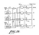
- light-emitting diodes 111, 112, 115 and 116 correspond to segments 11, 12, 15 and 16 respectively of the display output shown in Fig. 1B. Since tape present sensor 41 provides a logical one when a tape is present in transcribe station 5, and fast motion sensor 42 provides a logical one to point 45 when it detects that the tape is in a fast rewind mode, it will be apparent to those skilled in the art that the logic gates within block 90 will turn off light-emitting diodes 111, 112, 115 and 116 whenever a tape is not present in transcribe station 5; and that light-emitting diode 111 will be illuminated when the transcribe station is in an erase mode, LED 112 will be illuminated when the transcribe station is in a fast forward mode, LED 115 will be illuminated when tape is being reversed, and LED 116 will be illuminated when the transcribe station is in a listen or forward play mode.
Landscapes
- Engineering & Computer Science (AREA)
- Computer Hardware Design (AREA)
- Indexing, Searching, Synchronizing, And The Amount Of Synchronization Travel Of Record Carriers (AREA)
- Application Of Or Painting With Fluid Materials (AREA)
- Fittings On The Vehicle Exterior For Carrying Loads, And Devices For Holding Or Mounting Articles (AREA)
- Telephone Function (AREA)
Abstract
Description
- The present invention relates to a record member playback apparatus including a transport for moving the record medium of a record member alternately in a first direction and a second direction, advance position means for providing a rewind scan signal in response to said record medium being at the farthest position from an arbitrary starting point when said record medium has been moved in said first direction past a predetermined reference point, detection means for providing an E mark location signal upon each occurrence corresponding to detection of one of a plurality of E-signals recorded on said record medium; means for providing a motion signal in response to an increment of said record medium moving past said predetermined reference point in either first direction of said second direction; an improved display including a plurality of selectively actuable light sources for indication the location of said plurality of E signals.
- In dictation recording and transcribing equipment it is desirable to alert both the dictator and the transcriber to various states of machine operation and parameters of dictation segments.
- In dictation equipment using discrete record members, such as tape cassettes, it is desirable not only to provide information to the transcriber as to the mode in which a transcribe unit is operating, but also to provide a visual display denoting the end points of dictation segments and the location of certain instructions which have been recorded on the tape. It is known in the art to provide mechanical counters on dictation units which are coupled to a tape transport in order to indicate the amount of tape in a particular cassette which has been transcribed. Furthermore, it is known to provide a linear strip upon which visible indications of the ends of dictation segments and the location of instructions are printed either by ink, use of heat sensitive paper, or some other means.
- More recent developments of record member playback apparatus as mentioned above have provided a plurality of light-emitting segments which are maintained in a lit or unlit state as signals of a particular characteristic are located during a rewind operation. Such displays use a linear array of light emitting segments, each of which corresponds to a certain position on the tape in a discrete tape carrier, one example of such a display is shown in US-A 4 051 540. Conventionally the right-hand side (as the user faces the display) represents the end of the tape and the left-hand side represents the beginning. Regardless of which side of the array represents which end of the tape, these displays have entered the signal from the end of the display which represents the end of tape. When less than all of the tape in a discrete tape carrier has been used for dictation the physical end of the recording tape is reached prior to the end of the array. Therefore, this type of display requires that two steps be carried out by the operator in order to make the information in the display most useful. First the operator must completely rewind the tape in the discrete tape carrier in order to "fill" the display with the information available on the tape as to location of ends of dictation segments and locations of instructions. Secondly, when the physical beginning of the tape is reached the entire contents of the display must be justified (conventionally to the left) in order that the beginning of the physical tape corresponds to the portion of the array which represents the beginning of the tape. An example of. such a display is shown in US-A 4 200 893.
- At a dictate station in a dictation recording and transcribing system it has been known to provide a visible indication that a dictate station is operating in a recording mode. It has further been known to provide indicia on a strip of paper or the like which will indicate to the user the length of the dictation segment currently being dictated.
- It is the object of the present invention to avoid the disadvantages of the prior art and to create a record member playback apparatus as described above which makes it possible to alert the transcriber to various states of machine operation and parameters of dictation segments in a very effective and easy way.
- According the invention this object is realized by a sequential plurality of memory locations including first memory location, each of said plurality of memory locations including an E signal bit and a shutter bit, each of said plurality of light sources being connected (D1-D60) to and controlled by the contents of one of said plurality of memory locations, input means for entering said E-mark location signal as the contents of said E signal bit of said first memory location upon each occurrence of said E mark location signal during the concurrent presence of said rewind scan signal, shift logic associated with said plurality of memory locations for moving said E-mark location signals in each of said E-signal bits of said plurality of memory locations in a first memory direction to a next contiguous memory location upon each occurrence of said motion signal during the concurrent presence of said rewind scan signal; disabling logic for rendering said input means unresponsive to said detection means and for disabling said shaft logic during the absence of said rewind scan signal; shutter logic responsive to said transport, said advance position means, and said motion means for entering a shutter location signal into said shutter bit of said first memory location upon a first occurrence of said motion signal when said record medium is moving in said second direction; said shutter logic being responsive to shift said shutter location signal to said shutter bit of the next higher memory location in response to an occurrence of said motion signal during movement of said record medium in said second direction; said shutter logic being further responsive to shift said shutter location signal to said shutter bit of the next lower memory location in response to said motion signal during movement of said record medium in said first direction in the absence of said rewind scan signal from said advance position means, and further responsive to prevent shifting of said shutter location signal during the presence of said rewind scan signal during movement of said record medium in said first direction.
- According to a preferred embodiment of the invention each of said plurality of memory locations also including an I-signal bit; I-mark detection means for providing an I mark location signal in response to each occurrence of detection of one of a plurality of I-signals recorded on said record medium; I-signal input means for entering said I-mark location signal as the contents of said I-signal bit of said first memory locations upon each occurrence of said I-mark location signal during the concurrent presence of said rewind scan signal; and an I bit shift control connected to said shift logic for controlling shifting of said I mark location signals in said I signal bits of said plurality of memory locations.
- According to another aspect of the present invention the display has a surface including a right side and a left side; said plurality of light sources is disposed as a linear array from left to right on said surface of said record member playback apparatus; and said first memory direction corresponds to movement from left to right in said linear array.
- Therefore according the present invention an input arrangement is provided for entering an E mark location signal as the contents of the E signal bit of the first memory location upon each occurrence of detection of an E mark when a rewind scan operation as described further hereinbelow, has taken place. Shift logic is provided for moving the E mark location signals through the E signal bits of the memory locations each time a signal is received from the transport indicating that a predetermined increment of tape has been moved during the rewind scan operation. Disabling logic is also provided which disables the aforementioned input and the shift logic when the rewind scan terminates. Distinct shutter logic is provided for entering a binary shutter location signal into the shutter bit of the first memory location the first time that one of the motion signals is provided when the tape is wound in a forward direction. The shutter logic continues to shift the shutter location signal to the shutter bits of sequential memory locations in response to subsequent occurrences of the motion signal during forward movement of the tape.
- The shutter logic also will shift the shutter location signal in the opposite direction through the memory locations the tape is subsequent rewound but before the rewind scan operation commences. Shifting of the shutter location signal terminates when the rewind scan mode is reentered which occurs any time the type is rewound to the position closest to the beginning of the tape to which it has been rewound during any previous rewind scan operation.
- Other new and useful aspects of the present invention will apparent to those skilled in the art from the detailed description of the preferred embodiment which follows.
-
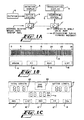
- Fig. 1A is a block diagram of an environment of the present invention.
- Fig. 1 B is a pictorial view of the preferred display output for a transcribe station in the preferred embodiment of the present invention.
- Fig. 1 C is a pictorial view of a display section for a dictation station.
- Fig. 2A is a schematic diagram of a preferred embodiment of the circuitry controlling the transcription display array of Fig. 1B.
- Fig. 2B is a schematic diagram of the circuitry controlling the transcription display function segments.
- Fig. 1A shows an environment of the present invention wherein a
dictator 6 records dictation at a dictate station 4 on atape cassette 7. Various parameters of the dictation being recorded are displayed ondictation display 8. , - A cassette .containing recorded dictation is shown as 7' and is supplied to transcribe
station 5 for transcription. The progress of a transcription operation taking place attranscribe station 5 is monitored ontranscription display 9. - Fig. 1B shows the display output for a transcription station of the preferred embodiment of the present invention. This display comprises an
array 10 of selectively actuable lighted segments which in the preferred embodiment disclosed comprises a linear array of sixty individual segments. The array of the preferred embodiment is selected to accommodate standard C-60 cassettes which will accept thirty minutes of recorded dictation per side. Each segment in the preferred embodiment represents approximately one-half minute of recording tape in a C-60 cassette. It is of course possible to use a greater or lesser number of segments in the array and the choice of sixty disclosed herein is an implementation of the preferred embodiment and should not be construed to limit the scope of the present invention. - The preferred embodiment of the transcription display also includes selectively
actuable segments - Each of the segments shown in Fig. 1 B, whether mode segments or segments of
linear array 10, may comprise any selectively actuable light source. As shown herein, each segment comprises a light-emitting diode (LED). The economics of manufacturing indicate that production of a large number of identical displays could be economically implemented by making each segment an individual segment of a single liquid crystal display. It will be understood that any actuable light source including light bulbs, may be used to construct an embodiment of the transcription display of the present invention. - Fig. 1C shows the display unit for a dictate station. The dictation display also includes
mode segments mode segment 18, indicates that the source of the input signal to the dictate station is a telephone interface. Such telephone interfaces are available as part of conventional PBX equipment and the interface per se forms no part of the present invention. -
End zone segment 22 is another selectively actuable light segment, the function of which will be described in greater detail below. -
Total length segment 20 shows a numerical readout indicating the total amount of tape upon which dictation has been recorded. In the preferred embodiment shown in Fig. 1C,total length segment 20 comprises a three digit numerical display, two for representing minutes, and the third digit representing tenths of minutes. Each numeral intotal length display 20 is formed by a conventional seven segment device and may be embodied by a seven segment LED displays, liquid crystal displays, nixie tubes, or the like. -
Letter length segment 21 indicates the length of the present dictation segment. Dictation segments in the environment of the present invention are defined as segments falling between "end marks" recorded on the tape. The operation ofletter length segment 21 and its response to certain function control commands will be described in greater detail below. - The dictation display also includes a conventional
real time clock 19 which per se forms no part of the present invention but is included for the convenience of the user. - The output of the transcription display shown in Fig. 1B as it relates to operation of a transcription station by a user will now be explained. This section of the disclosure will indicate the functioning of the output display as it relates to operations performed by a transcriber and the circuitry controlling the operation of this display will be described in the section immediately following the present section.
- In the transcription display of the present invention each segment of
linear array 10 represents a certain location on the tape in a cassette being transcribed. It is considered desirable in a transcription display to have a particular end of the display represent the farthest point to which the tape has been wound in a given direction. Conventionally, dictated cassettes provided to a transcriber are left in an unrewound configuration. In most western countries, the convention of reading from left to right is prevalent. Therefore, in the preferred embodiment, the left-hand end oflinear array 10 is chosen as representing the farthest point to which the cassette being transcribed has been rewound during all previous rewind operations. It is of course possible to use a configuration of lighted segments other than a linear array and to select another point on the array to represent the farthest point to which the tape has been rewound. However, it is considered preferable to use a linear array and furthermore considered preferable that the left-hand end of the array represent the farthest rewound position. - The environment of the present invention contemplates that the tape provided to the transcriptionist will contain both recorded dictation and recorded end marks (E marks) and instruction marks (I marks). The E marks recorded on the tape denote the end of a segment of dictation such as a letter or a memorandum. The I marks recorded on the tape are used to alert the transcriptionist to the location of instructions recorded on the tape by the dictator. A system for recording E marks and I marks of the type described above is disclosed in U.S. Patent 4,024,354 assigned to the same assignee as the present invention.
- Upon placing a cassette upon which dictation, E marks, and I marks have been recorded in a transcription unit, the transcriber will conventionally first begin to rewind the tape. The first mark to be encountered will be the last E mark on the tape denoting the end of the last dictation segment. This end mark will appear by lighting the farthest left-hand segment of
linear array 10 and maintaining it in a constantly lit state. As the rewinding of the tape proceeds, the farthest left-hand element oflinear array 10 will be extinguished and the next contiguous element oflinear array 10 to the right will become illuminated. Since the spacing between each element oflinear array 10 represents approximately thirty seconds of recording tape, each time thirty seconds of tape (approximately fifty-six inches for conventional cassettes) is rewound, the lighted segment representing the last end mark will be shifted to the right one segment. - If the last dictation segment recorded on the tape was five minutes long, the next to last end mark will appear at the farthest left-hand element of the
array 10 when the lighted segment representing the last end mark is at the tenth segment from the left-hand end ofarray 10, i.e., under thenumeral 5 which appears in Fig. 1 B. The illuminated segments representing end marks will continue to shift to the right so long as the tape is being rewound. Assume the next mark encountered on the tape being rewound is an instruction mark. Instruction marks appear at the left-hand end of the display as an intermittently lit segments ofarray 10 and thus the segment representing the location of an I mark will flash or blink in the display. As.the tape continues to be rewound, the flashing segment representing location of instruction mark will be shifted to the right in the same manner as the constantly lit segments representing end marks. - If at any time the rewinding procedure terminates, and the transcriptionist begins listening to the rewound portion of the tape, a second mode of display for
array 10 is initiated. As the .transcriptionist winds the tape forward, as will be done when listening to tape while transcribing it, the farthest left-hand segment of thearray 10 will continue to represent the segment of tape nearest the beginning of dictation that has been reached during rewind. This will be referred to as the farthest rewound position of the tape. As listening continues, each segment from the left-hand end ofarray 10 proceeding to the right will become continuously lit and remain continuously lit. It may therefore be seen that a "shutter" is provided which indicates to the transcriber how far from the farthest rewound position the tape has been advanced in a forward direction. - Thus, if the transcriber has listened to five minutes of dictation (or wound through five minutes of tape in a fast forward mode) from the farthest rewound position, the ten segments at the left-hand end of
array 10 will remain constantly lit indicating that the transcriber has advanced in a forward direction through five minutes of dictation from the farthest rewound position. It may therefore be seen that the shutter which appears onarray 10 comprises a plurality of continuously illuminated contiguous segments. As the shutter advances over a blinking segment indicating the presence of an I mark or a constantly lit segment indicating the presence of an E mark, the segment will remain continuously lit since it is then included in the shutter. - Continuing with the example, assume that the transcriber listened to five minutes of tape from the farthest rewound position thus illuminating the ten left-handmost segments of
array 10. Assume further that the transcriber then recommences rewinding of the tape. As the tape is rewound, the shutter will retreat back toward the left-hand end ofarray 10. Any segments which have been in the shutter that represent locations of E marks or I marks will continue to represent E marks or I marks as the shutter retreats and thus, E mark segments remain continuously lit and I mark segments will blink on and off once the shutter has retreated to the left past these locations. - Assume that the tape is rewound past the previous farthest rewind position and rewinding continues. When the farthest rewound position is reached, the shutter disappears since it will have retreated all the way to the left-hand end of
array 10. As rewinding continues, a new farthest rewound position is established, and all E marks and I marks located in the display will again proceed to be shifted to the right for each thirty seconds of tape rewound. As additional E marks or I marks are encountered on the tape during this rewind operation, such marks will be entered from the left-hand end ofarray 10 as described above. - Again, if at any point the transcriber proceeds to advance the tape in a forward direction, the left-hand end of
array 10 will represent the new farthest rewound position and the shutter will proceed to advance to the right as tape is advanced in a forward direction. - Therefore it may be seen that the farthest left-hand segment of
array 10 always represents the farthest rewound position and the presence or absence of the shutter will always indicate to the user whether he or she has advanced the tape in a forward direction from the farthest rewound position. - Furthermore, consider that only twenty minutes of dictation was recorded on the tape within the transcribe unit. If the tape is completely rewound, the farthest right-hand end mark (representing the end of dictation on the tape) will appear at the fortieth segment from the left under the numeral 20 when the tape is completely rewound. Therefore, upon complete rewinding of the tape, the display which appears in
array 10 will always be properly justified. - It will be further apparent that if the tape is only partially rewound before transcription begins, the display which appears in
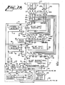
array 10 will also be properly justified since the left-hand end ofarray 10 will represent the point at which forward advance of the tape began. This feature represents a significance advance over prior lighted segment displays for transcribe units in that the display which appears in the array is constantly justified and requires no separate step of justification after a rewinding operation. It furthermore allows the display to always remain properly justified whether the tape being transcribed has been completely rewound or only partially rewound. - Figs. 2A and 2B show a preferred embodiment of the circuitry controlling the transcription display of the present invention. It will be appreciated by those skilled in the art from the description to follow of the circuitry of Figs. 2A and 2B that this circuitry will implement the functions of the transcription display described in the previous section.
- The circuitry of Fig. 2A controls
array 10 shown in Fig. 1B. The preferred embodiment disclosed herein is constructed using a plurality of sixty bit shift registers, 25, 26 and 27. As will be known to those skilled in the art, shift registers are memory devices which may be clocked to move the contents of a particular memory location to the next contiguous memory location in a given direction. It will be apparent to those skilled in the art that sixty bit shift registers may be constructed using large scale integration, or a combination of smaller medium scale integrated circuits. As used throughout this specification, the concept of contiguous memory locations comprises memory locations which are contiguous in address, without regard to the physical proximity, of the memory locations. It will therefore be apparent, that embodiments of the present invention may be constructed using random access memories which are controlled by a microprocessor and that in such an embodiment, contiguous memory locations comprise memory locations with contiguous addresses according to the addressing scheme of the microprocessor being used. Without regard to whether a sixty bit shift register is constructed as a unitary package, or a combination of smaller medium scale integrated circuit shift registers, registers 25, 26 and 27 have been shown as single devices for the sake of claritv. - As will become apparent from the description below,
shift register 25 contains signals representing the location of E marks,shift register 26 contains signals corresponding to the location of I marks andshift register 27 contains signals controlling the location of the shutter. Shift registers 25 and 26 are unidirectional and will be referred to as the E shift register and the I shift register, respectively, whileshift register 27 is bidirectional and will be referred to as the shutter shift register. - As is known to those skilled in the art, the contents of such shift registers may be set to zero either through the use of a direct clear input or through the parallel loading of zeros into all memory locations. Such an operation is desirable upon the ejection of a tape from the transcription unit. Implementation of this function will be apparent to those skilled in the art, and such implementation has been omitted from the circuitry of Fig. 2A for the sake of clarity.
- The outputs of
shift registers array 10 shown in Fig. 1A. - It will be understood that NOR gate drivers D1-D60 represent 60 NOR gate drivers and that drivers D4Ð68 have been omitted from Fig. 2A for clarity.
-
E mark detector 28 is responsive to the detection of E mark signals recorded on the tape in the transcribe unit. It will be understood thatE mark detector 28 responds to the presence of recorded E marks when the tape is running in a fast wind mode. Similarly, I markdetector 29 responds to the presence of I mark signals recorded on the tape in the transcription unit during fast winding. Such detectors may be implemented in a known manner by using two filters which respond to the frequencies of the respective signals over the range of possible fast wind speeds. Furthermore, such a detector for the fast wind mode is disclosed in U.S. Patent 3,882,545 assigned to the assignee of the present invention. - It will be understood that
E mark detector 28 provides a logical one output upon detection of an E mark recorded on the tape as the recorded E mark signal passes over the playback head of the transcription unit. Similarly I markdetector 29 will provide a logical one output upon detection of a signal corresponding to a recorded I mark. - The preferred embodiment of the present invention is also responsive to the presence of motion signals indicating that the tape is in motion.
Block 30 of Fig. 2A shows a means for providing motion signals. This means comprises amotion sensor 31 which provides output pulses alongline 32 when the tape is in motion. Such motion sensors are constructed by forming a mechanical linkage between either the supply or take-up spindles of the tape transport and providing a transducer such as a light chopper or a switch to provide pulses when the tape is in motion. An example of such a motion sensor is disclosed in U.S. Patent 3,820,101 assigned to the same assignee as the present invention. - The pulses which appear on
line 32 are scaled by counter 35 which provides a pulse output online 36 when a predetermined number of pulses have appeared online 32.Counter 35 is an up/ down counter that is responsive to the direction of tape travel as shown by the connection alongline 33 todirection sensor 39. It will be understood by those skilled in the art that counter 35 produces a pulse upon an overflow or an underflow condition. Since in the preferred embodiment, each segment ofarray 10 corresponds to approximately thirty seconds of recorded dictation and conventional cassette recording speed is used,counter 35 is selected so that it provides an output pulse online 36 in response to a number of pulses present online 32 which correspond to approximately fifty-six inches of tape (1-7/8 inches persecond times 30 seconds equals 56-1/4 inches). Of course other embodiments using a greater or lesser number of segments inarray 10 or different tape speeds are possible. In such other embodiments the proper scaling ofcounter 35 is within the ordinary level of skill in the art. A pulse appearing online 36 triggers one shot 37 which provides a motion signal pulse atpoint 38. - The present invention is also sensitive to the direction of tape movement. This is shown as
block 39 which indicates a conventional direction sensor which provides a logical zero online 40 when tape is moving in a forward direction and a logical one online 40 when tape is moving in a reverse direction. Shown in Fig. 2B is tapepresent sensor 41 which provides a logical one output when the presence of a cassette is detected in the transcribe station and afast motion sensor 42 which provides a logical one output to point 45 when pulses appearing online 32 appear at a sufficient rate to indicate that the transcribe station is moving the tape in a fast wind mode. Implementation ofelements - Erase
latch 46 is a conventional indication that the transcribe station is in an erase mode and provides a logical one on its Q output when the transcribe station is in an erase mode, and a logical zero on its Q output when the transcribe station is not in an erase mode. The NOT Q output of eraselatch 46 has a logical state that is opposite of that of the Q output. - To relate the circuitry shown in Fig. 2A to the display shown in Fig. 1A, it should be understood that LED L1 corresponds to the leftmost segment of
array 10. Similarly LED L2 corresponds to the second segment from the left-hand end ofarray 10 and LED L60 corresponds to the rightmost segment ofarray 10. From inspection of Fig. 2A, it will be apparent that NOR gate driver D1 controls LED L1, NOR gate driver D2 controls LED L2, and so forth until NOR gate driver D60 controls LED L60. It may further be seen that the inputs to NOR gate driver D1 comprise the Q1 outputs ofshift registers shift registers array 10 shown in Fig. 18. - Turning once again to Fig. 1A, it will be recalled that in the conventional environment of the present invention,
tape 7 is removed from dictate station 4 with recorded dictation wound onto the take-up reel. The first operation attranscribe station 5 is to rewind tape 7' in whole or in part. It is during this rewind operation in which the circuitry shown in Fig. 2A is first activated. Rewinding a portion of thetape 7 in order to generate a display indicating the location of E marks and I marks is referred to as a scan or scanning operation. During rewind, the tape, or a track of the tape devoted to E marks and I marks, is scanned for the presence of signals indicating an E mark or and I mark..As these are located, the circuitry of Fig. 2A generates a display which indicates the positions of E marks and I marks on the tape. - Note that shift registers 25 and 26 are each provided with a shift input, 47 and 48 respectively..---When a pulse is provided to such a shift input, the data stored in
memory location 1 is shifted tomemory location 2, the data inmemory location 2 is shifted tomemory location 3 and so forth. It will therefore be seen that when a pulse appears atshift input 47, the data in the memory locations ofshift register 25 all shift to the next contiguous memory location. In the convention set forth herein, this data may be considered as shifting to the right as the circuit is viewed in Fig. 2A. Similarly data is shifted to the right inshift register 26 when a pulse appears atshift input 48. - Shift registers 25 and 26 are also provided with DATA IN (DI)
inputs memory location 1 when a pulse appears onshift input 47. Similarly the data present at DATA INinput 50 will be shifted intomemory location 1 ofshift register 26 when a pulse appears onshift input 48. - The contents of each memory location of
shift registers memory location 1 ofshift register 25 appear on line E1 which is connected to the Q1 output ofshift register 25; the contents ofmemory location 2 ofshift register 25 appear on line E2 which is connected to the Q2 output ofshift register 25; and so forth through the contents ofmemory location 60 ofshift register 25 appearing on line E60. In a similar manner, the contents of memory locations 1-60 ofshift register 26 appear on lines 11-160. -
Shutter shift register 27 is a bidirectional shift register which means that data may be shifted in either direction within the register. This shift register is provided with adirection input 55 which determines the direction in which the data shifts in the register when a pulse appears on shift input 56. As shown in Fig. 2A, a zero present ondirection input 55 will cause data withinregister 27 to shift right when a pulse appears on SHIFT input 56 and a one ondirection input 55 will cause data to shift left when SHIFT input 56 is pulsed. Some off-the-shelf bidirectional shift registers have two direction inputs which must be in opposite logical states for the data to shift right or shift left, but implementation of a single line direction input such asdirection input 55 shown in Fig. 2A will be understood by one of ordinary skill in the art. -
Shutter shift register 27 is provided with twoserial data inputs 51 and 52. DATA INPUT RIGHT (DIR) 51 provides data which is shifted intomemory location 1 when a shift right condition occurs. A shift right condition is one in which a zero appears ondirection input 55 and a pulse appears on SHIFT input 56. Similarly, DATA INPUT LEFT (DIL) 52 provides data which is shifted intomemory location 60 when a shift left condition (direction input 55 equals 1, pulse on SHIFT input 56) occurs. As may be seen from Fig. 2A, DIR input 51 is tied to a logical one data state andDIL input 52 is tied to a logical zero state. It may therefore be appreciated that upon each occurrence of a shift right condition a logical one will be entered inmemory location 1 ofshift register 27 and that upon each occurrence of a shift left condition a logical zero will be entered intomemory location 60 ofshift register 27. -
Shift register 27 is also provided with a ZEROoutput 57 which goes to a logical one state when all sixty memory locations ofshutter shift register 27 contain a zero. Such an output may be available on an integrated device, or may be easily implemented by a plurality of NOR gates connected to lines S1-S60. As will be apparent from the description to follow, the embodiment of the present invention which is disclosed is constructed in such a manner that a logical zero at output Q1 ofshift register 27 necessarily implies that outputs Q2-Q60 are also zero. Therefore the state of ZEROoutput 57 may be treated simply as the local inverse of line S1 in the embodiment shown. In Fig. 2A, the ZERO output has been shown as asingle output 57 for the sake of simplicity. - Similarly, in an embodiment of the present invention using a microprocessor and sixty locations of random access memory to embody
shutter shift register 27, successive testing of all sixty addresses of random access memory corresponding to shuttershift register 27 may be implemented by the microprocessor in order to determine if ZEROoutput 57 should be in a logical one state. Since all memory locations ofshift register 27 to the left of the rightmost location containing a one will also contain ones (because DIR is tied to logical one), a microprocessor could be used to maintain a record of the rightmost location containing a one and treat all locations left of this as filled with ones. Thus it may be seen thatshift register 27 comprises a memory with a plurality of memory locations which is characterized by a numerical order to the memory locations. For location N, location N + 1 is the next higher memory location and location N - 1 is the next lower memory location. Shifting right as shown in Fig. 2A should be considered as shifting to the next higher memory location. - Consider, that a tape such as tape 7' as shown in Fig. 1A has been provided to the user of
transcribe station 5. As shown in Fig. 1A the first operation is to rewind a portion of tape 7' or to rewind it in its entirety. As noted above, the rewinding of a portion of tape 7' in order to generate a display denoting the location of E marks and I marks on the tape is called a rewind scan operation. This operation is implemented whenever a tape such as 7' is being rewound intranscribe station 5, and the tape has been wound past its previous farthest rewound position. - In the conventional environment of the present invention described above, it was noted that an E mark should be the first signal encountered upon rewinding of tape 7'. When the E mark is encountered upon rewind,
E mark detector 28 provides a pulse online 68.Line 68 is connected to the direct set (S) input of flip-flop 69 and therefore sets flip-flop 69 placing a logical one online 70 which is connected to the Q output of flip-flop 69. As may be seen from inspection of Fig. 2A, flip-flop 69 is a JK flip-flop which includes a direct SET (S) input, a grounded J input, a K input which is tied to a logical one, and a negative edge triggered clock (CLK) input which is connected toline 71. As will be known to those skilled in the art, when a positive pulse appears at the direct set input of a JK flip-flop such as flip-flop 69, the flip-flop is set to its Q equals one state without regard to the state of the other inputs. Therefore, whenE mark detector 28 detects the first E mark during a rewind scan operation, flip-flop 69 is set providing a one online 70 to the data in input ofshift register 25. - In the embodiment shown in Fig. 2A, ZERO
output 57 is the parameter by which the display control circuitry determines whether it is at its farthest rewound position. Consider for a moment that a freshly dictated tape is placed intranscribe station 5 and a rewind scan operation is begun. Under these conditions,motion sensor 31 will begin to provide pulses online 32 which will be counted by have been counted, a pulse appears online 36 which triggers one-shot 37 providing another pulse atpoint 38. - Note that under a rewind scan operation, the output of
direction sensor 39 which appears online 40 is a logical one. The logical one online 40 also appears online 58 as the input to direction input 55 ofshift register 27. Therefore,shift register 27 is conditioned to shift its contents in a left-hand direction upon receipt of a pulse at shift input 56. It is assumed herein that when the rewind scan operation begins, the contents ofshift register 27 have been cleared to all zeros in a manner described above. Therefore, a logical one appears at ZEROoutput 57 which is provided alongline 59 as an input toNAND gate 60.NAND gate 60 now has two ones as its inputs and a logical zero output ofNAND gate 60 appears atpoint 61. The logical zero atpoint 61 is inverted byinverter 62 and therefore a logical one appears online 65 as an input to ANDgate 67. - Consider for a moment, that the above-referenced E mark is the only mark located prior to provision of the first motion signal at
point 38 by oneshot 37. Recall that in the example given,point 61 is at a logical zero state. Sincepoint 61 is one input toNAND gate 72, the logical zero atpoint 61 will maintain a logical one state online 75 preventing the shifting of data inshift register 27. - The pulse that appears at
point 38 is also provided alongline 66 as an input to ANDgate 67. Sinceline 65 is in its logical one state, the appearance of a pulse online 66 causes a corresponding pulse to appear online 76, the output of ANDgate 67. The pulse which appears online 76 is provided alonglines inputs shift inputs inputs shift registers point 38, a zero is present at the data in input ofshift register 26 and is shifted into the first memory location of this register. Since a one is present online 70 as the input to Di input 49 ofshift register 25, a logical one is shifted into the first memory location ofshift register 25. - The pulse which appears on
line 76 is also provided as one input to ORgate 79. Through the action ofOR gate 79 the pulse appears atpoint 80 and is provided alonglines flops - As described above, flip-
flops flops lines flops flop 82 will remain in its Q equals zero state, and flip-flop 69 will be cleared from its Q equals one state to its Q equals zero state. It will further be appreciated that the clearing of flip-flop 69 occurs after the logical one formerly present online 70 has been shifted into the first memory location ofshift register 25. - As will be apparent from inspection of Fig. 2A, I mark
detector 29 and flip-flop 82 provide inputs to DATA IN input ofshift register 26 in a fashion which duplicates the operation ofE mark detector 28 and flip-flop 69 with respect to DATA INinput 49 ofshift register 25. If during the period between the appearance of the first motion pulse atpoint 38 and the second motion pulse an I mark is detected by I markdetector 29, then upon the appearance of the second motion pulse, a logical one will be shifted into the first memory location ofshift register 26. The falling edge of the pulse which appears online 81 will clear flip-flop 82 after the aforementioned logical one has been shifted into the first memory location. - Thus it may be seen that when an E mark is detected by
detector 28, flip-flop 69 will be set to enter a logical one into the first memory location ofshift register 25 upon the next occurrence of a tape motion signal atpoint 38. Similarly detection of an I mark by I markdetector 29 will assure that a logical one is shifted into the first memory location ofshift register 26 upon the next occurrence of a motion signal. - As will be known to those skilled in the art, if several motion pulses occur at
point 38, and bothE mark detector 28 and I markdetector 29·have failed to detect the presence of the respective signals, zeros will be shifted into the first memory locations ofshift registers - It may thus be seen that during a rewind scan operation, the circuitry of Fig. 2A will detect the presence of E marks and I marks recorded on the tape and will provide a logical one as the contents of the first memory location of
shift registers point 38. Upon each occurrence of a motion signal, the contents of each memory location ofshift registers - Consider for a moment that the circuitry of Fig. 2A is in a state in which a logical one is present in the second memory location of
shift register 25 and all other locations ofshift register 25 are equal to zero. Further assume that a logical one is present in the first memory location ofshift register 26 and all other memory locations ofshift register 26 are equal to zero. Assume also that during the period used in this example, no further E marks or I marks are detected. - The logical one present in the second memory location of
shift register 25 appears as a logical one on line E2 which is provided as one input to NOR gate driver D2. The logical one on line E2 causes the output of NOR gate driver D2 to go to its logical zero state and thus causes current to flow through light-emitting diode L2 causing this diode to light. Since light-emitting diode L2 corresponds to the second segment ofarray 10 shown in Fig. 1A, it may be seen that the second segment from the left-hand end ofarray 10 will remain constantly lit indicating the presence of an E mark. - The I mark located in the first memory location of
shift register 26 is provided along line 11 as an input to AND gate A1. The other input to AND gate A1 is provided byblink clock 85 which is an oscillator providing pulses at a predetermined frequency. Therefore pulses corresponding to the output ofblink clock 85 will appear on line 11' and therefore as an input to NOR gate driver D1. Since one input to NOR gate driver D1 is continuously pulsed, and the remaining two inputs to NOR gate driver D1 are zero, light-emitting diode L1 will intermittently conduct current and be cut off. It may therefore be seen that light-emitting diode L1 which corresponds to the left-handmost segment ofarray 10 in Fig. 1B will blink intermittently indicating the presence of an I mark. - Upon the next occurrence of the motion signal at
point 38, zeros will be present at DATA INinputs shift registers shift register 25 will be shifted to the third memory location ofshift register 25 while at the same time the logical one which was the contents of the first memory location ofshift register 26 will be shifted to the second memory location ofshift register 26. It will thus be apparent, that a logical one output will now be present on line E3 fromshift register 25 and through the action of NOR gate driver D3 will continuously light light-emitting diode L3 which corresponds to the third segment from the left ofarray 10. The logical one which is now present in the second memory location ofshift register 26 will cause pulses corresponding to the pulses emitted byblink clock 85 to appear on the line 12' and through the action of NOR gate driver D2 will intermittently light light-emitting diode L2. Therefore when the aforementioned motion signal appears atpoint 38, the continuously lighted segment representing location of an E mark and the intermittently lighted segment-representing the location of an I mark each shift one position to the right inarray 10 shown in Fig. 1 B. - It will be further appreciated that if an E mark and an I mark both occur in the same segment of tape between consecutive motion signals, that the E mark will "override" the I mark and the segment corresponding to that location will remain continuously lit due to the characteristics of the NOR gate drivers 01-060.
- Next assume that the rewind scan operation has stopped. This assumption should be made without regard to whether the tape has been completely rewound or only partially rewound. Assume that the operator of
transcribe station 5 now begins to move tape 7' in a forward direction in order to begin transcribing the recorded dictation contained on tape 7'. When the circuitry of Fig. 2A is in this state,direction sensor 39 is providing a logical zero online 40. Thus a logical zero is provided as one input toNAND gate 60 which maintains a logical one atpoint 61. This logical one is inverted byinverter 62 and maintains a logical zero online 65 as one input to ANDgate 67. The presence of a logical zero as one input to ANDgate 67 assures that a logical zero is maintained online 76 and thatline 76 remains insensitive to the presence of motion signals appearing atpoint 38. It may therefore be seen that when a logical zero is present online 40,line 76 will be maintained in its logical zero state and no pulses will appear at theshift inputs shift registers shift registers shift registers transcribe station 5 moves tape 7' in a forward direction. It will further be appreciated that the contents ofshift registers shift registers array 10 and thus the display apearing inarray 10 will be left justified to the farthest rewound position of the tape. - The logical zero on
line 40 also appears online 58 asdirection input 55 and thus will conditionshutter shift register 27 to shift right upon the occurrence of pulses at shift input 56. Recall thatpoint 61 is now at a logical one state. The logical one atpoint 61 is provided as an input toNAND gate 72.NAND gate 72 will then cause the state ofline 75 to be at the inverse of the logical state atpoint 38. Therefore,line 75 will remain in its logical one state until the occurrence of a motion signal atpoint 38. The occurrence of a positive going pulse as a motion signal atpoint 38 will cause a negative going pulse to appear online 75 that will be provided to shift input 56 ofshutter shift register 27. The rising edge of the pulse appearing online 75 will cause the memory contents ofshutter shift register 27 to shift to the next contiguous memory location to the right. Since the DATA IN RIGHT (DIR) input 51 is tied to a logical one state, a logical one will then become the contents of the first memory location ofshutter shift register 27. - Similarly upon the next occurrence of a motion signal at
point 38, the logical one that was previously the contents of the first memory location ofshift register 27 will become the contents of the second memory location, and another logical one from DATA IN RIGHT input 51 will be shifted into the first memory location. Recall that as long as a logical zero appears online 40, the contents ofshift registers point 38 the first three memory locations ofshutter shift register 27 will contain logical ones and light-emitting diodes L1-L3 will remain constantly lit. - It will therefore be apparent that as tape is moved in a forward direction, a band or shutter of continuously lighted segments will appear from the left-hand end of
array 10 and proceed toward the right-hand end ofarray 10. It will also be appreciated that the presence of a logical one in memory location N of shutter shift register 27 (N equal to a positive integer less than or equal to sixty) necessarily implies that the first N light-emitting diodes L1―LN will remain continuously lit without regard to the contents ofshift registers - Next assume, that from the state described immediately above, the operator of
transcribe station 5 again proceeds to rewind tape 7'. Under these conditions, the output online 40 will be a logical one and this logical one will be provided alongline 58 to direction input 55 conditioningshutter shift register 27 to shift in a left-hand direction. Since the contents of some memory locations of shutter-shift register 27 are equal to one, zerooutput 57 will be held to a logical zero state. This logical zero will be provided alongline 59 as the other input toNAND gate 60. Since a logical zero is provided alongline 59,NAND gate 60 assures thatpoint 61 remains in a logical one state without regard to the state ofline 40. The logical zero online 61 again maintains a logical zero online 65 through the action ofinverter 62 and therefore maintains a logical zero online 76 preventing shifting of the contents of memory location ofshift registers - As motion signals appears at
point 38, negative going pulses appear online 75 as the output ofNAND gate 72 and upon each rising edge of these pulses, the contents ofshutter shift register 27 shifts left. Each time the contents ofshift register 27 shifts left, a zero is entered inmemory location 60 ofshift register 27 since the DATA INPUT LEFT (DIL)input 52 is tied to a logical zero state. - This state of events persists until the tape reaches the point where the last motion pulse occurs at
point 38 prior to reaching the actual farthest rewound position. Upon completion of this pulse, the display control circuitry again assumes a state wherein it will execute a rewind scanning operation. When the last logical one shifts out of the first memory location ofshutter shift register 27, ZEROoutput 57 goes from a logical zero to a logical one state. - Assume that the operator of
transcribe station 5 continues to rewind after this point is reached. The transition from logical zero to logical one which appears at ZEROoutput 57 has two results. The first result is to reestablish the conditions described above wherein the circuitry will be responsive to perform a rewind. scanning operation. Note that a logical one now appears online 59 and a logical one also appears online 40. This provides two ones as inputs toNAND gate 60 which provides a zero atpoint 61 and a logical one online 65. As explained above, this state holdsline 75 at its logical one condition thus preventing shifting of the contents of memory locations ofshutter shift register 27 and enabling ANDgate 67 to pass pulses which appear online 66 ontoline 76 thereby activatingshift inputs shift registers - The second result of the transition from zero to one at ZERO
output 57 is that this transition appears online 86 and triggers a positive edge triggered oneshot multivibrator 87. Oneshot multivibrator 87 produces a short pulse online 88 which, through the action ofOR gate 79, appears atpoint 80 and thus onlines shift registers E mark detector 28 and I markdetector 29 would encounter recorded E marks and I marks and such encounters would set flip-flops flops shift register point 38. - As will be apparent to those skilled in the art, the circuitry of Fig. 2A will unambiguously and properly record all E marks and I marks unless the detection of an E mark or an I mark occurs simultaneously with a motion signal from
point 38. It is to be noted that the transition from zero to one at ZEROoutput 57 denotes that the particular segment of tape containing the farthest rewound position of the tape has been entered. In the preferred embodiment disclosed herein, the segments of tape between motion pulses represent approximately thirty seconds of dictated material. However, the provision of a greater number of memory locations in the shutter shift register, will increase the resolution and thus it could be determined with more accuracy when the farthest rewound position of the tape had been reached. From the foregoing it will be apparent to those skilled in the art that shuttershift register 27 not only provides contiguous memory locations for signals representing location of the shutter, but also provides an advance position means for determining when the tape has been wound to its previous farthest rewound position. - After the clearing of flip-
flops shot multivibrator 87, a rewind scan operation will continue as described hereinabove until the beginning of the tape (end of the rewind) has been reached. At this point, the farthest left-hand segment ofarray 10 shown in Fig. 1 B (which corresponds to LED L1 of array 10' shown in Fig. 2A) will represent the beginning of dictation on the tape 7' attranscribe station 5. - From the foregoing it should also be apparent that at any given point during operation of
transcribe station 5, light-emitting diode L1 will correspond to the segment of tape containing the farthest rewound position at that time. It will furthermore be apparent that any sequential combination of forward movement of the tape and reverse movement of the tape may be performed by the operator oftranscribe station 5 and the display of Fig. 1B will always be left justified, the leftmost end representing the farthest rewound position. When the tape is being moved within a segment of tape which has been advanced forward of the farthest rewound position,shutter shift register 27 will shift its memory contents left and right and the shutter will appear inarray 10 and correspondingly move left and right. When the farthest rewound position has been reached, the entire contents ofshutter shift register 60 will be equal to zero, ZEROoutput 57 will go to its logical one state, andshift registers - Turning to Fig. 2B, light-emitting
diodes segments present sensor 41 provides a logical one when a tape is present intranscribe station 5, andfast motion sensor 42 provides a logical one to point 45 when it detects that the tape is in a fast rewind mode, it will be apparent to those skilled in the art that the logic gates within block 90 will turn off light-emittingdiodes transcribe station 5; and that light-emitting diode 111 will be illuminated when the transcribe station is in an erase mode,LED 112 will be illuminated when the transcribe station is in a fast forward mode,LED 115 will be illuminated when tape is being reversed, andLED 116 will be illuminated when the transcribe station is in a listen or forward play mode. - The foregoing description of a preferred embodiment has been exemplary and for illustrative purposes. Other embodiments of the present invention are possible and considering the disclosure of the invention herein, such embodiments will be apparent to those of ordinary skill in the art. Therefore the scope of the present invention is to be limited only by the claims appended hereto.
Claims (4)
Priority Applications (1)
| Application Number | Priority Date | Filing Date | Title |
|---|---|---|---|
| AT80100282T ATE14356T1 (en) | 1979-04-09 | 1980-01-21 | PLAYER FOR A RECORDING CARRIER. |
Applications Claiming Priority (2)
| Application Number | Priority Date | Filing Date | Title |
|---|---|---|---|
| US06/027,990 US4352173A (en) | 1979-04-09 | 1979-04-09 | Dictation display device |
| US27990 | 1979-04-09 |
Publications (2)
| Publication Number | Publication Date |
|---|---|
| EP0017698A1 EP0017698A1 (en) | 1980-10-29 |
| EP0017698B1 true EP0017698B1 (en) | 1985-07-17 |
Family
ID=21840955
Family Applications (1)
| Application Number | Title | Priority Date | Filing Date |
|---|---|---|---|
| EP80100282A Expired EP0017698B1 (en) | 1979-04-09 | 1980-01-21 | Record member playback apparatus |
Country Status (6)
| Country | Link |
|---|---|
| US (1) | US4352173A (en) |
| EP (1) | EP0017698B1 (en) |
| JP (1) | JPS55174791U (en) |
| AT (1) | ATE14356T1 (en) |
| CA (1) | CA1154154A (en) |
| DE (1) | DE3070875D1 (en) |
Cited By (1)
| Publication number | Priority date | Publication date | Assignee | Title |
|---|---|---|---|---|
| DE3720433A1 (en) * | 1986-06-20 | 1987-12-23 | Olympus Optical Co | DISPLAY DEVICE FOR A RECORDING AND / OR PLAYBACK DEVICE |
Families Citing this family (9)
| Publication number | Priority date | Publication date | Assignee | Title |
|---|---|---|---|---|
| US4410923A (en) * | 1981-01-09 | 1983-10-18 | Dictaphone Corporation | Display apparatus for recording and/or playback device |
| US4398279A (en) * | 1981-05-04 | 1983-08-09 | Lanier Business Products, Inc. | Digital display for dictation transcriber for indicating remaining tape within discrete segments of dictation |
| US4686587A (en) * | 1983-12-21 | 1987-08-11 | Dictaphone Corporation | Record and/or playback device with cue signal indication and access |
| US4688117A (en) * | 1983-12-21 | 1987-08-18 | Dictaphone Corporation | Display including variable mode for a record and/or playback device |
| US4677501A (en) * | 1985-01-14 | 1987-06-30 | Dictaphone Corporation | Method and apparatus for displaying indications of instructions in previously recorded messages |
| US4924332A (en) * | 1986-08-08 | 1990-05-08 | Dictaphone Corporation | Display for modular dictation/transcription system |
| US4858213A (en) * | 1986-08-08 | 1989-08-15 | Dictaphone Corporation | Display for modular dictation/transcription system |
| US4809116A (en) * | 1986-08-08 | 1989-02-28 | Dictaphone Corporation | Modular dictation/transcription system having plural recording modules and a common display |
| US5956298A (en) * | 1997-11-10 | 1999-09-21 | Gough; Jesse Lynn | Voice prompting and indexing dictation recorder |
Family Cites Families (19)
| Publication number | Priority date | Publication date | Assignee | Title |
|---|---|---|---|---|
| AT251305B (en) * | 1965-03-12 | 1966-12-27 | Philips Nv | Recording and / or reproducing device |
| US3431367A (en) * | 1965-06-08 | 1969-03-04 | Canteen Corp | Playback apparatus for multiple magnetic tape cartridges |
| US3573360A (en) * | 1968-12-13 | 1971-04-06 | Ampex | Electronic web timer |
| JPS5136617B2 (en) * | 1972-07-25 | 1976-10-09 | ||
| US3882545A (en) * | 1972-11-15 | 1975-05-06 | Lanier Electronic Lab Inc | Apparatus and method for detecting tone signals occuring within a predetermined frequency range |
| US4051540A (en) * | 1976-04-20 | 1977-09-27 | Dictaphone Corporation | Instruction indicating apparatus for a record and/or playback device |
| BE855968A (en) * | 1976-07-05 | 1977-10-17 | Staar Sa | METHOD AND DEVICE FOR MONITORING AND COMMANDING THE TRANSFER OF MATERIAL FROM A DEBITRING COIL TO A RECEIVING COIL |
| AT354764B (en) * | 1976-08-13 | 1979-01-25 | Licentia Gmbh | MAGNETIC TAPE DEVICE |
| US4092680A (en) * | 1976-09-10 | 1978-05-30 | Dictaphone Corporation | Apparatus for indicating the farthest advance position of a bi-directionally movable medium |
| JPS53125505U (en) * | 1977-03-15 | 1978-10-05 | ||
| JPS5951054B2 (en) * | 1977-08-25 | 1984-12-12 | ソニー株式会社 | Recording/playback device |
| GB2003684B (en) * | 1977-08-30 | 1982-05-19 | Pioneer Electronic Corp | Electronic tuning type receiver with digital to analog converter |
| GB2003631B (en) * | 1977-08-30 | 1982-03-24 | Pioneer Electronic Corp | Magnetic tape running state and tape run amount display device |
| JPS5451510A (en) * | 1977-09-30 | 1979-04-23 | Olympus Optical Co Ltd | Tape recorder |
| JPS5451512A (en) * | 1977-09-30 | 1979-04-23 | Olympus Optical Co Ltd | Tape running direction display system of tape recorders |
| AT351810B (en) * | 1977-10-03 | 1979-08-10 | Stuzzi Radiotech | TAPE CASSETTE, IN PARTICULAR FOR DICTING DEVICES |
| DE2754368C2 (en) * | 1977-12-07 | 1981-10-08 | Licentia Patent-Verwaltungs-Gmbh, 6000 Frankfurt | Method and device for measuring and displaying the level of a tape-shaped winding material |
| DE2816732B1 (en) * | 1978-04-18 | 1979-07-12 | Assmann Gmbh | Device for displaying the location of special information, brands or instructions on a record carrier |
| US4200893A (en) * | 1978-05-17 | 1980-04-29 | Dictaphone Corporation | Instruction indicating apparatus for a record and/or playback device |
-
1979
- 1979-04-09 US US06/027,990 patent/US4352173A/en not_active Expired - Lifetime
-
1980
- 1980-01-21 DE DE8080100282T patent/DE3070875D1/en not_active Expired
- 1980-01-21 EP EP80100282A patent/EP0017698B1/en not_active Expired
- 1980-01-21 AT AT80100282T patent/ATE14356T1/en not_active IP Right Cessation
- 1980-04-09 JP JP1980047133U patent/JPS55174791U/ja active Pending
-
1983
- 1983-01-14 CA CA000419546A patent/CA1154154A/en not_active Expired
Cited By (1)
| Publication number | Priority date | Publication date | Assignee | Title |
|---|---|---|---|---|
| DE3720433A1 (en) * | 1986-06-20 | 1987-12-23 | Olympus Optical Co | DISPLAY DEVICE FOR A RECORDING AND / OR PLAYBACK DEVICE |
Also Published As
| Publication number | Publication date |
|---|---|
| JPS55174791U (en) | 1980-12-15 |
| EP0017698A1 (en) | 1980-10-29 |
| CA1154154A (en) | 1983-09-20 |
| DE3070875D1 (en) | 1985-08-22 |
| US4352173A (en) | 1982-09-28 |
| ATE14356T1 (en) | 1985-08-15 |
Similar Documents
| Publication | Publication Date | Title |
|---|---|---|
| US3792445A (en) | Vehicle data recording system | |
| US4399527A (en) | Dictation display device | |
| EP0017698B1 (en) | Record member playback apparatus | |
| EP0064674B1 (en) | Digital display for dictation transcriber | |
| US4007491A (en) | Dictation-transcription method and system | |
| US4200893A (en) | Instruction indicating apparatus for a record and/or playback device | |
| GB2170037A (en) | Method and apparatus for displaying indications of instructions in previously recorded messages | |
| US3812532A (en) | Random access memory with tape return to a midtape reference position after reading | |
| US4410923A (en) | Display apparatus for recording and/or playback device | |
| CA1082804A (en) | Instruction indication apparatus for a record and/or playback device | |
| KR870010511A (en) | Tape position detector | |
| US3895354A (en) | Program editor for machine control | |
| DE2816732B1 (en) | Device for displaying the location of special information, brands or instructions on a record carrier | |
| US4277674A (en) | Tape running direction indicator | |
| US3937927A (en) | Frame location system | |
| GB2157054A (en) | Tape recorders | |
| CA1185007A (en) | Dictation display device | |
| CA1319751C (en) | Display for modular dictation/transcription system | |
| US3614020A (en) | Tape rewind speed change system | |
| US3736580A (en) | Play back - machine control (position information storage and reproduction device) | |
| USRE32342E (en) | Instruction indicating apparatus for a record and/or playback device | |
| EP0053224B1 (en) | Magnetic recording apparatus | |
| SU858092A1 (en) | Device for record retrieval from magnetic carrier | |
| SU999100A1 (en) | Method and apparatus for marking and determining the end of magnetic tape | |
| JPS56124177A (en) | Tape counter device |
Legal Events
| Date | Code | Title | Description |
|---|---|---|---|
| PUAI | Public reference made under article 153(3) epc to a published international application that has entered the european phase |
Free format text: ORIGINAL CODE: 0009012 |
|
| AK | Designated contracting states |
Designated state(s): AT BE CH DE FR GB NL SE |
|
| TCAT | At: translation of patent claims filed | ||
| 17P | Request for examination filed |
Effective date: 19810309 |
|
| GRAA | (expected) grant |
Free format text: ORIGINAL CODE: 0009210 |
|
| AK | Designated contracting states |
Designated state(s): AT BE CH DE FR GB NL SE |
|
| PG25 | Lapsed in a contracting state [announced via postgrant information from national office to epo] |
Ref country code: FR Free format text: THE PATENT HAS BEEN ANNULLED BY A DECISION OF A NATIONAL AUTHORITY Effective date: 19850717 |
|
| REF | Corresponds to: |
Ref document number: 14356 Country of ref document: AT Date of ref document: 19850815 Kind code of ref document: T |
|
| REF | Corresponds to: |
Ref document number: 3070875 Country of ref document: DE Date of ref document: 19850822 |
|
| PGFP | Annual fee paid to national office [announced via postgrant information from national office to epo] |
Ref country code: NL Payment date: 19860131 Year of fee payment: 7 |
|
| PGFP | Annual fee paid to national office [announced via postgrant information from national office to epo] |
Ref country code: AT Payment date: 19860210 Year of fee payment: 7 |
|
| EN | Fr: translation not filed | ||
| PLBE | No opposition filed within time limit |
Free format text: ORIGINAL CODE: 0009261 |
|
| STAA | Information on the status of an ep patent application or granted ep patent |
Free format text: STATUS: NO OPPOSITION FILED WITHIN TIME LIMIT |
|
| 26N | No opposition filed | ||
| PG25 | Lapsed in a contracting state [announced via postgrant information from national office to epo] |
Ref country code: AT Effective date: 19870121 |
|
| PG25 | Lapsed in a contracting state [announced via postgrant information from national office to epo] |
Ref country code: SE Effective date: 19870122 |
|
| PG25 | Lapsed in a contracting state [announced via postgrant information from national office to epo] |
Ref country code: CH Effective date: 19870131 |
|
| BERE | Be: lapsed |
Owner name: LANIER BUSINESS PRODUCTS INC. Effective date: 19870131 |
|
| PG25 | Lapsed in a contracting state [announced via postgrant information from national office to epo] |
Ref country code: NL Effective date: 19870801 |
|
| GBPC | Gb: european patent ceased through non-payment of renewal fee | ||
| NLV4 | Nl: lapsed or anulled due to non-payment of the annual fee | ||
| REG | Reference to a national code |
Ref country code: CH Ref legal event code: PL |
|
| PG25 | Lapsed in a contracting state [announced via postgrant information from national office to epo] |
Ref country code: DE Effective date: 19871001 |
|
| PG25 | Lapsed in a contracting state [announced via postgrant information from national office to epo] |
Ref country code: GB Effective date: 19881118 |
|
| PG25 | Lapsed in a contracting state [announced via postgrant information from national office to epo] |
Ref country code: BE Effective date: 19890131 |
|
| EUG | Se: european patent has lapsed |
Ref document number: 80100282.5 Effective date: 19870923 |