EP0017676B1 - Method for determining a virtual longitudinal reactance in an electric net - Google Patents
Method for determining a virtual longitudinal reactance in an electric net Download PDFInfo
- Publication number
- EP0017676B1 EP0017676B1 EP79200189A EP79200189A EP0017676B1 EP 0017676 B1 EP0017676 B1 EP 0017676B1 EP 79200189 A EP79200189 A EP 79200189A EP 79200189 A EP79200189 A EP 79200189A EP 0017676 B1 EP0017676 B1 EP 0017676B1
- Authority
- EP
- European Patent Office
- Prior art keywords
- mains voltage
- phase angle
- values
- measuring point
- voltage phase
- Prior art date
- Legal status (The legal status is an assumption and is not a legal conclusion. Google has not performed a legal analysis and makes no representation as to the accuracy of the status listed.)
- Expired
Links
- 238000000034 method Methods 0.000 title claims description 27
- 238000001914 filtration Methods 0.000 claims 2
- 230000001629 suppression Effects 0.000 claims 1
- 238000005259 measurement Methods 0.000 description 8
- 230000006870 function Effects 0.000 description 5
- 238000010586 diagram Methods 0.000 description 3
- 230000001105 regulatory effect Effects 0.000 description 3
- 238000012360 testing method Methods 0.000 description 3
- 230000015572 biosynthetic process Effects 0.000 description 2
- 230000010354 integration Effects 0.000 description 2
- 230000005540 biological transmission Effects 0.000 description 1
- 230000000737 periodic effect Effects 0.000 description 1
- 238000012545 processing Methods 0.000 description 1
- 230000004044 response Effects 0.000 description 1
- 230000001360 synchronised effect Effects 0.000 description 1
- 238000012546 transfer Methods 0.000 description 1
Images


Classifications
-
- G—PHYSICS
- G01—MEASURING; TESTING
- G01R—MEASURING ELECTRIC VARIABLES; MEASURING MAGNETIC VARIABLES
- G01R27/00—Arrangements for measuring resistance, reactance, impedance, or electric characteristics derived therefrom
- G01R27/02—Measuring real or complex resistance, reactance, impedance, or other two-pole characteristics derived therefrom, e.g. time constant
- G01R27/16—Measuring impedance of element or network through which a current is passing from another source, e.g. cable, power line
-
- G—PHYSICS
- G01—MEASURING; TESTING
- G01R—MEASURING ELECTRIC VARIABLES; MEASURING MAGNETIC VARIABLES
- G01R27/00—Arrangements for measuring resistance, reactance, impedance, or electric characteristics derived therefrom
- G01R27/02—Measuring real or complex resistance, reactance, impedance, or other two-pole characteristics derived therefrom, e.g. time constant
Definitions
- the invention relates to a method for determining a longitudinal equivalent reactance in an electrical network between a measurement location and a location of amplitude and phase-locked mains voltage, in particular at the connection location of a generator to a line network.
- Certain reactance values of the network are required as parameter quantities or signals when managing and regulating electrical high-performance networks, in particular also when regulating the generators contained in the network.
- It is essentially the internal reactance of a substitute source representing the mentioned network section with the rigid network voltage mentioned as an impressed source voltage. Since it is a longitudinal reactance, the resistances and capacitances compared to the inductances can generally be neglected, which justifies the sole treatment of a substitute reactance.
- the value of the longitudinal equivalent reactance of a network with regard to a measurement location can in principle be determined from the entire network configuration, taking into account the respective load conditions. However, such a determination is not applicable for practical operation because the load state and the network configuration are subject to more or less strong, ongoing changes, which is why a comprehensive measurement and data transmission system would be required to record it.
- the object of the invention is therefore to create a method for determining the longitudinal substitute reactance with respect to a measuring location from only with the aid of the measurement variables available here, the effort generally being to be kept in such a framework that repeated or ongoing reactance determination for the purposes of network management and Generator control is possible.
- the solution to this problem according to the invention is characterized by the features specified in claim 1.
- the basic idea of the method according to the invention is to determine and to determine the associated values of the mains voltage phase angle difference on both sides of this reactance for a plurality of predetermined values of the desired longitudinal equivalent reactance using measured variables obtained exclusively at the measurement location, namely mains voltage, active and reactive power to compare a phase angle of the local mains voltage, which is determined directly from the aforementioned measurement variables, with respect to a local reference.
- the relatively best agreement between one of the phase angle differences calculated with an equivalent reactance value and the local mains voltage phase angle is then used as a criterion for the selection of the associated, specified reactance value as an approximation result.
- the mentioned phase angle difference on both sides of the longitudinal reactance is namely nothing other than the phase angle of the local mains voltage compared to the rigid equivalent source voltage.
- the local mains voltage V 1 as well as the active power P and the reactive power Q are recorded in corresponding measuring devices Gp and G o at a measuring location x m , for example the connection location of a generator G.
- the network section coupled to the measurement site or the generator is represented by a replacement source with the longitudinal or internal response X E and with the rigid source voltage V 2 .
- the active power P is absorbed or given off by this rigid source.
- the local mains voltage V 1 is fed together with an at least approximately rigid reference voltage V r from a local oscillator Os to a phase angle measuring device PM, and the local mains voltage phase angle d m is thus formed in the form of a measured variable.
- the signals or measured variables d 1 to d 3 and d m are conducted via filters F, which are linear in time Suppress components of the signals in question, ie constant and ramp components, which are of no interest for the usual dynamic control and regulation and would make the subsequent similarity check more difficult.
- filters F are linear in time Suppress components of the signals in question, ie constant and ramp components, which are of no interest for the usual dynamic control and regulation and would make the subsequent similarity check more difficult.
- Suitable filter circuits with differential and integral components of their transfer function, which are customary per se, can in principle be used here.
- a phase angle difference d 1 to d 3 is then subjected to a similarity test in a correlation circuit G k with respect to the course of the local phase angle d m .
- These are generally correlation circuits, for example integrating cross-correlators, each of which supplies a correlate K 1 to K 3 as a similarity parameter.
- a synchronous pulse generator SY is provided which, after a time interval T, sends a synchronization or reset signal sy to the correlators.
- This signal also ensures a periodic synchronization of the oscillator Us with the local mains voltage in order to correct any drift phenomena.
- this signal causes the correlates K 1 to K 3 to be output to a limit value selection circuit GG shortly before the correlator integrators are reset.
- a limit value selection circuit GG In the case of a simple cross-correlation, the correlate representing a similar measure of the similarity of the course sections, a maximum value selection circuit is to be used here, with inverse assignment, which is also basically applicable, a minimum value selection circuit is to be used.
- the limit value selection circuit GG has the outputs 1, K 3 assigned to the correlates K 1 to K 3 , in each case only that output carrying an affirmative binary signal which is assigned to the largest correlate or phase angle difference d 1 to d 3 which is shown in FIG their course is most similar to that of the local phase angle d m .
- the associated, predetermined equivalent reactance value X e1 to X e3 is then switched through to the output A via an output logic AL.
- FIG. 2 shows, over time t, three, for example, given courses of the phase angle differences d 1 to d 3 for correspondingly different, predetermined values of the equivalent reactance X e1 to X e3 .
- these values are selected based on plausibility considerations, taking into account the known rough network conditions, so that the actual reactance value lies in the range of variation of the specified values.
- the similarity test of the course, in each case over a time interval T can, for example, as illustrated in FIG. 2, by forming a difference between d m and d 1 to d 3 (see the hatched difference areas) with correlating the difference value with one of the difference-forming variables, for example d m , be performed. In this case there is an inverse similarity criterion with a corresponding minimum value selection.
- the correlation itself can be carried out in the usual way by multiplication - in the example, the difference value - with one of the difference-forming quantities and integration over the interval T.
- each a set of metrics d m, P, Q, V 1 is housed in process step a) following the procedure start and subsequently in process step b) the size d m in a memory Sp outputted.
- the variable d 1 of the phase angle difference is determined in method step c) and output in the memory Sp in the subsequent step d).
- the method continues in this way with the introduction of the other specified reactance values up to X e3 with formation and output of the last value of the phase angle difference, for example d 3 .
- a new cycle cycle follows, starting with the recording of a new set of the measured variables d m , P, Q, V 1 .
- a memory which is cyclically renewed step by step a so-called “rotating” memory, in which the courses of the variables d m and d 1 to d 3 are stored over a time interval T.
- the renewal is carried out in the usual way by overwriting the longest stored value set by the last recorded one. Suitable history sections are therefore always available in the memory for the similarity check.
- the process can then continue cyclically, so that there is constant network identification for regulatory and management purposes.
Landscapes
- Physics & Mathematics (AREA)
- General Physics & Mathematics (AREA)
- Measurement Of Resistance Or Impedance (AREA)
Description
Die Erfindung bezieht sich auf ein Verfahren zur Bestimmung einer Längs-Ersatzreaktanz in einem elektrischen Netz zwischen einem Meßort und einem Ort amplituden- und phasenstarrer Netzspannung, Insbesondere am Anschlussort eines Generators an ein Leitungsnetz.The invention relates to a method for determining a longitudinal equivalent reactance in an electrical network between a measurement location and a location of amplitude and phase-locked mains voltage, in particular at the connection location of a generator to a line network.
Bei der Führung und Regelung von elektrischen Hochleistungsnetzen, insbesondere auch bei der Regelung der im Netz enthaltenen Generatoren, werden gewisse Reaktanzwerte des Netzes als Parametergrössen oder -signale benötigt. Hierzu gehört die Längs-Ersatzreaktanz bezüglich eines Messortes, d.h. die Längsreaktanz zwischen der Netzspannung am Messort einerseits und einer als amplituden- und phasenstarr anzunehmenden Netzspannung, welche also den mit dem betreffenden Messort bzw. mit dem hier angeechlossenen Generator gekoppelten Netzabschnitt begrenzt. Es handelt sich dabei im wesentlichen um die Innenreaktanz einer den genannten Netzabschnitt repräsentierenden Ersatzquelle mit der erwähnten, starren Netzspannung als eingeprägter Quellenspannung. Da es sich um eine Längsreaktanz handelt, können die Resistanzen und Kapazitanzen gegenüber den Induktanzen im allgemeinen vernachlässigt werden, was zu der alleinigen Behandlung einer Ersatzreaktanz berechtigt.Certain reactance values of the network are required as parameter quantities or signals when managing and regulating electrical high-performance networks, in particular also when regulating the generators contained in the network. This includes the longitudinal equivalent reactance with regard to a measurement location, i.e. the longitudinal reactance between the mains voltage at the measuring location on the one hand and a mains voltage to be assumed to be amplitude and phase-locked, which thus limits the network section coupled to the relevant measuring location or to the generator connected here. It is essentially the internal reactance of a substitute source representing the mentioned network section with the rigid network voltage mentioned as an impressed source voltage. Since it is a longitudinal reactance, the resistances and capacitances compared to the inductances can generally be neglected, which justifies the sole treatment of a substitute reactance.
Der Wert der Längs-Ersatzreaktanz eines Netzes bezüglich eines Messortes kann grundsätzlich aus der gesamten Netzkonfiguration unter Berücksichtigung der jeweiligen Lastzustände ermittelt werden. Für den praktischen Betrieb ist eine solche Ermittlung jedoch nicht anwendbar, weil der Lastzustand und auch die Netzkonfiguration mehr oder weniger starken, laufenden Aenderungen unterliegen, weshalb eine Erfassung ein umfangreiches Mess- und Daten- übermittlungssystem zur Voraussetzung hätte. Aufgabe der Erfindung ist daher die Schaffung eines Verfahrens zur Bestimmung der Längs-Ersatzreaktanz bezüglich eines Messortes aus schliesslich unter Zuhilfenahme von hier verfügbaren Messgrössen, wobei der Aufwand grundsätzlich in einem solchen Rahmen zu halten ist, dass eine wiederholte oder laufende Reaktanzbestimmung für Zwecke der Netzführung und Generatorregelung möglich ist. Die erfindungsgemisse Lösung dieser Aufgabe kennzeichnet sich durch die im Anspruch 1 angegebenen Merkmale.The value of the longitudinal equivalent reactance of a network with regard to a measurement location can in principle be determined from the entire network configuration, taking into account the respective load conditions. However, such a determination is not applicable for practical operation because the load state and the network configuration are subject to more or less strong, ongoing changes, which is why a comprehensive measurement and data transmission system would be required to record it. The object of the invention is therefore to create a method for determining the longitudinal substitute reactance with respect to a measuring location from only with the aid of the measurement variables available here, the effort generally being to be kept in such a framework that repeated or ongoing reactance determination for the purposes of network management and Generator control is possible. The solution to this problem according to the invention is characterized by the features specified in
Der Grundgedanke des erfindungsgemässen Verfahrens besteht darin, für eine Mehrzahl von vorgegebenen Werten der gesuchten Längs-Ersatzreaktanz unter Verwendung von ausschliesslich am Messort gewonnenen Messgrössen, nämlich Netzspannung, Wirk- und Blindleistung, die zugehörigen Werte der Netzspannungs-Phasenwinkeidifferenz beiderseits dieser Reaktanz zu bestimmen und mit einem unmittelbar aus den genannten Messgrössen bestimmten Phasenwinkel der lokalen Netzspannung gegenüber einer lokalen Referenz zu vergleichen. Die relativ beste Uebereinstimmung zwischen einem der mit einem Ersatzreaktanzwert berechneten Phasenwinkeldifferenz und dem lokalen Netzspannungs-Phasenwinkel wird sodann als Kriterium für die Auswahl des zugehörigen, vorgegebenen Reaktanzwertes als Näherungsergebnis verwendet. Die genannte Phasenwinkeldifferenz beiderseitz der Längsreaktanz ist nämlich nichts anderes als der Phasenwinkel der lokalen Netzspannung gegenüber der starren Ersatzquellenspannung.The basic idea of the method according to the invention is to determine and to determine the associated values of the mains voltage phase angle difference on both sides of this reactance for a plurality of predetermined values of the desired longitudinal equivalent reactance using measured variables obtained exclusively at the measurement location, namely mains voltage, active and reactive power to compare a phase angle of the local mains voltage, which is determined directly from the aforementioned measurement variables, with respect to a local reference. The relatively best agreement between one of the phase angle differences calculated with an equivalent reactance value and the local mains voltage phase angle is then used as a criterion for the selection of the associated, specified reactance value as an approximation result. The mentioned phase angle difference on both sides of the longitudinal reactance is namely nothing other than the phase angle of the local mains voltage compared to the rigid equivalent source voltage.
Die Erfindung wird weiter anhand der in den Zeichnungen veranschaulichten Ausführungsbeispiele erläutert. Hierin zeigt :
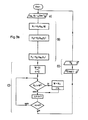
Figur 1 das Blockbild einer Schaltungsanordnung zur Ersatzreaktanzbestimmung nach dem erfindungsgemässen Verfahren,Figur 2 ein Phasenwinkel-Zeitdiagramm zur Erläuterung der Verfahrensweise und- Figuren 3a und 3b Zeitablaufdiagramme zur Durchführung des erfindungsgemässen Verfahrens in allgemeiner Form.
- FIG. 1 shows the block diagram of a circuit arrangement for determining the reactance by the method according to the invention,
- Figure 2 is a phase angle time diagram to explain the procedure and
- Figures 3a and 3b timing diagrams for performing the inventive method in general form.
Nach Fig. 1 werden an einem Messort xm, beispielsweise dem Anschlussort eines Generators G, die lokale Netzspannung V1 sowie die Wirkleistung P und die Blindleistung Q in entsprechenden Messeinrichtungen Gp und Go erfasst. Der mit dem Messort bzw. dem Generator gekoppelte Netzabschnitt ist gemäss vorstehenden Erläuterungen durch eine Ersatzquelle mit der Längs- oder lnnenreaktaz XE und mit der starren Quellenspannung V2 repräsentiert. Die Wirkleistung P wird durch diese starre Quelle aufgenommen oder abgegeben.According to FIG. 1, the local mains voltage V 1 as well as the active power P and the reactive power Q are recorded in corresponding measuring devices Gp and G o at a measuring location x m , for example the connection location of a generator G. According to the above explanations, the network section coupled to the measurement site or the generator is represented by a replacement source with the longitudinal or internal response X E and with the rigid source voltage V 2 . The active power P is absorbed or given off by this rigid source.
Aus P und Q sowie dem in einem Funktionsgeber Gq gebildeten Quadrat V12 der lokalen Netzspannung werden sodann in einer Mehrzahl von Funktionsgebern Gd mit je einem von aussen zugeführten, vorgegebenen Ersatzreaktanzwert Xe1 bis Xe3 entsprechende Zeitverläufe einer Netzspannungs-Phasenwinkeldifferenz d1 bis d3 gebildet. Diese Funktionsgeber arbeiten nach der an sich allgemein bekannten Beziehung
Für die Verwirklichung einer solchen Funktion können allgemein übliche und daher hier nicht näher zu erläuternde Analogoder Digitalschaltungen verwendet werden, die grundsätzlich kommerziell erhältlich sind.For the implementation of such a function, generally customary and therefore not to be explained here analog or digital circuits can be used, which are basically commercially available.
Ferner wird die lokale Netzspannung V1 zusammen mit einer wenigstens annähernd starren Referenzspannung Vr aus einem lokalen Oszillator Os einem Phasenwinkel-Messgerät PM zugeführt und damit der lokale Netzspannungs-Phasenwinkel dm in Form einer Messgrösse gebildet. Die Signale bzw. Messgrössen d1 bis d3 und dm sind über Filter F geführt, die zeitlich lineare Komponenten der betreffenden Signale unterdrücken, d.h. Gleich- und Rampenkomponenten, die für die übliche dynamische Führung und Regelung uninteressant sind und die nachfolgende Aehnlichkeitsprüfung erschweren würden. Geeignete, an sich übliche Filterschaltungen mit Differential- und Integralkomponente ihrer Uebertragungsfunktion können hier grundsätzlich verwendet werden.Furthermore, the local mains voltage V 1 is fed together with an at least approximately rigid reference voltage V r from a local oscillator Os to a phase angle measuring device PM, and the local mains voltage phase angle d m is thus formed in the form of a measured variable. The signals or measured variables d 1 to d 3 and d m are conducted via filters F, which are linear in time Suppress components of the signals in question, ie constant and ramp components, which are of no interest for the usual dynamic control and regulation and would make the subsequent similarity check more difficult. Suitable filter circuits with differential and integral components of their transfer function, which are customary per se, can in principle be used here.
Anschliessend wird der Verlauf je einer Phasenwinkeldifferenz d1 bis d3 in Bezug auf den Verlauf des lokalen Phasenwinkels dm in einer Korrelationsschaltung Gk einer Aehnlichkeitsprüfung unterzogen. Es handelt sich hierbei um grundsätzlich übliche Korrelationsschaltungen, beispielsweise um integrierende Kreuzkorrelatoren, die je ein Korrelat K1 bis K3 als Aehnlichkeits-Kenngrösse liefern. Im Beispielsfall ist angenommen, dass die Integration dieser Korrelatoren und damit die Aehnlichkeitsprüfung über definierte Zeitintervalle entsprechend jeweils einem bestimmten Verlaufsabschnitt der zugeführten Signale erfolgt. Dazu ist ein Synchron-Impulsgeber SY vorgesehen, der jeweils nach einem Zeitintervall T ein Synchronisier- bzw. Rückstellsignal sy an die Korrelatoren gibt. Dieses Signal sorgt auch für eine periodische Synchronisierung des Oszillators Us mit der lokalen Netzspannung zur Korrektur etwaiger Drifterscheinungen. Ausserdem bewirkt dieses Signal jeweils kurz vor der Rückstellung der Korrelator-Integratoren die Ausgabe der Korrelate K1 bis K3 an eine Grenzwert-Auswahlschaltung GG. Im Falle einer einfachen Kreuzkorrelation, wobei das Korrelat ein gleichsinniges Mass für die Aehnlichkeit der Verlaufsabschnitte darstellt, ist hier eine Maximalwert-Auswahlschaltung, bei inverser Zuordnung, die ebenfalls grundsätzlich anwendbar ist, eine Minimalwert-Auswahlschaltung zu verwenden. Die Grenzwert-Auswahlschaltung GG weist den Korrelaten K1 bis K3 zugeordnete, nicht näher bezeichnete Ausgänge auf, wobei jeweils nur derjenige Ausgang ein bejahendes Binärsignal führt, welcher dem jeweils grössten Korrelat bzw. derjenigen Phasenwinkeldifferenz d1 bis d3 zugeordnet ist, welche in ihrem Verlauf die grösste Aehnlichkeit mit demjenigen des lokalen Phasenwinkels dm aufweist. Der zugehörige, vorgegebene Ersatzreaktanzwert Xe1 bis Xe3 wird dann über eine Ausgabelogik AL als Ergebnis zum Ausgang A durchgeschaltet.The course of a phase angle difference d 1 to d 3 is then subjected to a similarity test in a correlation circuit G k with respect to the course of the local phase angle d m . These are generally correlation circuits, for example integrating cross-correlators, each of which supplies a correlate K 1 to K 3 as a similarity parameter. In the example, it is assumed that the integration of these correlators and thus the similarity check takes place over defined time intervals in each case in accordance with a specific course section of the supplied signals. For this purpose, a synchronous pulse generator SY is provided which, after a time interval T, sends a synchronization or reset signal sy to the correlators. This signal also ensures a periodic synchronization of the oscillator Us with the local mains voltage in order to correct any drift phenomena. In addition, this signal causes the correlates K 1 to K 3 to be output to a limit value selection circuit GG shortly before the correlator integrators are reset. In the case of a simple cross-correlation, the correlate representing a similar measure of the similarity of the course sections, a maximum value selection circuit is to be used here, with inverse assignment, which is also basically applicable, a minimum value selection circuit is to be used. The limit value selection circuit GG has the outputs 1, K 3 assigned to the correlates K 1 to K 3 , in each case only that output carrying an affirmative binary signal which is assigned to the largest correlate or phase angle difference d 1 to d 3 which is shown in FIG their course is most similar to that of the local phase angle d m . The associated, predetermined equivalent reactance value X e1 to X e3 is then switched through to the output A via an output logic AL.
Fig. 2 zeigt über der Zeit t drei beispielsweise angegebene Verläufe der Phasenwinkeldifferenzen d1 bis d3 für entsprechend unterschiedliche, vorgegebene Werte der Ersatzreaktanz Xe1 bis Xe3. Diese Werte werden in der Praxis nach Plausibilitätserwägungen unter Berücksichtigung der bekannten Grob- Netzverhältnisse so gewählt, dass der wirkliche Reaktanzwert im Variationsbereich der vorgegebenen Werte liegt. Die Aehnlichkeitsprüfung des Verlaufs, jeweils über ein Zeitintervall T, kann beispielsweise wie in Fig. 2 veranschaulicht durch Differenzbildung zwischen dm und d1 bis d3 (siehe die schraffierten Differenzflächen) mit Korrelation des Differenzwertes mit einer der differenzbildenden Grössen, beispielsweise dm, durchgeführt werden. In diesem Fall ergibt sich ein inverses Aehnlichkeitskriterium mit entsprechender Minimalwertauswahl. Die Korrelation selbst kann in üblicher Weise durch Multiplikation - im Beispielsfall also des Differenzwertes - mit einer der differenzbildenden Grössen und Integration über das Intervall T durchgeführt werden.FIG. 2 shows, over time t, three, for example, given courses of the phase angle differences d 1 to d 3 for correspondingly different, predetermined values of the equivalent reactance X e1 to X e3 . In practice, these values are selected based on plausibility considerations, taking into account the known rough network conditions, so that the actual reactance value lies in the range of variation of the specified values. The similarity test of the course, in each case over a time interval T, can, for example, as illustrated in FIG. 2, by forming a difference between d m and d 1 to d 3 (see the hatched difference areas) with correlating the difference value with one of the difference-forming variables, for example d m , be performed. In this case there is an inverse similarity criterion with a corresponding minimum value selection. The correlation itself can be carried out in the usual way by multiplication - in the example, the difference value - with one of the difference-forming quantities and integration over the interval T.
Fig. 3a zeigt einen ersten, zyklisch ablaufenden Abschnitt des Verfahrens. Danach wird im Anschluss an den Verfahrensstart jeweils ein Satz von Messgrössen dm, P, Q, V1 im Verfahrensschritt a) aufgenommen und anschliessend im Verfahrensschritt b) die Grösse dm in einen Speicher Sp ausgegeben. Anschliessend wird unter Verwendung der Messgrössen P, Q, V1 und des vorgegebenen Reaktanzwertes Xe1 die Grösse d1 der Phasenwinkeldifferenz im Verfahrensschritt c) bestimmt sowie im anschliessenden Schritt d) in den Speicher Sp ausgegeben. Das Verfahren läuft in dieser Weise weiter mit Einführung der übrigen vorgegebenen Reaktanzwerte bis Xe3 mit Bildung und Ausgabe des letzten Wertes der Phasenwinkeldifferenz, beispielsweise also d3. Es folgt ein neuer Zyklusdurchlauf, beginnend mit Aufnahme eines neuen Satzes der Messgrössen dm, P, Q, V1.3a shows a first, cyclically running section of the method. Thereafter, each a set of metrics d m, P, Q, V 1 is housed in process step a) following the procedure start and subsequently in process step b) the size d m in a memory Sp outputted. Then, using the measured variables P, Q, V 1 and the predetermined reactance value X e1, the variable d 1 of the phase angle difference is determined in method step c) and output in the memory Sp in the subsequent step d). The method continues in this way with the introduction of the other specified reactance values up to X e3 with formation and output of the last value of the phase angle difference, for example d 3 . A new cycle cycle follows, starting with the recording of a new set of the measured variables d m , P, Q, V 1 .
Zweckmässig wird ein seinen Inhalt zyklisch schrittweise erneuerter Speicher, ein sogenannter « rotierender » Speicher, verwendet, in dem jeweils die Verläufe der Grössen dm und d1 bis d3 über ein Zeitintervall T gespeichert ist. Die Erneuerung erfolgt in üblicher Weise durch Ueberschreiben des jeweils am längsten gespeicherten Wertesatzes durch den zuletzt aufgenommenen. Im Speicher stehen also immer geeignete Verlaufsabschnitte für die Aehnlichkeitsprüfung zur Verfügung.It is expedient to use a memory which is cyclically renewed step by step, a so-called “rotating” memory, in which the courses of the variables d m and d 1 to d 3 are stored over a time interval T. The renewal is carried out in the usual way by overwriting the longest stored value set by the last recorded one. Suitable history sections are therefore always available in the memory for the similarity check.
Die weitere Verarbeitung, wiederum im zyklischen Ablauf, ist in Fig. 3b veranschaulicht. Hier wird nach dem Start im Verfahrensschritt a) jeweils ein sich über das lntervall T erstreckender Wertesatz der Grössen dm, d1 bis d3 aufgenommen und anschliessend im mehrschrittigen Verfahrensabschnitt B) der Aehnlichkeitsprüfung mit Bildung der Korrelate K1 bis - allgemein - Kk unterzogen. Sodann erfolgt im Verfahrensabschnitt C) unter Zuhilfenahme einer Anfangs gleich K1 gesetzten Hilfsgrösse W sowie der Laufnummern i und n die Grenzwertauswahl der Aehnlichkeits-Kenngrössen, beispielsweise also die Maximalwertauswahl der gleichsinnig ähnlichkeitskennzeichnenden Korrelate K1 bis Kk. Der hierzu verwendete Zyklus endet nach Prüfen aller Kenngrössen (n = k) mit Kennzeichnung der Laufnummer i des grössten Korrelats und Ausgabe des zugehörigen Reaktanzwertes Xe(i) als Ergebnis. Das Verfahren kann anschliessend zyklisch weiterlaufen, so dass eine ständige Netzidentifikation für Regelungs- und Führungszwecke gegeben ist.The further processing, again in the cyclical sequence, is illustrated in FIG. 3b. After the start in method step a), a set of values of the quantities d m , d 1 to d 3 , which extends over the interval T, is recorded and then in the multi-step method section B) of the similarity test with the formation of the correlates K 1 to - generally - K k subjected. Then in process section C) with the aid of an auxiliary variable W initially set to K 1 and the sequence numbers i and n, the limit value selection of the similarity parameters takes place, for example the maximum value selection of the correlates K 1 to K k that characterize similarity in the same way. The cycle used for this ends after checking all parameters (n = k) with identification of the sequence number i of the largest correlate and output of the associated reactance value X e (i) as a result. The process can then continue cyclically, so that there is constant network identification for regulatory and management purposes.

Claims (7)
Applications Claiming Priority (2)
| Application Number | Priority Date | Filing Date | Title |
|---|---|---|---|
| CH2735/79 | 1979-03-23 | ||
| CH273579 | 1979-03-23 |
Publications (2)
| Publication Number | Publication Date |
|---|---|
| EP0017676A1 EP0017676A1 (en) | 1980-10-29 |
| EP0017676B1 true EP0017676B1 (en) | 1983-01-26 |
Family
ID=4240423
Family Applications (1)
| Application Number | Title | Priority Date | Filing Date |
|---|---|---|---|
| EP79200189A Expired EP0017676B1 (en) | 1979-03-23 | 1979-04-17 | Method for determining a virtual longitudinal reactance in an electric net |
Country Status (5)
| Country | Link |
|---|---|
| US (1) | US4307336A (en) |
| EP (1) | EP0017676B1 (en) |
| BR (1) | BR8001720A (en) |
| CA (1) | CA1143007A (en) |
| DE (1) | DE2964591D1 (en) |
Families Citing this family (3)
| Publication number | Priority date | Publication date | Assignee | Title |
|---|---|---|---|---|
| US4525665A (en) * | 1982-08-06 | 1985-06-25 | Smalley Daniel S | Induction furnace monitor |
| US4612498A (en) * | 1982-08-06 | 1986-09-16 | Smalley Daniel S | Induction furnace fault locator |
| US5300876A (en) † | 1990-05-11 | 1994-04-05 | Kabushiki Kaisha Toshiba | Power system stabilizer estimating a power system impedance |
Family Cites Families (8)
| Publication number | Priority date | Publication date | Assignee | Title |
|---|---|---|---|---|
| US2592750A (en) * | 1946-05-03 | 1952-04-15 | Us Navy | Impedance meter |
| US2595297A (en) * | 1947-06-26 | 1952-05-06 | Matthew J Relis | Method and apparatus for measuring electrical impedances |
| US2593175A (en) * | 1947-07-08 | 1952-04-15 | Technology Instr Corp | Electric method and system for measuring impedance magnitude and phase angle |
| GB998337A (en) * | 1963-02-26 | 1965-07-14 | Secr Aviation | Improvements in or relating to phase measuring circuits |
| US3445763A (en) * | 1965-10-06 | 1969-05-20 | Gen Electric | Digital reading impedance measuring arrangement |
| US3526761A (en) * | 1969-05-15 | 1970-09-01 | Otto J M Smith | Method,apparatus and system for the identification of the relationship between two signals |
| DE2213995B2 (en) * | 1972-03-22 | 1977-08-25 | FREQUENCY-SELECTIVE MEASURING CIRCUIT, IN PARTICULAR FOR WOBBEL OPERATION | |
| DE2247746C3 (en) * | 1972-09-29 | 1975-11-27 | Siemens Ag, 1000 Berlin Und 8000 Muenchen | Method of measuring a line impedance |
-
1979
- 1979-04-17 DE DE7979200189T patent/DE2964591D1/en not_active Expired
- 1979-04-17 EP EP79200189A patent/EP0017676B1/en not_active Expired
-
1980
- 1980-03-12 CA CA000347542A patent/CA1143007A/en not_active Expired
- 1980-03-19 US US06/131,662 patent/US4307336A/en not_active Expired - Lifetime
- 1980-03-21 BR BR8001720A patent/BR8001720A/en not_active IP Right Cessation
Also Published As
| Publication number | Publication date |
|---|---|
| EP0017676A1 (en) | 1980-10-29 |
| DE2964591D1 (en) | 1983-03-03 |
| US4307336A (en) | 1981-12-22 |
| BR8001720A (en) | 1981-09-22 |
| CA1143007A (en) | 1983-03-15 |
Similar Documents
| Publication | Publication Date | Title |
|---|---|---|
| DE2308489C3 (en) | Method and device for localizing the fault location on lines | |
| DE2812121A1 (en) | MEASURING DEVICE FOR MEASURING AC CURRENT SIZES USING DIGITAL DATA PROCESSING | |
| DE3005672A1 (en) | METHOD FOR MEASURING A PARAMETER | |
| DE2152687A1 (en) | Method and device for recognizing a predetermined frequency in a frequency mixture | |
| CH648934A5 (en) | Method of measurement of electric power. | |
| DE1591872A1 (en) | Circuit arrangement for determining the synchronism between two frequencies | |
| DE1474101A1 (en) | Multi-channel correlation calculator | |
| CH683721A5 (en) | Procedure for the determination of estimated values of the instantaneous values of parameters at least of a sinusoidal signal of constant frequency and of prior art. | |
| DE2355640A1 (en) | ARRANGEMENT FOR SPECTRAL ANALYSIS OF ELECTRICAL SIGNALS | |
| DE2812325A1 (en) | ELECTRONIC IGNITION CONTROL SYSTEM | |
| EP0017676B1 (en) | Method for determining a virtual longitudinal reactance in an electric net | |
| DE4121637C2 (en) | Process for testing control units and test equipment for carrying out the process | |
| DE2704141C2 (en) | ||
| DE2950031A1 (en) | MONITORING DEVICE | |
| DE3045033A1 (en) | Measuring time average values - is for improved control response, using digital sampling and continuous integration, within limits | |
| EP0207881B1 (en) | Method of generating a tripping signal in dependence upon the magnitude and the duration of an overcurrent | |
| DE102018213757B4 (en) | Method and system for generating a reference characteristic of a network component and a system for determining an operating state of the network component using such a reference characteristic | |
| DE2453873A1 (en) | FOURIER ANALYZER | |
| DE2309054A1 (en) | METHOD AND DEVICE FOR DETERMINING THE VALUE OF AN ambiguity FUNCTION DEFINED FOR TWO REAL TIME FUNCTIONS | |
| DE3043727A1 (en) | METHOD FOR PERIODICALLY CONVERTING A DIGITAL VALUE TO ANALOG VALUE | |
| EP3521949A1 (en) | Device for simulating a controlled machine or installation and method | |
| DE3228200C2 (en) | Method for measuring symmetrical voltage components in a polyphase network and devices for carrying out the method | |
| DE3105554A1 (en) | CIRCUIT ARRANGEMENT FOR GENERATING SENSING PULSES | |
| DE2208050C3 (en) | Electrical non-linear distortion | |
| DE2719591A1 (en) | Peak rectifier for different frequency voltages - has scanning and holding circuit as store charged to respective peak valve and from which rectified voltage is collected |
Legal Events
| Date | Code | Title | Description |
|---|---|---|---|
| PUAI | Public reference made under article 153(3) epc to a published international application that has entered the european phase |
Free format text: ORIGINAL CODE: 0009012 |
|
| AK | Designated contracting states |
Designated state(s): CH DE FR |
|
| 17P | Request for examination filed |
Effective date: 19801031 |
|
| RAP1 | Party data changed (applicant data changed or rights of an application transferred) |
Owner name: BBC AKTIENGESELLSCHAFT BROWN, BOVERI & CIE. |
|
| GRAA | (expected) grant |
Free format text: ORIGINAL CODE: 0009210 |
|
| AK | Designated contracting states |
Designated state(s): CH DE FR |
|
| REF | Corresponds to: |
Ref document number: 2964591 Country of ref document: DE Date of ref document: 19830303 |
|
| ET | Fr: translation filed | ||
| PGFP | Annual fee paid to national office [announced via postgrant information from national office to epo] |
Ref country code: FR Payment date: 19980313 Year of fee payment: 20 |
|
| PGFP | Annual fee paid to national office [announced via postgrant information from national office to epo] |
Ref country code: DE Payment date: 19980318 Year of fee payment: 20 |
|
| PGFP | Annual fee paid to national office [announced via postgrant information from national office to epo] |
Ref country code: CH Payment date: 19980325 Year of fee payment: 20 |
|
| PG25 | Lapsed in a contracting state [announced via postgrant information from national office to epo] |
Ref country code: CH Free format text: LAPSE BECAUSE OF EXPIRATION OF PROTECTION Effective date: 19990416 |
|
| REG | Reference to a national code |
Ref country code: CH Ref legal event code: PL |
|
| PLBE | No opposition filed within time limit |
Free format text: ORIGINAL CODE: 0009261 |
|
| STAA | Information on the status of an ep patent application or granted ep patent |
Free format text: STATUS: NO OPPOSITION FILED WITHIN TIME LIMIT |