EP0016276B2 - Méthode et dispositif pour l'enregistrement du temps - Google Patents
Méthode et dispositif pour l'enregistrement du temps Download PDFInfo
- Publication number
- EP0016276B2 EP0016276B2 EP79301449A EP79301449A EP0016276B2 EP 0016276 B2 EP0016276 B2 EP 0016276B2 EP 79301449 A EP79301449 A EP 79301449A EP 79301449 A EP79301449 A EP 79301449A EP 0016276 B2 EP0016276 B2 EP 0016276B2
- Authority
- EP
- European Patent Office
- Prior art keywords
- card
- data
- time
- recording
- time clock
- Prior art date
- Legal status (The legal status is an assumption and is not a legal conclusion. Google has not performed a legal analysis and makes no representation as to the accuracy of the status listed.)
- Expired - Lifetime
Links
Images


Classifications
-
- G—PHYSICS
- G07—CHECKING-DEVICES
- G07C—TIME OR ATTENDANCE REGISTERS; REGISTERING OR INDICATING THE WORKING OF MACHINES; GENERATING RANDOM NUMBERS; VOTING OR LOTTERY APPARATUS; ARRANGEMENTS, SYSTEMS OR APPARATUS FOR CHECKING NOT PROVIDED FOR ELSEWHERE
- G07C1/00—Registering, indicating or recording the time of events or elapsed time, e.g. time-recorders for work people
- G07C1/10—Registering, indicating or recording the time of events or elapsed time, e.g. time-recorders for work people together with the recording, indicating or registering of other data, e.g. of signs of identity
- G07C1/16—Registering, indicating or recording the time of events or elapsed time, e.g. time-recorders for work people together with the recording, indicating or registering of other data, e.g. of signs of identity wherein the time is indicated by marking an element, e.g. a card or tape, in a position determined by the time
-
- G—PHYSICS
- G07—CHECKING-DEVICES
- G07C—TIME OR ATTENDANCE REGISTERS; REGISTERING OR INDICATING THE WORKING OF MACHINES; GENERATING RANDOM NUMBERS; VOTING OR LOTTERY APPARATUS; ARRANGEMENTS, SYSTEMS OR APPARATUS FOR CHECKING NOT PROVIDED FOR ELSEWHERE
- G07C1/00—Registering, indicating or recording the time of events or elapsed time, e.g. time-recorders for work people
- G07C1/10—Registering, indicating or recording the time of events or elapsed time, e.g. time-recorders for work people together with the recording, indicating or registering of other data, e.g. of signs of identity
- G07C1/12—Registering, indicating or recording the time of events or elapsed time, e.g. time-recorders for work people together with the recording, indicating or registering of other data, e.g. of signs of identity wherein the time is indicated in figures
- G07C1/14—Registering, indicating or recording the time of events or elapsed time, e.g. time-recorders for work people together with the recording, indicating or registering of other data, e.g. of signs of identity wherein the time is indicated in figures with apparatus adapted for use with individual cards
Definitions
- the present invention relates to method of an apparatus for time-clock recording an computation purposes and the like, such as in connection with employee's time cards and related uses, being more particularly concerned with the automating of employee time and attendance and similar systems, and in a manner and format readily and directly recordable on the time cards and directly useable by payroll processing or other computer equipment or the like.
- Model 75 Badge Reader and Model 80 Optical Scanner of the Cincinnati Time Recorder Co. described in their bulletin D-554-5.
- This device reads an employee badge and then prints the time information in OCR format onto fanfold paper tape which is stored in the device. The information is also printed for employee verification purposes on adding machine-like roll paper which can be viewed through a window as the employee is punching in and out.
- This record cannot be retained by the employee and, indeed, is not even in a record form convenient for employee retention.
- the paper tape must be removed from the time clock and applied to another machine for optically scanning the paper tape and converting the data to magnetic tape for input to a computer.
- CHI 4111 Clock A similar apparatus is marketed by Computer Hardware, Inc., of Sacramento, California, as described in its bulletin "The CHI 4111 Clock", CHI 4111 B2773. Though conceptually similar to the Cincinnati Model 75, the CHI equipment uses a magnetic tape cassette instead of the paper tape. It still requires the use of a second device to put the data into a form directly readable by the computer, and, again, without the ability to transmit the data directly to the computer.
- prior equipments read a tabulating card that has been pre-punched with the employee ID information, and then punch the time information onto the card. At the end of the pay period, these cards are used for input to the computer.
- these cards are those described in the Datron Systems, Inc. (New Jersey) bulletin 04A, Model 401; and the Stromberg Products (Connecticut) bulletin F-900, Model 3600.
- a third category of prior equipment provided for these useages involves a complete stand-along payroll system. Such a system consists of terminals which must be continuously on-line to a computer, either supplied by the manufacturer as part of the system, or supplied by the customer to be used with these on-line terminals.
- Such equipments are those described in the bulletins of Interflex Inc.
- Still another system (Amano Corp. (Japan), Bulletin Aredocata 1070) reads employee information from a card and then prints the time on the card. This is accomplished by using a time card that has the employee identified by punches in the bottom of the card. The time and attendance terminals are connected to a paper punch machine which does the data collection. This tape is then read into the main payroll processing computer which then sorts the data for payroll preparation. Since the card reader terminals have no intelligence of their own, they do not compute and print on the card the total hours worked by each employee.
- US-A-3894215 describes a method of time clock recording for use with a time card provided with information identifying the user and space for recording additional data.
- the system electronically stores identification, time and other data of users in a memory, electronically reads identifying information on a users card at times of check-in and check-out, withdraws from the electronic storage in response to the electronic reading, data associated with the user for identification purposes and prints the time periods for each day and each week.
- This system does not provide for the electronic totalling of time periods with the maintenance of stored data of summary time periods or the recording of summary time period data on the time card at the check-out.
- GB-A-1445138 discloses a time logging device in combination with a time recording card and an electronic data acqusition system, having a stamping element which is movable over columns and rows of a stamping zone on a time recording card located in a card holder, and a scanning device for scanning data applied in coded form on a data zone on the time recording card.
- Prior devices only solve a part of the overall problem of automating payroll preparation, as above discussed.
- the features required to accomplish the entire job, and admirably embodied in the present invention include reading employee identification and job-accounting information directly from a time card; preparing such time card quickly and inexpensively; printing date, time in, time out, and total pay hours on the time card; computing total hours for which the employee is to be paid, taking into account various company policies for early arrivals, late arrivals, overtime, sick time, holiday time, vacation time, etc.; enabling entering parameters necessary for such computing without the need for custom programming at the factory; enabling alteration of existing data or entering additional data; storaging data within the time clock; formatting the data into a standardized clock; and transmitting data directly to the payroll processing computer or the like, upon interrogation.
- a simple cardboard or similar card is employable which can be readily marked with any sort of marking device, be it pencil, pen, or other marker that can produce a mark on a piece of paper, thus enabling any office immediately to prepare these cards.
- the time clock system of the invention has the ability to read and interpret these markings and without concern for the density of the marks as in prior mark-sense systems (such as prior density-sensitive card readers, including thatofXanadu Division of Valcor Engineering Corporation, New Jersey, Bulletin 17820Mx, "Up-Timer").
- the present invention indeed, provides a novel mark-sense reader that is self-calibrating and enables simple marking and a universal algorithm approach for all conditions of calculation that obviates the necessity for high cost software.
- a primary object of the invention accordingly, is to provide a new and improved method of and apparatus for time clock recording and computation and for automating payroll preparation and the like, that shall not be subject to the above-described disadvantages and/or limitations or inadequacies of prior systems, but that, rather, provide a complete solution for the problem of automating payroll preparation with all, not just part, of the features tabulated in the preceding paragraph.
- a further object is to provide a novel recording and calculation apparatus of more general applicability, as well; including novel sub-combination features, such as novel self-calibrating mark-sensing, particularly useful in the apparatus of the invention and in other areas, as well; and novel time clock cards and detect apparatus.
- An additional object is to provide such a novel method and apparatus that enable continual updated employee time, attendance and similar information, readily printable upon the employee time card and accessible for direct internal or external communication.
- the invention embraces a method and apparatus as defined in claims 1 and 8.
- Other inventive features and preferred constructional details are hereinafter described.
- the invention embraces also an apparatus for implementing said method.
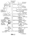
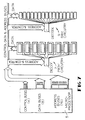
- Figures 1Aand 1 C are front and side views, respectively, of a preferred apparatus console or housing H with panels removed to expose the interior, and Figure 1B illustrates a top view.
- a time card is shown at T inserted within a top surface slot and card assembly guide 2, past a photosensitive transistor sensor block or similar reading line or sensor array 17, more fully discussed in connection with Figures 6A and B, and cooperative with a mark-sense electronic circuit later also delineated in detail.
- the card T is shown extending into a printer region 19 comprising a print character drum cooperative with opposing solenoid-controlled impact hammer means later described, and with the lower end of the card operated upon by a card clamping or grabbing solenoid.
- a power supply 1 and standby battery source 3 for keeping up the random access memory for the system may conveniently be disposed on one side at the lower levels of the console H, with the microcomputer circuit boards 5 mounted along the other side of the console.
- the later-described electronic boards 29, 29' for the optics, printing and keyboard and display, and the loud speaker 31 for audio response when the keyboard is operated or when an indication of improper operation is to be signalled, may be mounted within the upper section of the console H below the top panel.
- the side view of Figure 1C also shows the mother-board construction 21' containing all the interconnections from the various printed circuit boards 5 that plug into the same.
- the keyboard 27 need not be located on an external surface of the console.
- the keyboard 27 may be disposed within the console, accessible through a door or panel to prevent undesired use or abuse; or the same may be internally disposed as a movable sub-assembly connected to its electronics via a flexible cable, so that the operator can open up the console and access the keyboard to enter whatever information is desired and then may reinsert it back into the console.
- the before-described power supply 1 may receive ac voltage available in the office, such as 115 or 220 volts, generating the necessary ac end dc voltages and currents needed by the various parts of the device.
- ac voltage available in the office such as 115 or 220 volts
- the previously mentioned back-up battery 3 which normally is not in use and is just being charged from the primary source, will serve to keep operational certain key parts of the device; namely, the microprocessor 5 and the random access memory.
- a suitable microprocessor for the purposes of the invention is, for example, the Z80, as described in the February, 1977 Mostek Corporation Z80 Technical Manual.
- Other parts of the device, such as the printer 19 and display 11 are not powered from this emergency source because it is presumed that the device will not be used in normal mode at such time; but it is vital to keep memory from being lost, and specifically the random access memory.
- the microprocessor 5 Two kinds of memory are herein used the microprocessor 5; first, a program memory 7 (PROM), and also the before-mentioned random access dynamic memory 9 (RAM).
- the program memory 7 the firm ware is stored; that is, a control logic executed by the microprocessor 5 to generate the appropriate command sequences such as are required to read the card T, print on the card, process the keyboard 27, etc.
- the data storage memory 9 on the other hand, the information obtained from reading the time cards T or information obtained from initializing the time clock with, for example, the parameters of when a person can enter and leave and like data, is stored. All data stored at 9 is held for use in, for example, a larger payroll processing computer elsewhere, with this information transmittable by phone-line to either a central holding computer or to a payroll processing computer by means of external communications, as through the modem 25.
- numeric display 11 is used to indicate the time of the day, and to give a feedback to operator, for example, when it is being initialized and the operator is entering the date or the time in this numeric display.
- a 6-digit LED type display is shown for illustrative purposes.
- the four malfunction lights 13 may be incandescent bulbs or LED indicators or the like to indicate some abnormal operation of the clock such as, for example, that the card is not read properly, or that a person is putting in a time card T which indicates that such person should not be punching in at this time, or that something has gone wrong in the clock that requires servicing.
- a card detector 15 is provided, which detects the time card T as it is being inserted into the time clock guide 2.
- This card detector can be of one of two types. It can be a photo-transistor and LED or similar combination connected for transmission of light to the photo-transistor; or it can be of the reflective type wherein the insertion of a card causes this light to be reflected from the source into the photo-transistor, where otherwise it would not be so reflected. In either case, the detector 15 alerts the electronics to the fact that a card is entering or that a card is still in the machine; and it will so indicate that state until the card is removed.
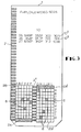
- the time card T consists of various components, later more fully discussed, including a longitudinal margin set of clock track marks 2' ( Figure 3) used for determining the position of the card relative to the printer 19 and in particular to the line to be printed. There is also a central lower clock-track 2" in the data field 6 which indicates the number of the row being read.
- the data field 6 is the area where information is mark-sensed on the card.
- the print area 10 ( Figure 3) is the upper area on the card T upon which the information that is outputted from the time-clock to the person using the card is printed.
- the time card T is shown exposed to the mark-sense detector 17 that actually reads the information in the data field 6 of the card T and converts the same into a form useable by standard microprocessors 5.
- the printer 19, particularly designed for printing on cards, may be of various types such as a drum printer or a matrix-printer.
- loud speaker 31 has been before described for giving an audio indication of improper operation, or to alert the operator that something is unusual or requires attention, such indication need not be given by a loud speaker.
- Other warning devices, piezo-electric resonators, etc. may also be used.
- this keyboard enters information in initializing the clock, including setting up the correct time and date, the pay period endings and the like. It is also used at other times by a supervisor or operator to input specific commands to the clock, such as changing or entering something which would not normally be permitted, or requesting a summary of information in the clock. It is also used by maintenance personnel in requesting tests of various specific functions of the components inside the clock. For example, maintenance personnel could use the keyboard to turn the printer on and off to make sure that it is working.
- keyboards could use the keyboard to request that a specific line of print be printed on a card, or to request a check of memory by having the computer write a known thing into and out of each address, or to check out the whole operation by speeding up the time, say ten times or one hundred times faster than normally, so that the maintenance personnel can check that the algorithms are being executed in the expected manner.
- the external communication has been previously mentioned in connection with the modem 25 to enable the clock to transmit its data to a payroll processing computer or some central holding computer.
- the external communications port may, for example, consist of RS232C interface, modem, and data access arrangement that will automatically answer the telephone when it rings in order to establish a two-way telephone communication.
- the internal communications port comprises a frequency-shift keyer (FSK) to provide tones which represent the digital signals, enabling one clock to communicate with another clock.
- FSK frequency-shift keyer
- the time card uses longitudinal margin track marks 2', shown on the left edge although the opposite edge could also be used.
- the clock-track 2' enables determinatian of the position of the card relative to the print line adjacent the particular clock-track mark 2'.
- the parallel marks are preferably equally spaced as illustrated.
- the interior or central similar clack-track 2" preferably divides the two halves of the data field 6, increasing by two the amount of skew which the card can tolerate and still be able to read accurately the inserted data such as the pencilled blocks 8 in the data field 6.
- the remaining component of the card T is the area 10 on which the information is printed, as shown at printed lines 10", 10"', etc.
- a typical line of print 10 may consist of the following: the date, for example, the 26th day of the month; the time at which the employee punched in, for example, 12:49 pm; the time at which the employee punched out, for example, 3:52 pm; the total number of hours credited with working so far this day, for example, 3 hours and 3 minutes.
- the daily working time may be somewhat different than just subtracting the difference of the time at which the employee punched in, from the time at which the employee punched out, because each employer may have rules that penalize employees for arriving late, or rewards for employees arriving early, or the like.
- the last item on the line may be the total amount of time worked so far that week, for example, 3 hours and 3 minutes this week.
- each data field 6 is a start code, shown at the left-hand side as the all black line 2A, the right-hand side all white start code 2B'.
- the micro-computer expects to see on the left side, for example, the black start code 2A; and then it expects to see ten data rows and then the upper left-hand white stop code 2B. In that period, there is a fixed number of clock-tracks which it must count; in this case, twelve.
- the computer When the computer reads a card, therefore, it looks at the two darkest marks in a column and checks to see that one is the start code 2A, whence the other is the desired mark. If one of those marks is not, however, the start field code 2A, and if the last row read is not the white code 2B, the computer rejects this and responds appropriately; in this case, generating a sound in the speaker 31 and causing one of the abnormal function indicator lights 13 to become lit. In such case, it is requested that the card be re-inserted.
- the employee's number is marked into the data field 6.
- the card in Figure 3 shows an eight-digit employee number, 63659026.
- a check sum digit in the last column of the employee's number may be used.
- the last digit 6 is electronically computed from the first seven digits; and in fact the time clock checks that digit by comparing what it read to what it computes in the first seven, only accepting the card as properly identified with the employee user when the number it computes matches the number it reads.
- the employee With the employee number precoded onto the card, the employee inserts the same into the guide 2, Figure 1A, and as he inserts it, the data field 6 passes through the mark-sense detector 17, Figure 2.
- the mark-sense detector electronically reads and extracts the information from the card and the computer then refers to this employee's previous identification and other information electronically stored in the data storage memory and computes what line is to be printed next.
- a clock-track detector counts the number of clock-tracks 2' that have passed, and when the same gets to the line which is to be printed, a card grabbing solenoid (which is part of the card printer assembly 19) grabs or clamps the card and holds it firmly, and, for example, the day of the month and the time of the punching-in will be printed, as at 10". At that point, the card-grabbing mechanism will release and the employee is free to pull the card out of the system. The machine will know when the card is out of the device because the card detector 15 will so indicate, such that the apparatus is now ready to receive the next card.
- the rules governing the employee's shift may not permit the employee to punch in at that particular time. If this happens, the time-clock does nothing; it does not grab the card and it does not print on the card. It does, however, display an illegal or improper entry indication on an abnormal function indicator lamp 13.
- the employee may forget to punch out. Let us say that the employee punched in at 1:52 pm on the 26th, and came back at 2:56 pm on the 27th.
- the clock realizing that more than 16 hours had passed, which is the rule for determining a missing punch for this particular shift, would not then try to punch the employee out at that time. Instead, the clock may indicate a missing punch in the area where it would normally have punched out, and would proceed to the next line and punch the employee in on the 27th at 2:56 pm, considering that a punch-in.
- Another card may be used for maintenance, allowing an installation repairman access to certain software routines which are useful in determining what may be malfunctioning.
- the maintenance card number will activate the keyboard 27, causing the keyboard to light up and making the same available for entering commands to test the various components inside the apparatus, as later more fully explained.
- FIG. 4 contains legends explaining the control function.
- the micro-processor 5 in addition to keeping track of time and displaying, is constantly looking for the insertion of a card into the card reader or mark-sense detector 17. If a time card time T is inserted and is detected by the card detector 15, then the data on the card is read. The alternative is thatthere is no card in the card reader and the card detector 15 has thus not detected anything; in which case, the computer looks to see if there are any requests for either internal or external communications, as at 25 and 23, Figure 2. If there is such, the requests are processed and the computer returns to looking for a card being inserted into the reader.
- the processor must then determine whether this is a good card, by looking at the start and stop code marks 2A, 2B, etc. in relation to the twelve middle clock tracks 2" on the card T, as before described in connection with Figure 3. If this was not a good card read, then the processor generates a trouble signal on loudspeaker 31 to alert the user that the card was not read, and activates a trouble indicator light 13, lighting the legend "reinsert card” so the user knows to remove the card and reinsert the same, with the control logic waiting until the card has been removed before returning to looking for the insertion of a card in the reader.
- the processor must next determine what kind of card it is. It could, for example, be one of three types of cards. It could be an employee card; it could be a supervisor or operator mode card; or it could be a maintenance mode card.
- the processor knows if it is an employee card by the check digit at the end, as before described, since the supervisory mode card and maintenance mode card are particular numbers in which their eighth digit is not a check digit as in the case of an employee number. If none of these cards is recognized, the computer lights the illegal entry lamp and waits far the card to be removed from the reader before returning to normal processing.
- the keyboard 27 is activated, as before explained, and the computer search is for either a legal operator mode command, or a maintenance mode command, respectively.
- the processor looks at the command to determine first if such is an exit command, meaning exit from either supervisor or maintenance mode. If it is an exit command, the keyboard 27 is de-activated, the light underneath the keyboard is extinguished, and processing goes back to looking for the insertion of another card into the reader. Should the command not be an exit command, then whatever it is, is processed; and the computer resumes searching for other commands until it receives an exit command.
- the processor searches the employee file stored in the data storage memory 9, and computes the next line of the card which is to be printed. After that computation is made, it counts clock-tracks 2' until the next print line is reached, and the computer also determines whether or not the employee is allowed to punch in at this time. If the employee is not allowed to punch in at this time, the computer lights the illegal entry indicator 13 and waits until the card has been removed from the reader, then resumes looking for another card to be inserted into the reader. If the employee is allowed to punch in at this time, however, the card is grabbed at the computed print line, and then the processor must determine whether the employee is punching in or punching out.
- the printer prints the day of the month on the card and it prints the current time and stores the information in data storage memory 9. Then, it releases the time card T from the printer 19 and waits until the card has been removed from the reader before it resumes looking for a card to be inserted. If the employee is punching out, on the other hand, the computer will cause the punch-out time to be printed on the card and it will store the punch-out time in the data storage memory 9, computing and printing the total time worked so far that day and, in addition, the total time worked so far that week. When that is completed, the time card will be released from the printer 19 and the processor will wait until the card has been removed before returning to searching for the insertion of another card.
- the first type commands change or alters data in some way; and the second requests reports or summaries of the data in the clock.
- Examples of the former are commands to change the time of day, change the date, duplicate an employee's time card because it has been lost, authorize an employee to punch in when the employee would normally be prohibited from punching in, etc.
- Examples of the second kind of commands are asking for summaries of information from the clock such as a listing of all employees and how many hours they have worked so far this week or this day; or a summary of all the employees who punched in late; or a summary of employees who have not punched in at all today and are absent; or a summary of employees who have worked more than some specified number of hours, etc.
- the system When the system computes the last digit on the supervisory card and finds that it does not match the last digit on the card, it looks through a table of special numbers, one of which is the supervisory or operator mode access code. Finding that the number on the code is the operator mode access code, the firmware causes the keyboard 27 to be illuminated and scans the keys for input commands.
- the keyboard command to change the time is * , 1, ENT.
- the operator After entering this command, the operator enters the time on the keyboard (e.g. 1245A). Assuming no other corrections, commands, reports, etc. are required, the operator then returns the clock to its normal operating mode by entering * , 0, ENT on the keyboard. This deactivates the keyboard 27 and causes the time to appear in the numeric display 11.
- the card of the invention operating as a secure switch to enable the operator or supervisor to switch modes, and similarly the maintenance or diagnostic personnel to switch from normal operation to a diagnostic mode, as distinguished from mere key switches for changing from normal operation to the respective operator-supervisor or diagnostic modes.
- the invention enables a print out, for example, of the particular maintenance routine that has been performed, providing a permanent record thereof.
- a further advantage resides in the fact that either pre-recorded instructions on the card can be entered directly through the use of the card, or the keyboard may be employed for providing commands, or a combination of these techniques is available.
- the timeclock firmware includes a set of diagnostic routines designed to assist the repair and maintenance of the unit. These routines are accessible only when the clock is operated in its maintenance mode. One such routine enables three keys on the keyboard even after the clock has been returned to its normal operating mode. These three keys are used to speed up the rate at which time on the clock increments. The first key speeds up time by a factor of 60, the second by a factor of 600, and the third key restores it to its original rate.
- the repairman inserts a maintenance mode access card which illuminates and activates the keyboard.
- the repairman then uses the keyboard to enter the speedup command.
- this is * , 5, ENT, for example. He then exits the command mode by entering * , 0, ENT. This will cause the keyboard illumination to cease and the keyboard will be partially deactivated.
- the clock will operate in its normal manner and will display the time of day, incrementing 1 minute each minute. However, if the "4" key is pressed, the time display at 11 will speed up, incrementing 1 minute each second. Pressing the "7" key will cause the time display to increment 10 minutes each second; and pressing the "1 key will cause the time display to return to its original rate, incrementing 1 minute each minute.
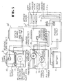
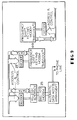
- Figure 5 shows how the various sub-assemblies are electrically connected, being particularly concerned with the subassemblies associated with the mark-sense detector or card reader 17 (namely, the card guide assembly 20 and the printer assembly (P.A.)19). and with the parts exploded and placed side-by-side and in cross-reference positions for explanatory purposes only.
- the before-mentioned means for clamping and immobilizing the card at the appropriate point labelled "Card Clamp Solenoid" in the card guide assembly 20 of Figure 5, is connected to the electronics located on a printer interface board 29, so-labelled, connected through plug P4 thereof.
- the previously described card detector 15 ( Figure 2) is mounted upon the printer assembly 19, being connected to plug P6 of the so-called optics board 29', containing all the electronics relating to the optical operation of the device.
- the sensor or card-reading black 17 ( Figure 2) which does the actual detection of the data in clock-tracks 2' of the cards T is shown mounted on the printer assembly and is connected via plug P7 to the optics boards 29'.
- Asuitable printer for the purposes of the invention is the Model DTP9 manufactured by Practical Automation Company.
- the various operations of this type of printer 19 and similar printers are (1) activating the solenoids of the printer head that produce the dots via plug P5 to the printer interface board 29; and (2) moving the array of dot-making solenoids laterally by a stepping motor referred to as the printer "head motor”, controlled by connection to plug P1 of the printer interface board 29.
- the printer 19 also contains a photodetector or other detector, labelled “printer head detect”, for detecting when the printer head has reached the end of the line and needs to be re-positioned at the beginning of the line, being shown connected to plug P3 on the printer interface board 29.
- Figure 5 also shows how the before-mentioned battery 3 and power supply 1 are connected to the mother-board 21', Figure 1C.
- the ribbon advance motor for the printer is shown connected to plug P2 of the printer interface board 29, and is used to advance the ribbon during the printing, for wear considerations.
- the CPU (central processing unit) board contains the microprocessor 5 and the program memory (PROM) 7 of Figure 2, and is located on the mother board 21' alongside the random access memory board 9 for data storage. Above those is shown the location of the optics board 29' containing the electronics used to read the information off the card, and above that is the printer interface board 29 which contains the electronics needed to drive the various above-mentioned functions of the printer. Above these is a board labelled "DSKY" that has the electronics to drive the display and to decode the keys on the keyboard 27, Figure 1A-C.
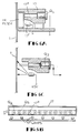
- a suitable optics sensor assembly, array or block 17 for mark-sense reading of the information on the card is detailed in Figures 6A and B, with an array of lamps 17' mounted on a board to illuminate a particular area of the card, preferably through a green-glass filter or the like to filter out the large amount of infrared spectrum.
- the phototransistor array is exposed through openings 17" to a restricted field of view corresponding to that area on which marks would be put onto the card; the phototransistors either seeing a significant amount of reflected visible light if the card is basically white or unmarked, or a very small amount of light if the card has been marked with a black box that absorbs, as distinguished from reflecting the light.
- Figures 7, 8 and 9 show how the components of the electronics are electrically connected and controlled by the microprocessor 5, which, as is well known, has an architecture comprising address, data, and control busses.
- the data bus is shown in Figure 7 as provided with eight lines to transfer its data, eight bits at a time.
- the address system is a 16-bit address bus permitting the addressing of up to 64384 words of memory; and the control bus is shown as a 4-line control.
- the microprocessor busses are interfaced to the PROM 7 ( Figure 2) containing the program instructions with the address and control lines connected to standard decode circuitry, and the data bus connecting directly to the appropriate lines on the PROM to read data out into the microprocessor.
- the random access memory circuit 9 (RAM), is also shown in Figure 7 even though this is physically located on a different board than the CPU and PROM as previously described in connection with Figure 5.
- the decoding of the addresses is done in a fashion similar to that of the PROM and again the data lines are connected directly to read the data into the microprocessor 5 and to write data from the microprocessor into the RAM 9.
- Such bi-directional data flow is indicated in Figure 7 by the opposite arrows at "DATA" at the RAM circuitry 9, as opposed to the PROM which is uni-directional, as indicated by the single arrow "DATA" thereabove.
- Figure 8 is an extension of the busses of Figure 7, showing how they interface to other sub-assemblies of the time-clock including the printer 19, the keyboard 27, the clock-track detector and the mark-sense circuit 17. Again, the indicated decoding is by standard well-known technique. Suitable specific circuitry for the printer 19, the keyboard 27 and clock-track and mark-sense 17 are hereinafter described in connection with respective Figures 10, 11, 12 and 13.
- Figure 9 is a further extension of the bus structure of Figure 8, showing an interface to the communications circuitry 23 and 25 discussed earlier in connection with Figure 2.
- interfacing may be effected by an RS-232C type interface, in turn connected with a modem of, for example, the Bell 103 (or similar Vadek Corporation Modem-1976 bulletin "Why Modems").
- the Bell 103 or similar Vadek Corporation Modem-1976 bulletin "Why Modems"
- the actual interconnecting to the telephone lines is made via a DAA(data access arrangement).
- the Bell Telephone Company for automatically answering the telephone lines (suitable Bell model numbers being listed, such as the CBS1001AorF, or the CBT 1001 B or D).
- the first task is the synchronization of all the timeclocks, as by having one time clock tell the other time clocks what time it is.
- Another purpose for this internal communications is to enable many time clocks to talk to the same central computer via the telephone line, but avoiding problems such as time clashes, etc.
- one clock (#1) is shown connected to another time clock (#2) with the aid of well-known frequency-shift keying modulators at 23.
- printer circuitry 19 keyboard circuitry 27, and clock track and mark-sense circuitry 17 for the practice of the invention.
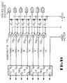
- FIG. 10 A preferred printer circuitry 19 is illustrated in Figure 10 for controlling the actual printer mechanism earlier described in connection with Figure 5.
- Figure 10 shows seven input data lines Do-D s connected through buffers U3 and U4 to drive respective transistars TR1-7 which in turn are connected to each of the seven solenoids S1-S7 controlling seven dots in the dot markers of the printer head.
- the last line D7 is used to supply power to the head motor that drives the head across the print line as described in the embodiment of Figure 5.
- Diodes R'1-R'7 shown connected across the solenoids S1-S7, are used to prevent improper negative voltages, occurring as a result of solenoid magnet current drive, from destroying the drive transistors.
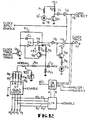
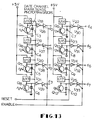
- FIG 11 a schematic diagram of a suitable capacitive keyboard 27 is shown, with the keys represented by capacitors.
- the signal from a square wave oscillator (say 80 KhZ) that goes through the capacitors of the keyboard is normally in phase with the signal that does not go through the keyboard.
- the free-running 80Khz square wave oscillator signal is applied to the input of a buffer U3A for buffering.
- U3B returns the phase, ⁇ , to 0°.
- This buffered signal is then applied to the inputs of: analog multiplexers U10 and U11; input-a-of exclusive-OR U6; and to the gate ofQ1.
- Outputs 0-7 of U11 are successively selected while U10 is inhibited; then outputs 0-7 of U10 are successively selected while U11 is inhibited.
- This addressing process is repeated until the data is detected at D o ', indicating a character has been selected. The addressing process begins again after data has been entered.
- U6A performs the indicated exclusive-OR function and in this case (Mode I), the output is (3) as shown; i.e., (1) at the sum node produces (3) at the exclusive-OR output.
- U6A output (3) appears noisy due to slight phase shifting of U6A input b. This arises from additional gate delays along that signal path.
- Delay ⁇ is used for reducing the "spikes” to below threshold values, and is about 5mS.
- U6B is used for buffering to U4.
- U4 gates the data (in this case "0") with KEYWR-L. Since no data was present, the selection process addresses the next character to "see” if it has been selected.
- This calibration takes plake automatically via hardware-DAC-software interfacing.
- the invention provides a novel mark-sense reader that reliably distinguishes intentional marks from accidental marks, such as dirt, finger prints, etc., and additionally meets cost constraints with efficient use of microcomputer components required for other purposes.
- prior mark-sense readers employ threshold-operated comparator circuits in which the transition threshold from dark to light is absolute. If an unintentional mark is darker than the threshold, or an intentional mark is lighter than the threshold, such will be misinterpreted.
- threshold-operated comparator circuits in which the transition threshold from dark to light is absolute. If an unintentional mark is darker than the threshold, or an intentional mark is lighter than the threshold, such will be misinterpreted.
- opposing plastic guides 2 preferably of black light-absorbing material, are used to direct and align the card T as it is pushed down in front of the line or block of phototransistors 17, labelled in Figure 6B with notations Q5, Q6, etc., to correlate with the phototransistors in the circuit diagram of Figure 13.
- the field of view of the phototransistors is limited to an area corresponding to the individual mark-sense blocks or spaces in the data region 6 on the time card T, Figure 3.
- the light generated from the lamps 17' is thus either mostly absorbed by a black mark or mostly reflected by the white card; and the presence or absence of this light is detected by each of the phototransistors.
- the mark-sense detector cannot distinguish a black mark on the time card from the condition of the non-existence of a time card.
- the card-detector LED light source and phototransistor 15 of Figure 2 is therefore provided, to be activated by the reflection of tight from the card (though transmission could also be used), thus to enable an unambiguous determination of the presence or absence of a card.
- the light-emitting diode D1'and phototransistor Q1 comprise the before-mentioned card-detect circuit 15 of Figure 2.
- the voltage at the collector of Q1 is high when a time card is in the mark-sense reader and becomes low when the card is removed.
- Inverter U1 is used to sharpen the transition of this waveform, and connects with a buffer U2, the outputs of which are enabled by a "clock input enable" signal. When not enabled, the output of U2 is in a high impedance state, thereby isolating the card-enable circuit from the data line d6 of the microprocessor 5.
- Q2 is the phototransistor of the array that detects the light reflected from the clock track marks 2', Figures 3, 6C, and its sensitivity is determined by the amount of current provided to the collector of Q2 from a constant- current source consisting of Q3 and resistor network R4, R5, R13, and R11. Diode D2, connected between R4 and R5, is provided for temperature compensation, while a capacitor C2 is provided at the junction of R5-R11-R13, to limit high frequency response.
- the amount of current sourced by Q3 is determined by the voltage divider formed by resistors R5 and R13 in parallel with a combination of R7, R8, R9 and R10.
- resistors are tied to the microprocessor data lines d0, d1, d2 and d3 through respective four latches U7 A-U7D.
- the data line also connect with latches U9 controlling the printer operation through U8 also inputted from card detect and clock track lines d6 and d7.
- the outputting of a logical "zero" on a data line and enabling of latch U7 grounds the corresponding resistor; i.e. puts it in parallel with R13, thereby decreasing the effective resistance of the resistor network.
- a logical "one" on any of the data lines d0-d3, however, will produce the opposite effect; i.e. it increases the effective resistance of the network.
- the sensitivity of the clock track phototransistor Q2 therefore can be controlled by the program in the microprocessor 5.
- Capacitor C1 limits the high frequency response and resistor R3 provides hysteresis to increase noise immunity by spreading the positive and negative going transition levels.
- Buffers U3 and U4 are shown respectively provided across C1 and in series across R3, with U4 connecting to buffer U5 feeding the base of later-described Q4 and buffer U6.
- Transistor Q4 sources current to LED D3, through a current-limiting resistor R6, to provide a visual indication of the performance of the card detector sensor for diagnostic purposes.
- the base of Q4 connects with a buffer U6 with tri-states outputs identical to U2.
- the microprocessor 5 operates the clock track detector in the following manner. In normal condition, the card detect interrupt is enabled, such that when a card T is inserted, the microprocessor receives an interrupt indicating that the signal on data line d7 is black (because the plastic card guide 3 is black). The microprocessor then immediately calibrates to black, before the white card reaches clock track phototransistor Q2, by first pulling resistors R7-R10 high by means of latch U7. This causes the output on d7 to indicate black.
- Parallel resistor combinations of R7-R10 are then sequentially pulled low (in order of decreasing effective pull-down resistance) until the output on d7 corresponds to white. At this point, the effective resistance is increased until the output on d7 returns to the black state at a level just above that needed to transition to white.
- the operation is now in condition for the card edge to pass phototransistor Q2. This is indicated by output d7 transitioning from black to white.
- the circuit now increases the effective pull-down resistance of the parallel combinations of resistors R7-R10 until the output on d7 indicates black. At such a time, the effective pull-down resistance is decreased until the output on d7 returns to a white state at a level just below that needed to transition to black.
- This sensitivity setting may be called the "white sensitivity”.
- the reaching of phototransistor Q2 by the block calibration mark is now awaited.
- the computer now decreases the effective pull down resistance until d7 indicates white and then backs off until d7 returns to a black state just above that needed to transition to white. This setting may be called the "black sensitivity”.
- the computer calculates the clock track threshold to be approximately halfway between the black sensitivity and the white sensitivity and then causes U7 to implement a resistor combination corresponding to this value.
- the data channel mark-sense detectors Q5, Q6, etc. operate differently, in accordance with the invention, from the clock track circuit of Figure 12.
- the schematic diagram of the data channel mark-sense detectors is shown in Figure 13.
- the phototransistors Q5-Q12 correspond to the array 17 of Figure 6B.
- Each phototransistor is associated with a CMOS bilaterial switch (such as types 4016's or 4066's), labelled U10-U17 to correspond with respective phototransistors Q5-Q12.
- the bilateral switches U10-U17 are activated by means of the "reset" line when initiated by the clock track interrupt, thereby allowing respective capacitors C3-C10, connected between emitters and collectors of respective phototransistors Q5-Q12, to charge.
- switches U10-U17 are deactivated.
- the phototransistors Q5-Q12 will then discharge their respective capacitors C3-C10 at different rates, proportioned to the amount of light incident upon them.
- Those phototransistors receiving more light will have a lower collector-to-emitter impedance and will discharge their corresponding capacitors at a higher rate.
- Buffers U18-U25 are respectively connected to capacitors C3-C10 to sharpen the waveforms into negative-going edges that transition when the capacitors are about half discharged.
- Tri-state latches U26-U33 respectively connected to buffers U18-U25, and the corresponding output data tines d0-d7 are read by the microprocessor 5. Initially, there will be “1's” on all of the data lines because the capacitors have not had sufficient time to discharge. The reading process is repeated until one of the data lines transitions from high to low. The resulting data word is stored in memory along with the total number of reads made by the microprocessor up to the occurrence of this transition. The reading process is then continued, storing the data word and the read number (which corresponds to the decay time) each time a transition occurs on one of the data lines. When all of the data lines have transitioned to the low state, the reading of this mark-sense row or line is terminated.
- the next row or transverse line of mark-sense data is similarly read. This process is repeated twelve times, corresponding to rows or lines for the start code 2A, stop code 2B and 10 digits for the format 6 of the card T of Figure 3, as before explained.
- the microprocessor in conventional manner, now sorts the data, which was stored by rows, into a column format. For each of the 12 entries in each column, the decay times are compared and the entries corresponding to the two longest decay times are selected. Since operation in accordance with the invention requires one and only one intentional data mark in each column in the mark-sense field 6 of the time card T, one of the entries selected by the microprocessor must be either the start code or stop code (depending upn the column). If, however, neither mark selected corresponds to the correct start or stop code, the reading of this card is considered to have been unsuccessful; and the appropriate responses are initiated by the microprocessor.
- the software structure consists of three prioritized levels of external I/O functions.
- the highest priroity functions are the following three versions of the 60-cycle interrupt handler. One version is used if the interrupt occurs while the control program is executing the initialization routine.
- the second, is the normal 60-cycle interrupt handler which updates both the time data and the display, as well as operating the bell schedule; and the third is used if an interrupt occurs while reading a time card, and it just updates the time data.
- the next priority level processes interrupts generated by the card-detect sensor 15, clock track detector Q 2 , etc., and printer timing pulses. These interrups are maskable, and should a 60-cycle interrupt be received while processing these functions, they are themselves interrupted and execution of the fast (3rd) version of the 60-cycle interrupt functions is then completed.
- the type Z-80 microprocessor for example, has been found fast enough to complete the execution of both the maskable and unmask- able routines in the required amount of time, even for reading clock tracks.
- the lowest priority level is given to the scanning of the keyboard 27, handling communications between multiple clocks on a single system at 23, Figures 2 and 9, and handling communications between the clock and the central payroll processing computer as at 25.
- This function is processed by having the computer cycle through the appropriate I/O ports until it is interrupted by a priority 1 or 2 function.
- the invention accordingly, not only provides the flexibility for automating employee time and attendance records, and in format directly useable by and transmitted to payroll processing or other computers, but provides the flexibility for entering additional data and revisions without the need for custom programming, and accomplishes all these ends with the added advantage of the use of a simple time card and any convenient marking means.
Landscapes
- Physics & Mathematics (AREA)
- General Physics & Mathematics (AREA)
- Time Recorders, Dirve Recorders, Access Control (AREA)
Claims (24)
Priority Applications (3)
| Application Number | Priority Date | Filing Date | Title |
|---|---|---|---|
| AT79301449T ATE23070T1 (de) | 1979-03-13 | 1979-07-20 | Verfahren und vorrichtung zur registrierung der zeit. |
| DE8383100805T DE2967671D1 (en) | 1979-03-13 | 1979-07-20 | Apparatus for time clock recording and computation |
| AT83100805T ATE31828T1 (de) | 1979-03-13 | 1979-07-20 | Geraet zur registrierung und berechnung von anwesenheitszeiten. |
Applications Claiming Priority (2)
| Application Number | Priority Date | Filing Date | Title |
|---|---|---|---|
| US20223 | 1979-03-13 | ||
| US06/020,223 US4270043A (en) | 1979-03-13 | 1979-03-13 | Methods of and apparatus for time clock recording and computation and related uses |
Related Child Applications (1)
| Application Number | Title | Priority Date | Filing Date |
|---|---|---|---|
| EP83100805.7 Division-Into | 1983-01-28 |
Publications (4)
| Publication Number | Publication Date |
|---|---|
| EP0016276A2 EP0016276A2 (fr) | 1980-10-01 |
| EP0016276A3 EP0016276A3 (en) | 1983-01-12 |
| EP0016276B1 EP0016276B1 (fr) | 1986-10-22 |
| EP0016276B2 true EP0016276B2 (fr) | 1993-04-28 |
Family
ID=21797413
Family Applications (2)
| Application Number | Title | Priority Date | Filing Date |
|---|---|---|---|
| EP83100805A Expired EP0083564B1 (fr) | 1979-03-13 | 1979-07-20 | Dispositif pour l'enregistrement et le calcul du temps de présence |
| EP79301449A Expired - Lifetime EP0016276B2 (fr) | 1979-03-13 | 1979-07-20 | Méthode et dispositif pour l'enregistrement du temps |
Family Applications Before (1)
| Application Number | Title | Priority Date | Filing Date |
|---|---|---|---|
| EP83100805A Expired EP0083564B1 (fr) | 1979-03-13 | 1979-07-20 | Dispositif pour l'enregistrement et le calcul du temps de présence |
Country Status (11)
| Country | Link |
|---|---|
| US (1) | US4270043A (fr) |
| EP (2) | EP0083564B1 (fr) |
| JP (1) | JPS55124885A (fr) |
| AR (1) | AR229016A1 (fr) |
| AU (2) | AU535119B2 (fr) |
| BR (1) | BR8001458A (fr) |
| CA (1) | CA1134041A (fr) |
| DE (1) | DE2967631D1 (fr) |
| HK (1) | HK20089A (fr) |
| IN (1) | IN158457B (fr) |
| MX (1) | MX149932A (fr) |
Families Citing this family (57)
| Publication number | Priority date | Publication date | Assignee | Title |
|---|---|---|---|---|
| IE49679B1 (en) * | 1979-06-01 | 1985-11-27 | Itr Int Time Ltd | Time recorder |
| SE424926B (sv) * | 1980-01-25 | 1982-08-16 | Bille Dag Svensk Ideutveckling | Tids- och hendelseregistrator for registrering, behandling och dokumentering av varaktigheten av skilda kategorier arbetsprestationer |
| JPS6127015Y2 (fr) * | 1980-05-02 | 1986-08-12 | ||
| JPS56159781A (en) * | 1980-05-12 | 1981-12-09 | Amano Corp | Time recorder |
| JPS56159782A (en) * | 1980-05-12 | 1981-12-09 | Amano Corp | Time recorder |
| JPS56164487A (en) * | 1980-05-20 | 1981-12-17 | Amano Corp | Time recorder |
| JPS5775388A (en) * | 1980-10-28 | 1982-05-11 | Casio Computer Co Ltd | Electronic time recorder |
| JPS5775387A (en) * | 1980-10-28 | 1982-05-11 | Casio Computer Co Ltd | Miniature electronic equipment |
| US4361092A (en) * | 1980-12-12 | 1982-11-30 | Kronos, Incorporated | Process and apparatus for time card preparation and utilization and the like |
| CA1174763A (fr) * | 1981-01-22 | 1984-09-18 | Alan G. Witts | Enregistreurs pour l'enregistrement de donnees |
| DE3111353C2 (de) * | 1981-03-23 | 1984-09-13 | Hermann 7742 St Georgen Stockburger | Datenverarbeitungsvorrichtung |
| US4445181A (en) * | 1981-06-02 | 1984-04-24 | Teoman Yatman | Meeting cost calculator and/or timer |
| JPS583087A (ja) * | 1981-06-30 | 1983-01-08 | アマノ株式会社 | パ−トタイマ−等用賃金積算レコ−ダ−装置 |
| JPS5824962A (ja) * | 1981-08-06 | 1983-02-15 | Dainippon Printing Co Ltd | 工票読取集計装置 |
| EP0105594A3 (fr) * | 1982-08-27 | 1986-01-15 | FIGGIE INTERNATIONAL INC. (Delaware Corporation) | Lecteur de cartes pour système de sécurité |
| EP0107291A3 (fr) * | 1982-08-27 | 1986-01-22 | FIGGIE INTERNATIONAL INC. (Delaware Corporation) | Lecteur de cartes pour système de sécurité |
| US4544832A (en) * | 1982-08-27 | 1985-10-01 | Figgie International, Inc. | Card reader with buffer for degraded mode |
| DE3381363D1 (de) * | 1982-08-27 | 1990-04-26 | Figgie Int Inc | Kartenleser fuer sicherheitssystem. |
| US4524266A (en) * | 1982-09-13 | 1985-06-18 | Kronos, Inc. | Method of and apparatus for discriminating between various types of check-out periods in employee time-recording systems and the like |
| US4494127A (en) * | 1982-09-13 | 1985-01-15 | Sci Systems, Inc. | Apparatus and method for recording both machine-readable and printed information |
| US4506274A (en) * | 1982-09-24 | 1985-03-19 | Sci Systems, Inc. | Time card recorder and method for identifying employee work schedule |
| US4816658A (en) * | 1983-01-10 | 1989-03-28 | Casi-Rusco, Inc. | Card reader for security system |
| DE3306681C1 (de) * | 1983-02-25 | 1983-12-15 | Telefonbau Und Normalzeit Gmbh, 6000 Frankfurt | Verfahren zur Gleitzeiterfassung mit Hilfe eines Fernsprechapparates |
| US4567357A (en) * | 1983-05-06 | 1986-01-28 | Kronos Incorporated | Method of and apparatus for automatic line identification for recording on employee time cards and the like |
| US4536646A (en) * | 1983-06-16 | 1985-08-20 | Celedata Corporation | Time accounting system |
| IT1163550B (it) * | 1983-06-21 | 1987-04-08 | Solari & C Spa | Orologio per la timbratura schede di presenza |
| SE440287B (sv) * | 1983-11-28 | 1985-07-22 | Kurt Paulsson | Anordning vid ett terminalsystem |
| JPS61226889A (ja) * | 1985-03-31 | 1986-10-08 | マックス株式会社 | タイムレコ−ダ |
| US4819162A (en) * | 1985-05-17 | 1989-04-04 | Time Management Corporation | Time clock system including scheduling payroll and productivity analysis capability |
| EP0223353A3 (en) * | 1985-09-10 | 1988-07-20 | Canon Kabushiki Kaisha | Information record carrier |
| US4751521A (en) * | 1985-09-24 | 1988-06-14 | Seikosha Co., Ltd. | Time recorder with automatic correction for momentary discontinuation of power supply |
| CA1291565C (fr) * | 1986-01-27 | 1991-10-29 | Masaaki Nishioka | Dispositif d'enregistrement optique |
| US4812627A (en) * | 1986-03-28 | 1989-03-14 | Cyborg Systems, Inc. | Time clock system |
| US5204515A (en) * | 1987-07-11 | 1993-04-20 | Teiryo Sangyo Co., Ltd. | Method of reading identification code sheets using borders to determine scan angle |
| US4937599A (en) * | 1988-05-18 | 1990-06-26 | Tempustech, Inc. | Variable configuration time clock |
| US4924451A (en) * | 1988-06-13 | 1990-05-08 | Bear Hsiung | Computer time clock |
| JP2835350B2 (ja) * | 1991-10-16 | 1998-12-14 | セイコープレシジョン株式会社 | タイムレコーダ |
| US5459657A (en) * | 1993-06-21 | 1995-10-17 | Mirage Resorts Incorporated | Employee time entry and accounting system |
| JP3234712B2 (ja) * | 1994-03-28 | 2001-12-04 | アマノ株式会社 | タイムレコーダ用プログラム設定装置 |
| GB2296358B (en) * | 1994-12-20 | 1999-03-17 | Amano Corp | Time recorder equipped with function for judging an established code on a time card |
| US5842182A (en) * | 1996-02-12 | 1998-11-24 | Timetrak Systems, Inc. | Time and attendance event analysis and reporting |
| US6778971B1 (en) * | 1999-06-03 | 2004-08-17 | Microsoft Corporation | Methods and apparatus for analyzing computer-based tasks to build task models |
| US7233919B1 (en) | 1999-11-03 | 2007-06-19 | Kronos Technology Systems Limited Partnership | Method and system for tracking time and attendance |
| US20080041942A1 (en) * | 2002-04-17 | 2008-02-21 | Aissa Nebil B | Biometric Multi-Purpose Terminal, Payroll and Work Management System and Related Methods |
| US20090127328A1 (en) * | 2002-04-17 | 2009-05-21 | Nebil Ben Aissa | Biometric multi-purpose biometric terminal, payroll and work management system and related methods |
| US7229013B2 (en) * | 2002-04-17 | 2007-06-12 | American Eps, Inc. | Biometric multi-purpose terminal, payroll and work management system and related methods |
| US6764013B2 (en) * | 2002-04-17 | 2004-07-20 | American Eps, Inc. | Multi-purpose terminal, payroll and work management system and related methods |
| US7099236B2 (en) * | 2002-05-09 | 2006-08-29 | Unirec Co., Ltd. | Worker management device |
| US7114648B2 (en) * | 2005-01-31 | 2006-10-03 | Stratitec, Inc. | Networked time-keeping system |
| US20060209100A1 (en) * | 2005-03-18 | 2006-09-21 | Forest Scott T | Illuminated ribbon cartridge |
| US7266048B1 (en) * | 2006-11-29 | 2007-09-04 | Icon Global, Ltd. | Digital time clock for operation in conjunction with mechanical time clock |
| CN101246605A (zh) * | 2007-12-27 | 2008-08-20 | 北京儒田科技有限公司 | 多功能一卡式考勤打卡系统 |
| JP2012108736A (ja) * | 2010-11-17 | 2012-06-07 | Seiko Precision Inc | タイムカードの表裏判別装置、それを備えるタイムレコーダ、タイムカードの表裏判別方法、及びプログラム |
| US9349222B2 (en) * | 2012-02-03 | 2016-05-24 | Amano USA Holdings, Inc. | Focused illuminated guide for clearly identifying where a user should position a time card in a time clock to assure that the time clock provides a properly positioned printing on the time card |
| US9454751B1 (en) | 2015-03-30 | 2016-09-27 | Api Healthcare Corporation | System and method to track time and attendance of an individual at a workplace for a scheduled workshift |
| US10074060B2 (en) | 2015-07-20 | 2018-09-11 | Api Healthcare Corporation | System and method to track time and attendance of an individual at a workplace |
| CN111986341B (zh) * | 2020-08-27 | 2022-05-20 | 珠海格力电器股份有限公司 | 一种考勤管理方法及系统 |
Family Cites Families (29)
| Publication number | Priority date | Publication date | Assignee | Title |
|---|---|---|---|---|
| US3109088A (en) * | 1963-10-29 | Lyner | ||
| US2323829A (en) * | 1942-04-22 | 1943-07-06 | Warren Mcarthur Corp | Metal furniture |
| NL162693B (nl) * | 1950-07-18 | Rank Xerox Ltd | Werkwijze voor het vervaardigen van een band zonder einde uit een strook metaalfoelie. | |
| GB1008357A (en) * | 1962-02-05 | 1965-10-27 | Parnall & Sons Ltd | Improvements in or connected with apparatus for sensing information on documents |
| US3284929A (en) * | 1964-05-19 | 1966-11-15 | Automata Corp | Test grading machine |
| US3320430A (en) * | 1964-09-25 | 1967-05-16 | Sperry Rand Corp | Photosensitive information bearing document detector |
| US3365714A (en) * | 1964-10-12 | 1968-01-23 | Fma Inc | Incremental code block apparatus |
| US3628031A (en) * | 1969-02-06 | 1971-12-14 | Automata Corp | Closed loop control system for automatic sensitivity control of transducer |
| US3639732A (en) * | 1970-02-02 | 1972-02-01 | Documentor Sciences Corp | Data control device |
| US3673389A (en) * | 1970-03-02 | 1972-06-27 | Computer Identics Corp | Identification and registration system |
| DE2039081B2 (de) * | 1970-08-06 | 1973-02-08 | Gebr Anders & Co Inhaber Artur Anders 7000 Stuttgart | Maschinell auswertbare kontrollkarte. ausscheidung in: 2065174 |
| IL39607A0 (en) * | 1971-06-09 | 1972-08-30 | Coulter Electronics | Optical identification system |
| US3757089A (en) * | 1971-08-24 | 1973-09-04 | North Electric Co | Reporting and security system |
| BE792895A (fr) * | 1972-01-20 | 1973-04-16 | Hengstler Kg | Dispositif pour l'acquisition de donnees au moyen de postes de lecture a partir de porteurs d'indentification |
| US3820068A (en) * | 1972-06-29 | 1974-06-25 | Westinghouse Learning Corp | Background reference level system and method for document scanners |
| DE2243881B2 (de) * | 1972-09-07 | 1976-03-18 | Fa. J. Schlenker-Grusen, 7220 Villingen- Sch wenningen | Zeiterfassungsgeraet fuer elektronische datenerfassungsanlage |
| US3927302A (en) * | 1973-02-05 | 1975-12-16 | Int Time Recording Company Ltd | Record card systems |
| DE2323829A1 (de) * | 1973-05-11 | 1974-11-28 | Rahdener Maschf August | Verfahren zum registrieren und auswerten der anwesenheitszeit von arbeitnehmern, insbesondere bei gleitender arbeitszeit, einrichtung zur durchfuehrung des verfahrens sowie stempelkarte zur verwendung bei diesem verfahren |
| US3894215A (en) * | 1973-10-17 | 1975-07-08 | Decicom Systems Inc | Time clock system |
| US3869698A (en) * | 1973-11-29 | 1975-03-04 | Mohawk Data Sciences Corp | Optical character recognition video amplifier and digitizer |
| JPS5099057A (fr) * | 1973-12-27 | 1975-08-06 | ||
| US3949233A (en) * | 1974-08-15 | 1976-04-06 | Pitney-Bowes, Inc. | Hand held bar code reader with constant linear amplifier output |
| JPS5183047A (ja) * | 1975-01-17 | 1976-07-21 | Riken Keikinzoku Kogyo Kk | Oshidashikatazaioyobisonoseikeihoho |
| FR2299681A1 (fr) * | 1975-01-31 | 1976-08-27 | Heldenbergh Marc | Systeme electronique pour gerer les entrees et les sorties de |
| US4017857A (en) * | 1975-03-03 | 1977-04-12 | Evans Jr Howard M | Computer time clock |
| JPS51135716A (en) * | 1975-05-20 | 1976-11-24 | Gen Corp | Electronic time recorder system |
| US4011434A (en) * | 1975-08-25 | 1977-03-08 | North Electric Company | Stand-alone cumulative elapsed-time calculating system |
| DE2636080A1 (de) * | 1976-08-11 | 1978-02-16 | Lothar Sachsse | Zusatzeinrichtungen fuer arbeitszeit-stempeluhren |
| FR2382724A1 (fr) * | 1977-03-04 | 1978-09-29 | Cii Honeywell Bull | Systeme pour controler la validite de la lecture par une machine d'un code porte sur un document |
-
1979
- 1979-03-13 US US06/020,223 patent/US4270043A/en not_active Expired - Lifetime
- 1979-07-20 EP EP83100805A patent/EP0083564B1/fr not_active Expired
- 1979-07-20 EP EP79301449A patent/EP0016276B2/fr not_active Expired - Lifetime
- 1979-07-20 DE DE7979301449T patent/DE2967631D1/de not_active Expired
- 1979-12-14 CA CA341,949A patent/CA1134041A/fr not_active Expired
- 1979-12-21 IN IN934/DEL/79A patent/IN158457B/en unknown
-
1980
- 1980-01-15 AU AU54623/80A patent/AU535119B2/en not_active Ceased
- 1980-01-16 MX MX180828A patent/MX149932A/es unknown
- 1980-03-06 AR AR280205A patent/AR229016A1/es active
- 1980-03-12 BR BR8001458A patent/BR8001458A/pt not_active IP Right Cessation
- 1980-03-13 JP JP3212380A patent/JPS55124885A/ja active Granted
-
1983
- 1983-12-02 AU AU21945/83A patent/AU553672B2/en not_active Ceased
-
1989
- 1989-03-09 HK HK200/89A patent/HK20089A/xx not_active IP Right Cessation
Also Published As
| Publication number | Publication date |
|---|---|
| US4270043A (en) | 1981-05-26 |
| AR229016A1 (es) | 1983-05-31 |
| EP0016276A2 (fr) | 1980-10-01 |
| HK20089A (en) | 1989-03-17 |
| CA1134041A (fr) | 1982-10-19 |
| DE2967631D1 (en) | 1986-11-27 |
| EP0016276A3 (en) | 1983-01-12 |
| MX149932A (es) | 1984-02-09 |
| JPS55124885A (en) | 1980-09-26 |
| IN158457B (fr) | 1986-11-22 |
| EP0083564B1 (fr) | 1988-01-07 |
| AU535119B2 (en) | 1984-03-01 |
| AU2194583A (en) | 1984-03-29 |
| EP0016276B1 (fr) | 1986-10-22 |
| EP0083564A1 (fr) | 1983-07-13 |
| BR8001458A (pt) | 1980-11-11 |
| JPH0321953B2 (fr) | 1991-03-25 |
| AU553672B2 (en) | 1986-07-24 |
| AU5462380A (en) | 1980-09-18 |
Similar Documents
| Publication | Publication Date | Title |
|---|---|---|
| EP0016276B2 (fr) | Méthode et dispositif pour l'enregistrement du temps | |
| US3872435A (en) | Opto-electronic security system | |
| CA2071775C (fr) | Dispositif de location de dossiers codes | |
| US4015106A (en) | Electronic voting machine | |
| ATE123890T1 (de) | Verkaufsautomat und verfahren für mit individuellen daten bedruckten dokumenten. | |
| GB1428291A (en) | Card reading devices | |
| US3740759A (en) | Time accounting apparatus | |
| US4283622A (en) | Bar code reader | |
| US3419881A (en) | Employee card sensing and recording device | |
| US3938106A (en) | Production data gathering and processing system | |
| US4058056A (en) | Microprocessor controlled card reader/printer | |
| WO1980002614A1 (fr) | Systeme de detection de codes | |
| JPH03218589A (ja) | ファクシミリを利用したコンピュータ入力システム | |
| US4625100A (en) | Coded data carrier and reader and electronic security tour system employing same | |
| US3751639A (en) | Card reader system | |
| GB2071379A (en) | Collecting and reporting time related data | |
| US3806705A (en) | Data logging and organizing machine | |
| US4466078A (en) | Automated time record processing system | |
| US3805026A (en) | Data processing cards | |
| US4423317A (en) | Micro card reader | |
| US4567357A (en) | Method of and apparatus for automatic line identification for recording on employee time cards and the like | |
| US3740727A (en) | System for time recordation | |
| US3626380A (en) | System for time recordation | |
| EP0627708B1 (fr) | Système de contrÔle et/ou d'enregistrement et/ou d'indication des temps écoulés et/ou des événements successifs dans le temps | |
| EP0241484A1 (fr) | Systeme de traitement de donnees |
Legal Events
| Date | Code | Title | Description |
|---|---|---|---|
| PUAI | Public reference made under article 153(3) epc to a published international application that has entered the european phase |
Free format text: ORIGINAL CODE: 0009012 |
|
| AK | Designated contracting states |
Designated state(s): AT BE CH DE FR GB IT LU NL SE |
|
| 17P | Request for examination filed |
Effective date: 19810122 |
|
| PUAL | Search report despatched |
Free format text: ORIGINAL CODE: 0009013 |
|
| AK | Designated contracting states |
Designated state(s): AT BE CH DE FR GB IT LU NL SE |
|
| GRAA | (expected) grant |
Free format text: ORIGINAL CODE: 0009210 |
|
| AK | Designated contracting states |
Kind code of ref document: B1 Designated state(s): AT BE CH DE FR GB IT LU NL SE |
|
| REF | Corresponds to: |
Ref document number: 23070 Country of ref document: AT Date of ref document: 19861115 Kind code of ref document: T |
|
| REF | Corresponds to: |
Ref document number: 2967631 Country of ref document: DE Date of ref document: 19861127 |
|
| ET | Fr: translation filed | ||
| ITF | It: translation for a ep patent filed |
Owner name: JACOBACCI & PERANI S.P.A. |
|
| PLBI | Opposition filed |
Free format text: ORIGINAL CODE: 0009260 |
|
| 26 | Opposition filed |
Opponent name: TELEFONBAU UND NORMALZEIT GMBH Effective date: 19870706 |
|
| NLR1 | Nl: opposition has been filed with the epo |
Opponent name: TELEFONBAU UND NORMALZEIT GMBH |
|
| PLAB | Opposition data, opponent's data or that of the opponent's representative modified |
Free format text: ORIGINAL CODE: 0009299OPPO |
|
| R26 | Opposition filed (corrected) |
Opponent name: TELENORMA TELEFONBAU UND NORMALZEIT GMBH Effective date: 19870706 |
|
| NLXE | Nl: other communications concerning ep-patents (part 3 heading xe) |
Free format text: IN PAT.BUL.18/87,PAGE 2356:CORR.:TELENORMA TELEFONBAU UND NORMALZEIT GMBH |
|
| PLAB | Opposition data, opponent's data or that of the opponent's representative modified |
Free format text: ORIGINAL CODE: 0009299OPPO |
|
| R26 | Opposition filed (corrected) |
Opponent name: TELENORMA GMBH Effective date: 19870706 |
|
| NLXE | Nl: other communications concerning ep-patents (part 3 heading xe) |
Free format text: IN PAT.BUL.18/87:CORR.:TELENORMA GMBH |
|
| PGFP | Annual fee paid to national office [announced via postgrant information from national office to epo] |
Ref country code: SE Payment date: 19910719 Year of fee payment: 13 |
|
| PGFP | Annual fee paid to national office [announced via postgrant information from national office to epo] |
Ref country code: CH Payment date: 19910730 Year of fee payment: 13 |
|
| ITTA | It: last paid annual fee | ||
| PGFP | Annual fee paid to national office [announced via postgrant information from national office to epo] |
Ref country code: NL Payment date: 19910731 Year of fee payment: 13 Ref country code: AT Payment date: 19910731 Year of fee payment: 13 |
|
| PGFP | Annual fee paid to national office [announced via postgrant information from national office to epo] |
Ref country code: LU Payment date: 19910806 Year of fee payment: 13 |
|
| PGFP | Annual fee paid to national office [announced via postgrant information from national office to epo] |
Ref country code: BE Payment date: 19910904 Year of fee payment: 13 |
|
| EPTA | Lu: last paid annual fee | ||
| PG25 | Lapsed in a contracting state [announced via postgrant information from national office to epo] |
Ref country code: LU Free format text: LAPSE BECAUSE OF NON-PAYMENT OF DUE FEES Effective date: 19920720 Ref country code: AT Effective date: 19920720 |
|
| PG25 | Lapsed in a contracting state [announced via postgrant information from national office to epo] |
Ref country code: SE Effective date: 19920721 |
|
| PG25 | Lapsed in a contracting state [announced via postgrant information from national office to epo] |
Ref country code: CH Effective date: 19920731 Ref country code: BE Effective date: 19920731 |
|
| BERE | Be: lapsed |
Owner name: KRONOS INC. Effective date: 19920731 |
|
| PG25 | Lapsed in a contracting state [announced via postgrant information from national office to epo] |
Ref country code: NL Effective date: 19930201 |
|
| PUAH | Patent maintained in amended form |
Free format text: ORIGINAL CODE: 0009272 |
|
| STAA | Information on the status of an ep patent application or granted ep patent |
Free format text: STATUS: PATENT MAINTAINED AS AMENDED |
|
| NLV4 | Nl: lapsed or anulled due to non-payment of the annual fee | ||
| REG | Reference to a national code |
Ref country code: CH Ref legal event code: PL |
|
| 27A | Patent maintained in amended form |
Effective date: 19930428 |
|
| AK | Designated contracting states |
Kind code of ref document: B2 Designated state(s): AT BE CH DE FR GB IT LU NL SE |
|
| ET3 | Fr: translation filed ** decision concerning opposition | ||
| EUG | Se: european patent has lapsed |
Ref document number: 79301449.9 Effective date: 19930204 |
|
| PGFP | Annual fee paid to national office [announced via postgrant information from national office to epo] |
Ref country code: GB Payment date: 19980715 Year of fee payment: 20 |
|
| PGFP | Annual fee paid to national office [announced via postgrant information from national office to epo] |
Ref country code: DE Payment date: 19980724 Year of fee payment: 20 |
|
| PGFP | Annual fee paid to national office [announced via postgrant information from national office to epo] |
Ref country code: FR Payment date: 19980727 Year of fee payment: 20 |
|
| PG25 | Lapsed in a contracting state [announced via postgrant information from national office to epo] |
Ref country code: GB Free format text: LAPSE BECAUSE OF NON-PAYMENT OF DUE FEES Effective date: 19990719 |
|
| REG | Reference to a national code |
Ref country code: GB Ref legal event code: PE20 Effective date: 19990719 |