EP0015499B1 - Video signal recording and reproducing apparatus - Google Patents
Video signal recording and reproducing apparatus Download PDFInfo
- Publication number
- EP0015499B1 EP0015499B1 EP80100975A EP80100975A EP0015499B1 EP 0015499 B1 EP0015499 B1 EP 0015499B1 EP 80100975 A EP80100975 A EP 80100975A EP 80100975 A EP80100975 A EP 80100975A EP 0015499 B1 EP0015499 B1 EP 0015499B1
- Authority
- EP
- European Patent Office
- Prior art keywords
- signal
- video signal
- recording
- high frequency
- reproduction
- Prior art date
- Legal status (The legal status is an assumption and is not a legal conclusion. Google has not performed a legal analysis and makes no representation as to the accuracy of the status listed.)
- Expired
Links
Images


Classifications
-
- H—ELECTRICITY
- H04—ELECTRIC COMMUNICATION TECHNIQUE
- H04N—PICTORIAL COMMUNICATION, e.g. TELEVISION
- H04N5/00—Details of television systems
- H04N5/76—Television signal recording
- H04N5/91—Television signal processing therefor
- H04N5/92—Transformation of the television signal for recording, e.g. modulation, frequency changing; Inverse transformation for playback
- H04N5/923—Transformation of the television signal for recording, e.g. modulation, frequency changing; Inverse transformation for playback using preemphasis of the signal before modulation and deemphasis of the signal after demodulation
-
- H—ELECTRICITY
- H04—ELECTRIC COMMUNICATION TECHNIQUE
- H04N—PICTORIAL COMMUNICATION, e.g. TELEVISION
- H04N5/00—Details of television systems
- H04N5/14—Picture signal circuitry for video frequency region
- H04N5/21—Circuitry for suppressing or minimising disturbance, e.g. moiré or halo
-
- H—ELECTRICITY
- H04—ELECTRIC COMMUNICATION TECHNIQUE
- H04N—PICTORIAL COMMUNICATION, e.g. TELEVISION
- H04N5/00—Details of television systems
- H04N5/76—Television signal recording
- H04N5/91—Television signal processing therefor
- H04N5/911—Television signal processing therefor for the suppression of noise
Landscapes
- Engineering & Computer Science (AREA)
- Multimedia (AREA)
- Signal Processing (AREA)
- Television Signal Processing For Recording (AREA)
- Signal Processing Not Specific To The Method Of Recording And Reproducing (AREA)
- Picture Signal Circuits (AREA)
Description
- The present invention relates to a video tape recorder or more in particular to a method for improving the signal-to-noise ratio of the envelope of the video signal or reducing the noise or cross-talk.
- Generally, in a simple video tape recorder, a video signal is recorded in such a recording medium as a magnetic tape by frequency modulation (FM) and the reproduction FM signal is demodulated to obtain a reproduction video signal. In order to compensate for the lack of signal-to-noise ratio, such a tape recorder uses a noise-reducing circuit. The prior art noise-reducing circuit cannot reduce the noise at the edge portion but only the noise at the flat parts. This shortcoming is more pronounced in the case of the recording with short wave- length or narrow tracks for attaining compactness of the body or tape, resulting in a very unsightly edge portion.
- Theoretically, the reduction in signal-to-noise ratio caused by the short wavelength or narrow tracks may be eliminated by increasing the emphasis at the time of recording. In order to effect recording and reproduction sucess- fully in a limited transmission band for VTR, however, the "hair" of the video signal emphasized is required to be clipped considerably. This "dulls" or "slackens" the rise and fall of the reproduction video signal to such a degree that the waveform cannot be reproduced on the one hand and the problem of reversal phenomena (occurrence of black dots at the edge portions) is posed on the other hand.
- In order to obviate this problem, a prior art video signal recording and reproducing apparatus disclosed in UK Patent Publication 2000666A is provided with a means for damping crosstalks and noises of the reproduced video signal, said damping means containing a combination of a linear and a nonlinear emphasis means. By this latter means a non-linear emphasis is imparted to the video signal with the result that the amount of emphasis is reduced for a great input signal and increased for a small input signal. However, even in the apparatus using a damping means of such kind, in view of the fact that the envelope representing a high energy of a high frequency component is smaller in emphasis than the flat portion, the signal to noise ratio of the edge portion is lower than that of the flat portion. Thus, a satisfactory elimination of crosstalks and noises of the edge component of the reproduction video signal cannot be attained. This problem is more serious for recording with short wave-length and narrow tracks.
- In the case of recording and reproduction utilizing what it called the azimuth loss in which the angles of gaps g, and g2 of heads HA and HB are different as shown in Fig. 1 and the signal is recorded in tracks TA and TB alternately by the heads HA and HB, respectively, without any guardband as shown in Fig. 2, the ratio between the signal S and the crosstalk C from adjacent tracks is expressed by the equation below.

- 0: Azimuth angle with respect to normal
- λ: Recording wavelength
- W: Track width
- ΔW: Track displacement.
- The values of θ, λ and W are generally determined to attain the ratio C/S of -20 dB to -30 dB. If the track width W is decreased for high- density recording, for instance, the ratio C/S is deteriorated substantially in proportion to the track width, so that a crosstalk comes to appear on the screen as a beat component. This beat component mainly takes the form of a cross- talk of, say, from 0 to 1 MHz in the demodulated illuminance signal for the frequency modulation range of 1 MHz (3.4 to 4.4 MHz). Further, a crosstalk component of 0 to 3 Hz appears at the edge portion. In a conventional method disclosed in Japanese Patent Publication No. 29111/76 or 29112/76 for obviating this shortcoming, carrier frequencies of the FM modulated wave are differentiated bv


- Accordingly, the first object of the present invention is to provide a video signal recording and reproducing apparatus for recording a luminance signal of the video signal by, say FM modulation, wherein the noise at the edge portion (a comparatively great energy of intermediate and high frequency component) of the luminance signal FM demodulated for reproduction are reduced, thus improving the signal-to-noise ratio.
- The second object of the present invention is to provide a video signal recording and reproducing apparatus in which the crosstalk from adjacent tracks are eliminated at the time of reproducing the signal recorded by what is called a guardbandless recording system with azimuth heads for recording the signal with gaps of different azimuth angles without any guardband between adjacent tracks.
- The third object of the present invention is to provide a video signal recording and reproducing apparatus which improves the quality and S/N of the whole picture on the one hand and makes possible high density recording with a signal of short wavelength or narrow tracks on the other hand by combining the method according to the present invention for reducing the noise at the edge portion (comparatively large energy of the intermediate and high frequencies) for an improved signal-to-noise ratio, with the nonlinear process in which emphasis of the intermediate and high frequency is increased for a small signal and comparatively decreased for a large signal, with the FM interleave process in which the recording FM carrier frequency is differentiated by

- According to the present invention in order to achieve these objects a video signal recording and reproducing apparatus comprising means for frequency modulating at least a luminance signal of a color video signal for recording and means for frequency demodulating the frequency modulated signal for reproduction, thus producing a reproduction video signal, and means for damping crosstalks from adjacent recording tracks and noises of said reproduction video signal is characterized in that said damping means comprises means for separating a high frequency component from said demodulated reproduction video signal, a slice circuit including a nonlinear element fed by said separated high frequency component and adapted for ignoring those portions of said high frequency component which are within a predetermined threshold level E. in order to derive a sliced signal containing only those portions of the separated high frequency component which exceed said threshold level Es, and means for subtracting said sliced signal and said reproduction video signal substantially at a ratio at which the crosstalks and noises of the edge component of said reproduction video signal are eliminated.
- The above and other objects, features and advantages will be made apparent by the detailed description taken in conjunction with the accompanying drawings, in which:
- Fig. 1 is a diagram showing conventional azimuth heads;
- Fig. 2 shows an azimuth recording pattern without any guardband;
- Fig. 3 is a block diagram showing a prior art (GB-
PS 2 000 666A) recording and reproducing system of an azimuth guardbandless simple video tape recorder; - Fig. 4A shows an example of a nonlinear emphasis circuit used in the system of Fig. 3;
- Fig. 4B is a graph showing an example of the characteristics thereof;
- Figs. 5A, 5B and 5C are diagrams for explaining the recording spectrum for Fig. 3;
- Fig. 6 is a basic block diagram showing a noise-reducing circuit of a video signal recording and reproducing apparatus according to the present invention;
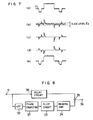
- Figs. 7(a) to 7(e) are a diagram for explaining waveforms produced in the circuit of Fig. 6;
- Fig. 8 is a block diagram showing another embodiment of the present invention;
- Fig. 9 is a graph showing the frequency characteristics of the apparatus according to the present invention;
- Fig. 10 is a diagram showing an example of an edge portion component emphasis circuit for a large signal;
- Fig. 11 is a block diagram showing the essential parts of a recording system which makes the apparatus according to the invention more effective;
- Fig. 12 is a diagram showing still another embodiment of the present invention; and
- Fig. 13 is a diagram for explaining waveforms produced in the circuit of Fig. 12.
- In Fig. 3, a color television signal is applied through a color video
signal input terminal 1 to a low-pass filter 2 where a luminance signal Ey up to 3 MHz is separated. A nonlinear emphasis circuit 3 is for providing an instantaneous nonlinear emphasis characteristic whereby the frequency characteristics remain flat for a large signal input while the intermediate and high frequency components are emphasized for a small signal. The nonlinear emphasis circuit 3 is designed, for instance, as shown in Fig. 4A. A variable resistor R3 is made up of a diode limiter. If constants are determined in such a manner that the relation
dark clip circuit 5 wherein an FM frequency (Sync. tip frequency) corresponding to the sync. signal position is set so that the tip of the hairs of the luminance signal emphasized is clipped into a range recordable by VTR. The resulting signal is FM modulated at anFM modulator 6, thereby eliminating the unrequired spectrum. For instance, such a signal is applied through a 1-MHz high-pass filter 7 to amixer 12 where it is added to low frequency-converted carrier chrominance signal Ec and recorded in a magnetic recording medium by avideo head 13. In theFM modulator 6, the frequency deviation is set at the width of 1 MHz of, say, 3.4 to 4.4 MHz, the white clip frequency is set at, say, 5.3 MHz, and the dark clip frequency is set at, say, 2.9 MHz. In the case of azimuth recording without any guardband between the tracks TA and TB as shown in Fig. 2, reproduction of one track is overlapped somewhat on adjacent tracks, thus causing crosstalk. In order to overcome this problem, it is common practice to set the azimuth loss at -20 to -30 dB while arranging horizontal sync. signals side by side in adjacent tracks TA and TB. Thus the components not required to be demodulated are zero in beat in view of the fact that there is some correlation between the signal involved and the difference in FM carrier frequencies of the tracks. For instance, the track width W involved is 58 µm and the azimuth angle θ is 6 degrees. When the tape speed is decreased and the track width W narrowed, the azimuth loss is reduced as mentioned above. As a result, even though the horizontal sync. signals are in juxtaposition between tracks, crosstalks pose a problem where the signal correlation is lost, while in a format with horizontal sync. signals not in juxtaposition, crosstalks are aggravated. In such a case, the carrier frequency of theFM modulator 6 is differentiated by
pass filter 8 where a carrier chrominance signal of subcarrier frequency fs=3.58 MHz andband width 1 of 0.5 MHz is separated. This carrier chrominance signal is frequency-converted at a frequency converter 9 by a continuous wave 10 of frequency fs=fc. A carrier chrominance signal Ec converted into a low subcarrier frequency fc is separated at a low-pass filter 11 and added to the luminance FM signal at amixer 12. The resulting signal is recorded in the magnetic recording medium in a spectrum as shown in Fig. 5A. In the case of the azimuth guardbandless recording as shown in Fig. 2, the subcarrier frequency fc of the low-frequency converted carrier chrominance signal for recording is generally selected at several hundred KHz, and therefore the resulting long wavelength for recording reduces the azimuth loss. Thus the phase of the carrier of the continuous wave 10 for track TA is advanced by 90 degrees for each line (one horizontal period). As a result, as shown in Fig. 5B, the spectrum of the low frequency converted carrier chrominance signal has intervals of fH on both sides of

- For the purpose of reproduction, the reproduction signal from the video head B is separated into a luminance FM signal and a low frequency-converted carrier chrominance signal by a high-
pass filter 14 and a low-pass filter 22 respectively. The amplitude variation of the separated luminance FM signal is removed by alimiter circuit 15, and the resulting signal is demodulated into a reproduction luminance signal by anFM demodulator 16 and a low-pass filter 17. The intermediate and high frequency characteristics of this signal are dampened by ade-emphasis circuit 18 having a function reverse to that of the emphasis circuit 4 for recording, thus reducing the demodulation noises for reproduction. The output of thede-emphasis circuit 18 is inverted or inversely converted by a nonlinearde-emphasis circuit 19 in such a manner that the intermediate and high frequency is dampened in response to a small signal input while flat characteristics are maintained in response to a large signal input. Noises of the resulting signal are further reduced by a noise supress ornoise canceller circuit 20 and added to the reproduction carrier chrominance signal mentioned later at amixer 28, thus producing a color video signal at an output terminal 29. The low frequency-converted carrier chrominance signal separated as above, on the other hand, is frequency converted at afrequency converter 23 by thecontinuous wave 30 of frequency fc+fs, and is produced in the form of the original carrier chrominance signal through a band-pass filter 24. Crosstalks between adjacent tracks which occur in this signal are removed by a C-type comb filter 25 including asubtractor 27 for subtracting the output of a one-horizontalperiod delay circuit 26 and a signal not so delayed one from the other, thereby producing a reproduction carrier chrominance signal. Further, at the time of reproduction, the low frequency-converted carrier chrominance signal Ec changes with time. This change is compensated for by afrequency converter 23 through APC or AFC in which thecontinuous wave 30 of frequency fc+fs is also simultaneously subjected to-the same change with time. - The block diagram of Fig. 3 is that of a simple VTR called VHS in trade name. Now, assume that the tape speed is reduced to 1/3 with the track width of 19 µm or the recording of an even higher density with a shorter wavelength and narrower track is effected. With the decrease in track width, the signal-to-noise ratio is reduced in proportion to the root thereof. At the same time, the azimuth loss is reduced and the crosstalks from adjacent tracks increase. In order to solve this problem, the amount of emphasis X of the nonlinear emphasis circuit 3 may be increased so that the demodulation noises for reproduction are reduced more for a smaller signal, thus securing a similar signal-to-noise ratio. In this way, a proper S/N is secured and small crosstalks are dampened as far as a small-amplitude signal at the flat portion and edge portion is concerned. Nevertheless, the signal-to-noise ratio is not improved for a large signal, i.e., the large-amplitude portion of the edge portion since the frequency characteristics are flat. Nor are crosstalks dampened. Therefore, the picture quality becomes noisier and more unsightly with the increase in amplitude of the edge component signal. Although the crosstalk from adjacent tracks can be reduced visually for the parts having a line correlationship, the edge portion where the line correlation is easily lost becomes more unsightly with the increase in crosstalks even when the FM interleave is used. Also, in the noise supress or
noise canceller circuit 20, the components of flat portions or edge portions with small amplitude can be reduced in noise, but the noises in the flat portions or edge portions of a large amplitude cannot be reduced, so that the edge portion becomes very unsightly as compared with the flat portions due to noises and crosstalks. As described above, even though a method for recording with short wavelength and narrow track has been developed in which the signal-to-noise ratio and crosstalks are reduced for the flat portions or edge portions of small amplitude, any method or system by which the signal-to-noise ratio is improved and crosstalks are reduced for the edge portion of large amplitude (such as rise and fall of the luminance signal) has not yet been developed. - In view of this fact, the present invention obviates the above-mentioned shortcomings and provides a method for signal processing by which the noise and crosstalks of the edge portion are reduced and thus the signal-to-noise ratio is improved.
- The present invention will be described in detail below with reference to the drawings. A basic block diagram of the present invention is shown in Fig. 6 and a diagram for explaining the operation thereof is shown in Fig. 7.
- A reproduction video signal having noises and crosstalks components as shown in Fig. 7(a) is applied to a reproduction video
signal input terminal 31. The signal from the reproduction videosignal input terminal 31 is applied to a high-pass filter 32 where intermediate and high frequency components forming the edge component of the video signal as shown in Fig. 7(b) is extracted. The corner frequency of the high-pass filter 32 is about 0.5 to 1.5 MHz depending on the noises or crosstalks involved. The intermediate and high frequency components thus obtained are sliced to slice level Eg with a predetermined threshold value by use of a nonlinear element within aslice circuit 33, thus producing a signal containing crosstalks and noises of only the edge portion and the intermediate and high frequency components of the edge component as shown in Fig. 7(c). The phase of this signal (c) is inverted by areverse amplifier 34, thus producing a signal of Fig. 7(d). These signals of Figs. 7(d) and 7(a) are added to each other at an appropriate ratio by amixer 35, thus producing a signal of Fig. 7(e) at the reproduction videosignal output terminal 36, which signal has the same amount of noises as the signal of Fig. 7(a) in the flat portion and has not any noises or crosstalks in the edge portion. - As seen from Fig. 6 or 7, those components of the flat portion and the edge portion (rise and fall of the luminance signal and intermediate and high frequency components) which are within a predetermined threshold level Es are ignored, so that only those signal components which have exceeded the level Es and noises and crosstalks are picked up. The original signal is subtracted proportionately to a predetermined amount corresponding to such components picked up, thus eliminating the noises and crosstalks. At the same time, the signal components associated with the edge component are slightly eliminated, thus somewhat "slackening" the rise and fall. This portion, however, is very small as compared with the whole signal due to small noises or crosstalks, and therefore the signal is not deteriorated so seriously, thus posing no problem for the simple-type VTR at all. Reference characters (a), (b), (c), (d) and (e) in Fig. 6 correspond to (a) to (e) in Fig. 7 respectively.
- The block diagram of Fig. 8 shows a circuit for further improving the meritorious effect of the present invention. Reference numerals in the drawing similar to those in Fig. 6 denote like component parts as in Fig. 6. In Fig. 8, a
phase corrector 37 is provided in a high frequency- processing system for phase correction which is required in view of the fact that the group delay characteristics of the high-pass filter 32 change and the phase advances with the increase in frequency. Further, adelay circuit 38 is inserted in the original reproduction video signal system so that the two signals added in themixer 35 coincide with each other in timing, thus placing the two signals in phase in a predetermined frequency range such as from 0.5 to 3 MHz. As a result, noises and crosstalks between adjacent tracks are dampened over a wide range. - In Fig. 6 or 8, if the
reverse amplifier 34 is absent, themixer 35 may of course be able to have the same effect by addition of a subtractor. Instead, a circuit for correcting the frequency characteristics may be inserted at an appropriate point. - The frequency characteristics of the circuits of Figs. 6 and 8 will be explained below. When the input signal is small and the output of the high-
pass filter 32 is smaller than the slice levet Es, no output is produced at (c), but the same input signal is produced at the output (e) of this circuit, thus providing a flat frequency characteristic as shown in Fig. 9 with reference to the application of a small signal. When the input signal is large, by contrast, theslice circuit 33 fully conducts, so that the characteristics of the high-pass filter 32 and the input signal. characteristics are subtracted by a predetermined value. As a result, the intermediate and high frequency ranges are dampened, thus leading to the de-emphasis characteristics as shown in Fig. 9 in connection with the application of a large signal. In similar fashion, with application of a middle signal input, the amount of de-emphasis is reduced below that of a large signal. If it is unacceptable that the rise and fall of the edge component of large amplitude somewhat slackens, it is desirable to insert a circuit as shown in Fig. 10 in the main signal route of Fig. 6 or 8. Specifically, the emitter resistor Rs and the collector resistor R4 of a transistor make up an amplifier. A capacitor C3 and a resistor R6 high in value as compared with the resistor R5 are used for differentiation. Diodes D1 and D2 are connected to both sides of the resistors Re as shown betweenconnection point 39 and mass potential thus making up a limiter. With the application of a large signal to the input terminal, diodes D, and D2 conduct so that the intermediate and high frequency characteristics are emphasized by the impedance due to the resistor R5, capacitor C3 and the conduction resistances of the diodes D, and D2. As a result, a signal without any slackening in waveform is produced from the circuits shown in the block diagrams of Figs. 6 and 8 showing the basic configurations of the present invention. - The reproduction
video input terminal 31, on the other hand, is impressed with a signal not de-emphasized which is an output of the low-pass filter 17. This signal is the one emphasized at the time of recording, and therefore the high-pass filter 32 may be comparatively simply constructed, thus facilitating phase correction. - As explained above, the intermediate and high frequency components corresponding to the edge component are separated, and a signal sliced at a low level is added to the reproduction video signal at opposite polarities, with the result that the noises and crosstalks contained in the edge portion are removed by a very simple construction on the one hand and the signal-to-noise ratio at the edge is improved on the other hand. Further, by adding the intermediate and high frequency components and the noises to each other at opposite polarities as shown in Fig. 7(e), the frequency characteristics are deteriorated to some degree but this causes no problem for the simple-type recorder at all. If it causes a problem, such a problem is easily solved by a configuration such as shown in Fig. 10.
- In order to further improve the performance of signal reproduction, a circuit is provided for emphasizing the intermediate and high frequency range in advance at the time of recording. In this way, the reproduction frequency characteristics are restored thus eliminating the noises and crosstalks from the edge portion.
- The diagram of Fig. 11 shows an example of such a method. In this diagram, a video signal input terminal 40 is impressed with a video output signal from the emphasis circuit 4 in Fig. 3. The intermediate and high frequency component of this video signal is produced from the high-
pass filter 41, and added to the input video signal at amixer 43 through aslice circuit 42 including a nonlinear element, thus producing a signal at theoutput terminal 44. This signal is recorded after being frequency- modulated by thefrequency modulator 6. Without the edge component emphasis circuit as shown in Fig. 11, it is of course possible to design an ordinary emphasis circuit 4 in such a manner as to provide the emphasis characteristics thereof including the characteristics of such an additional emphasis circuit. - The operation of the circuit of Fig. 11 will be explained below. In the case where the output of the high-
pass filter 41 is lower than the slice level, theoutput 44 is proportional to the level Ei of the input video signal, while the sum of the input video signal level Ei and the y characteristic of the nonlinear element is produced at the output terminal when the output of the high-pass filter 41 is higher than the slice level Es. In other words, this configuration is such that the intermediate and high frequency components are emphasized. In this way, the reverse converters of Figs. 6 and 8 restore the original frequency characteristics, thus eliminating the noises and crosstalks at the edge portion. - The circuit of Fig. 11 is similar to the noise supress circuit of a noise reduction circuit used with a conventional reproduction system but is different in that the circuit of Fig. 11 has no low-pass filter of the same corner frequency as the high-
pass fitter 41 in themixer 43 and the video signal input terminal 40. For this reason, the intermediate and high frequency characteristics of a large signal can be emphasized. - The output of the low-
pass filter 17 of Fig. 3 is not necessarily used as an input signal in Figs. 6 and 8. Alternatively, in the case where the signal from thede-emphasis circuit 18 or the nonlinearde-emphasis circuit 19 is used as an input signal, the output of the nonlinear emphasis circuit 3 or the low-pass filter 2 may be used as an input signal in Fig. 11. - In the case of Fig. 6 or 8, the signal-to-noise ratio of the flat portion of the video signal is not improved and therefore a conventional
noise reduction circuit 20 is employed usually in a stage after the circuit according to the present invention. A simple configuration integrating such a function while maintaining the same performance is shown in Fig. 12, and waveforms produced in such a circuit are shown in Fig. 13. - With reference to Fig. 12, the
input terminal 45 is impressed with a reproduction video signal, i.e., the output of the nonlinearde-emphasis circuit 19 of Fig. 3, the waveform of which is shown in Fig. 7(a). This signal is applied to a frequency characteristics-correctingcircuit 46 and a high-pass filter 50. The frequency characteristics-correctingcircuit 46 is for correcting the frequency characteristics which are deteriorated by the function of noise reduction at the flat portion. The high-pass filter 50 produces an intermediate and high frequency component of the edge portion (Fig. 7(b)), which is amplified by anamplifier 51. The resulting signal is amplitude-limited at a low level by alimiter 52, thus separating noises of the flat portion, part of the edge of large amplitude and components of the edge of small amplitude as shown in Fig. 13(a). This signal is applied in proper amount to asubtractor 48 through theamplitude regulator 54. In view of the fact that the reproduction video signal from the frequency characteristics-correctingcircuit 46 is applied to thesubtractor 48 through thesubtractor 47, the signal of Fig. 13(a) is subtracted from the signal of Fig. 7(a), thus reducing the noises of the flat portion. In other words, theparts pass filter 50, on the other hand, is applied to theslice circuit 53 described with reference to Fig. 8, where the noise component of the flat portion is eliminated, so that as shown in Fig. 7(c), the noises and crosstalks included in the edge component and intermediate and high frequency components of the edge portion are picked up. This signal is applied in appropriate amount to thesubtractor 47, thus eliminating the noises and crosstalks of the edge portion. As a result, a signal shown in Fig. 13(b) in which the noises and crosstalks at both the edge portion and flat portion are dampened is produced at theoutput terminal 49. Theoutput terminal 49 is connected to themixer 28 in Fig. 3. In this case, thenoise reduction circuit 20 is of course done without. According to the method of Fig. 12, it is possible to reduce noises and crosstalks by a simple circuit configuration by dual use of the high-pass filter 50. Further, assuming that thecomponent parts means 48, the frequency characteristics are reverse to those shown in Fig. 9. Specifically, the amount of de-emphasis is increased with the decrease in magnitude of the signal and therefore, in the circuit of Fig. 12 where theparts circuit 46, however, the frequency characteristics for all signals from small to large become flat, so that sharp edge portion is obtained on the one hand and the noises and crosstalks of the edge portion and flat portion are eliminated. As mentioned above, noises higher than several hundreds KHz are dampened while at the same time eliminating those crosstalks higher than several hundred KHz out of the crosstalks of 0 to 2.4 MHz, i.e., the difference between the maximum FM modulated frequency and the minimum FM modulated frequency (5.3-2.9=2.4 MHz). In view of the fact that the demodulated crosstalk component, due to triangular noises, has a large amplitude in proportion to the difference in FM carrier frequency between tracks, the crosstalks of 0 to several hundred KHz do not cause any problem. If it presents a problem, however, such crosstalks can be reduced visually, i.e., in appearance in the range having a line correlation by use of the FM interleaving technique. - It will thus be understood that crosstalks and noises of the edge portion are eliminated sufficiently thus improving the signal-to-noise ratio thereof. In this way, it is possible to make recording at high density with short wave- length and narrow tracks.
- An application of the present invention is included in VHS (trade name) 6-hour VTR with the track width of 19 µm and relative speed of 5.8 m/s. By using the method of the present invention, the recording and reproduction with narrower tracks at lower relative speed is made possible on the one hand and a compact apparatus is realized on the other hand. Further, the crosstalks and the signal-to-noise ratio of the flat portion and edge portion are substantially equalized, thus producing a stable picture with a high signal-to-noise ratio. Although the foregoing description deals with an NTSC color television signal, the present invention is of course also applicable to the color television signal of PAL or SECAM system in which the luminance signal is FM modulated for recording and reproduction.
Claims (5)
Applications Claiming Priority (2)
| Application Number | Priority Date | Filing Date | Title |
|---|---|---|---|
| JP2398179A JPS55117712A (en) | 1979-02-28 | 1979-02-28 | Noise reduction circuit of video signal recording and reproducing device |
| JP23981/79 | 1979-02-28 |
Publications (3)
| Publication Number | Publication Date |
|---|---|
| EP0015499A1 EP0015499A1 (en) | 1980-09-17 |
| EP0015499B1 true EP0015499B1 (en) | 1983-04-27 |
| EP0015499B2 EP0015499B2 (en) | 1986-05-28 |
Family
ID=12125730
Family Applications (1)
| Application Number | Title | Priority Date | Filing Date |
|---|---|---|---|
| EP80100975A Expired EP0015499B2 (en) | 1979-02-28 | 1980-02-27 | Video signal recording and reproducing apparatus |
Country Status (4)
| Country | Link |
|---|---|
| US (1) | US4597021A (en) |
| EP (1) | EP0015499B2 (en) |
| JP (1) | JPS55117712A (en) |
| DE (1) | DE3062857D1 (en) |
Families Citing this family (46)
| Publication number | Priority date | Publication date | Assignee | Title |
|---|---|---|---|---|
| JPS57180823U (en) * | 1981-05-07 | 1982-11-16 | ||
| US4563704A (en) * | 1981-06-19 | 1986-01-07 | Victor Company Of Japan, Ltd. | Noise reduction circuit for a video signal |
| EP0077010B1 (en) * | 1981-10-14 | 1986-03-12 | TELEFUNKEN Fernseh und Rundfunk GmbH | Circuit for reducing the rise-time of the flanks of a video signal, in particular for a video recorder |
| JPS5897114A (en) * | 1981-12-07 | 1983-06-09 | Hitachi Ltd | Nonlinear emphasis circuit |
| JPS5956204A (en) * | 1982-09-25 | 1984-03-31 | Victor Co Of Japan Ltd | Magnetic recording and reproducing device |
| US4611231A (en) * | 1983-05-31 | 1986-09-09 | Matsushita Electric Industrial Co., Ltd. | Signal processing apparatus for a video signal |
| US4538178A (en) * | 1983-06-24 | 1985-08-27 | Rca Corporation | Digital signal peaking apparatus with controllable peaking level |
| JPS6051388A (en) * | 1983-08-31 | 1985-03-22 | Sony Corp | Secondary beat cancelling circuit |
| JPS6093682A (en) * | 1983-10-25 | 1985-05-25 | Sony Corp | Digital non-linear pre-emphasis circuit |
| JPS6155253U (en) * | 1984-09-18 | 1986-04-14 | ||
| DE3521991A1 (en) * | 1985-06-20 | 1987-01-02 | Thomson Brandt Gmbh | CIRCUIT TO IMPROVE PLAYBACK SHARPNESS IN A VIDEO RECORDER |
| JPS61142894A (en) * | 1985-10-18 | 1986-06-30 | Hitachi Ltd | Chrominance signal recording and reproducing circuit |
| JPH0799562B2 (en) * | 1986-08-02 | 1995-10-25 | ソニー株式会社 | Video signal recorder |
| JP2570717B2 (en) * | 1987-02-03 | 1997-01-16 | ソニー株式会社 | Comb filter |
| US4882618A (en) * | 1987-04-15 | 1989-11-21 | Kabushiki Kaisha Toshiba | FM signal demodulator for video signal reproducing apparatus |
| US4864404A (en) * | 1987-05-22 | 1989-09-05 | Victor Company Of Japan, Ltd. | Noise reduction circuit of a video signal |
| US4860105A (en) * | 1987-05-22 | 1989-08-22 | Victor Company Of Japan, Ltd. | Noise Reducing circuit of a video signal |
| JPH01150059U (en) * | 1988-03-31 | 1989-10-17 | ||
| DE3915454A1 (en) * | 1988-05-12 | 1989-12-07 | Mitsubishi Electric Corp | INVERSION PHENOMEN CANCELING |
| US4908581A (en) * | 1988-07-21 | 1990-03-13 | Matsushita Electric Industrial Co., Ltd. | Frequency demodulator having circuit cancelling undesired signal components |
| US5126846A (en) * | 1988-08-08 | 1992-06-30 | Kabushiki Kaisha Toshiba | Non-linear amplifier and non-linear emphasis/deemphasis circuit using the same |
| JPH02103776A (en) * | 1988-10-11 | 1990-04-16 | Canon Inc | Signal processor |
| JPH0810533B2 (en) * | 1988-10-20 | 1996-01-31 | 日本ビクター株式会社 | Magnetic playback device |
| JPH02192074A (en) * | 1989-01-19 | 1990-07-27 | Sanyo Electric Co Ltd | High range noise reduction circuit |
| KR920010512B1 (en) * | 1989-01-27 | 1992-11-30 | 가부시끼가이샤 히다찌세이사꾸쇼 | Image pick-up device |
| JPH02301277A (en) * | 1989-05-15 | 1990-12-13 | Toshiba Corp | Recording processing circuit for video signal |
| US5144434A (en) * | 1989-07-13 | 1992-09-01 | Canon Kabushiki Kaisha | Video signal processing device using look-up table |
| JP3074697B2 (en) * | 1990-04-24 | 2000-08-07 | ソニー株式会社 | Video signal FM recording device |
| US5822490A (en) * | 1990-05-31 | 1998-10-13 | Samsung Electronics Co., Ltd. | Apparatus and method for color-under chroma channel encoded with a high frequency luminance signal |
| US5500739A (en) * | 1990-05-31 | 1996-03-19 | Samsung Electronics Co., Ltd. | Frequency-multiplexing FM luma signal with color and 2nd under signals having overlapping frequency spectra |
| US6134373A (en) * | 1990-08-17 | 2000-10-17 | Samsung Electronics Co., Ltd. | System for recording and reproducing a wide bandwidth video signal via a narrow bandwidth medium |
| US6104863A (en) | 1990-08-17 | 2000-08-15 | Samsung Electronics Co., Ltd. | Video signal encoded with additional detail information |
| US6246827B1 (en) | 1990-08-17 | 2001-06-12 | Samsung Electronics Co., Ltd. | Deemphasis and subsequent reemphasis of high-energy reversed-spectrum components of a folded video signal |
| US5673355A (en) * | 1990-08-17 | 1997-09-30 | Samsung Electronics Co., Ltd. | Deemphasis & Subsequent reemphasis of high-energy reversed-spectrum components of a folded video signal |
| US5596418A (en) * | 1990-08-17 | 1997-01-21 | Samsung Electronics Co., Ltd. | Deemphasis and subsequent reemphasis of high-energy reversed-spectrum components of a folded video signal |
| KR930010928B1 (en) * | 1990-08-17 | 1993-11-17 | 삼성전자 주식회사 | Video signal recording system enabling limited bandwidth recording and playback |
| KR940001422B1 (en) * | 1990-10-26 | 1994-02-23 | 삼성전자 주식회사 | Deemphasis & reemphasis of vidio signal at high frequency |
| KR940001423B1 (en) * | 1990-10-26 | 1994-02-23 | 삼성전자 주식회사 | Deemphasis & reemphasis of high frequency vidio signal at recording control signal |
| KR0166745B1 (en) * | 1995-07-10 | 1999-03-20 | 김광호 | Color signal processor removing leakage components |
| US7042518B1 (en) * | 2002-04-29 | 2006-05-09 | National Semiconductor Corporation | Digitally controlled variable frequency HF emphasis circuit for use in video displays |
| JP3968644B2 (en) * | 2002-05-24 | 2007-08-29 | ソニー株式会社 | Signal processing apparatus and method, recording medium, and program |
| KR100688511B1 (en) * | 2004-12-20 | 2007-03-02 | 삼성전자주식회사 | Digital processing apparatus and method for estimating subcarrier included in video signal |
| KR100780937B1 (en) * | 2004-12-20 | 2007-12-03 | 삼성전자주식회사 | Digital processing apparatus and method for estimating horizontal sync included in video signal |
| DE102007030067B4 (en) * | 2007-06-29 | 2011-08-25 | Siemens Medical Instruments Pte. Ltd. | Hearing aid with passive, input-level-dependent noise reduction and method |
| US11677938B2 (en) * | 2008-04-30 | 2023-06-13 | Arris Enterprises Llc | Method to reduce contour artifacts on recursive temporal filters |
| US9721588B2 (en) * | 2015-12-28 | 2017-08-01 | Avago Technologies General Ip (Singapore) Pte. Ltd. | Magnetic recording system including differentiated write current emphasis signal generator circuit |
Family Cites Families (23)
| Publication number | Priority date | Publication date | Assignee | Title |
|---|---|---|---|---|
| US3333055A (en) * | 1963-06-01 | 1967-07-25 | Fernseh Gmbh | Apparatus for increasing the signal-to-noise ratio of a television signal |
| DE1437488A1 (en) * | 1964-03-18 | 1969-04-30 | Hans Wellhausen | Method and circuit for suppressing interference voltages of small amplitudes in audio and video-frequency signals |
| US3288930A (en) * | 1964-11-12 | 1966-11-29 | Winston Res Corp | Wide-band signal-translating channel |
| US3443029A (en) * | 1966-06-15 | 1969-05-06 | Philco Ford Corp | Noise suppression circuit |
| US3571526A (en) * | 1968-09-30 | 1971-03-16 | Ampex | Method and apparatus of eliminating pilot signal interference in fm magnetic tape recorder systems |
| DE1908247B2 (en) * | 1969-02-19 | 1971-03-04 | Fernseh Gmbh, 6100 Darmstadt | CIRCUIT ARRANGEMENT FOR REDUCING HIGHER FREQUENCY INTERFERENCES (NOISE) IN BROADBAND ELECTRICAL SIGNALS, IN PARTICULAR TELEVISION SIGNALS |
| US3715477A (en) * | 1971-03-11 | 1973-02-06 | Rca Corp | Video signal noise-limiting apparatus |
| US3700803A (en) * | 1971-03-15 | 1972-10-24 | Gte Sylvania Inc | Self-tracking noise suppressing circuit |
| JPS5427868Y2 (en) * | 1972-08-31 | 1979-09-08 | ||
| JPS4987314A (en) * | 1972-12-23 | 1974-08-21 | ||
| US3893168A (en) * | 1974-03-07 | 1975-07-01 | Rca Corp | Technique for minimizing interference in video recorder reproducer systems |
| US3984865A (en) * | 1975-03-26 | 1976-10-05 | Rca Corporation | Transient suppression in television video systems |
| US4009334A (en) * | 1976-03-17 | 1977-02-22 | Eastman Kodak Company | Video noise reduction circuit |
| US4052740A (en) * | 1976-03-19 | 1977-10-04 | Ampex Corporation | Moire interference reducing circuit for fm video recorders |
| JPS5327010A (en) * | 1976-08-25 | 1978-03-13 | Sony Corp | Signal tran smitter |
| US4110784A (en) * | 1976-08-30 | 1978-08-29 | Rca Corporation | Noise reduction apparatus |
| JPS5350919A (en) * | 1976-10-20 | 1978-05-09 | Sony Corp | Video signal recorder unit |
| US4200889A (en) * | 1976-12-27 | 1980-04-29 | Basf Aktiengesellschaft | Complementary pre-emphasis and de-emphasis circuits for a video signal transfer channel |
| JPS5953602B2 (en) * | 1977-03-07 | 1984-12-26 | 松下電器産業株式会社 | Noise removal device |
| JPS5412714A (en) * | 1977-06-29 | 1979-01-30 | Matsushita Electric Ind Co Ltd | Recorder-reproducer |
| US4142211A (en) * | 1977-11-23 | 1979-02-27 | Microtime, Inc. | Bidimensional noise reduction system for television |
| US4254436A (en) * | 1978-08-18 | 1981-03-03 | Rca Corporation | Noise cancellation circuit |
| US4249202A (en) * | 1979-05-09 | 1981-02-03 | Ampex Corporation | Circuit for frequency selective coring of a video signal |
-
1979
- 1979-02-28 JP JP2398179A patent/JPS55117712A/en active Granted
-
1980
- 1980-02-27 DE DE8080100975T patent/DE3062857D1/en not_active Expired
- 1980-02-27 EP EP80100975A patent/EP0015499B2/en not_active Expired
-
1985
- 1985-01-22 US US06/693,233 patent/US4597021A/en not_active Expired - Lifetime
Also Published As
| Publication number | Publication date |
|---|---|
| EP0015499B2 (en) | 1986-05-28 |
| DE3062857D1 (en) | 1983-06-01 |
| JPS6226233B2 (en) | 1987-06-08 |
| JPS55117712A (en) | 1980-09-10 |
| EP0015499A1 (en) | 1980-09-17 |
| US4597021A (en) | 1986-06-24 |
Similar Documents
| Publication | Publication Date | Title |
|---|---|---|
| EP0015499B1 (en) | Video signal recording and reproducing apparatus | |
| US5359426A (en) | Reproducing a bandwidth expanded chroma signal with reduced noise and reduced flicker | |
| CA1201804A (en) | Chroma signal recording and reproducing circuit | |
| JPH039679B2 (en) | ||
| JPH0253997B2 (en) | ||
| JPS6151346B2 (en) | ||
| JPS6222318B2 (en) | ||
| EP0133048B1 (en) | Noise reducing system for video signal | |
| US4571613A (en) | Noise reduction circuit for a video signal using a feedback type comb filter and an equalizer circuit | |
| GB2137846A (en) | Noise reducing system for a video signal | |
| CA1119286A (en) | Noise and cross-talk elimination in recording and reproducing video signals | |
| US4356506A (en) | Automatic chrominance control circuit for a color video tape recorder | |
| EP0177235B1 (en) | Apparatus for recording audio and video signals | |
| EP0076047B1 (en) | Color video signal recording and reproducing apparatus | |
| EP0196097A2 (en) | Method of field/frame conversion in magnetic picture recording and reproducing | |
| US5153741A (en) | Crosstalk cancelling circuit for playback chrominance signal of VTR | |
| JPS5836876B2 (en) | SECAM color video signal recording and playback system | |
| JP2600254B2 (en) | Television composite video signal generator | |
| JPS62183057A (en) | Magnetic recording device | |
| JPH0545116B2 (en) | ||
| JPS63500066A (en) | Method and apparatus for reducing noise when playing video signals | |
| JPS61237592A (en) | Frequency division multiple signal processing circuit | |
| JPS6016157B2 (en) | SECAM color television signal recording and playback system | |
| JPS6347031B2 (en) | ||
| JPH0139274B2 (en) |
Legal Events
| Date | Code | Title | Description |
|---|---|---|---|
| PUAI | Public reference made under article 153(3) epc to a published international application that has entered the european phase |
Free format text: ORIGINAL CODE: 0009012 |
|
| AK | Designated contracting states |
Designated state(s): DE FR GB |
|
| 17P | Request for examination filed |
Effective date: 19810218 |
|
| GRAA | (expected) grant |
Free format text: ORIGINAL CODE: 0009210 |
|
| AK | Designated contracting states |
Designated state(s): DE FR GB |
|
| ET | Fr: translation filed | ||
| REF | Corresponds to: |
Ref document number: 3062857 Country of ref document: DE Date of ref document: 19830601 |
|
| PLBI | Opposition filed |
Free format text: ORIGINAL CODE: 0009260 |
|
| 26 | Opposition filed |
Opponent name: GRUNDIG E.M.V. ELEKTRO-MECHANISCHE VERSUCHSANSTALT Effective date: 19840126 |
|
| PUAH | Patent maintained in amended form |
Free format text: ORIGINAL CODE: 0009272 |
|
| STAA | Information on the status of an ep patent application or granted ep patent |
Free format text: STATUS: PATENT MAINTAINED AS AMENDED |
|
| 27A | Patent maintained in amended form |
Effective date: 19860528 |
|
| AK | Designated contracting states |
Kind code of ref document: B2 Designated state(s): DE FR GB |
|
| ET3 | Fr: translation filed ** decision concerning opposition | ||
| REG | Reference to a national code |
Ref country code: GB Ref legal event code: 746 Effective date: 19950224 |
|
| REG | Reference to a national code |
Ref country code: FR Ref legal event code: D6 |
|
| PGFP | Annual fee paid to national office [announced via postgrant information from national office to epo] |
Ref country code: FR Payment date: 19960125 Year of fee payment: 17 |
|
| PGFP | Annual fee paid to national office [announced via postgrant information from national office to epo] |
Ref country code: GB Payment date: 19960219 Year of fee payment: 17 |
|
| PGFP | Annual fee paid to national office [announced via postgrant information from national office to epo] |
Ref country code: DE Payment date: 19960227 Year of fee payment: 17 |
|
| PG25 | Lapsed in a contracting state [announced via postgrant information from national office to epo] |
Ref country code: GB Effective date: 19970227 |
|
| GBPC | Gb: european patent ceased through non-payment of renewal fee |
Effective date: 19970227 |
|
| PG25 | Lapsed in a contracting state [announced via postgrant information from national office to epo] |
Ref country code: FR Effective date: 19971030 |
|
| PG25 | Lapsed in a contracting state [announced via postgrant information from national office to epo] |
Ref country code: DE Effective date: 19971101 |
|
| REG | Reference to a national code |
Ref country code: FR Ref legal event code: ST |