EP0014525A1 - Forward viewing aid for vehicle drivers - Google Patents
Forward viewing aid for vehicle drivers Download PDFInfo
- Publication number
- EP0014525A1 EP0014525A1 EP80300116A EP80300116A EP0014525A1 EP 0014525 A1 EP0014525 A1 EP 0014525A1 EP 80300116 A EP80300116 A EP 80300116A EP 80300116 A EP80300116 A EP 80300116A EP 0014525 A1 EP0014525 A1 EP 0014525A1
- Authority
- EP
- European Patent Office
- Prior art keywords
- vehicle
- reflecting
- aid according
- mirror
- edge
- Prior art date
- Legal status (The legal status is an assumption and is not a legal conclusion. Google has not performed a legal analysis and makes no representation as to the accuracy of the status listed.)
- Withdrawn
Links
Images

Classifications
-
- B—PERFORMING OPERATIONS; TRANSPORTING
- B60—VEHICLES IN GENERAL
- B60R—VEHICLES, VEHICLE FITTINGS, OR VEHICLE PARTS, NOT OTHERWISE PROVIDED FOR
- B60R1/00—Optical viewing arrangements; Real-time viewing arrangements for drivers or passengers using optical image capturing systems, e.g. cameras or video systems specially adapted for use in or on vehicles
- B60R1/10—Front-view mirror arrangements; Periscope arrangements, i.e. optical devices using combinations of mirrors, lenses, prisms or the like ; Other mirror arrangements giving a view from above or under the vehicle
Definitions
- This invention relates to a forward viewing aid for vehicle drivers.
- Vehicle driver viewing aids in the form of mirrors which give a rearward view to the vehicle driver and these mirrors take various forms.
- the mirrors may be mounted within the vehicle or externally on the forward wings or the doors.
- Such mirrors are also known which are mounted on extensions or which are in the form of periscopes to enable the driver to see around trailers or caravans.
- An object of the invention is to provide a forward viewing aid for vehicle drivers which enables a vehicle driver to have a wider field of vision in the forward direction than is possible from the driving position when unaided.
- a forward viewing aid for vehicle drivers comprises two reflecting elements, means for mounting the reflecting elements in juxtaposition relative to one another such that an image ahead of the vehicle received by one reflecting element is reflected from such element to the other reflecting element and the image can be viewed directly by the driver as a reflection from said other reflecting element.
- the planes of the reflecting elements are arranged at an acute angle in the range 14-20 0 to each other, and said one reflecting element receiving the image has a convex reflecting surface.
- the radius of said one reflecting element is in the range 1500-4000 mm and said other reflecting element for viewing the image has a flat reflecting surface.
- a mounting bracket for vehicles comprises an upper part to which a device to be mounted is attachable, the upper part having a surface arranged to engage a portion of the vehicle adjacent an edge of said portion, a lower part carried on the upper part and arranged to locate around said edge to lie opposite said surface and adjustment means interconnecting the upper and lower parts for effecting relative movement of the parts to clamp the parts on said portion of the vehicle, the arrangement being such that the upper and lower parts are clampable around the edge of a bonnet member of the vehicle when the bonnet is raised and cannot be released when the bonnet is lowered.
- a forward viewing aid for vehicle drivers comprising mirrors is illustrated.
- the aid in this case includes a mirror assembly 10, a mounting stem 11 and a mounting bracket 12 for mounting the assembly on a vehicle (not shown).
- the mirror assembly 10 includes two mirrors 13 and 14 of which one 13 is termed the forward facing mirror and it is the mirror 13 which receives an image from ahead of the vehicle to be viewed by the driver.
- the other mirror 14 is termed the rearward facing mirror which reflects the image on the forward facing mirror 13 to the driver.
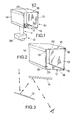
- the mirrors 13 and 14 are arranged in juxtaposition and in fixed overlapping relationship to one another and, to enable the driver to see past obstructions to his normal line of vision, the mirrors have their planes inclined to one another at an angle of 10-20 0 , as more clearly seen in Fig. 3.
- the forward facing mirror 13 has a reflecting surface of convex shape having a focal length in the range 1550-4000 mm typically 2150 mm.
- the provision of a convex mirror widens the field of view of the assembly.
- the rearward facing mirror 14 has a flat reflecting surface.
- Each of the mirrors 13 and 14 is of generally rectangular shape and the mirrors are preferably formed of glass with a reflecting surface applied to one side. Alternatively the reflecting surfaces may be obtained by other means such as prisms or polished metal.
- the mirrors 1-3 and 14 are mounted between upper and lower mounting members 16 and 17 which are each of generally U-shape.
- the assembly 10 is generally in the shape of an open-ended box, the limbs 18 of the U-shaped members 16 and 17 being secured to the rear of the mirrors 13 and 14 and the bases 19 and 20 of the members 16 and 17 forming the upper and lower sides of the box.
- a hole 21 is formed through which a bolt 23 of the mounting stem 11 is located.
- the head 24 of the bolt engages the upper side of the base 19 and the bolt extends downwardly so that its lower end is located in the bracket 12.
- a compression spring 26 which is engaged at its lower end by a collar 27 having a flat upper surface and a hemi-spherical lower surface.
- a tube 28 Around the bolt 23 below the collar is a tube 28, the upper circular end of which engages the hemi-spherical surface of the collar.
- the arrangement of the stem 11 enables the mirror assembly to be adjustable relative to the stem about the axis of the bolt 23 and about the axis of the hemi-spherical surface to enable the driver to make adjustments to give the desired field of view.
- the lower end of the bolt 23 engages through a hole 29 in a member 30 of the bracket 12 and is secured in place by a nut 31.
- the bracket member 30 is of generally U-shape and is directed generally horizontally so that the top limb 30A of the U contains the hole 29 for the bolt 23 and a further two holes 32, the holes 29 and 32 being unthreaded and the holes 32 being countersunk Lo receive the heads of clamping bolts 33.
- a further bolt 33' is located in the member 30 and has a rubber head 33A to engage a vehicle body portion 35A by rotation in a threaded hole in the member 30.
- the bracket 12 includes a further oppositely-facing U-shaped member 34, one limb 34A of which is located between the limbs of the member 30 and contains threaded holes through which the bolts 33 engage.
- the bolts 33 also engage through threaded holes in the other limb 30B of the member 30 which lies below the limb 34A of member 34.
- the mounting bracket 12 provides clamping surfaces defined by the lower surface of limb 30B of member 30 and the upper surface of limb 34B of the member 34. By rotation of the bolts 33 these two surfaces are moved towards and away from each other to clamp onto a part 35 of the vehicle body. In use it is intended that the bracket 12 be clamped onto the side edge of a vehicle bonnet 35.
- Vehicle bonnets generally present a side edge which lies against a wing portion 35A of the vehicle and a gutter for water is defined at said edge for running off water.
- the bracket 12 is fitted to the side edge of the bonnet by raising the bonnet so that the side edge of part 35 is unobstructed by the wing 35A, the limb 34B of the member 34 is inserted under the edge and the limb 30B of member 30 lies over the edge.
- the bolts 33, 33' are tightened the upper and lower surfaces of limbs 34B and 30B respectively grip the side edge and the bonnet surfaces adjacent the edge to fix the bracket in position.
- the bridging portion of the member 34 is able to pass between the gap existing between the edge of the bonnet 35 and the wing 35 A so that once the bonnet is closed and locked it is not possible to release the bracket from the vehicle.
- the mirrors 13,14 may be so angled to the vertical that the line of vision of the device is maintained in a substantially horizontal direction.
- the mirror 13 and/or mirror 14 may be adjustable in angle to cater for different bonnet inclinations.
- a refracting prism may be fitted between the mirrors over one end of the assembly to deflect the image reflected by the mirrors up or down to enable the desired forward image to reach the user.
- the mounting bracket may be covered with a cover 36 (as seen in Fig. 1) after fitting to the vehicle to enhance the appearance of the device.
- bracket 12 may be used to mount devices other than the described mirror assembly onto vehicles.
- the bracket may be used for mounting a radio aerial, a luggage rack to be fixed to the boot lid, or other kinds of driver's mirror.
- the mirror assembly described may be usable as a conventional rear view mirror by locating a further mirror in back to back relationship with one of the mirrors 13 and 14 and, in use, re-adjusting the position of the mirror assembly to meet with the different requirements of rear view mirrors.
- one of the mirrors 13 and 14 may be formed with reflective surfaces on both sides, for the same purpose.
- FIG. 5 shows another form of the invention.
- mirrors 113 and 114 are provided having the same function and the same relationship as the mirrors 13 and 14 of the previous embodiment.
- the mirrors 113 and 114 are held in the desired relationship by arms 40 and 41 movable relative to one another about a vertical axis by means of a pivot 42 and each mirror being movable about a horizontal axis relative to its associated arm by means of pivots 43 and 44.
- the arms 40 and 41 are mounted on a bracket 45 having an upstanding stem 46, and the bracket 45 is fixed to the vehicle in conventional manner or by means of the bracket of the previous embodiment.
- the light path P from an image F to the driver G is also shown in Fig. 5.
- a further mirror 47 is fixed to the mirror 113 to enable the device to be used in the manner of a driver's rear view mirror in a similar manner to that described for the previous embodiment.
- the mirrors 113 and 114 will be moved together by pivoting the arms 40 and 41 so that the mirrors 113 and 114 are in face to face arrangement and the mirror 47 positioned for the new viewing requirement.
Abstract
A forward viewing aid for vehicle drivers is intended particularly for drivers driving on the other side of the road to that for which their vehicles are equipped.
It consists of a pair of mirrors (13, 14) arranged side by side so that the driver extends his field of view to see around obstructions ahead of the vehicle. One mirror (13) is a forward-facing mirror and reflections from this mirror are transmitted to the other mirror (14) which faces the driver.
In one arrangement the mirrors are in a box-like assembly supported adjustably on a stem (11) which is in turn mounted on a bracket (12) clamped to the vehicle.
To provide for the bracket (12)to be readily detached from the vehicle, there is a clamping arrangement by which the bracket (12) is only removable on lifting the vehicle bonnet.
Description
- This invention relates to a forward viewing aid for vehicle drivers.
- Vehicle driver viewing aids in the form of mirrors are known which give a rearward view to the vehicle driver and these mirrors take various forms. For example, the mirrors may be mounted within the vehicle or externally on the forward wings or the doors. Such mirrors are also known which are mounted on extensions or which are in the form of periscopes to enable the driver to see around trailers or caravans.
- It has also been proposed to provide a mirror located within the vehicle whereby a forward view can be achieved but this mirror has not proved popular due to the need to locate it away from the driver's normal line of vision. However, a need for forward-viewing aids for vehicle drivers exists especially when a vehicle travels on the opposite side of the road to that for which it is equipped, for example, a vehicle equipped with a right-hand side driving position which is driven on the right hand side of the road. In such a case the driver must move his vehicle towards the crown of the road in order to see past a vehicle in front and to determine whether the road is clear for overtaking. This procedure is hazardous, as is a similar procedure when it is necessary for the driver to pull out to see past a large preceding vehicle when in the usual driving position.
- An object of the invention is to provide a forward viewing aid for vehicle drivers which enables a vehicle driver to have a wider field of vision in the forward direction than is possible from the driving position when unaided.
- According to one aspect of the invention a forward viewing aid for vehicle drivers comprises two reflecting elements, means for mounting the reflecting elements in juxtaposition relative to one another such that an image ahead of the vehicle received by one reflecting element is reflected from such element to the other reflecting element and the image can be viewed directly by the driver as a reflection from said other reflecting element.
- Preferably the planes of the reflecting elements are arranged at an acute angle in the range 14-200 to each other, and said one reflecting element receiving the image has a convex reflecting surface.
- Conveniently the radius of said one reflecting element is in the range 1500-4000 mm and said other reflecting element for viewing the image has a flat reflecting surface.
- According to another aspect of the invention a mounting bracket for vehicles comprises an upper part to which a device to be mounted is attachable, the upper part having a surface arranged to engage a portion of the vehicle adjacent an edge of said portion, a lower part carried on the upper part and arranged to locate around said edge to lie opposite said surface and adjustment means interconnecting the upper and lower parts for effecting relative movement of the parts to clamp the parts on said portion of the vehicle, the arrangement being such that the upper and lower parts are clampable around the edge of a bonnet member of the vehicle when the bonnet is raised and cannot be released when the bonnet is lowered.
- Further features of the invention will appear from the following description of embodiments of the invention given by way of example only and with reference to the drawings in which:
- Fig. 1 is a perspective view of one embodiment of vehicle forward viewing aid,
- Fig. 2 is a perspective view of part of the system of Fig. 1 showing the arrangement of mirrors and the mounting means for the mirrors to an enlarged scale,
- Fig. 3 is a diagrammatic view of the light path through the mirror system of Fig. 2,
- Fig. 4 is an elevation of the mounting arrangement of the embodiment of Figs. 1-3, and
- Fig. 5 is a perspective view of a further embodiment of vehicle mirror system.
- Referring to the drawings and firstly to Figs. 1-4, a forward viewing aid for vehicle drivers comprising mirrors is illustrated. The aid in this case includes a
mirror assembly 10, amounting stem 11 and amounting bracket 12 for mounting the assembly on a vehicle (not shown). - The
mirror assembly 10 includes twomirrors mirror 13 which receives an image from ahead of the vehicle to be viewed by the driver. Theother mirror 14 is termed the rearward facing mirror which reflects the image on the forward facingmirror 13 to the driver. Themirrors - The forward facing
mirror 13 has a reflecting surface of convex shape having a focal length in the range 1550-4000 mm typically 2150 mm. The provision of a convex mirror widens the field of view of the assembly. The rearward facingmirror 14 has a flat reflecting surface. - Each of the
mirrors - The mirrors 1-3 and 14 are mounted between upper and
lower mounting members assembly 10 is generally in the shape of an open-ended box, thelimbs 18 of the U-shapedmembers mirrors bases members - In the
base 19 of the member 16 ahole 21 is formed through which abolt 23 of themounting stem 11 is located. Thehead 24 of the bolt engages the upper side of thebase 19 and the bolt extends downwardly so that its lower end is located in thebracket 12. - Around the upper end of the
bolt 23 and below thebase 19 is acompression spring 26 which is engaged at its lower end by acollar 27 having a flat upper surface and a hemi-spherical lower surface. Around thebolt 23 below the collar is atube 28, the upper circular end of which engages the hemi-spherical surface of the collar. - The arrangement of the
stem 11 enables the mirror assembly to be adjustable relative to the stem about the axis of thebolt 23 and about the axis of the hemi-spherical surface to enable the driver to make adjustments to give the desired field of view. - The lower end of the
bolt 23 engages through ahole 29 in amember 30 of thebracket 12 and is secured in place by anut 31. Thebracket member 30 is of generally U-shape and is directed generally horizontally so that thetop limb 30A of the U contains thehole 29 for thebolt 23 and a further twoholes 32, theholes holes 32 being countersunk Lo receive the heads of clampingbolts 33. A further bolt 33' is located in themember 30 and has arubber head 33A to engage avehicle body portion 35A by rotation in a threaded hole in themember 30. - The
bracket 12 includes a further oppositely-facing U-shapedmember 34, onelimb 34A of which is located between the limbs of themember 30 and contains threaded holes through which thebolts 33 engage. Thebolts 33 also engage through threaded holes in theother limb 30B of themember 30 which lies below thelimb 34A ofmember 34. - It will be seen that the
mounting bracket 12 provides clamping surfaces defined by the lower surface oflimb 30B ofmember 30 and the upper surface oflimb 34B of themember 34. By rotation of thebolts 33 these two surfaces are moved towards and away from each other to clamp onto apart 35 of the vehicle body. In use it is intended that thebracket 12 be clamped onto the side edge of avehicle bonnet 35. Vehicle bonnets generally present a side edge which lies against awing portion 35A of the vehicle and a gutter for water is defined at said edge for running off water. Thebracket 12 is fitted to the side edge of the bonnet by raising the bonnet so that the side edge ofpart 35 is unobstructed by thewing 35A, thelimb 34B of themember 34 is inserted under the edge and thelimb 30B ofmember 30 lies over the edge. As thebolts 33, 33' are tightened the upper and lower surfaces oflimbs member 34 is able to pass between the gap existing between the edge of thebonnet 35 and thewing 35 A so that once the bonnet is closed and locked it is not possible to release the bracket from the vehicle. However, it remains a simple matter for the vehicle driver to release and raise the bonnet and release the bracket. This feature is particularly advantageous when the invention is used on occasional journeys of the vehicle to countries where the vehicle is driven on the opposite side of the road to that for which the vehicle is equipped. - It will be noted that since the side edge of the bonnets of some vehicles slopes downwards in the forwards direction it may be advantageous for the
mirrors mirror 13 and/ormirror 14 may be adjustable in angle to cater for different bonnet inclinations. - In an alternative arrangement a refracting prism may be fitted between the mirrors over one end of the assembly to deflect the image reflected by the mirrors up or down to enable the desired forward image to reach the user.
- The mounting bracket may be covered with a cover 36 (as seen in Fig. 1) after fitting to the vehicle to enhance the appearance of the device.
- It will be appreciated that the
bracket 12 may be used to mount devices other than the described mirror assembly onto vehicles. For example, the bracket may be used for mounting a radio aerial, a luggage rack to be fixed to the boot lid, or other kinds of driver's mirror. - The mirror assembly described may be usable as a conventional rear view mirror by locating a further mirror in back to back relationship with one of the
mirrors mirrors - Referring now to Fig. 5, this shows another form of the invention.
- In this case two
mirrors mirrors mirrors arms 40 and 41 movable relative to one another about a vertical axis by means of a pivot 42 and each mirror being movable about a horizontal axis relative to its associated arm by means ofpivots - The
arms 40 and 41 are mounted on abracket 45 having anupstanding stem 46, and thebracket 45 is fixed to the vehicle in conventional manner or by means of the bracket of the previous embodiment. The light path P from an image F to the driver G is also shown in Fig. 5. - A
further mirror 47 is fixed to themirror 113 to enable the device to be used in the manner of a driver's rear view mirror in a similar manner to that described for the previous embodiment. In such a case themirrors arms 40 and 41 so that themirrors mirror 47 positioned for the new viewing requirement.
Claims (10)
1. A forward viewing aid for vehicle drivers characterised by two reflecting elements (13, 14; 113, 114), mounting means (16, 17; 40, 41, 46) for mounting the reflecting elements in juxtaposition relative to one another such that an image ahead of the vehicle received by one reflecting element is reflected from such element to the other reflecting element and the image can be viewed directly by the driver as a reflection from said other reflecting element.
2. An aid according to claim 1 characterised in that the planes of the reflecting elements (13, 14; 113, 114) are arranged at an acute angle in the range 10-20 to each other.
3. An aid according to claim 1 or 2 characterised in that said one reflecting element (13; 113) receiving the image has a convex reflecting surface.
4. An aid according to claim 3 characterised in that the radius of said one element (l3; 113) is in the range 1500-4000 mm.
5. An aid according to any one of the preceding claims characterised in that said other reflecting element (14; 114) for viewing the image has a flat reflecting surface.
6. An aid according to any one of the preceding claims characterised in that the reflecting elements (13, 14; 113) 114) are generally rectangular and are spaced apart in a direction transverse to the reflecting surfaces of the elements in overlapping relationship.
7. An aid according to any one of the preceding claims characterised in that the mounting means (16, 17; 40, 41, 46) for the reflecting elements (13, 14; 113, 114) interconnects the two reflecting elements to maintain the elements in fixed relationship to one another without obstructing the light path to the driver.
8. An aid according to claim 7 characterised by a stem (23) extending downwardly from the mounting means (16, 17) and having a mounting bracket (12) at its lower end, the mounting bracket including an upper part (30) of which a surface is arranged to engage an upwardly-facing portion (35) of a vehicle adjacent an edge of said portion, and a lower part (34) carried adjustably on the upper part and arranged to engage around said edge and under said upwardly facing portion (35), whereby the upper and lower parts are fixable on the vehicle by adjustment of the upper and lower parts to clamp the bracket on the vehicle.
9. An aid according to claim 8 characterised in that the mounting means (16, 17) is adjustable relative to the mounting bracket (12) to adjust the orientation of the reflecting elements (13, 14) relative to the vehicle driver.
10. A mounting bracket for vehicles comprising an upper part to which a device to be mounted is attachable and a lower part, characterised in that the upper part (30) has a surface arranged to engage a portion (35) of the vehicle adjacent an edge of said portion, the lower part (34) being carried on the upper part and arranged to locate around said edge to lie opposite said surface, and characterised by adjustment means (33) interconnecting the upper and lower parts (30 and 34) for effecting relative movement of the parts to clamp the parts on said portion (35) of the vehicle, the arrangement being such that the upper and lower parts are clampable around the edge of a bonnet member of the vehicle when the bonnet is raised and cannot be released with the bonnet in a lowered position.
Applications Claiming Priority (2)
| Application Number | Priority Date | Filing Date | Title |
|---|---|---|---|
| GB7902583 | 1979-01-24 | ||
| GB7902583 | 1979-01-24 |
Publications (1)
| Publication Number | Publication Date |
|---|---|
| EP0014525A1 true EP0014525A1 (en) | 1980-08-20 |
Family
ID=10502718
Family Applications (1)
| Application Number | Title | Priority Date | Filing Date |
|---|---|---|---|
| EP80300116A Withdrawn EP0014525A1 (en) | 1979-01-24 | 1980-01-14 | Forward viewing aid for vehicle drivers |
Country Status (1)
| Country | Link |
|---|---|
| EP (1) | EP0014525A1 (en) |
Cited By (7)
| Publication number | Priority date | Publication date | Assignee | Title |
|---|---|---|---|---|
| GB2124565A (en) * | 1982-06-07 | 1984-02-22 | Janshort Limited | Vehicle front view device |
| GB2177665A (en) * | 1985-07-20 | 1987-01-28 | Peter Leslie Caplehorn | Front view mirror |
| GB2206855A (en) * | 1987-06-11 | 1989-01-18 | Andre Orssaud | Front view mirror device |
| GB2208633A (en) * | 1987-08-17 | 1989-04-12 | Atisit Pilanun | Front-view and rear-view mirror assembly for vehicles and conveyances |
| GB2215689A (en) * | 1988-03-13 | 1989-09-27 | Graham Leese | Vehicle forward view overtaking mirror |
| US5559640A (en) * | 1995-03-29 | 1996-09-24 | Rockwell International Corporation | Automotive rear view mirror system |
| GB2336576A (en) * | 1998-04-21 | 1999-10-27 | Glyn Edin Michael Tuvnes | Forward view overtaking mirror |
Citations (12)
| Publication number | Priority date | Publication date | Assignee | Title |
|---|---|---|---|---|
| BE535766A (en) * | ||||
| GB254214A (en) * | 1925-06-27 | 1926-07-01 | Denis Fleuriau | Mirror device for forward and back vision for motor and like vehicles |
| FR617959A (en) * | 1926-06-21 | 1927-03-01 | Device enabling the driver of any vehicle to see the side of his vehicle and the road followed at the same time | |
| FR32362E (en) * | 1926-09-04 | 1927-11-28 | Device enabling the driver of any vehicle to see the side of his vehicle and the road followed at the same time | |
| US1666236A (en) * | 1927-01-19 | 1928-04-17 | Sydney W Fuerth | Sight instrument for automobiles |
| US2132026A (en) * | 1936-07-27 | 1938-10-04 | James E Griffith | Forward view mirror for automobiles |
| US2302952A (en) * | 1941-04-14 | 1942-11-24 | John F Pfeifer | Mirror attachment for automobiles |
| CH275669A (en) * | 1949-09-12 | 1951-05-31 | Mathys Robert | Road vehicle. |
| FR56418E (en) * | 1945-04-20 | 1952-09-24 | Safety device for automobiles in overtaking maneuvers | |
| FR1084175A (en) * | 1952-03-18 | 1955-01-17 | Viewfinder for vehicles of all kinds | |
| GB1127233A (en) * | 1965-02-01 | 1968-09-18 | Gerald Jack Galley | An improvement in or relating to mirror apparatus for use on a motor vehicle |
| FR2215337A1 (en) * | 1973-01-29 | 1974-08-23 | Perrier Marcel |
-
1980
- 1980-01-14 EP EP80300116A patent/EP0014525A1/en not_active Withdrawn
Patent Citations (12)
| Publication number | Priority date | Publication date | Assignee | Title |
|---|---|---|---|---|
| BE535766A (en) * | ||||
| GB254214A (en) * | 1925-06-27 | 1926-07-01 | Denis Fleuriau | Mirror device for forward and back vision for motor and like vehicles |
| FR617959A (en) * | 1926-06-21 | 1927-03-01 | Device enabling the driver of any vehicle to see the side of his vehicle and the road followed at the same time | |
| FR32362E (en) * | 1926-09-04 | 1927-11-28 | Device enabling the driver of any vehicle to see the side of his vehicle and the road followed at the same time | |
| US1666236A (en) * | 1927-01-19 | 1928-04-17 | Sydney W Fuerth | Sight instrument for automobiles |
| US2132026A (en) * | 1936-07-27 | 1938-10-04 | James E Griffith | Forward view mirror for automobiles |
| US2302952A (en) * | 1941-04-14 | 1942-11-24 | John F Pfeifer | Mirror attachment for automobiles |
| FR56418E (en) * | 1945-04-20 | 1952-09-24 | Safety device for automobiles in overtaking maneuvers | |
| CH275669A (en) * | 1949-09-12 | 1951-05-31 | Mathys Robert | Road vehicle. |
| FR1084175A (en) * | 1952-03-18 | 1955-01-17 | Viewfinder for vehicles of all kinds | |
| GB1127233A (en) * | 1965-02-01 | 1968-09-18 | Gerald Jack Galley | An improvement in or relating to mirror apparatus for use on a motor vehicle |
| FR2215337A1 (en) * | 1973-01-29 | 1974-08-23 | Perrier Marcel |
Cited By (8)
| Publication number | Priority date | Publication date | Assignee | Title |
|---|---|---|---|---|
| GB2124565A (en) * | 1982-06-07 | 1984-02-22 | Janshort Limited | Vehicle front view device |
| GB2177665A (en) * | 1985-07-20 | 1987-01-28 | Peter Leslie Caplehorn | Front view mirror |
| GB2206855A (en) * | 1987-06-11 | 1989-01-18 | Andre Orssaud | Front view mirror device |
| GB2206855B (en) * | 1987-06-11 | 1991-05-01 | Andre Orssaud | Device for improving visibility in road vehicles |
| GB2208633A (en) * | 1987-08-17 | 1989-04-12 | Atisit Pilanun | Front-view and rear-view mirror assembly for vehicles and conveyances |
| GB2215689A (en) * | 1988-03-13 | 1989-09-27 | Graham Leese | Vehicle forward view overtaking mirror |
| US5559640A (en) * | 1995-03-29 | 1996-09-24 | Rockwell International Corporation | Automotive rear view mirror system |
| GB2336576A (en) * | 1998-04-21 | 1999-10-27 | Glyn Edin Michael Tuvnes | Forward view overtaking mirror |
Similar Documents
| Publication | Publication Date | Title |
|---|---|---|
| US5237458A (en) | Device for adjusting automobile side view mirror | |
| US3826563A (en) | Side view mirror attachment for motor vehicle | |
| US5165081A (en) | Auxiliary clamp-on mirror | |
| US5237459A (en) | Vehicular visual safety device | |
| US6685347B2 (en) | Gobo projector for a vehicle | |
| GB2210835A (en) | Vehicle forward view mirror | |
| US7156532B2 (en) | Blind spot curved mirror | |
| US6120155A (en) | Reflector device and system for viewing the rear seat of a vehicle | |
| US4016653A (en) | Sighting device for a vehicle | |
| EP0014525A1 (en) | Forward viewing aid for vehicle drivers | |
| US4187001A (en) | View expanding apparatus | |
| US1666236A (en) | Sight instrument for automobiles | |
| US4381142A (en) | Rear view mirror attachment | |
| US5122910A (en) | Device for adjusting automobile side view mirror | |
| US6588911B1 (en) | Three-piece interior rear view mirror assembly | |
| US7416205B1 (en) | Hitch mirror assembly | |
| US2132026A (en) | Forward view mirror for automobiles | |
| GB2230750A (en) | Rear view mirrors | |
| US5500773A (en) | Vehicle mirror alignment device | |
| US4435044A (en) | Rear view mirror assembly | |
| US6422706B1 (en) | Apparatus and method for positioning a mirror in a motor vehicle to ensure correct coverage of a critical field of view | |
| US5412511A (en) | Holding device for interior mirrors in vehicles | |
| US4114989A (en) | Overhead roof-mounted rear view mirror | |
| GB2040843A (en) | Rearview mirrors | |
| AU2005229635B2 (en) | Distortion free image capture mirror assembly |
Legal Events
| Date | Code | Title | Description |
|---|---|---|---|
| PUAI | Public reference made under article 153(3) epc to a published international application that has entered the european phase |
Free format text: ORIGINAL CODE: 0009012 |
|
| AK | Designated contracting states |
Designated state(s): DE FR GB IT |
|
| STAA | Information on the status of an ep patent application or granted ep patent |
Free format text: STATUS: THE APPLICATION IS DEEMED TO BE WITHDRAWN |
|
| 18D | Application deemed to be withdrawn |
Effective date: 19810605 |