EP0009108A2 - An improved laser having a nonlinear phase conjugating reflector - Google Patents
An improved laser having a nonlinear phase conjugating reflector Download PDFInfo
- Publication number
- EP0009108A2 EP0009108A2 EP79102854A EP79102854A EP0009108A2 EP 0009108 A2 EP0009108 A2 EP 0009108A2 EP 79102854 A EP79102854 A EP 79102854A EP 79102854 A EP79102854 A EP 79102854A EP 0009108 A2 EP0009108 A2 EP 0009108A2
- Authority
- EP
- European Patent Office
- Prior art keywords
- laser
- wave
- medium
- phase conjugate
- sbs
- Prior art date
- Legal status (The legal status is an assumption and is not a legal conclusion. Google has not performed a legal analysis and makes no representation as to the accuracy of the status listed.)
- Granted
Links
Images
Classifications
-
- G—PHYSICS
- G02—OPTICS
- G02F—OPTICAL DEVICES OR ARRANGEMENTS FOR THE CONTROL OF LIGHT BY MODIFICATION OF THE OPTICAL PROPERTIES OF THE MEDIA OF THE ELEMENTS INVOLVED THEREIN; NON-LINEAR OPTICS; FREQUENCY-CHANGING OF LIGHT; OPTICAL LOGIC ELEMENTS; OPTICAL ANALOGUE/DIGITAL CONVERTERS
- G02F1/00—Devices or arrangements for the control of the intensity, colour, phase, polarisation or direction of light arriving from an independent light source, e.g. switching, gating or modulating; Non-linear optics
- G02F1/35—Non-linear optics
- G02F1/353—Frequency conversion, i.e. wherein a light beam is generated with frequency components different from those of the incident light beams
- G02F1/3536—Four-wave interaction
- G02F1/3538—Four-wave interaction for optical phase conjugation
-
- H—ELECTRICITY
- H01—ELECTRIC ELEMENTS
- H01S—DEVICES USING THE PROCESS OF LIGHT AMPLIFICATION BY STIMULATED EMISSION OF RADIATION [LASER] TO AMPLIFY OR GENERATE LIGHT; DEVICES USING STIMULATED EMISSION OF ELECTROMAGNETIC RADIATION IN WAVE RANGES OTHER THAN OPTICAL
- H01S3/00—Lasers, i.e. devices using stimulated emission of electromagnetic radiation in the infrared, visible or ultraviolet wave range
- H01S3/05—Construction or shape of optical resonators; Accommodation of active medium therein; Shape of active medium
- H01S3/08—Construction or shape of optical resonators or components thereof
-
- H—ELECTRICITY
- H01—ELECTRIC ELEMENTS
- H01S—DEVICES USING THE PROCESS OF LIGHT AMPLIFICATION BY STIMULATED EMISSION OF RADIATION [LASER] TO AMPLIFY OR GENERATE LIGHT; DEVICES USING STIMULATED EMISSION OF ELECTROMAGNETIC RADIATION IN WAVE RANGES OTHER THAN OPTICAL
- H01S3/00—Lasers, i.e. devices using stimulated emission of electromagnetic radiation in the infrared, visible or ultraviolet wave range
- H01S3/10—Controlling the intensity, frequency, phase, polarisation or direction of the emitted radiation, e.g. switching, gating, modulating or demodulating
- H01S3/10076—Controlling the intensity, frequency, phase, polarisation or direction of the emitted radiation, e.g. switching, gating, modulating or demodulating using optical phase conjugation, e.g. phase conjugate reflection
Definitions
- the present invention relates to lasers and, more particularly, to an improved laser which corrects for distortions in the wavefronts of the laser beam.
- a nonlinear phase conjugate reflecting means is employed as one of the reflecting surfaces in a laser resonator.
- a means to control the phase conjugating process namely, an aperture stop, which acts as a reference plane for the.phase conjugation process.
- the aperture stop is chosen or selected to allow only the fundamental mode to exit through it. Since all the light that exists at the aperture is of the fundamental mode, maximum power output is achieved.
- the nonlinear phase conjugate reflecting means corrects for distortions in the wavefronts of the laser beam by reflecting the complex phase conjugate image of the distorted incident optical wavefront.
- the reflected wave encounters the abnormality which initially caused the distortion, because it is the phase conjugate image of the distorted wave, it interacts with the abnormalities to form a plane wave.
- the first embodiment of the invention employs a stimulated Brillouin scattering device, or SBS device, as the nonlinear phase conjugate reflecting means.
- an incident wavefront which is deformed by an abnormality, impinges upon the SDS device and sets up acoustic waves in the SBS medium.
- the acoustic waves are generated by electrostriction, wherein there is an interaction of high intensity electric fields of the laser energy with the SBS medium.
- the electrostriction process periodically modulates the density of the SBS medium, setting up acoustic waves in response to the electric field impulses. The process is extremely fast compared to the distortions caused by . any abnormality, turbulence, lens deformation, or the like.
- the acoustic waves that are set up in the SBS medium conform identically to the incident optical wavefronts, and act as reflecting surfaces for the optical wavefronts which impinge upon these acoustic waves. Therefore, the complex phase conjugate image of the incident optical wavefront is reflected, and when the wave encounters the abnormality which initially caused the deformation, the distorted wave is corrected as it passes the abnormality, and forms a plane wave.
- the second embodiment utilizes the process of four-wave mixing to accomplish the wavefront correction.
- Two pump waves emitted by either two external lasers of identical frequency or one laser and beamsplitting optics, produce coherent optical beams which are incident upon a nonlinear medium from opposite directions.
- a phase hologram is set up in the medium by the interaction of the two pump waves and an aberrated wavefront with the medium.
- the aberrated wavefront incident upon the pumped medium is reflected as a phase conjugate waveform.
- use of an appropriate absorbing or amplifying medium allows for amplitude holograms to be set up in the medium which results in the phase conjugation process.
- the third embodiment utilizes the process of three-wave mixing, commonly known as parametric down-conversion.
- the aberrated wavefronts are incident upon a non- linear medium.
- an external laser emits a pump having twice the frequency component of the aberrated waves which is also made incident upon the medium from the same direction.
- the interaction of the waves and the medium produce the phase conjugate waveform to be transmitted by the nonlinear medium.
- This waveform is then transmitted back along the incident optical path of the initial aberrated wavefront by conventional means.
- the fourth embodiment utilizes the process of photon echoes to produce phase conjugate reflected images.
- This process is similar to that of the SBS process, but the non- linear medium is different.
- an aberrated waveform incident upon the nonlinear medium deforms the medium.
- a laser pulse emitted by an external laser subsequently incident upon this deformed medium is reflected as the complex phase conjugate waveform of the incident . aberrated waveform.
- the process herein is very fast as compared to that of the SBS process. The process takes place within several centimeters of the input surface of the nonlinear system.
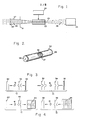
- FIG. 1 of the drawings there is shown an embodiment of an improved laser constructed in accordance with the present invention. It includes an output element 20, a non-linear phase conjugate reflecting means 23, and a lasing medium 22 disposed between the output element 20 and the non-linear reflecting means 23, and situated along an optical axis through the approximate optical centers of these components.
- a support structure (not shown), is provided to position and mount the components of the laser.
- the laser may employ any conventional lasing medium 22. It may employ a crystal, such as ruby, or the like; a gas, such as carbon dioxide, or the like; or a dye, such as Rhodamine 6G, or the like.
- the lasing medium 22 is excited by means of a pump or excitation means 24 of any conventional type, such as Xenon flashlamp, high energy electron beam,. high voltage electric discharge, or the like.
- the output element 20 is partially reflective and partially transmissive with respect to laser energy of the particular frequency emitted by the lasing medium 22.'
- the output element 20 is depicted as a generalized output element.
- An aperture stop 21 is disposed along the optical axis near the output element 20, and allows only the fundamental mode to exit the laser through the partially transmissive output element 20.
- the opening in the aperture stop 21 is sized to allow only the fundamental mode to pass through.
- the energy exiting the laser through the partially transmissive output element 20 is the output laser beam.
- the non- linear phase conjugate reflecting means 23 is selected to be of the type which reflects the complex phase conjugate image of the incident optical wavefront, instead of a conventional plane mirror reflector or the deformable mirror system mentioned above. It is to be understood that the nonlinear phase conjugating reflecting means 23 is to be distinguished from the plane mirror or deformable mirror reflectors, or the like.
- the nonlinear reflecting means 23 refers to a particular type of material which has unique optical properties, In the deformable mirror system the mirror breaks up an incident laser beam into separate beams. The system deals with each separate beam individually and by means of a servo system tries to sum the individual phase contributions of each of the separate beams to get an optimally phased beam on target.
- the nonlinear reflecting means 23 With the nonlinear reflecting means 23 the whole beam is processed simultaneously and almost instantaneously without servo systems or additional mechanical means.
- the nonlinear phase conjugate reflecting means 23 may take on several forms.
- the second reflecting means 23 is a stimulated Brillouin scattering device, hereinafter referred to as an SBS device.
- an SBS device is a thin-walled tube 36 or waveguide, which may be made of glass and filled with a nonlinear medium 37, such as carbon disulfide, or the like.
- the tube 36 may vary in length from several inches to several feet, with its cross- section being on the order of one-eighth inch to several inches in diameter. The guiding property is assured when the index of the medium is higher than that of the waveguide walls.
- Optical windows 38, 39 such as Brewster angle windows, or the like, are affixed to the ends of the tube 36 to allow for transmission of the laser beam.
- the SBS device configuration (tube 36, windows 38, 39 and medium 37) will hereinafter be utilized in representing a generalized nonlinear medium and will be designated as nonlinear device 50, although other media could be used in its place and are referred to in the description.
- the SBS device operates in such a manner as to reflect the complex phase conjugate waveform of the incident waveform.
- Acoustic waves are set up in the nonlinear device 50 through the process of electrostriction.
- the impinging light energy - is reflected from these acoustic waves so as to be the complex phase conjugate waveform of the incident energy.
- the improved laser of FIG. 1 corrects for distortions and associated problems in the laser energy wavefronts caused by imperfections in the output element 20, vibration of the output element 20, aperture stop 21 or nonlinear reflecting means 23, misalignment of the output element 20 or nonlinear reflecting means 23, temperature-varying phenomena due to component heating, aberrations in the lasing medium 22, turbulence in the lasing medium 22, or the like.
- These problems normally lower system efficiency and keep . the system from performing at its diffraction limit (i.e., optimum focusing capability), but are alleviated in the improved laser system of the present invention.
- FIG. 3a there is shown an incident wave 30 impinging upon an abnormality 31 in a conventional prior art laser having only a plane mirror 32.
- the abnormality 31 in the laser medium causes the incident waveshape 30 of FIG. 3a to arrive at the plane mirror 32 with the deformed. shape depicted by waveshape 33.
- the reflected wave 34 (FIG. 3b), when encountering the abnormality 31, is further deformed, as shown by wave 35.
- An incident wavefront 40 is deformed by an abnormality 41 in the optical (FIG. 4a).
- path ⁇ A distorted wavefront 42 impinges upon the SBS device and sets up acoustic waves 44 in the SBS medium.
- the acoustic waves 44 are generated by the process of electrostriction, involving interaction between the high intensity electric fields of the laser energy and the SBS medium.
- the electrostriction process periodically modulates the density of the SBS medium, setting up acoustic waves in response to the electric field impulses.
- This process requires sufficient optical energy, as produced by a laser, due to the existence of a power threshold for the stimulated condition in the SBS device. Furthermore, the acoustic waves are generated in a time on the order of nanoseconds. Thus, the process is extremely fast compared to the distortions caused by the abnormality, turbulence, lens deformation, or the like.
- the acoustic waves 44 that are set up in the SBS medium conform identically to the incident optical wavefronts 42 and act as reflecting surfaces for the optical wavefronts 42 which impinge upon these acoustic waves 44.
- the complex phase conjugate image 45 (FIG. 4b) of the incident optical wavefront (FIG. 3a) is reflected, and when the wave 45 encounters the abnormality . 41 which initially caused the deformation, the distorted wave 45 is corrected as it passes the abnormality 41 and forms a plane wave 46, as depicted in FIG. 4b.
- a frequency shift, or doppler shift, due to the receding acoustic waves in the SBS medium is added to the reflected phase conjugate energy.
- This shift is usually very small being on the order of 1 part in 19 5 , and does not affect performance.
- an incident wavefront of the form E( )e i( ⁇ t-kz+ ⁇ (r)) travelling from left to right along an arbitrary z direction, when reflected from an SBS device is of the form ⁇ E*( )e i(( ⁇ -)t+kz- ⁇ (r)) wherein is a constant indicative of the amount of power reflected compared with that incident (in SBS n ⁇ 1); the wt term is indicative of the incident phase at any point in tine while the ( ⁇ - ⁇ )t term indicates that a frequency shift has occurred; the -kz term indicates a wave travelling to the right at a particular phase velocity and the +kz term indicates the wave is travelling to the left; the ⁇ (r) term is an arbitrary phase aberration term.
- This process is controlled by the aperture stop 21 which is positioned so as to restrict the laser output beam to the fundamental mode.
- the aperture stop 21 provides essentially a reference for the phase conjugation process. Aberrated waveforms to the right of the aperture stop 21, impinge upon it and thus are not reflected. These waveforms thus do not exit the laser.
- the fundamental mode is depicted by the smooth curve 27 with wavefronts 28 to the left of the aperture stop 21.
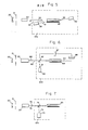
- a second embodiment of the present invention utilizes as the nonlinear reflecting means 23 apparatus which provides four-wave mixing, illustrated in FIG. 5.
- Two pump waves 51, 52, travelling in opposite directions, provided by two external lasers 55, 56 are incident upon a nonlinear device 50 containing a medium such as carbon disulfide.
- a medium such as carbon disulfide.
- pump waves from the two lasers 51, 52 are injected by use of beamsplitters, or the like, into the non- linear medium along a line collinear with the aberrated wave or at a slight angle (- 1"). The latter situation is depicted in FIG. 5.
- a phase hologram is set up in the device 50 by the interaction of the pump waves 51, 52 and an aberrated wave 53 with the device 50.
- an appropriate absorbing or amplifying medium such as ruby or sulfahexa- fluoride CSF 6 1, or the like, results in an amplitude hologram being set up in the medium (phase conjugate waveforms can also be reflected from the amplitude holograms).
- An aberrated wavefront 53 incident upon the pumped device 50 from the laser medium 22 or the like, is reflected as the phase conjugate waveform 54 due to the presence of the second pump wave 52,
- Four-wave mixing does not require the use of two lasers 55, 56. Four-wave mixing is still accomplished if the first pump wave 51 from laser 55 is split.off by a beamsplitter, or the like, and made incident upon the non- linear device 50 from the same direction as was the pump wave 52.
- the mathematical equations are basically the same for this case as it is for the SBS situation.
- the incident wave is of the form E(r)e i( ⁇ t-kz+ ⁇ (r)) and the phase c o n - jugate reflected wave is of the form ⁇ E*( )e i( ⁇ t+kz+ ⁇ (r)) , where n can be greater than 1 (n > 1) due to the presence of the second pump wave 52. This indicates that in four-wave mixing there is a capability of providing gain to the reflected phase-corrected wavefront.
- a third embodiment of the present invention utilizes apparatus providing three-wave mixing, or parametric down conversion, as the nonlinear reflecting means 23. This process is illustrated in FIG. 6.
- An aberrated source wave 60 from the laser medium 22, or the like, is incident upon a nonlinear device 50 containing a medium such as a birefringent crystal, or the like.
- a beamsplitter 62 is disposed in the optical path so as to transmit part of the source wave 60 and reflect into the same optical path, a pump wave 61 from an external laser 65.
- the birefringent crystal has "fast” and “slow” optic axes relative to the phase of the incoming signals,
- the crystal is rotated relative to the phase of both the aberrated wave 60 and pump wave 61 so as to be at the phase matching angle with respect to the two waves 60, 61.
- the pump wave 61 is chosen so as to have a frequency component which is twice that of the source wave 60. Interaction of the pump wave 61, source wave 60, and non- linear device 50, results in an output wave 64 which is proportional to the product of the pump wave 61 and the . complex phase conjugate of the source wave 60. This wave 64 is then reflected by conventional means back along the incident optical path, but in the reverse direction. In order that only the phase conjugate waveform 68 is transmitted back through the lasing medium 22 it is necessary to insert an optical filter 66, such as a multilayer interference filter, or the like, and a polarizer 67 into the optical path. These components 66, 67 filter out the pump wave 61 components and the incident transmitted beam 64, allowing the complex phase conjugate waveform 68 to pass back through the laser cavity.
- an optical filter 66 such as a multilayer interference filter, or the like
- a source wave 60 of the form E s e iwt and a pump wave 61 of the form E p e 2i ⁇ t being incident upon a nonlinear medium 63 results in a transmitted wave of the form ⁇ E p E s *e i ⁇ t , where n ⁇ 1 depending upon the strength of the pump wave 61 and E s * represents the complex conjugate of the incident wave E .
- a fourth embodiment of the present invention utilizes a photon echo device as the nonlinear reflecting means 23 and is illustrated in FIG. 7.
- the photon echo device is substantially the same as the SBS device as depicted in FIG. 2, but with a different nonlinear medium.
- the photon echo embodiment is not limited to the configuration of FIG. 7.
- the photon echo embodiment may also employ the mixing process utilizing two external lasers as shown in FIG. 5.
- Typical media include SF 6 , SiF 4 , BC1 3 , DH 3 F, and I 2 vapor, or the like.
- the nonlinear medium is housed in a tube or waveguide such as glass, or the like, as in the.SBS embodiment and positioned to receive the light energy from the lasing medium 22 of FIG. 1.
- Endcaps are affixed to the ends of the tube as in FIG. 2, both of which may be transmissive or one of which may be totally reflecting, depending upon the configuration used. If both endcaps are transmissive and one external laser is used, then conventional means, such as mirrors may be employed to direct the conjugated beam back through the laser cavity. If both endcaps are transmissive and two lasers are used as in FIG. 5, then the laser emitting pulses to the left (such as laser 56 in FIG. 5, for example) automatically provides a conjugated beam travelling in the required direction; namely to the left with reference to the drawings. If one laser is used, and a totally reflecting mirror is positioned at the correct end of the tube enclosing the medium; namely the right hand end with reference to FIG. 7, then the conjugated beam is reflected in the correct direction (to the left).
- An aberrated light pulse 70 impinging upon the photon echo medium deforms the medium.
- a laser pulse 72 is reflected into the optical path by a beamsplitter 74, or the like, which subsequently impinges upon the deformed medium.
- This pulse 72 is reflected from the medium as the phase conjugate 75 of the aberrated waveform.
- This phase conjugate waveform 75 is corrected as it travels back through the lasing medium 22 to produce a corrected wavefront at the opposite end of the laser.
- the interacting waves are all present at the same time in the medium.
- the aberrated wave to be conjugated and the pump wave, or waves, may also be applied at separate times, and the conjugate wave may be radiated with some delay in the backward or forward direction. This permits storage of pulses, if desired, as well as phase correction by conjugation.
- the photon echo device employed in the present invention is known in the art and is described in a paper by C. V. Heer and P. F. McManamon, "Wavefront Correction with Photon Echos", Optics Communications, Vol. 23, No. 1, Oct. 1977; Yariv, Quantum Electronics, 2d Edition, 1975, ⁇ 15.3 and in a paper submitted for publication in Optics Letters by A. Yariv and J. AuYeung, Transient Four-Wave Mixing and Real Time Holography in a Two-Level Atomic System.
Abstract
Description
- The present invention relates to lasers and, more particularly, to an improved laser which corrects for distortions in the wavefronts of the laser beam.
- In an ideal laser resonator, with no aberrations in the lasing medium or distortions created by the reflecting means, only the fundamental resonating mode would be present. Since all the energy is contained in the single fundamental mode, no power would be lost, and optimum performance would be achieved.
- However, there are problems associated with any laser device. Such problems include vibration of the reflecting surfaces, misalignment of the reflecting surfaces, heating of the reflecting surfaces thus causing warping, aberrations in the lasing medium, and turbulence in the lasing medium. These undesirable conditions result in lower system efficiency, and keep the system from performing at its diffraction limit, i.e., optimum focusing capability.
- In accordance with the invention, a nonlinear phase conjugate reflecting means is employed as one of the reflecting surfaces in a laser resonator. Additionally, there is provided a means to control the phase conjugating process, namely, an aperture stop, which acts as a reference plane for the.phase conjugation process. The aperture stop is chosen or selected to allow only the fundamental mode to exit through it. Since all the light that exists at the aperture is of the fundamental mode, maximum power output is achieved.
- The nonlinear phase conjugate reflecting means corrects for distortions in the wavefronts of the laser beam by reflecting the complex phase conjugate image of the distorted incident optical wavefront. When the reflected wave encounters the abnormality which initially caused the distortion, because it is the phase conjugate image of the distorted wave, it interacts with the abnormalities to form a plane wave.
- In accordance with the present invention, four different embodiments of a nonlinear phase conjugate reflection means are disclosed. The first embodiment of the invention employs a stimulated Brillouin scattering device, or SBS device, as the nonlinear phase conjugate reflecting means.
- In the stimulated Brillouin scattering (SBS) embodiment, an incident wavefront, which is deformed by an abnormality, impinges upon the SDS device and sets up acoustic waves in the SBS medium. The acoustic waves are generated by electrostriction, wherein there is an interaction of high intensity electric fields of the laser energy with the SBS medium. The electrostriction process periodically modulates the density of the SBS medium, setting up acoustic waves in response to the electric field impulses. The process is extremely fast compared to the distortions caused by . any abnormality, turbulence, lens deformation, or the like. The acoustic waves that are set up in the SBS medium conform identically to the incident optical wavefronts, and act as reflecting surfaces for the optical wavefronts which impinge upon these acoustic waves. Therefore, the complex phase conjugate image of the incident optical wavefront is reflected, and when the wave encounters the abnormality which initially caused the deformation, the distorted wave is corrected as it passes the abnormality, and forms a plane wave.
- The second embodiment utilizes the process of four-wave mixing to accomplish the wavefront correction. Two pump waves, emitted by either two external lasers of identical frequency or one laser and beamsplitting optics, produce coherent optical beams which are incident upon a nonlinear medium from opposite directions. A phase hologram is set up in the medium by the interaction of the two pump waves and an aberrated wavefront with the medium. The aberrated wavefront incident upon the pumped medium is reflected as a phase conjugate waveform. Alternatively, use of an appropriate absorbing or amplifying medium allows for amplitude holograms to be set up in the medium which results in the phase conjugation process.
- The third embodiment utilizes the process of three-wave mixing, commonly known as parametric down-conversion. Herein, the aberrated wavefronts are incident upon a non- linear medium. Additionally, an external laser emits a pump having twice the frequency component of the aberrated waves which is also made incident upon the medium from the same direction. The interaction of the waves and the medium produce the phase conjugate waveform to be transmitted by the nonlinear medium. This waveform is then transmitted back along the incident optical path of the initial aberrated wavefront by conventional means.
- The fourth embodiment utilizes the process of photon echoes to produce phase conjugate reflected images. This process is similar to that of the SBS process, but the non- linear medium is different. In the photon echo process, an aberrated waveform incident upon the nonlinear medium deforms the medium. A laser pulse emitted by an external laser subsequently incident upon this deformed medium is reflected as the complex phase conjugate waveform of the incident . aberrated waveform. The process herein is very fast as compared to that of the SBS process. The process takes place within several centimeters of the input surface of the nonlinear system.
- The invention, including its various objects, features and advantages, may be more readily understood with reference to the following detailed description of several embodiments, taken in conjunction with the accompanying drawings, wherein like reference numerals designate like structural elements, and in which:
- FIG. 1 is a diagram of an embodiment of an improved laser constructed in accordance with the present invention;
- FIG. 2 shows an SBS device;
- FIGS. 3a and 3b show waveforms typical of plane mirror reflecting surfaces;
- FIGS. 4a and 4b show waveforms indicative of phase conjugate reflecting means, and stimulated Brillouin scattering (SBS) in particular;
- FIG. 5 shows a laser system implementing the four-wave mixing process;
- FIG. 6 shows a laser system implementing the three-wave mixing process; and
- FIG. 7 shows a laser system implementing the photon echo process.
- Referring now to FIG. 1 of the drawings, there is shown an embodiment of an improved laser constructed in accordance with the present invention. It includes an
output element 20, a non-linear phase conjugate reflectingmeans 23, and alasing medium 22 disposed between theoutput element 20 and thenon-linear reflecting means 23, and situated along an optical axis through the approximate optical centers of these components. A support structure (not shown), is provided to position and mount the components of the laser. - The laser may employ any
conventional lasing medium 22. It may employ a crystal, such as ruby, or the like; a gas, such as carbon dioxide, or the like; or a dye, such as Rhodamine 6G, or the like. The lasingmedium 22 is excited by means of a pump or excitation means 24 of any conventional type, such as Xenon flashlamp, high energy electron beam,. high voltage electric discharge, or the like. - The
output element 20 is partially reflective and partially transmissive with respect to laser energy of the particular frequency emitted by the lasingmedium 22.' Theoutput element 20 is depicted as a generalized output element. Clearly, there are alternative ways of providing output from a laser device which are known to those skilled in the art and we do not wish to be limited to theoutput element 20 herein described. Anaperture stop 21 is disposed along the optical axis near theoutput element 20, and allows only the fundamental mode to exit the laser through the partiallytransmissive output element 20. The opening in theaperture stop 21 is sized to allow only the fundamental mode to pass through. The energy exiting the laser through the partiallytransmissive output element 20 is the output laser beam. - In accordance with the present invention, the non- linear phase
conjugate reflecting means 23 is selected to be of the type which reflects the complex phase conjugate image of the incident optical wavefront, instead of a conventional plane mirror reflector or the deformable mirror system mentioned above. It is to be understood that the nonlinear phase conjugating reflectingmeans 23 is to be distinguished from the plane mirror or deformable mirror reflectors, or the like. The nonlinear reflecting means 23 refers to a particular type of material which has unique optical properties, In the deformable mirror system the mirror breaks up an incident laser beam into separate beams. The system deals with each separate beam individually and by means of a servo system tries to sum the individual phase contributions of each of the separate beams to get an optimally phased beam on target. With the nonlinear reflecting means 23 the whole beam is processed simultaneously and almost instantaneously without servo systems or additional mechanical means. The nonlinear phase conjugate reflecting means 23 may take on several forms. In the embodiment of the improved laser shown in FIG. 1, the second reflecting means 23 is a stimulated Brillouin scattering device, hereinafter referred to as an SBS device. - Although all the properties of the SBS device are not known at the present time, the properties utilized in the present invention are well known, and are discussed in numerous patents and publications. These include, for reference, U.S. Patent 4,005,935, "Method and Apparatus for Providing a Phase Compensated Optical Beam", Wang, (Feb. 1, 1977); "Connection Between Wave Fronts of the Reflected and Excited Light in Stimulated Mandel' Shatm-Brillouin Scattering", Zeldovich et al, ZhETF Pis. Red. 15 No. 3, 160-164 (5 Feb. 1972); and "Cancellation of Phase Distortion in the Amplifying Medium with a Brillouin Mirror", Nosach et al, ZhETF Pis. Red. 16 No. 11, 617-621 (5 Dec. 1972).
- Referring to FIG. 2, generally speaking, an SBS device is a thin-
walled tube 36 or waveguide, which may be made of glass and filled with anonlinear medium 37, such as carbon disulfide, or the like. Thetube 36 may vary in length from several inches to several feet, with its cross- section being on the order of one-eighth inch to several inches in diameter. The guiding property is assured when the index of the medium is higher than that of the waveguide walls.Optical windows tube 36 to allow for transmission of the laser beam. - The SBS device configuration (
tube 36,windows nonlinear device 50, although other media could be used in its place and are referred to in the description. - The SBS device operates in such a manner as to reflect the complex phase conjugate waveform of the incident waveform. Acoustic waves are set up in the
nonlinear device 50 through the process of electrostriction. The impinging light energy - is reflected from these acoustic waves so as to be the complex phase conjugate waveform of the incident energy. - In operation, the improved laser of FIG. 1 corrects for distortions and associated problems in the laser energy wavefronts caused by imperfections in the
output element 20, vibration of theoutput element 20,aperture stop 21 or nonlinear reflecting means 23, misalignment of theoutput element 20 or nonlinear reflecting means 23, temperature-varying phenomena due to component heating, aberrations in thelasing medium 22, turbulence in thelasing medium 22, or the like. These problems normally lower system efficiency and keep . the system from performing at its diffraction limit (i.e., optimum focusing capability), but are alleviated in the improved laser system of the present invention. - Referring to FIG. 3a, there is shown an
incident wave 30 impinging upon anabnormality 31 in a conventional prior art laser having only aplane mirror 32. Theabnormality 31 in the laser medium causes theincident waveshape 30 of FIG. 3a to arrive at theplane mirror 32 with the deformed. shape depicted bywaveshape 33. The reflected wave 34 (FIG. 3b), when encountering theabnormality 31, is further deformed, as shown bywave 35. - Referring now to FIG. 4, the improvement provided by the laser of the present invention is shown. An
incident wavefront 40 is deformed by anabnormality 41 in the optical (FIG. 4a). path< A distortedwavefront 42 impinges upon the SBS device and sets upacoustic waves 44 in the SBS medium. Theacoustic waves 44 are generated by the process of electrostriction, involving interaction between the high intensity electric fields of the laser energy and the SBS medium. The electrostriction process periodically modulates the density of the SBS medium, setting up acoustic waves in response to the electric field impulses. - This process requires sufficient optical energy, as produced by a laser, due to the existence of a power threshold for the stimulated condition in the SBS device. Furthermore, the acoustic waves are generated in a time on the order of nanoseconds. Thus, the process is extremely fast compared to the distortions caused by the abnormality, turbulence, lens deformation, or the like. Within the SBS device, the
acoustic waves 44 that are set up in the SBS medium conform identically to the incidentoptical wavefronts 42 and act as reflecting surfaces for theoptical wavefronts 42 which impinge upon theseacoustic waves 44. - Therefore, the complex phase conjugate image 45 (FIG. 4b) of the incident optical wavefront (FIG. 3a) is reflected, and when the
wave 45 encounters the abnormality . 41 which initially caused the deformation, the distortedwave 45 is corrected as it passes theabnormality 41 and forms aplane wave 46, as depicted in FIG. 4b. - Additionally, a frequency shift, or doppler shift, due to the receding acoustic waves in the SBS medium is added to the reflected phase conjugate energy. This shift is usually very small being on the order of 1 part in 195, and does not affect performance.
- In mathematical terms, an incident wavefront of the form E()ei(ωt-kz+φ(r)) travelling from left to right along an arbitrary z direction, when reflected from an SBS device is of the form ηE*(
 )ei((ω-)t+kz-φ(r)) wherein is a constant indicative of the amount of power reflected compared with that incident (in SBS n < 1); the wt term is indicative of the incident phase at any point in tine while the (ω-δ)t term indicates that a frequency shift has occurred; the -kz term indicates a wave travelling to the right at a particular phase velocity and the +kz term indicates the wave is travelling to the left; the φ(r) term is an arbitrary phase aberration term.
- Referring again to FIG. 1 distorted
wavefronts 26 and higher order modes, represented bywavy lines 26, impinge upon and are reflected by the nonlinear reflecting means 23 (which in this embodiment is the SBS device). Complex conjugate waveforms are reflected towards theoutput element 20. - However, this process is controlled so that a useful, coherent output beam is obtained. Left unrestricted and uncontrolled, use of the SBS device would continually reflect aberrated waveforms back and forth through the system.
- This process is controlled by the
aperture stop 21 which is positioned so as to restrict the laser output beam to the fundamental mode. Theaperture stop 21 provides essentially a reference for the phase conjugation process. Aberrated waveforms to the right of theaperture stop 21, impinge upon it and thus are not reflected. These waveforms thus do not exit the laser. The fundamental mode is depicted by thesmooth curve 27 withwavefronts 28 to the left of theaperture stop 21. - A second embodiment of the present invention utilizes as the nonlinear reflecting means 23 apparatus which provides four-wave mixing, illustrated in FIG. 5. Two pump waves 51, 52, travelling in opposite directions, provided by two
external lasers nonlinear device 50 containing a medium such as carbon disulfide. To increase the interaction length, the area in which phase conjugation takes place, pump waves from the twolasers - A phase hologram is set up in the
device 50 by the interaction of the pump waves 51, 52 and anaberrated wave 53 with thedevice 50. Alternatively, use of an appropriate absorbing or amplifying medium, such as ruby or sulfahexa- fluoride CSF61, or the like, results in an amplitude hologram being set up in the medium (phase conjugate waveforms can also be reflected from the amplitude holograms). Anaberrated wavefront 53 incident upon the pumpeddevice 50 from thelaser medium 22 or the like, is reflected as thephase conjugate waveform 54 due to the presence of thesecond pump wave 52, - Four-wave mixing does not require the use of two
lasers first pump wave 51 fromlaser 55 is split.off by a beamsplitter, or the like, and made incident upon the non-linear device 50 from the same direction as was thepump wave 52. - The mathematical equations are basically the same for this case as it is for the SBS situation. The incident wave is of the form E(r)e i(ωt-kz+φ(r)) and the phase con- jugate reflected wave is of the form ηE*()ei(ωt+kz+φ(r)), where n can be greater than 1 (n > 1) due to the presence of the

second pump wave 52. This indicates that in four-wave mixing there is a capability of providing gain to the reflected phase-corrected wavefront. - This process is discussed in detail in a number of articles and papers, including "Amplified Reflection, Phase Conjugation, and Oscillation in Degenerate Four-Wave Mixing", Yariv, Opt. Lett., Vol. 1, pg, 16, July 1977, and "Generation of Time Reversed Wave Fronts by Nonlinear Refraction", R. W. Hellwarth, J. Opt. Soc. Am., Vol. 67, No.l, Jan. 1977.
- A third embodiment of the present invention utilizes apparatus providing three-wave mixing, or parametric down conversion, as the
nonlinear reflecting means 23. This process is illustrated in FIG. 6. Anaberrated source wave 60, from thelaser medium 22, or the like, is incident upon anonlinear device 50 containing a medium such as a birefringent crystal, or the like. Abeamsplitter 62 is disposed in the optical path so as to transmit part of thesource wave 60 and reflect into the same optical path, apump wave 61 from anexternal laser 65. The birefringent crystal has "fast" and "slow" optic axes relative to the phase of the incoming signals, The crystal is rotated relative to the phase of both theaberrated wave 60 andpump wave 61 so as to be at the phase matching angle with respect to the twowaves - The
pump wave 61 is chosen so as to have a frequency component which is twice that of thesource wave 60. Interaction of thepump wave 61,source wave 60, and non-linear device 50, results in anoutput wave 64 which is proportional to the product of thepump wave 61 and the . complex phase conjugate of thesource wave 60. Thiswave 64 is then reflected by conventional means back along the incident optical path, but in the reverse direction. In order that only thephase conjugate waveform 68 is transmitted back through thelasing medium 22 it is necessary to insert anoptical filter 66, such as a multilayer interference filter, or the like, and apolarizer 67 into the optical path. Thesecomponents pump wave 61 components and the incident transmittedbeam 64, allowing the complexphase conjugate waveform 68 to pass back through the laser cavity. - In mathematical terms, a
source wave 60 of the form Eseiwt and apump wave 61 of the form Epe2iωt being incident upon a nonlinear medium 63 results in a transmitted wave of the form ηEpEs*eiωt, where n < 1 depending upon the strength of thepump wave 61 and Es * represents the complex conjugate of the incident wave E . - A fourth embodiment of the present invention utilizes a photon echo device as the nonlinear reflecting means 23 and is illustrated in FIG. 7. The photon echo device is substantially the same as the SBS device as depicted in FIG. 2, but with a different nonlinear medium. However, the photon echo embodiment is not limited to the configuration of FIG. 7. The photon echo embodiment may also employ the mixing process utilizing two external lasers as shown in FIG. 5. Typical media include SF6, SiF4, BC13, DH3F, and I2 vapor, or the like. The nonlinear medium is housed in a tube or waveguide such as glass, or the like, as in the.SBS embodiment and positioned to receive the light energy from the
lasing medium 22 of FIG. 1. - Endcaps are affixed to the ends of the tube as in FIG. 2, both of which may be transmissive or one of which may be totally reflecting, depending upon the configuration used. If both endcaps are transmissive and one external laser is used, then conventional means, such as mirrors may be employed to direct the conjugated beam back through the laser cavity. If both endcaps are transmissive and two lasers are used as in FIG. 5, then the laser emitting pulses to the left (such as
laser 56 in FIG. 5, for example) automatically provides a conjugated beam travelling in the required direction; namely to the left with reference to the drawings. If one laser is used, and a totally reflecting mirror is positioned at the correct end of the tube enclosing the medium; namely the right hand end with reference to FIG. 7, then the conjugated beam is reflected in the correct direction (to the left). - An aberrated
light pulse 70 impinging upon the photon echo medium deforms the medium. A laser pulse 72 is reflected into the optical path by abeamsplitter 74, or the like, which subsequently impinges upon the deformed medium. This pulse 72 is reflected from the medium as thephase conjugate 75 of the aberrated waveform. Thisphase conjugate waveform 75 is corrected as it travels back through thelasing medium 22 to produce a corrected wavefront at the opposite end of the laser. - The interacting waves are all present at the same time in the medium. The aberrated wave to be conjugated and the pump wave, or waves, may also be applied at separate times, and the conjugate wave may be radiated with some delay in the backward or forward direction. This permits storage of pulses, if desired, as well as phase correction by conjugation.
- The photon echo device employed in the present invention is known in the art and is described in a paper by C. V. Heer and P. F. McManamon, "Wavefront Correction with Photon Echos", Optics Communications, Vol. 23, No. 1, Oct. 1977; Yariv, Quantum Electronics, 2d Edition, 1975, § 15.3 and in a paper submitted for publication in Optics Letters by A. Yariv and J. AuYeung, Transient Four-Wave Mixing and Real Time Holography in a Two-Level Atomic System.
- Thus, there has been described an improved laser which self-corrects for distortions created by aberrations and time-varying phenomena internal to the laser.
Claims (5)
Applications Claiming Priority (2)
| Application Number | Priority Date | Filing Date | Title |
|---|---|---|---|
| US05/945,986 US4233571A (en) | 1978-09-27 | 1978-09-27 | Laser having a nonlinear phase conjugating reflector |
| US945986 | 1978-09-27 |
Publications (3)
| Publication Number | Publication Date |
|---|---|
| EP0009108A2 true EP0009108A2 (en) | 1980-04-02 |
| EP0009108A3 EP0009108A3 (en) | 1980-11-26 |
| EP0009108B1 EP0009108B1 (en) | 1983-05-25 |
Family
ID=25483792
Family Applications (1)
| Application Number | Title | Priority Date | Filing Date |
|---|---|---|---|
| EP79102854A Expired EP0009108B1 (en) | 1978-09-27 | 1979-08-08 | An improved laser having a nonlinear phase conjugating reflector |
Country Status (5)
| Country | Link |
|---|---|
| US (1) | US4233571A (en) |
| EP (1) | EP0009108B1 (en) |
| JP (1) | JPS596517B2 (en) |
| DE (1) | DE2965507D1 (en) |
| IL (1) | IL58028A (en) |
Cited By (6)
| Publication number | Priority date | Publication date | Assignee | Title |
|---|---|---|---|---|
| WO1983004144A1 (en) * | 1982-05-20 | 1983-11-24 | Hughes Aircraft Company | Synchronously-pumped phase-conjugate laser |
| WO1983004145A1 (en) * | 1982-05-19 | 1983-11-24 | Hughes Aircraft Company | Agile beam laser |
| FR2574224A1 (en) * | 1984-11-30 | 1986-06-06 | Telecommunications Sa | IMPULSE STABILIZED LASER IN FREQUENCY |
| US5335548A (en) * | 1992-06-19 | 1994-08-09 | The United States Of America As Represented By The Department Of Energy | Non-linear optical crystal vibration sensing device |
| WO1995031024A2 (en) * | 1994-05-06 | 1995-11-16 | Regents Of The University Of Minnesota | Optical element for a laser |
| US5627847A (en) * | 1995-05-04 | 1997-05-06 | Regents Of The University Of Minnesota | Distortion-compensated phase grating and mode-selecting mirror for a laser |
Families Citing this family (44)
| Publication number | Priority date | Publication date | Assignee | Title |
|---|---|---|---|---|
| US4344042A (en) * | 1980-03-03 | 1982-08-10 | Hughes Aircraft Company | Self-regenerative laser oscillator-amplifier |
| US4525843A (en) * | 1982-04-29 | 1985-06-25 | The United States Of America As Represented By The Secretary Of The Navy | Ring laser with wavefront conjugating beams |
| US4500855A (en) * | 1982-06-10 | 1985-02-19 | University Of Southern California | Phase conjugation using internal reflection |
| US4529273A (en) * | 1982-12-21 | 1985-07-16 | California Institute Of Technology | Passive phase conjugate mirror |
| JPS59186730A (en) * | 1983-04-08 | 1984-10-23 | Kinugawa Rubber Ind Co Ltd | Car weather strip |
| JPS59186731A (en) * | 1983-04-08 | 1984-10-23 | Kinugawa Rubber Ind Co Ltd | Car weather strip |
| US4640618A (en) * | 1983-11-03 | 1987-02-03 | Rockwell International Corporation | Phase conjugate relative position sensor |
| US4573157A (en) * | 1983-12-08 | 1986-02-25 | The United States Of America As Represented By The Secretary Of The Air Force | Phase-conjugate resonator with a double SBS mirror |
| EP0202265B1 (en) * | 1984-10-25 | 1990-04-04 | Candela Laser Corporation | Long pulse tunable dye laser |
| US4757268A (en) * | 1985-05-22 | 1988-07-12 | Hughes Aircraft Company | Energy scalable laser amplifier |
| US4949056A (en) * | 1985-07-29 | 1990-08-14 | The Perkin-Elmer Corporation | Unconventional adaptive optics |
| US4648092A (en) * | 1985-09-25 | 1987-03-03 | Rockwell International Corporation | Phase coupling multiple lasers |
| US4812639A (en) * | 1985-12-19 | 1989-03-14 | Hughes Aircraft Company | Self-aligning phase conjugate laser |
| US4798462A (en) * | 1985-12-20 | 1989-01-17 | Hughes Aircraft Company | Auto-boresight technique for self-aligning phase conjugate laser |
| US4734911A (en) * | 1986-03-14 | 1988-03-29 | Hughes Aircraft Company | Efficient phase conjugate laser |
| GB8610027D0 (en) * | 1986-04-24 | 1986-05-29 | British Petroleum Co Plc | Phase conjugate reflecting media |
| US4761059A (en) * | 1986-07-28 | 1988-08-02 | Rockwell International Corporation | External beam combining of multiple lasers |
| US4869579A (en) * | 1986-07-31 | 1989-09-26 | Technion Research & Development Foundation | Optical apparatus and method for beam coupling useful in light beam steering and spatial light modulation |
| US4831333A (en) * | 1986-09-11 | 1989-05-16 | Ltv Aerospace & Defense Co. | Laser beam steering apparatus |
| US4794344A (en) * | 1986-12-01 | 1988-12-27 | Rockwell International Corporation | Injected phase conjugate laser amplifier |
| US5162940A (en) * | 1987-03-06 | 1992-11-10 | The United States Of America As Represented By The Secretary Of The Air Force | Multiple energy level, multiple pulse rate laser source |
| US4902980A (en) * | 1987-03-26 | 1990-02-20 | Hughes Aircraft Company | Master-oscillator power-amplifier laser system |
| US4803439A (en) * | 1987-09-08 | 1989-02-07 | Grumman Aerospace Corportion | Glass bead laser amplifier with phase conjugate mirror |
| US4778261A (en) * | 1987-10-13 | 1988-10-18 | University Of Rochester | Method and apparatus for non-frequency-shifted, phase conjugation of optical waves by brillouin-enhanced four-wave mixing |
| US4769820A (en) * | 1987-10-16 | 1988-09-06 | Avco Research Laboratory, Inc. | Means for and method of improving transmission of a data carrying laser beam |
| US4880295A (en) * | 1987-10-21 | 1989-11-14 | Hughes Aircraft Company | Optical device enhancement method and apparatus by control of stimulated brillouin scattering gain |
| US4812682A (en) * | 1988-03-21 | 1989-03-14 | Holmes Richard B | Simultaneous all-optical logical operations using the third order nonlinear optical effect and a single waveguide |
| US4921335A (en) * | 1988-09-01 | 1990-05-01 | The United States Of America As Represented By The Secretary Of The Navy | Optical phase conjugate beam modulator and method therefor |
| US5033054A (en) * | 1990-08-17 | 1991-07-16 | Spectra Diode Laboratories, Inc. | Phase conjugate laser |
| GB9020805D0 (en) * | 1990-09-22 | 1990-11-07 | Atomic Energy Authority Uk | Laser resonator |
| US5216535A (en) * | 1991-06-17 | 1993-06-01 | Fellows William G | Optical deflection device |
| US5150170A (en) * | 1991-08-26 | 1992-09-22 | The Boeing Company | Optical phase conjugate velocimeter and tracker |
| US5287368A (en) * | 1992-04-21 | 1994-02-15 | Hughes Aircraft Company | High resolution spectral line selector |
| US5255283A (en) * | 1992-06-30 | 1993-10-19 | Universite Laval | Process for making a custom phase-conjugated circular mirror to be used in a laser resonator that will suit specifications of a user and a custom phase-conjugated circular mirror made according to the process |
| US5260954A (en) * | 1992-10-29 | 1993-11-09 | The Unived States Of America As Represented By The United States Department Of Energy | Pulse compression and prepulse suppression apparatus |
| US5555254A (en) * | 1993-11-05 | 1996-09-10 | Trw Inc. | High brightness solid-state laser with zig-zag amplifier |
| DE19515321A1 (en) * | 1995-04-20 | 1996-10-24 | Gos Ges Zur Foerderung Angewan | Tunable, adjustable stable laser light source with spectrally filtered output |
| US5900967A (en) * | 1996-12-12 | 1999-05-04 | Trw Inc. | Laser diode mounting technique to evenly deposit energy |
| FR2764744B1 (en) * | 1997-06-17 | 1999-08-20 | Michel Ouhayoun | FOUR-WAVE MIXTURE CONJUGATION MIRROR LASER AND METHOD FOR RENOVATION OF A CLASSIC LASER BY TRANSFORMATION INTO A PHASE CONJUGATION MIRROR LASER |
| US6219360B1 (en) | 1998-04-24 | 2001-04-17 | Trw Inc. | High average power solid-state laser system with phase front control |
| US6625195B1 (en) | 1999-07-20 | 2003-09-23 | Joseph Reid Henrichs | Vertical cavity surface emitting laser that uses intracavity degenerate four wave mixing to produce phase-conjugated and distortion free collimated laser light |
| US20050280887A1 (en) * | 2004-06-02 | 2005-12-22 | Betin Alexander A | Outcoupler with bragg grating and system and method using same |
| FR2922372B1 (en) * | 2007-10-15 | 2010-07-30 | Imagine Optic | METHOD AND DEVICE FOR PROTECTING LASER POWER EQUIPMENT, AND POWER LASER OPTIC SYSTEM USING SUCH A DEVICE |
| US8134770B2 (en) * | 2008-09-12 | 2012-03-13 | Spatial Photonics, Inc. | Reducing speckle pattern in display images |
Citations (1)
| Publication number | Priority date | Publication date | Assignee | Title |
|---|---|---|---|---|
| US3684893A (en) * | 1971-04-12 | 1972-08-15 | Bell Telephone Labor Inc | Pulsed laser arrangement |
Family Cites Families (4)
| Publication number | Priority date | Publication date | Assignee | Title |
|---|---|---|---|---|
| DE1614325A1 (en) * | 1967-01-31 | 1970-08-20 | Pohl Dipl Phys Dieter | Device for controlling the quality factor Q of a resonator of an optical transmitter for coherent electromagnetic radiation for the purpose of generating giant pulses (Q-circuit) |
| US3731103A (en) * | 1971-02-24 | 1973-05-01 | Hughes Aircraft Co | Adaptive arrays |
| GB1465526A (en) * | 1973-02-08 | 1977-02-23 | Quantel Sa | Process for filtering and amplifying laser beams |
| US4005935A (en) * | 1975-07-31 | 1977-02-01 | Hughes Aircraft Company | Method and apparatus for providing a phase compensated optical beam |
-
1978
- 1978-09-27 US US05/945,986 patent/US4233571A/en not_active Expired - Lifetime
-
1979
- 1979-08-08 DE DE7979102854T patent/DE2965507D1/en not_active Expired
- 1979-08-08 EP EP79102854A patent/EP0009108B1/en not_active Expired
- 1979-08-10 IL IL58028A patent/IL58028A/en not_active IP Right Cessation
- 1979-09-27 JP JP54124663A patent/JPS596517B2/en not_active Expired
Patent Citations (1)
| Publication number | Priority date | Publication date | Assignee | Title |
|---|---|---|---|---|
| US3684893A (en) * | 1971-04-12 | 1972-08-15 | Bell Telephone Labor Inc | Pulsed laser arrangement |
Non-Patent Citations (4)
| Title |
|---|
| IEEE JOURNAL OF QUANTUM ELECTRONICS Vol. QE-13, No. 9, Sept. 1977 New York US V. WANG & C.R. GIULIANO: "Correction of Phase Distortions via Nonlinear Optical Techniques", pages 83D-84D * |
| JOURNAL OPTICAL SOC. AM., Vol. 67, No. 4, January 1977, New York US R.W. HELLWARTH: "Generation of timereversed wave fronts by nonlinear refraction", pages 1-3 * |
| OPTICS COMMUNICATIONS, Vol. 23, No. 1, Oct. 1977, Amsterdam NL C.V. HEER & P.F. McMANAMON: "Wavefront correction with photon echoes", pages 49-50 * |
| OPTICS LETTERS, Vol. 1, No. 1, July 1977 New York US A. YARIV & B.M. PEPPER: "Amplified reflection, phase conjugation and oscillation in degenerate four-wave mixing", pages 16-18. * |
Cited By (11)
| Publication number | Priority date | Publication date | Assignee | Title |
|---|---|---|---|---|
| WO1983004145A1 (en) * | 1982-05-19 | 1983-11-24 | Hughes Aircraft Company | Agile beam laser |
| WO1983004144A1 (en) * | 1982-05-20 | 1983-11-24 | Hughes Aircraft Company | Synchronously-pumped phase-conjugate laser |
| FR2574224A1 (en) * | 1984-11-30 | 1986-06-06 | Telecommunications Sa | IMPULSE STABILIZED LASER IN FREQUENCY |
| EP0190515A1 (en) * | 1984-11-30 | 1986-08-13 | SAT Société Anonyme de Télécommunications | Frequency-stabilised pulsed laser |
| US4723249A (en) * | 1984-11-30 | 1988-02-02 | Societe Anonyme De Telecommunications | Frequency stabilized pulsed laser system |
| US5335548A (en) * | 1992-06-19 | 1994-08-09 | The United States Of America As Represented By The Department Of Energy | Non-linear optical crystal vibration sensing device |
| WO1995031024A2 (en) * | 1994-05-06 | 1995-11-16 | Regents Of The University Of Minnesota | Optical element for a laser |
| WO1995031024A3 (en) * | 1994-05-06 | 1996-03-21 | Univ Minnesota | Optical element for a laser |
| EP0852415A2 (en) * | 1994-05-06 | 1998-07-08 | Regents Of The University Of Minnesota | Optical element for a laser |
| EP0852415A3 (en) * | 1994-05-06 | 1998-11-11 | Regents Of The University Of Minnesota | Optical element for a laser |
| US5627847A (en) * | 1995-05-04 | 1997-05-06 | Regents Of The University Of Minnesota | Distortion-compensated phase grating and mode-selecting mirror for a laser |
Also Published As
| Publication number | Publication date |
|---|---|
| US4233571A (en) | 1980-11-11 |
| DE2965507D1 (en) | 1983-07-07 |
| IL58028A (en) | 1981-10-30 |
| EP0009108A3 (en) | 1980-11-26 |
| JPS5588383A (en) | 1980-07-04 |
| EP0009108B1 (en) | 1983-05-25 |
| JPS596517B2 (en) | 1984-02-13 |
Similar Documents
| Publication | Publication Date | Title |
|---|---|---|
| EP0009108B1 (en) | An improved laser having a nonlinear phase conjugating reflector | |
| US4321550A (en) | Phase conjugate correction for high gain amplifier systems | |
| US5025446A (en) | Intra-cavity beam relay for optical harmonic generation | |
| US6198069B1 (en) | Laser beam temporal and spatial tailoring for laser shock processing | |
| US4429393A (en) | Double phase-conjugate ring resonator | |
| EP0108773B1 (en) | Agile beam laser | |
| US4617666A (en) | Frequency doubling a laser beam by using intracavity type II phase matching | |
| US5034627A (en) | Power laser generator with control of the direction of emission of the output beam | |
| US5272717A (en) | Single focus backward Raman laser | |
| US4118675A (en) | Laser tuning with an acousto-optic lens | |
| US4573157A (en) | Phase-conjugate resonator with a double SBS mirror | |
| US4048515A (en) | Broadband laser with intracavity crystal for generating second harmonic radiation | |
| JPH05341335A (en) | Compensated, sbs-free light beam amplifying and transmitting device, and method | |
| US4778261A (en) | Method and apparatus for non-frequency-shifted, phase conjugation of optical waves by brillouin-enhanced four-wave mixing | |
| US5751472A (en) | Multi-pass optical parametric generator | |
| EP0563779B1 (en) | Laser light beam generating apparatus | |
| KR980006669A (en) | Laser light generator | |
| US5953154A (en) | Optically parametric oscillator and wavelength-tunable laser system | |
| US5379147A (en) | Dye laser amplifiers | |
| JPH03504902A (en) | Band-preserving Brillouin phase conjugate mirror and method | |
| KR100863199B1 (en) | Laser Apparatus and Method for Harmonic Beam Generation | |
| EP0199793A1 (en) | Single mirror integral raman laser. | |
| KR970005166B1 (en) | Equipment and method oscillating raman laser using stimulated raman scattering | |
| US4390991A (en) | Adaptive laser output coupler | |
| US5943358A (en) | Non-confocal unstable laser resonator and outcoupler |
Legal Events
| Date | Code | Title | Description |
|---|---|---|---|
| PUAI | Public reference made under article 153(3) epc to a published international application that has entered the european phase |
Free format text: ORIGINAL CODE: 0009012 |
|
| AK | Designated contracting states |
Designated state(s): DE FR GB IT SE |
|
| PUAL | Search report despatched |
Free format text: ORIGINAL CODE: 0009013 |
|
| AK | Designated contracting states |
Designated state(s): DE FR GB IT SE |
|
| 17P | Request for examination filed |
Effective date: 19810508 |
|
| ITF | It: translation for a ep patent filed |
Owner name: SOCIETA' ITALIANA BREVETTI S.P.A. |
|
| GRAA | (expected) grant |
Free format text: ORIGINAL CODE: 0009210 |
|
| AK | Designated contracting states |
Designated state(s): DE FR GB IT SE |
|
| REF | Corresponds to: |
Ref document number: 2965507 Country of ref document: DE Date of ref document: 19830707 |
|
| ET | Fr: translation filed | ||
| PLBE | No opposition filed within time limit |
Free format text: ORIGINAL CODE: 0009261 |
|
| STAA | Information on the status of an ep patent application or granted ep patent |
Free format text: STATUS: NO OPPOSITION FILED WITHIN TIME LIMIT |
|
| 26N | No opposition filed | ||
| ITTA | It: last paid annual fee | ||
| PGFP | Annual fee paid to national office [announced via postgrant information from national office to epo] |
Ref country code: FR Payment date: 19940711 Year of fee payment: 16 |
|
| PGFP | Annual fee paid to national office [announced via postgrant information from national office to epo] |
Ref country code: GB Payment date: 19940715 Year of fee payment: 16 |
|
| PGFP | Annual fee paid to national office [announced via postgrant information from national office to epo] |
Ref country code: DE Payment date: 19940720 Year of fee payment: 16 |
|
| PGFP | Annual fee paid to national office [announced via postgrant information from national office to epo] |
Ref country code: SE Payment date: 19940831 Year of fee payment: 16 |
|
| EAL | Se: european patent in force in sweden |
Ref document number: 79102854.1 |
|
| PG25 | Lapsed in a contracting state [announced via postgrant information from national office to epo] |
Ref country code: GB Effective date: 19950808 |
|
| PG25 | Lapsed in a contracting state [announced via postgrant information from national office to epo] |
Ref country code: SE Effective date: 19950809 |
|
| GBPC | Gb: european patent ceased through non-payment of renewal fee |
Effective date: 19950808 |
|
| PG25 | Lapsed in a contracting state [announced via postgrant information from national office to epo] |
Ref country code: FR Effective date: 19960430 |
|
| PG25 | Lapsed in a contracting state [announced via postgrant information from national office to epo] |
Ref country code: DE Effective date: 19960501 |
|
| EUG | Se: european patent has lapsed |
Ref document number: 79102854.1 |
|
| REG | Reference to a national code |
Ref country code: FR Ref legal event code: ST |