EP0004376B1 - Multiple access bus communications system - Google Patents
Multiple access bus communications system Download PDFInfo
- Publication number
- EP0004376B1 EP0004376B1 EP79100859A EP79100859A EP0004376B1 EP 0004376 B1 EP0004376 B1 EP 0004376B1 EP 79100859 A EP79100859 A EP 79100859A EP 79100859 A EP79100859 A EP 79100859A EP 0004376 B1 EP0004376 B1 EP 0004376B1
- Authority
- EP
- European Patent Office
- Prior art keywords
- biu
- path
- packet
- transmission
- radio frequency
- Prior art date
- Legal status (The legal status is an assumption and is not a legal conclusion. Google has not performed a legal analysis and makes no representation as to the accuracy of the status listed.)
- Expired
Links
Images


Classifications
-
- G—PHYSICS
- G06—COMPUTING; CALCULATING OR COUNTING
- G06F—ELECTRIC DIGITAL DATA PROCESSING
- G06F13/00—Interconnection of, or transfer of information or other signals between, memories, input/output devices or central processing units
- G06F13/14—Handling requests for interconnection or transfer
- G06F13/36—Handling requests for interconnection or transfer for access to common bus or bus system
- G06F13/368—Handling requests for interconnection or transfer for access to common bus or bus system with decentralised access control
- G06F13/376—Handling requests for interconnection or transfer for access to common bus or bus system with decentralised access control using a contention resolving method, e.g. collision detection, collision avoidance
-
- H—ELECTRICITY
- H04—ELECTRIC COMMUNICATION TECHNIQUE
- H04L—TRANSMISSION OF DIGITAL INFORMATION, e.g. TELEGRAPHIC COMMUNICATION
- H04L12/00—Data switching networks
- H04L12/28—Data switching networks characterised by path configuration, e.g. LAN [Local Area Networks] or WAN [Wide Area Networks]
- H04L12/40—Bus networks
- H04L12/407—Bus networks with decentralised control
- H04L12/413—Bus networks with decentralised control with random access, e.g. carrier-sense multiple-access with collision detection (CSMA-CD)
-
- H—ELECTRICITY
- H04—ELECTRIC COMMUNICATION TECHNIQUE
- H04L—TRANSMISSION OF DIGITAL INFORMATION, e.g. TELEGRAPHIC COMMUNICATION
- H04L12/00—Data switching networks
- H04L12/28—Data switching networks characterised by path configuration, e.g. LAN [Local Area Networks] or WAN [Wide Area Networks]
- H04L12/40—Bus networks
- H04L12/40006—Architecture of a communication node
- H04L12/40032—Details regarding a bus interface enhancer
Definitions
- the present invention relates to communications systems, and more particularly, to time division, multiple access digital bus communications systems according to the preamble of claim 1 or 5.
- multiprocessor systems typically include a number of computers, often widely distributed, which are interconnected by a data bus to remote subscriber terminals and associated peripheral devices.
- Such terminals and devices have become diverse and capable of wide distribution.
- the inter-connection between such devices has become critical to the system use and performance, particularly in view of the need for adequate digital communication bandwidth, fast response time, high reliability, and the requirement for full access to all coupled but physically distributed devices.
- Conventional systems typically utilized circuit and message switching techniques.
- packet switching techniques have been utilized, although such systems have required relatively expensive store and forward nodes, which raise cost and reliability problems.
- TDMA time division multiple access
- contention systems permit a user to gain access to the entire channel bandwidth for his message burst.
- a user having a message to send is permitted to transmit his message whenever he is ready.
- a message collision occurs.
- the system users must sense these collisions and, in response, retransmit their respective messages.
- the contention protocols take advantage of the low duty cycle or "bursty" nature of data being transmitted from terminals and computers.
- the law of large numbers ensures that the channel bandwidth is only required to match the average aggregate data transmission rate of the entire population, rather than matching the sum of the peak rates for bursty subscribers as in the non-contention systems.
- the ALOHA system (see N. Abrahamson "The ALOHA System - Another Alternative for Computer Communications", 1970 Fall Joint Computer Conference, AFIPS Conf. Proc. Vol. 37, AFIPS Press, 1970), describes an unslotted system wherein a plurality of remote stations are connected to a central station by way of a single radio channel. The various remote stations contend for the channel and transmit complete packets of data. In this unslotted configuration, the data packets are not synchronized between stations. When a collision is detected by failure to receive an acknowledgement from the central station, each of the transmitting terminals then retransmits its packet. With this configuration, the ALOHA system is relatively efficient for bursty terminals (e.g.
- a terminal duty cycle on the order of 196 compared with a system using separate channels for each station.
- a collision detected during a packet transmission results in the waste of the entire overlapping transmission intervals for the terminals (i.e. as much as two packet lengths), limiting maximum efficiency.
- ALOHA systems have been suggested to provide an improvement in efficiency compared with unslotted ALOHA systems.
- the channel is divided into time slots of duration equal to the fixed data packet length.
- Each user is constrained to begin transmission of a data packet at the start of any time slot.
- the wasted time is equal to a single packet length, resulting in a substantially higher efficiency than the unslotted system.
- LWT listen-while-talk
- baseband communications system is also disclosed in U.S. Patent No. 4,063,220.
- This system includes a plurality of remote terminals coupled to a two-way communications medium. Prior to transmission, a terminal monitors the medium to detect activity (i.e. to sense whether the medium is currently busy). If the medium is busy, the terminal must defer at least until the current user is finished and the medium is no longer busy. If any terminal determines that the medium is not presently busy, that terminal may attempt to transmit on the medium.
- activity i.e. to sense whether the medium is currently busy
- the terminal must defer at least until the current user is finished and the medium is no longer busy. If any terminal determines that the medium is not presently busy, that terminal may attempt to transmit on the medium.
- a user transmits his message he also monitors the medium. If the user does not detect any errors in his own transmission for the duration of the end-to-end propagation delay along the medium, then he determines that he has gained sole access to the medium and will successfully complete his packet transmission (unless due to noise interference other than from other users competing for the medium). Upon detection of a collision within the propagation delay interval, each colliding user aborts his transmission, and subsequently retransmits his message at a time when he determines that the medium is no longer busy.
- the time wasted during a collision is only the end-to-end propagation delay interval for the medium, in contrast to an interval equal to a single packet length as in the slotted ALOHA system, and an interval greater than a packet length as in the unslotted ALOHA system.
- the prior art LWT systems incorporating baseband transmission over a two-way medium generally require bidirectional repeaters located with minimum separations along the medium. This requirement is particularly important for relatively large systems where a terminal must perform the collision detection packet comparison operation with his own very high signal-to-noise ratio transmission with the substantially lower signal-to-noise ratio transmission which might come from a distant subscriber.
- repeaters are provided to digitally regenerate the baseband signals on the medium, including reclocking of the signals to obtain full period bits with satisfactory rise and fall times.
- the repeaters must be spaced relatively close together on a multidrop medium in order to offset delay distortion. These requirements for close repeater spacing are costly in terms of equipment and reliability.
- the prior art baseband LWT systems are highly susceptible to low frequency noise often found in industrial and computer environments.
- the system employing a LWT-protocol includes a plurality of remotely located terminals coupled to a communications bus.
- the bus includes a pair of oppositely'directed, unidirectional signal paths which are connected at one end so that one path is an inbound path to that end and the second is an outbound path from that end.
- Each of the remote terminals includes a bus interface unit (BIU) coupled to both the inbound and outbound paths at the remote location.
- the communications bus may comprise a pair of coaxial cables and conventional GATV components connected in a two-way cable distribution network.
- Each BIU is adapted to transmit and receive modulated carrier signals on the inbound and outbound paths, respectively.
- the bus interface unit transmits on the inbound cable and receives on the outbound cable.. No repeater or other head end equipment is necessary since the system is unslotted. and each BIU transmits and receives on the same frequency. In alternative embodiments, frequency conversion may be utilized at the junction of the inbound and outbound paths.
- the terminal's BIU In operation, when a terminal wishes to send a message to another terminal, the terminal's BIU initially performs an rf carrier sensing operation on the outbound path to make an initial determination as to whether or not any other subscriber is transmitting on the inbound path. In the event no carrier is detected, indicating that no other subscriber is using the inbound path,_the BIU confirms this initial determination by performing its listen-while-talk function by first transmitting a message addressed to the desired receiving terminal on the inbound path, and then monitoring (i.e., "listening-while-talking") the outbound path for at least the maximum (end-to-end) propagation delay of the entire bus.
- the transmitting terminal's BIU determines that no collision has taken place between its message and a message sent by another terminal, and that the transmitting terminal has gained access to the bus. Thereafter, the BIU may transmit any remaining portion of its message packet on the inbound path. However, in the event a collision is detected, the transmitting terminal's BIU aborts its transmission and then backs off for a random time period before again attempting to gain access to the bus and transmit its message.
- all subscribers i.e. terminals
- share the digital channel and have access to all information on the channel and are capable of transmitting to all other subscribers on the channel.
- no subscriber starts a transmission unless, to the best of the subscriber's knowledge, the channel is not in use.
- this determination is made by sensing carrier on the outbound path.
- the present invention is very efficient, since the transmitted data is effected relatively little by signal-to-noise degradation on the line, and no repeaters are required. Furthermore, by utilizing the unidirectional signal paths relatively large bandwidth can be used and thereby increasing the data transfer capability. As a further advantage of the present system, the modulated rf signals are relatively immune to error generation in the data due to interference from external noise sources compared with comparable data signals used in baseband systems.
- the shortened collision window allows to minimize the required time of operation of the monitoring means which permits economies of equipment compared with the systems of the prior art.
- Fig. 1 shows a communications system 5 embodying the present invention.
- This embodiment includes a communications bus comprising an inbound unidirectional signal path 10 and an outbound unidirectional signal path 12 and a unidirectional path coupler 14 for transferring signals from the inbound path to the outbound path at the system head-end.
- the inbound and outbound paths 10 and 12, respectively each pass through a plurality of remote locations at which subscribers may couple to the communications bus.
- signal paths 10, 12 and coupler 14 include a single coaxial cable and associated conventional unidirectional coupling devices (at each subscriber location).
- a subscriber terminal having a bus interface unit (BIU) and an associated subscriber device may be coupled to paths 10 and 12.
- BIU bus interface unit
- Each BIU has an associated subscriber address.
- each BIU is denoted by reference designation 20 and a suffix representative of one of the exemplary locations A, B, C, and D.
- the subscriber devices are denoted by reference designation 22 and a location-keyed suffix.
- Each BIU 20 receives data from its associated subscriber device 22, formats that data into a standard packet with header information (including originating and destination terminal addresses) and buffers that data packet until transmission time. At that time, the BIU 20 transmits the addressed data packet on the inbound path 10.
- each BIU 20 also scans each packet of data on the outbound path for its own address. If a packet with the address for that BIU is detected, then the BIU reads the complete packet from the outbound path 12 into a buffer, error checks the packet, acknowledges the transmission, and then clocks the data to the subscriber device 22 at a predetermined data rate.
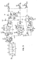
- FIGs. 2 and 3 show a BIU 20 in block diagram form and detailed schematic form, respectively.
- BIU 20 includes a clock/bit rate generator 28, microprocessor 30, random access memory (RAM) 32, programmable read-only memory (PROM) 34, program interval timer 36, modem interface 40 and subscriber device interface 42.
- the microprocessor 30 is an MOS Technology type 6502A NMOS microprocessor.
- An Intel type 8205 decoder is configured to select the various units peripheral to microprocessor 30 based on the state of address line A, 6- A,,.
- RAM 32' is a 2048 byte memory configured from four Intel type 2114 units to provide message buffering, program stack, and temporary storage.
- PROM 34 is a pair of 1024 byte Intel type 2708 units for providing storage of the BIU program, as shown in the Appendix.
- the program interval timer 36 is an MOS Technology type 6522 unit.
- the clock/bit rate generator 28 is a Motorola type 14411 unit, 1.8432 MHz crystal, and switch network arranged to provide a 1.8432 MHz clock signal to microprocessor 30, a 307.2 Kbps clock signal to the modem interface 40, and eight switch selectable clock signals for the device interface 42 (9600 bps, 4800 bps, 2400 bps, 1200 bps, 600 bps, 300 bps, 110 bps, 75 bps).
- the modem interface 40 includes a bus universal asynchronous receiver transmitter (UART) 50 and rf modulator 52 and demodulator 54.
- Bus UART 50 is a Motorola type 6850 asynchronous communications interface adapter (ACIA).
- ACIA asynchronous communications interface adapter
- the modulator 52 and demodulator 54 are shown in detailed schematic form in Figs. 4 and 5, respectively. Tables and II show the component values for the circuit elements in modulator 52 and demodulator 54, respectively.
- the device interface 42 includes an RS-232C serial data port 56 and an 8 bit full duplex parallel data port 58, although only one of these ports may be selected for operation at a time. In alternative embodiments, both or other conventional device interfaces may be used.
- the port 56 includes a device UART 60 and signal conversion unit 62, provided by a Motorola type 6850 ACIA unit and associated Signetics type 1488 and 1489 RS-232-C quad driver and quad receiver units, respectively. With this configuration, an Infoton type terminal for example, may readily be coupled to the BIU.
- the port 58 includes a parallel port interface 64 which is provided by the type 6522 unit used for the program interval timer 36.
- each BIU 20 asks its associated subscriber device 22 for the destination address (DA) of subsequent transmissions.
- the inquiry is accomplished by printing an inquiry code at the terminal and then waiting for a keyboard entry.
- BIU 20 transforms the operators response to a 16-bit DA word. The operator may change the entered DA at any time.
- the device 22 is a computer, either a similar dialogue occurs in software or the BIU is programmed to accept and supply completely formatted packets to/from the computer.
- All subsequent data from the subscriber device is then buffered in the BIU until an end-of- message, e.g. carriage return, is received or the buffer is filled.
- the destination address and the BIU's own 16-bit address (OA - originator address) are then appended to the message, together with other header data, to form a packet.
- the BIU reads the "receive key" line from the RF demodulator.
- receive key is "off” (i.e. no rf carrier is detected on outbound path 12) no other subscriber is currently transmitting.
- An “on” condition i.e. rf carrier is detected) for the receive key indicates that the bus is in use. This is the basic carrier sense mechanism.
- the BIU With the receive key off, the BIU lowers the "transmit key” line and the BIU begins to transmit the message. Multiple transmit buffers for the subscriber device inputs are used so that data may still be accepted from the device while the bus transmission is in progress.
- the transmitting BIU With its receiver enabled, the transmitting BIU sees the receive key go on after the round trip propagation delay of the inbound and outbound paths, and then begins to receive its own transmission. The four bytes (32 bits) are compared against those transmitted and, if identical, the transmitting BIU disables its receiver, and then transmits the remainder of the packet. If the test fails due to noise or another subscriber keying on during the propagation delay window, the BIU disables the transmitter, raises the transmit key signal (the receive key will then go high) and waits a pseudorandom time interval whose mean is approximately 400 microseconds. This random back-up feature is required to eliminate the possibility of two subscribers continually attempting simultaneous retransmissions.
- the transmitting BIU listens for only 4 bytes (32 bits), i.e. the destination address and originator address.
- the four byte collision window i.e. listening period
- the maximum end-to-end propagation delay of the bus which defines the limits of the time window in which other subscribers can possibly start transmissions without hearing, and therefore, deferring from transmitting their packets.
- This is the basic feature of the "listen-while-talk" protocol. Detection of collisions is insured since the first two characters of each message are the destination address and originator's address. This is a unique combination for each transmitting BIU.
- the collision window must commence after the time when the transmitter initiates a transmission on the inbound path, and at least t 1 from the packet start transmit time and extend at least t 2 from that transmit time, where t 1 equals the signal propagation time from the location of the transmitting BIU along the inbound path, the head end coupler, and along the outbound path back to the transmitting BIU, and where t 2 equals t, plus the signal propagation time along the inbound path between the transmitting BIU and the BIU located furthest from the head end along that path.
- Computer subscribers to the bus insert the destination address into each packet transmitted since in the present embodiment no dialogue with the computer itself is conducted to establish addresses.
- Computer subscribers also supply the byte count of the packet.
- the BIU accepts the proper number of bytes from the computer and then the packet is transmitted.
- Packet reception from the outbound path which originate from other subscribers occurs in the following manner.
- At power-up the receiver of each BIU is enabled.
- the BIU compares the first 16 bits of each received packet with its own address. If the address comparison is successful, (i.e. detects a match) subsequent characters from the network are buffered until the received byte count is satisfied or the receive buffer is full. If the comparison fails the BIU disables its receiver.
- the receive key signal is on. When the receive key returns to the off condition, i.e., the previous packet transmission is complete, the BIU re-enables the receiver and awaits reception of the next packet.
- the BIU clocks the data to the subscriber at the subscriber data rate. Again, multiple buffering of received packets is employed so that subsequent packets may be received from the network while the first is being clocked to the subscriber.
- the bus UART 50 For data received from the outbound path 12, the bus UART 50 performs serial-to-parallel conversion of data from the demodulator 52, checks each character for the proper number of start/stop bits, and generates an interrupt to the microprocessor 30 for each character received when the bus UART 50's receiver is enabled. Since the bus UART 50 is a full duplex device, data transmission can occur simultaneously. For data to be transmitted on inbound path 10, the microprocessor 30 first strobes each data word onto the bus UART 50 data bus lines. Then the bus UART 50 inserts start/stop bits, parity bits, performs the parallel-to-series conversion, and clocks the data to the modulator at the supplied transmit clock rate.
- bus UART 50 Since the bus UART 50 is double buffered on receive and transmit, a second character can be received while the first is being read by the microprocessor 30 or a second character can be loaded for transmission by the microprocessor 30 while the first is being clocked out to the modulator 52.
- the bus UART 50 also provides a status register which can be read by the microprocessor 30 to indicate:
- the device UART 60 used to interface the subscriber device 22 functions in conjunction with microprocessor 30 in a manner similar to UART 50.
- Serial data input by the device 22 is received by RS-232-C signal conversion hardware and then input to the device UART 60.
- each BIU performs the following functions in support of the basic packet transfer mechanism of "listen-while-talk":
- each BIU 20 performs the following functions to support its associated subscriber device:
- the present embodiment performs packet error checking and acknowledgements, retransmission of packets not acknowledged, and generation of status messages.
- the present embodiment provides an error correcting, packet communications protocol which includes the parts described in the following sections:
- the LWT protocol requires each subscriber to hear his own packet transmissions as well as those of all other subscribers.
- the BIU first checks the outbound channel to see if it is busy. If busy, the BIU simply waits until the line is free. When free, the first words of the packet are transmitted on the inbound channel and the BIU begins to see its own transmission on the outbound channel but delayed by the propagation time. The BIU then checks to see if the transmitted data is identical to that being received. If so, the BIU transmits the remainder of the packet knowing that all other subscribers are now waiting. If an error (either caused by noise or another subscriber's transmission), is detected, the BIU determines that a "collision" exists.
- the BIU stops transmitting, freeing the channel for other subscribers, and then backs off a random amount of time before retransmitting.
- the transmitting subscriber listens to his own transmission for at least the maximum propagation delay of the cable system, since this is the time window in which another subscriber could start before hearing the original transmission.
- the choice of the random back-off time uses a random number generator in the BIU with a fixed mean of about 400 microseconds.
- a random number generator in the BIU with a fixed mean of about 400 microseconds.
- collisions between packets and subsequent random retransmissions of the packet occur frequently.
- the probability that two subscribers start a packet transmission within the end-to-end propagation delay window increases.
- Fig. 15 shows the basic packet format for the LWT bus.
- Four 16 bits form the header portion, with the words being representative of the destination address (DA), originator address (OA), message type (MT), and byte (8 bits) count (BC).
- the header portion is followed by as many as 960 bits of message data and an 8 bit check-sum word used for error control.
- each BIU In addition to receiving its own transmission, each BIU examines the outbound channel for address matches or special message types. Subject to processing time limitations within the BIU, this message type and address filtering may readily be varied.
- each packet includes a sequence bit (1 or 0) and an 8 bit check-sum (CS).
- CS check-sum
- a receiver who acknowledges a packet but subsequently receives a packet with the same sequence bit must assume that the ACK packet was lost and must retransmit the ACK. If eight retries are unsuccessful, the transmitter deletes the packet from the transmit queue, and increments a "failed packet transmission" count. Each retry also causes a "retry" count to be incremented.
- Receivers may control the flow of data transmitted to them by selectively failing to acknowledge packets.
- the data flow is effectively controlled since the transmitter must retransmit the same packet.
- This aspect of the present invention is particularly useful in aiding transmissions from a computer subscriber device to an I/0 terminal subscriber device. In this case, the large buffers contained in the terminal BIU can free the computer from a relatively slow I/0 terminal.
- the programmable communications interface provides an opportunity to perform BIU 20 self-tests and report this information to a central status monitor and/or the connected subscriber device 22.
- the BIU performs self-tests in the background when it is not involved in the transmission or reception of data from either the network or the connected device. Specifically, the following tests are performed and results thereof maintained in memory:
- Each BIU provides an unsolicited status message approximately every minute based on interval timer 36 within the BIU.
- the status message is a unique message type on the LWT bus, and is characterized by an associated code word in the message type (MT) portion of the packet format.
- MT message type
- the BIU permits its connected subscriber to quickly change the destination address of packets it wishes to transmit.
- Computer subscribers may be in conversation with a number of other network subscribers. Thus, successive packets may contain a variety of destination addresses. Therefore, computer subscribers must completely format each packet before sending it to the BIU. The BIU simply accepts this formatted packet and faithfully transmits it onto the network.
- power-on reset or the manual reset switch causes the BIU 20 to be explicitly inquire as to the desired receiver. Valid responses are converted into destination addresses, and the BIU transmits a sign-on request message to the specified destination address. If no response is received within approximately fifteen seconds, a "SYSTEM NOT AVAILABLE" message is transferred to the device 22. If a response is received, the BIU 20 assumes a proper connection and a "LINK ACCEPTED" message is transferred to device 22.
- sign-on requests are immediately accepted if the device is not currently logically connected to another subscriber. Otherwise, a response to the sign-on request is not transmitted, and a "SYSTEM NOT AVAILABLE" message is transferred to the device that originated the sign-on request.
Description
- The present invention relates to communications systems, and more particularly, to time division, multiple access digital bus communications systems according to the preamble of
claim - The need for the efficient interconnection of computers and computer-related devices has become increasingly apparent with the development of computer technology. In particular, multiprocessor systems typically include a number of computers, often widely distributed, which are interconnected by a data bus to remote subscriber terminals and associated peripheral devices. With the developing technology, such terminals and devices have become diverse and capable of wide distribution. The inter-connection between such devices has become critical to the system use and performance, particularly in view of the need for adequate digital communication bandwidth, fast response time, high reliability, and the requirement for full access to all coupled but physically distributed devices. Conventional systems typically utilized circuit and message switching techniques. In addition, packet switching techniques have been utilized, although such systems have required relatively expensive store and forward nodes, which raise cost and reliability problems.
- Primarily, the conventional time division multiple access (TDMA) bus communications systems have relied on time slotting and assignments of these slots to transmitting subscribers, either permanently or at sign-on to the TDMA system. For example, see U.S. Patent No. 3,851,104, Willard, et al. While such systems are efficient for a population of high duty cycle traffic, large numbers of low duty cycle users, such as intercommunicating computers, quickly overburden many of the prior art TDMA systems having slots uniquely assigned to various subscribers.
- In view of this problem, bus contention protocols have been developed to more efficiently utilize the available band-width for computer and terminal communications. Generally, contention systems permit a user to gain access to the entire channel bandwidth for his message burst. In operation, a user having a message to send is permitted to transmit his message whenever he is ready. In the event another user is presently transmitting over the channel, or does so during the first user's transmission, then a message collision occurs. The system users must sense these collisions and, in response, retransmit their respective messages. Some systems provide random delays before retransmissions to avoid "butting", i.e. continual collisions between users.
- The contention protocols take advantage of the low duty cycle or "bursty" nature of data being transmitted from terminals and computers. For a large subscriber population of bursty users, the law of large numbers ensures that the channel bandwidth is only required to match the average aggregate data transmission rate of the entire population, rather than matching the sum of the peak rates for bursty subscribers as in the non-contention systems.
- Several approaches to the contention protocol have been developed in the prior art. For example, the ALOHA system (see N. Abrahamson "The ALOHA System - Another Alternative for Computer Communications", 1970 Fall Joint Computer Conference, AFIPS Conf. Proc. Vol. 37, AFIPS Press, 1970), describes an unslotted system wherein a plurality of remote stations are connected to a central station by way of a single radio channel. The various remote stations contend for the channel and transmit complete packets of data. In this unslotted configuration, the data packets are not synchronized between stations. When a collision is detected by failure to receive an acknowledgement from the central station, each of the transmitting terminals then retransmits its packet. With this configuration, the ALOHA system is relatively efficient for bursty terminals (e.g. a terminal duty cycle on the order of 196), compared with a system using separate channels for each station. However, a collision detected during a packet transmission results in the waste of the entire overlapping transmission intervals for the terminals (i.e. as much as two packet lengths), limiting maximum efficiency.
- Slotted (i.e. systems where the transmitted packets are synchronized from terminal to terminal) ALOHA systems have been suggested to provide an improvement in efficiency compared with unslotted ALOHA systems. In the latter configuration, the channel is divided into time slots of duration equal to the fixed data packet length. Each user is constrained to begin transmission of a data packet at the start of any time slot. When a collision occurs during a slot, the wasted time is equal to a single packet length, resulting in a substantially higher efficiency than the unslotted system.
- Another form of slotted, contention protocol communications system is disclosed in U.S. Patent No. 4 161 786 (corresponding to European Application 79 100 581.2), assigned to the assignee of the present application,
- The article "Time Division Digital Bus Techniques implemented on Coaxial Cable": Weisner et al, Procedures of Computer Networking Symposium, Dec. 15, 1977, discloses a multiple access bus communications system having features of the preamble of
claims - An unslotted, listen-while-talk (LWT), protocol, baseband communications system is also disclosed in U.S. Patent No. 4,063,220. This system includes a plurality of remote terminals coupled to a two-way communications medium. Prior to transmission, a terminal monitors the medium to detect activity (i.e. to sense whether the medium is currently busy). If the medium is busy, the terminal must defer at least until the current user is finished and the medium is no longer busy. If any terminal determines that the medium is not presently busy, that terminal may attempt to transmit on the medium.
- As a user transmits his message, he also monitors the medium. If the user does not detect any errors in his own transmission for the duration of the end-to-end propagation delay along the medium, then he determines that he has gained sole access to the medium and will successfully complete his packet transmission (unless due to noise interference other than from other users competing for the medium). Upon detection of a collision within the propagation delay interval, each colliding user aborts his transmission, and subsequently retransmits his message at a time when he determines that the medium is no longer busy. With this configuration, the time wasted during a collision is only the end-to-end propagation delay interval for the medium, in contrast to an interval equal to a single packet length as in the slotted ALOHA system, and an interval greater than a packet length as in the unslotted ALOHA system.
- Although relatively efficient compared with contention systems of the unslotted and slotted ALOHA types, the prior art LWT systems incorporating baseband transmission over a two-way medium generally require bidirectional repeaters located with minimum separations along the medium. This requirement is particularly important for relatively large systems where a terminal must perform the collision detection packet comparison operation with his own very high signal-to-noise ratio transmission with the substantially lower signal-to-noise ratio transmission which might come from a distant subscriber. In order to perform this operation, repeaters are provided to digitally regenerate the baseband signals on the medium, including reclocking of the signals to obtain full period bits with satisfactory rise and fall times. In addition, the repeaters must be spaced relatively close together on a multidrop medium in order to offset delay distortion. These requirements for close repeater spacing are costly in terms of equipment and reliability. Furthermore, the prior art baseband LWT systems are highly susceptible to low frequency noise often found in industrial and computer environments.
- It is an object to provide a radio frequency, multiple access bus communications system with listen-while-talk contention protocol over a system having unidirectional inbound and outbound signal paths connecting subscriber terminals, said system having a time of operation of the monitoring means which time is minimized. According to the invention, this object is stored by a multiple access bus communications system having the features of
claims - The system employing a LWT-protocol includes a plurality of remotely located terminals coupled to a communications bus. The bus includes a pair of oppositely'directed, unidirectional signal paths which are connected at one end so that one path is an inbound path to that end and the second is an outbound path from that end. Each of the remote terminals includes a bus interface unit (BIU) coupled to both the inbound and outbound paths at the remote location. By.way of example, the communications bus may comprise a pair of coaxial cables and conventional GATV components connected in a two-way cable distribution network.
- Each BIU is adapted to transmit and receive modulated carrier signals on the inbound and outbound paths, respectively. The bus interface unit transmits on the inbound cable and receives on the outbound cable.. No repeater or other head end equipment is necessary since the system is unslotted. and each BIU transmits and receives on the same frequency. In alternative embodiments, frequency conversion may be utilized at the junction of the inbound and outbound paths.
- In operation, when a terminal wishes to send a message to another terminal, the terminal's BIU initially performs an rf carrier sensing operation on the outbound path to make an initial determination as to whether or not any other subscriber is transmitting on the inbound path. In the event no carrier is detected, indicating that no other subscriber is using the inbound path,_the BIU confirms this initial determination by performing its listen-while-talk function by first transmitting a message addressed to the desired receiving terminal on the inbound path, and then monitoring (i.e., "listening-while-talking") the outbound path for at least the maximum (end-to-end) propagation delay of the entire bus. If the transmitted message is received intact by the transmitting terminal within this period, the transmitting terminal's BIU determines that no collision has taken place between its message and a message sent by another terminal, and that the transmitting terminal has gained access to the bus. Thereafter, the BIU may transmit any remaining portion of its message packet on the inbound path. However, in the event a collision is detected, the transmitting terminal's BIU aborts its transmission and then backs off for a random time period before again attempting to gain access to the bus and transmit its message.
- Thus, with this multiple access configuration, all subscribers (i.e. terminals) share the digital channel and have access to all information on the channel and are capable of transmitting to all other subscribers on the channel. In addition, no subscriber starts a transmission unless, to the best of the subscriber's knowledge, the channel is not in use. Generally, this determination is made by sensing carrier on the outbound path.
- With this configuration, a large number of low duty cycle, or "bursty", subscribers may be accommodated by determining a bandwidth appropriate to match the average aggregate data transmission rate of the entire population, rather than match the sum of the peak rates for bursty subscribers, as in conventional systems. Through the use of message transmission by modulated carrier signal on a unidirectional signal path, the present invention is very efficient, since the transmitted data is effected relatively little by signal-to-noise degradation on the line, and no repeaters are required. Furthermore, by utilizing the unidirectional signal paths relatively large bandwidth can be used and thereby increasing the data transfer capability. As a further advantage of the present system, the modulated rf signals are relatively immune to error generation in the data due to interference from external noise sources compared with comparable data signals used in baseband systems.
- According to the invention, the shortened collision window allows to minimize the required time of operation of the monitoring means which permits economies of equipment compared with the systems of the prior art.
- The foregoing and other objects of the invention, the various features thereof, as well as the invention itself, may be more fully understood from the following description, when read together with the accompanying drawings in which:
- Fig. 1 shows, in block diagram form, an exemplary communications system embodying the present invention;
- Fig. 2 shows, in block diagram form, the bus interface unit (BIU) of the system of Fig. 1;
- Fig. 3 shows, in schematic form, the bus interface unit (BIU) of the system of Fig. 1;
- Fig. 4 shows, in schematic form, the modulator of the BIU of Fig. 2;
- Fig. 5 shows, in schematic form, the demodulator of the BIU of Fig. 2;
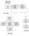
- Fig. 6 shows, in block form, the functional operation of the BIU of Fig. 2;
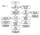
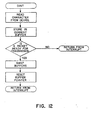
- Figs. 7-14 show, in detailed flow chart form, the functional operation blocks of Fig. 6; and
- Fig. 15 shows the packet format for the system of Fig. 1.
- Fig. 1 shows a
communications system 5 embodying the present invention. This embodiment includes a communications bus comprising an inboundunidirectional signal path 10 and an outboundunidirectional signal path 12 and aunidirectional path coupler 14 for transferring signals from the inbound path to the outbound path at the system head-end. The inbound andoutbound paths paths coupler 14 include a single coaxial cable and associated conventional unidirectional coupling devices (at each subscriber location). - At each subscriber location, a subscriber terminal having a bus interface unit (BIU) and an associated subscriber device may be coupled to
paths reference designation 20 and a suffix representative of one of the exemplary locations A, B, C, and D. Similarly, the subscriber devices are denoted byreference designation 22 and a location-keyed suffix. EachBIU 20 receives data from its associatedsubscriber device 22, formats that data into a standard packet with header information (including originating and destination terminal addresses) and buffers that data packet until transmission time. At that time, theBIU 20 transmits the addressed data packet on theinbound path 10. - In addition, each
BIU 20 also scans each packet of data on the outbound path for its own address. If a packet with the address for that BIU is detected, then the BIU reads the complete packet from theoutbound path 12 into a buffer, error checks the packet, acknowledges the transmission, and then clocks the data to thesubscriber device 22 at a predetermined data rate. - Figs. 2 and 3 show a
BIU 20 in block diagram form and detailed schematic form, respectively.BIU 20 includes a clock/bit rate generator 28,microprocessor 30, random access memory (RAM) 32, programmable read-only memory (PROM) 34,program interval timer 36,modem interface 40 andsubscriber device interface 42. Themicroprocessor 30 is an MOS Technology type 6502A NMOS microprocessor. AnIntel type 8205 decoder is configured to select the various units peripheral tomicroprocessor 30 based on the state of address line A,6-A,,. RAM 32' is a 2048 byte memory configured from fourIntel type 2114 units to provide message buffering, program stack, and temporary storage.PROM 34 is a pair of 1024byte Intel type 2708 units for providing storage of the BIU program, as shown in the Appendix. Theprogram interval timer 36 is anMOS Technology type 6522 unit. The clock/bit rate generator 28 is aMotorola type 14411 unit, 1.8432 MHz crystal, and switch network arranged to provide a 1.8432 MHz clock signal tomicroprocessor 30, a 307.2 Kbps clock signal to themodem interface 40, and eight switch selectable clock signals for the device interface 42 (9600 bps, 4800 bps, 2400 bps, 1200 bps, 600 bps, 300 bps, 110 bps, 75 bps). - The
modem interface 40 includes a bus universal asynchronous receiver transmitter (UART) 50 andrf modulator 52 anddemodulator 54.Bus UART 50 is aMotorola type 6850 asynchronous communications interface adapter (ACIA). Themodulator 52 anddemodulator 54 are shown in detailed schematic form in Figs. 4 and 5, respectively. Tables and II show the component values for the circuit elements inmodulator 52 anddemodulator 54, respectively. - As shown in Fig. 2, the
device interface 42 includes an RS-232Cserial data port 56 and an 8 bit full duplexparallel data port 58, although only one of these ports may be selected for operation at a time. In alternative embodiments, both or other conventional device interfaces may be used. Theport 56 includes adevice UART 60 andsignal conversion unit 62, provided by aMotorola type 6850 ACIA unit and associatedSignetics type port 58 includes aparallel port interface 64 which is provided by thetype 6522 unit used for theprogram interval timer 36. - In operation, on power-up or when reset, each
BIU 20 asks its associatedsubscriber device 22 for the destination address (DA) of subsequent transmissions. Where thedevice 22 is an attended data

BIU 20 transforms the operators response to a 16-bit DA word. The operator may change the entered DA at any time. Where thedevice 22 is a computer, either a similar dialogue occurs in software or the BIU is programmed to accept and supply completely formatted packets to/from the computer. - All subsequent data from the subscriber device is then buffered in the BIU until an end-of- message, e.g. carriage return, is received or the buffer is filled. The destination address and the BIU's own 16-bit address (OA - originator address) are then appended to the message, together with other header data, to form a packet.
- Once a packet has been assembled for transmission, the BIU reads the "receive key" line from the RF demodulator. When the receive key is "off" (i.e. no rf carrier is detected on outbound path 12) no other subscriber is currently transmitting. An "on" condition (i.e. rf carrier is detected) for the receive key indicates that the bus is in use. This is the basic carrier sense mechanism. With the receive key off, the BIU lowers the "transmit key" line and the BIU begins to transmit the message. Multiple transmit buffers for the subscriber device inputs are used so that data may still be accepted from the device while the bus transmission is in progress.
- With its receiver enabled, the transmitting BIU sees the receive key go on after the round trip propagation delay of the inbound and outbound paths, and then begins to receive its own transmission. The four bytes (32 bits) are compared against those transmitted and, if identical, the transmitting BIU disables its receiver, and then transmits the remainder of the packet. If the test fails due to noise or another subscriber keying on during the propagation delay window, the BIU disables the transmitter, raises the transmit key signal (the receive key will then go high) and waits a pseudorandom time interval whose mean is approximately 400 microseconds. This random back-up feature is required to eliminate the possibility of two subscribers continually attempting simultaneous retransmissions.
- With this configuration, the transmitting BIU listens for only 4 bytes (32 bits), i.e. the destination address and originator address. The four byte collision window (i.e. listening period) is longer than the maximum end-to-end propagation delay of the bus, which defines the limits of the time window in which other subscribers can possibly start transmissions without hearing, and therefore, deferring from transmitting their packets. This is the basic feature of the "listen-while-talk" protocol. Detection of collisions is insured since the first two characters of each message are the destination address and originator's address. This is a unique combination for each transmitting BIU.
- In accordance with the present invention, different length collision windows may be utilized depending on the system geometry. The collision window must commence after the time when the transmitter initiates a transmission on the inbound path, and at least t1 from the packet start transmit time and extend at least t2 from that transmit time, where t1 equals the signal propagation time from the location of the transmitting BIU along the inbound path, the head end coupler, and along the outbound path back to the transmitting BIU, and where t2 equals t, plus the signal propagation time along the inbound path between the transmitting BIU and the BIU located furthest from the head end along that path.
- Computer subscribers to the bus insert the destination address into each packet transmitted since in the present embodiment no dialogue with the computer itself is conducted to establish addresses. Computer subscribers also supply the byte count of the packet. The BIU then accepts the proper number of bytes from the computer and then the packet is transmitted.
- Packet reception from the outbound path which originate from other subscribers occurs in the following manner.,At power-up the receiver of each BIU is enabled. The BIU compares the first 16 bits of each received packet with its own address. If the address comparison is successful, (i.e. detects a match) subsequent characters from the network are buffered until the received byte count is satisfied or the receive buffer is full. If the comparison fails the BIU disables its receiver. During any bus transmission, the receive key signal is on. When the receive key returns to the off condition, i.e., the previous packet transmission is complete, the BIU re-enables the receiver and awaits reception of the next packet.
- Other receive filtering criteria are possible. Most systems require special message types (status, assignment) or filtering on originator's address as opposed to or in addition to the destination address in the packet. These features are readily programmed within the BIU.
- Once a complete packet has been received, the BIU clocks the data to the subscriber at the subscriber data rate. Again, multiple buffering of received packets is employed so that subsequent packets may be received from the network while the first is being clocked to the subscriber.
- For data received from the
outbound path 12, thebus UART 50 performs serial-to-parallel conversion of data from thedemodulator 52, checks each character for the proper number of start/stop bits, and generates an interrupt to themicroprocessor 30 for each character received when thebus UART 50's receiver is enabled. Since thebus UART 50 is a full duplex device, data transmission can occur simultaneously. For data to be transmitted oninbound path 10, themicroprocessor 30 first strobes each data word onto thebus UART 50 data bus lines. Then thebus UART 50 inserts start/stop bits, parity bits, performs the parallel-to-series conversion, and clocks the data to the modulator at the supplied transmit clock rate. Since thebus UART 50 is double buffered on receive and transmit, a second character can be received while the first is being read by themicroprocessor 30 or a second character can be loaded for transmission by themicroprocessor 30 while the first is being clocked out to themodulator 52. - The
bus UART 50 also provides a status register which can be read by themicroprocessor 30 to indicate: - (1) the receiving holding register is full (this also causes an interrupt);
- (2) the transmitter holding register is empty;
- (3) the status of the "receive key" signal (logic "1" indicates the network is available, logic "0" indicates the network is busy);
- (4) a false start bit was detected;
- (5) the receiver holding has been overrun by a second character since the first was not read by a peripheral device;
- (6) a parity error was detected;
- (7) an interrupt was generated.
- The
device UART 60 used to interface thesubscriber device 22 functions in conjunction withmicroprocessor 30 in a manner similar toUART 50. Serial data input by thedevice 22 is received by RS-232-C signal conversion hardware and then input to thedevice UART 60. - In the present configuration, each BIU performs the following functions in support of the basic packet transfer mechanism of "listen-while-talk":
- (1) Initialize the microprocessor and its peripheral units at power-on and when the BIU is reset;
- (2) move packets from the
buffer memory 32 to thebus UART 50; - (3) check each packet transmitted to insure that collisions have not occurred. If a collision occurs, randomly back-off and then automatically retransmit the packet;
- (4) receive properly addressed packets from the
inbound path 10 and deposit them inmemory 32. - In general, the device software.is specific to the
particular subscriber device 22 being interfaced to a location along the bus. However, eachBIU 20 performs the following functions to support its associated subscriber device: - (1).Move received packets from the
memory 32 to the connecteddevice 22; - (2) accept data from the connected
device 22 and format complete subscriber messages into the network packet; - (3) support a dialogue with terminal subscribers to establish destination address of subsequent data.
- In addition, the present embodiment performs packet error checking and acknowledgements, retransmission of packets not acknowledged, and generation of status messages.
- The above functions are depicted generally in the function block diagrams of Figs. 6A-C, and in detail in the flow-charts of Figs. 7-14, where each of Figs. 7-14 corresponds to one of the blocks of Figs. 6A-C.
- The present embodiment provides an error correcting, packet communications protocol which includes the parts described in the following sections:
- (1) Packet Transfer - This part of the protocol provides the listen-while-talk (LWT) mechanism for sharing the digital channel among a large number of subscribers.
- (2) Error Correction -This part of the protocol provides end-to-end (transmitting BIU to receiving BIU) error detection and automatic retransmission of packets in error. An 8-bit check-sum is used for error detection.
- (3) Flow Control - Receiving subscribers to the bus may control the rate at which buffers are transmitted in point-to-point conversations. Through the use of large buffers in the BIU's and this flow control mechanism, receiver overrun is avoided.
- (4) Status - The
BIU 20 automatically provides unsolicited status messages at approximately one minute intervals. Status messages contain the results of BIU self tests (e.g. memory and peripheral status register checks) and the current state of the connecteddevice 22. - (5) Networking Addressing - Each
subscriber device 22 may establish any change destigatioh addresses. - The LWT protocol requires each subscriber to hear his own packet transmissions as well as those of all other subscribers. When a BIU is ready to transmit, the BIU first checks the outbound channel to see if it is busy. If busy, the BIU simply waits until the line is free. When free, the first words of the packet are transmitted on the inbound channel and the BIU begins to see its own transmission on the outbound channel but delayed by the propagation time. The BIU then checks to see if the transmitted data is identical to that being received. If so, the BIU transmits the remainder of the packet knowing that all other subscribers are now waiting. If an error (either caused by noise or another subscriber's transmission), is detected, the BIU determines that a "collision" exists. In response to this determination, the BIU stops transmitting, freeing the channel for other subscribers, and then backs off a random amount of time before retransmitting. Thus, the transmitting subscriber listens to his own transmission for at least the maximum propagation delay of the cable system, since this is the time window in which another subscriber could start before hearing the original transmission.
- In the present embodiment, the choice of the random back-off time uses a random number generator in the BIU with a fixed mean of about 400 microseconds. In heavily loaded systems, collisions between packets and subsequent random retransmissions of the packet occur frequently. In other words, as the system becomes busier, the probability that two subscribers start a packet transmission within the end-to-end propagation delay window increases.
- Fig. 15 shows the basic packet format for the LWT bus. Four 16 bits form the header portion, with the words being representative of the destination address (DA), originator address (OA), message type (MT), and byte (8 bits) count (BC). The header portion is followed by as many as 960 bits of message data and an 8 bit check-sum word used for error control.
- In addition to receiving its own transmission, each BIU examines the outbound channel for address matches or special message types. Subject to processing time limitations within the BIU, this message type and address filtering may readily be varied.
- Although the LWT packet transfer protocol provides some error detection on the front end of each packet and subsequent retransmission, an error correcting end-to-end technique is used in addition. More particularly, an acknowledgement for each packet transmitted without error. Automatic retransmission is provided for each packet not acknowledged. To provide this error correction, each packet includes a sequence bit (1 or 0) and an 8 bit check-sum (CS). When the packet is received at the destination address, the check-sum is compared with received packet. If the check-sum is correct for the received packet, the receiver transmits an ACK message to the originating terminal containing the same sequence bit as that received. Thus, a transmitter whose packet is not acknowledged must retransmit the original packet after waiting a fixed time interval. A receiver who acknowledges a packet but subsequently receives a packet with the same sequence bit must assume that the ACK packet was lost and must retransmit the ACK. If eight retries are unsuccessful, the transmitter deletes the packet from the transmit queue, and increments a "failed packet transmission" count. Each retry also causes a "retry" count to be incremented.
- Receivers may control the flow of data transmitted to them by selectively failing to acknowledge packets. The data flow is effectively controlled since the transmitter must retransmit the same packet. This aspect of the present invention is particularly useful in aiding transmissions from a computer subscriber device to an I/0 terminal subscriber device. In this case, the large buffers contained in the terminal BIU can free the computer from a relatively slow I/0 terminal.
- The programmable communications interface provides an opportunity to perform
BIU 20 self-tests and report this information to a central status monitor and/or theconnected subscriber device 22. To this end, the BIU performs self-tests in the background when it is not involved in the transmission or reception of data from either the network or the connected device. Specifically, the following tests are performed and results thereof maintained in memory: - (1) The BIU performs a complete memory test of all random access memory (RAM) 32 locations.
- (2) The BIU examines the status registers contained in the
parallel port 58,serial port 56, andinterval timer 36. The comparison is performed to determine differences between the expected values and the actual values of each register. - In addition, the following status data is maintained between status messages:
- (1) A count of the number of unacknowledged packets.
- (2) A count of the number of packets that were discarded because eight retransmissions were attempted but not acknowledged.
- The results of each of these tests, the status data, the current value of the device status register in either
parallel port 58 orserial port 56, the number of packets queued for transmission, and the number of queued received packets are reported in each transmitted status message. Each BIU provides an unsolicited status message approximately every minute based oninterval timer 36 within the BIU. - The status message is a unique message type on the LWT bus, and is characterized by an associated code word in the message type (MT) portion of the packet format.
- The BIU permits its connected subscriber to quickly change the destination address of packets it wishes to transmit. Computer subscribers may be in conversation with a number of other network subscribers. Thus, successive packets may contain a variety of destination addresses. Therefore, computer subscribers must completely format each packet before sending it to the BIU. The BIU simply accepts this formatted packet and faithfully transmits it onto the network.
- For attended terminal devices, power-on reset or the manual reset switch causes the
BIU 20 to be explicitly inquire as to the desired receiver. Valid responses are converted into destination addresses, and the BIU transmits a sign-on request message to the specified destination address. If no response is received within approximately fifteen seconds, a "SYSTEM NOT AVAILABLE" message is transferred to thedevice 22. If a response is received, theBIU 20 assumes a proper connection and a "LINK ACCEPTED" message is transferred todevice 22. - For unattended devices, i.e. printers, cassette recorders, discs, etc., sign-on requests are immediately accepted if the device is not currently logically connected to another subscriber. Otherwise, a response to the sign-on request is not transmitted, and a "SYSTEM NOT AVAILABLE" message is transferred to the device that originated the sign-on request.
-


Claims (7)
said transmitter control means being operative to activate said transmitter means only during said identified times, and being responsive to said collision detection means to disable said transmitter means following reception of said packet in its entirety by said receiver means when said detected modulation and said packet header portion match, and to disable said transmitter means immediately when said detected modulation and said packet portion fail to match, characterized in that said collision window commences after the time when said transmitter means initiates a transmission on said inbound path and at least as early as t, from the time when said transmitter means initiates transmission of said inbound path (1µ), and extends until at least t2 after said transmission initiation time, where t1 equals the signal propagation time along said inbound path (10), said path coupling means (14), and said outbound path (12) from the location of said one BIU back to said one BIU, and t2 equals the signal propagation time along said inbound path (10), said path coupling means (14) and said outbound path (12) from the location of the BIU farthest from said path coupling means (14) back to the location of said one BIU.
Applications Claiming Priority (2)
| Application Number | Priority Date | Filing Date | Title |
|---|---|---|---|
| US05/890,479 US4210780A (en) | 1978-03-27 | 1978-03-27 | Multiple access digital communications system |
| US890479 | 1978-03-27 |
Publications (3)
| Publication Number | Publication Date |
|---|---|
| EP0004376A2 EP0004376A2 (en) | 1979-10-03 |
| EP0004376A3 EP0004376A3 (en) | 1979-10-31 |
| EP0004376B1 true EP0004376B1 (en) | 1982-09-29 |
Family
ID=25396737
Family Applications (1)
| Application Number | Title | Priority Date | Filing Date |
|---|---|---|---|
| EP79100859A Expired EP0004376B1 (en) | 1978-03-27 | 1979-03-21 | Multiple access bus communications system |
Country Status (5)
| Country | Link |
|---|---|
| US (1) | US4210780A (en) |
| EP (1) | EP0004376B1 (en) |
| JP (1) | JPS54154908A (en) |
| CA (1) | CA1115346A (en) |
| DE (1) | DE2963763D1 (en) |
Families Citing this family (91)
| Publication number | Priority date | Publication date | Assignee | Title |
|---|---|---|---|---|
| CH632365A5 (en) * | 1978-01-30 | 1982-09-30 | Patelhold Patentverwertung | DATA EXCHANGE PROCESS BETWEEN MULTIPLE PARTNERS. |
| GB2050763B (en) * | 1979-04-04 | 1983-02-09 | Philips Electronic Associated | Transmitter queuing system |
| US4402073A (en) * | 1980-03-11 | 1983-08-30 | Vanderhoff Communications Ltd. | Speech and data communication network |
| EP0052456A1 (en) * | 1980-11-10 | 1982-05-26 | Xerox Corporation | A shared-line communication system, and components therefor |
| JPS5816338A (en) * | 1980-11-10 | 1983-01-31 | ゼロツクス・コ−ポレ−シヨン | Receiver for common line |
| US4379294A (en) * | 1981-02-12 | 1983-04-05 | Electric Power Research Institute, Inc. | Data highway access control system |
| US4387441A (en) * | 1981-04-16 | 1983-06-07 | Ncr Corporation | Data processing system wherein at least one subsystem has a local memory and a mailbox memory within the local memory for storing header information |
| US4494185A (en) * | 1981-04-16 | 1985-01-15 | Ncr Corporation | Data processing system employing broadcast packet switching |
| US4432088A (en) * | 1981-04-30 | 1984-02-14 | The United States Of America As Represented By The United States Department Of Energy | Carrier sense data highway system |
| FR2507415A1 (en) * | 1981-06-05 | 1982-12-10 | Ryckeboer Christian | METHOD AND DEVICE FOR ASYNCHRONOUS SERIAL COMMUNICATION OF MULTIPOINTS TYPE OF MULTIPLE LOGIC RECEIVER-RECEIVERS |
| US4503533A (en) * | 1981-08-20 | 1985-03-05 | Stanford University | Local area communication network utilizing a round robin access scheme with improved channel utilization |
| US4439763A (en) * | 1981-09-03 | 1984-03-27 | Bell Telephone Laboratories, Incorporated | Collision avoiding system and protocol for a multiple access digital communications system |
| US4412326A (en) * | 1981-10-23 | 1983-10-25 | Bell Telephone Laboratories, Inc. | Collision avoiding system, apparatus and protocol for a multiple access digital communications system including variable length packets |
| JPS5875350A (en) * | 1981-10-30 | 1983-05-07 | Fuji Xerox Co Ltd | Transmitting system of digital signal |
| US4464749A (en) * | 1982-02-24 | 1984-08-07 | General Electric Company | Bi-directional token flow system |
| US4439856A (en) * | 1982-02-24 | 1984-03-27 | General Electric Company | Bimodal bus accessing system |
| US4630256A (en) * | 1982-03-12 | 1986-12-16 | At&T Bell Laboratories | Bidirectional dual network |
| EP0102384B1 (en) * | 1982-03-12 | 1988-01-07 | Western Electric Company, Incorporated | Bidirectional dual network |
| US4719567A (en) * | 1982-04-29 | 1988-01-12 | Motorola, Inc. | Method and apparatus for limiting bus utilization |
| US4476467A (en) * | 1982-06-08 | 1984-10-09 | Cromemco Inc. | Random entry intercomputer network with collision prevention |
| IT1157035B (en) * | 1982-06-09 | 1987-02-11 | Cselt Centro Studi Lab Telecom | VARIABLEBAND COLLECTION AND SWITCHING SYSTEM FOR VOICES AND DATA |
| US4574378A (en) * | 1982-06-14 | 1986-03-04 | Nec Corporation | Multiple access system and method |
| US4532626A (en) * | 1982-07-19 | 1985-07-30 | At&T Bell Laboratories | Collision avoiding system and protocol for a two path multiple access digital communications system |
| US4500989A (en) * | 1982-08-02 | 1985-02-19 | Dahod Ashraf M | Digital communication system |
| DE3382291D1 (en) * | 1982-08-19 | 1991-06-27 | Computer Automation | TRANSMISSION INTERFACE. |
| US4498168A (en) * | 1982-12-13 | 1985-02-05 | Trw Inc. | Communication network and method for its use |
| JPS59115645A (en) * | 1982-12-22 | 1984-07-04 | Toshiba Corp | Information transmission system |
| US4573045A (en) * | 1983-01-24 | 1986-02-25 | Intel Corporation | Collision detection method using CRC code |
| US4574284A (en) * | 1983-01-26 | 1986-03-04 | Trw Inc. | Communication bus interface unit |
| US4543654A (en) * | 1983-02-03 | 1985-09-24 | Wang Laboratories, Inc. | Interfacing a communication network |
| US4498169A (en) * | 1983-03-14 | 1985-02-05 | Scientific Atlanta, Inc. | Multiaccess broadcast communication system |
| US4536838A (en) * | 1983-03-24 | 1985-08-20 | Mds Qantel, Inc. | Multi-processor system with communication controller using poll flags for non-contentious slot reservation |
| US4510599A (en) * | 1983-04-04 | 1985-04-09 | General Electric Company | Prioritized unidirectional distributed bus accessing system |
| JPS59202753A (en) * | 1983-05-02 | 1984-11-16 | Toshiba Corp | Data communication system |
| US4581735A (en) * | 1983-05-31 | 1986-04-08 | At&T Bell Laboratories | Local area network packet protocol for combined voice and data transmission |
| US4517670A (en) * | 1983-06-15 | 1985-05-14 | General Electric Company | Preemptive bid communication system |
| US4569046A (en) * | 1983-07-18 | 1986-02-04 | Northern Telecom Limited | Method of, and a terminal for, transmitting bytes to a bus |
| US4910732A (en) * | 1983-09-20 | 1990-03-20 | Siegfried Schwarz | Onechip-computers as network-controller and computer |
| US4622664A (en) * | 1983-10-19 | 1986-11-11 | Japanese National Railways | Channel control system for loop type signal transmission channel |
| FR2554294B1 (en) * | 1983-10-28 | 1990-03-16 | Dassault Electronique | DEVICE FOR THE EXCHANGE OF DIGITAL INFORMATION BETWEEN SEVERAL STATIONS |
| US4542502A (en) * | 1983-12-30 | 1985-09-17 | At&T Bell Laboratories | Reconfigurable collision avoiding system, station and protocol for a two path multiple access digital communications system |
| US5448593A (en) * | 1984-03-06 | 1995-09-05 | Cyplex Corporation | Frequency hopping time-diversity communications systems and transceivers for local area networks |
| US4602364A (en) * | 1984-04-23 | 1986-07-22 | Codex Corporation | Local area data communication network |
| US4627050A (en) * | 1984-05-22 | 1986-12-02 | Rolm Corporation | Time division multiplexed computerized branch exchange |
| ATE82097T1 (en) * | 1984-12-03 | 1992-11-15 | Univ Western Australia | LOG FOR QUEUE. |
| CA1263721A (en) | 1985-10-18 | 1989-12-05 | Owen Lloyd Nelson | Communication system for the transfer of small digital message blocks and large digital message blocks |
| US4751701A (en) * | 1985-11-14 | 1988-06-14 | Hughes Network Systems, Inc. | TDM collision detector |
| US4688213A (en) * | 1985-11-29 | 1987-08-18 | Rca Corporation | Asynchronous random access communication system with collision resolution based on time of arrival |
| US4750171A (en) * | 1986-07-11 | 1988-06-07 | Tadiran Electronics Industries Ltd. | Data switching system and method |
| US4774707A (en) * | 1986-09-10 | 1988-09-27 | General Electric Company | Random access communication system with scheduled data transmission and asynchronous contention scheduling |
| CA1250900A (en) * | 1986-11-18 | 1989-03-07 | Northern Telecom Limited | Private cellular system |
| US4745599A (en) * | 1987-01-05 | 1988-05-17 | General Electric Company | Random access communication system with contention scheduling of subpacketized data transmissions and scheduled retransmission of unsuccessful subpackets |
| SE456629B (en) * | 1987-02-27 | 1988-10-17 | Ellemtel Utvecklings Ab | PROCEDURE AND DEVICE FOR TRANSFERING INFORMATION FROM A BUS SYSTEM |
| FR2631183B1 (en) * | 1988-05-06 | 1991-02-22 | Compex | METHOD AND DEVICE FOR ASYNCHRONOUS PACKET DATA TRANSMISSION |
| US4945355A (en) * | 1988-10-27 | 1990-07-31 | Motorola, Inc. | System for cooperatively reassigning duties in a multiple controller environment |
| DE68916231T2 (en) * | 1989-03-23 | 1995-02-02 | Ibm | Method and device for multiple access with distributed queues in a communication system. |
| US5499336A (en) * | 1991-08-16 | 1996-03-12 | Robert Bosch Gmbh | Monitoring a computer network |
| US5276703A (en) * | 1992-01-13 | 1994-01-04 | Windata, Inc. | Wireless local area network communications system |
| US5335226A (en) * | 1992-06-18 | 1994-08-02 | Digital Equipment Corporation | Communications system with reliable collision detection method and apparatus |
| US5267237A (en) * | 1992-07-07 | 1993-11-30 | Digital Equipment Corporation | Collison detection and signaling circuit |
| US5311512A (en) * | 1992-12-14 | 1994-05-10 | At&T Bell Laboratories | Multiple-master digital communication technique utilizing a dedicated contention bus |
| US5764629A (en) * | 1996-03-08 | 1998-06-09 | Dsc Communications Corporation | Method and apparatus for avoiding collisions in an electronic business set terminal |
| US20080002735A1 (en) * | 1997-04-01 | 2008-01-03 | Paradox Security Systems Ltd. | Device network |
| US6475089B1 (en) * | 1998-01-29 | 2002-11-05 | Kabushiki Kaisha Sega Enterprises | Game system |
| US6201817B1 (en) | 1998-05-28 | 2001-03-13 | 3Com Corporation | Memory based buffering for a UART or a parallel UART like interface |
| SG87784A1 (en) | 1998-12-09 | 2002-04-16 | Kent Ridge Digital Labs | Csma/cd wireless lan |
| US6454561B1 (en) * | 1999-05-19 | 2002-09-24 | Lancaster Colony Corp. | Candle wick clip, candle and method |
| US6718397B1 (en) | 2000-01-05 | 2004-04-06 | Yijun Zhao | Network adapter for providing initialization and protocol translation between a microprocessor and a network interface |
| WO2001053040A1 (en) * | 2000-01-19 | 2001-07-26 | Rodel Holdings, Inc. | Printing of polishing pads |
| GB2358997B (en) * | 2000-02-04 | 2003-08-06 | Motorola Ltd | Group communications system with assignable transmission authority |
| WO2002044925A1 (en) * | 2000-11-28 | 2002-06-06 | P & S Datacom Corporation | Microprocessor-interface communication protocol |
| SE0004832L (en) * | 2000-12-22 | 2002-02-26 | Ericsson Telefon Ab L M | Digital bus system |
| US20020124007A1 (en) * | 2001-03-02 | 2002-09-05 | Wuhan P&S Electronics Company Ltd. | Network server and database therein |
| KR100434270B1 (en) | 2001-05-30 | 2004-06-04 | 엘지전자 주식회사 | Control System for Home Appliance Network |
| US7352771B2 (en) * | 2002-10-08 | 2008-04-01 | Colder Products Company | Data collision detection device and method |
| DE10360873B4 (en) * | 2003-12-23 | 2006-08-10 | Airbus Deutschland Gmbh | Method for operating a terminal, terminal and data bus system |
| US20060120323A1 (en) * | 2004-12-07 | 2006-06-08 | Fengji Ye | Media access controller with enhanced data unit retransmission for broadband wireless communication and method |
| US7489629B2 (en) * | 2004-12-07 | 2009-02-10 | Intel Corporation | Methods and media access controller for broadband wireless communications with variable data unit size and delayed data unit construction |
| US7965734B2 (en) * | 2005-12-15 | 2011-06-21 | Paradox Security Systems Ltd. | Device network interface |
| US7634016B2 (en) * | 2006-04-25 | 2009-12-15 | Microsoft Corporation | Variable OFDM subchannel coding and modulation |
| US7933344B2 (en) * | 2006-04-25 | 2011-04-26 | Mircosoft Corporation | OFDMA based on cognitive radio |
| US8189621B2 (en) | 2006-05-12 | 2012-05-29 | Microsoft Corporation | Stack signaling to application with lack of requested bandwidth |
| US8144793B2 (en) | 2006-12-12 | 2012-03-27 | Microsoft Corporation | Cognitive multi-user OFDMA |
| US7929623B2 (en) * | 2007-03-30 | 2011-04-19 | Microsoft Corporation | FEC in cognitive multi-user OFDMA |
| US7970085B2 (en) | 2007-05-08 | 2011-06-28 | Microsoft Corporation | OFDM transmission and reception for non-OFDMA signals |
| US8374130B2 (en) | 2008-01-25 | 2013-02-12 | Microsoft Corporation | Orthogonal frequency division multiple access with carrier sense |
| US8855087B2 (en) * | 2008-12-18 | 2014-10-07 | Microsoft Corporation | Wireless access point supporting control by multiple applications |
| US9445432B2 (en) | 2010-06-25 | 2016-09-13 | Microsoft Technology Licensing, Llc | Fine-grained channel access in wireless networks |
| WO2016161980A1 (en) | 2015-04-10 | 2016-10-13 | 中兴通讯股份有限公司 | Unlicensed carrier contention method and apparatus |
| US10897477B2 (en) * | 2016-07-01 | 2021-01-19 | Texas Instruments Incorporated | Relay-attack resistant communications |
| KR101840558B1 (en) * | 2016-08-17 | 2018-03-20 | 엘지전자 주식회사 | Electronic device and communication method thereof |
Family Cites Families (7)
| Publication number | Priority date | Publication date | Assignee | Title |
|---|---|---|---|---|
| JPS5444161B2 (en) * | 1973-09-08 | 1979-12-24 | ||
| US3922496A (en) * | 1974-02-11 | 1975-11-25 | Digital Communications Corp | TDMA satellite communications system with guard band obviating ongoing propagation delay calculation |
| US3958083A (en) * | 1974-02-26 | 1976-05-18 | Fujitsu Ltd. | Acquisition system for the SDMA/TDMA satellite communication system |
| US4063220A (en) * | 1975-03-31 | 1977-12-13 | Xerox Corporation | Multipoint data communication system with collision detection |
| CA1055172A (en) * | 1976-02-09 | 1979-05-22 | Her Majesty The Queen In Right Of Canada As Represented By The Minister Of National Defence Of Her Majesty's Canadian Government | Satellite communications system |
| CH607474A5 (en) * | 1976-11-12 | 1978-12-29 | Ibm | |
| US4115661A (en) * | 1977-03-21 | 1978-09-19 | Satellite Business Systems | Single channel per burst TDMA multiple transponder network |
-
1978
- 1978-03-27 US US05/890,479 patent/US4210780A/en not_active Expired - Lifetime
-
1979
- 1979-03-21 EP EP79100859A patent/EP0004376B1/en not_active Expired
- 1979-03-21 DE DE7979100859T patent/DE2963763D1/en not_active Expired
- 1979-03-27 CA CA324,229A patent/CA1115346A/en not_active Expired
- 1979-03-27 JP JP3513979A patent/JPS54154908A/en active Pending
Also Published As
| Publication number | Publication date |
|---|---|
| JPS54154908A (en) | 1979-12-06 |
| US4210780A (en) | 1980-07-01 |
| EP0004376A2 (en) | 1979-10-03 |
| DE2963763D1 (en) | 1982-11-11 |
| EP0004376A3 (en) | 1979-10-31 |
| CA1115346A (en) | 1981-12-29 |
Similar Documents
| Publication | Publication Date | Title |
|---|---|---|
| EP0004376B1 (en) | Multiple access bus communications system | |
| EP0422914B1 (en) | Station-to-station full duplex communication in a communications network | |
| US4430651A (en) | Expandable and contractible local area network system | |
| US4750109A (en) | Method and system for expediting multi-packet messages in a computer network | |
| US4423414A (en) | System and method for name-lookup in a local area network data communication system | |
| US4550402A (en) | Data communication system | |
| US4410889A (en) | System and method for synchronizing variable-length messages in a local area network data communication system | |
| CA1265257A (en) | Local area network with carrier sense collision avoidance | |
| EP0076880B1 (en) | A local area contention network data communication system | |
| US5339316A (en) | Wireless local area network system | |
| US4757460A (en) | Communications network with individualized access delays | |
| US4682324A (en) | Implicit preemptive lan | |
| EP0117677B1 (en) | Data communication systems | |
| US4561092A (en) | Method and apparatus for data communications over local area and small area networks | |
| EP0094180A2 (en) | Dual-count, round-robin distributed arbitration technique for serial buses | |
| US5572546A (en) | Data communications system with multilink protocol | |
| JPS639261B2 (en) | ||
| JPS6276840A (en) | Node equipment | |
| KR100575011B1 (en) | Use of energy bursts for wireless networks | |
| RU2122234C1 (en) | Data-bus system for single-channel communication between multiple stations | |
| JPS58119247A (en) | Data communication system | |
| EP0073352B1 (en) | A data communication system | |
| US4751700A (en) | Method and apparatus for local area communication networks | |
| JPH05252165A (en) | Satellite communication equipment | |
| KR0165440B1 (en) | Polling communication method |
Legal Events
| Date | Code | Title | Description |
|---|---|---|---|
| PUAI | Public reference made under article 153(3) epc to a published international application that has entered the european phase |
Free format text: ORIGINAL CODE: 0009012 |
|
| PUAL | Search report despatched |
Free format text: ORIGINAL CODE: 0009013 |
|
| AK | Designated contracting states |
Designated state(s): DE FR GB NL |
|
| AK | Designated contracting states |
Designated state(s): DE FR GB NL |
|
| 17P | Request for examination filed | ||
| GRAA | (expected) grant |
Free format text: ORIGINAL CODE: 0009210 |
|
| AK | Designated contracting states |
Designated state(s): DE FR GB NL |
|
| REF | Corresponds to: |
Ref document number: 2963763 Country of ref document: DE Date of ref document: 19821111 |
|
| ET | Fr: translation filed | ||
| PGFP | Annual fee paid to national office [announced via postgrant information from national office to epo] |
Ref country code: DE Payment date: 19840321 Year of fee payment: 6 |
|
| PGFP | Annual fee paid to national office [announced via postgrant information from national office to epo] |
Ref country code: FR Payment date: 19840329 Year of fee payment: 6 |
|
| PGFP | Annual fee paid to national office [announced via postgrant information from national office to epo] |
Ref country code: NL Payment date: 19840331 Year of fee payment: 6 |
|
| PG25 | Lapsed in a contracting state [announced via postgrant information from national office to epo] |
Ref country code: NL Effective date: 19851001 |
|
| GBPC | Gb: european patent ceased through non-payment of renewal fee | ||
| PG25 | Lapsed in a contracting state [announced via postgrant information from national office to epo] |
Ref country code: FR Free format text: LAPSE BECAUSE OF NON-PAYMENT OF DUE FEES Effective date: 19851129 |
|
| PG25 | Lapsed in a contracting state [announced via postgrant information from national office to epo] |
Ref country code: DE Effective date: 19851203 |
|
| NLV4 | Nl: lapsed or anulled due to non-payment of the annual fee | ||
| REG | Reference to a national code |
Ref country code: FR Ref legal event code: ST |
|
| PG25 | Lapsed in a contracting state [announced via postgrant information from national office to epo] |
Ref country code: GB Effective date: 19881117 |
|
| PLBE | No opposition filed within time limit |
Free format text: ORIGINAL CODE: 0009261 |
|
| STAA | Information on the status of an ep patent application or granted ep patent |
Free format text: STATUS: NO OPPOSITION FILED WITHIN TIME LIMIT |