EP0000450B1 - Photographic reproduction apparatus for transparent documents, especially of the photographic enlarger type - Google Patents
Photographic reproduction apparatus for transparent documents, especially of the photographic enlarger type Download PDFInfo
- Publication number
- EP0000450B1 EP0000450B1 EP78400010A EP78400010A EP0000450B1 EP 0000450 B1 EP0000450 B1 EP 0000450B1 EP 78400010 A EP78400010 A EP 78400010A EP 78400010 A EP78400010 A EP 78400010A EP 0000450 B1 EP0000450 B1 EP 0000450B1
- Authority
- EP
- European Patent Office
- Prior art keywords
- source
- plane
- screen
- comprised
- image
- Prior art date
- Legal status (The legal status is an assumption and is not a legal conclusion. Google has not performed a legal analysis and makes no representation as to the accuracy of the status listed.)
- Expired
Links
Images


Classifications
-
- G—PHYSICS
- G03—PHOTOGRAPHY; CINEMATOGRAPHY; ANALOGOUS TECHNIQUES USING WAVES OTHER THAN OPTICAL WAVES; ELECTROGRAPHY; HOLOGRAPHY
- G03B—APPARATUS OR ARRANGEMENTS FOR TAKING PHOTOGRAPHS OR FOR PROJECTING OR VIEWING THEM; APPARATUS OR ARRANGEMENTS EMPLOYING ANALOGOUS TECHNIQUES USING WAVES OTHER THAN OPTICAL WAVES; ACCESSORIES THEREFOR
- G03B27/00—Photographic printing apparatus
- G03B27/32—Projection printing apparatus, e.g. enlarger, copying camera
- G03B27/52—Details
- G03B27/54—Lamp housings; Illuminating means
- G03B27/545—Lamp housings; Illuminating means for enlargers
Landscapes
- Physics & Mathematics (AREA)
- General Physics & Mathematics (AREA)
- Light Sources And Details Of Projection-Printing Devices (AREA)
- Lenses (AREA)
- Projection Apparatus (AREA)
Description
La présente invention concerne les appareils de reproduction photographique de documents transparents en noir ou en couleurs tels les agrandisseurs pour la photographie amateur, professionnelle, et plus particulièrement les appareils fournissant des clichés tramés ou fond continu pour l'impression en quadrichromie.The present invention relates to photographic reproduction apparatus for transparent documents in black or in color such as enlargers for amateur, professional photography, and more particularly apparatus providing halftone or continuous background photographs for printing in four colors.
Le principe optique de ces appareils est celui d'un agrandisseur photographique. Les éléments optiques comprennent une source lumineuse (qui peut être associée à un miroir parabolique et à un verre diffusant), un condenseur et des objectifs interchangeables de longueurs focales diverses.The optical principle of these devices is that of a photographic enlarger. The optical elements include a light source (which can be associated with a parabolic mirror and a diffusing glass), a condenser and interchangeable objectives of various focal lengths.
Selon les types d'appareils, le plan-objet est fixe et le plan-image est mobile, ou bien le plan-objet est mobile et le plan image est fixe. Chacun de ces deux types présente des avantages et des inconvénients.Depending on the type of device, the object plane is fixed and the image plane is mobile, or the object plane is mobile and the image plane is fixed. Each of these two types has advantages and disadvantages.
Dans le cas du plan-objet fixe, on déplace le plan-image, le plan-objet étant à hauteur d'homme. Les documents et les masques se trouvent sur un plan de travail fixe à hauteur d'homme, ce qui facilite les manipulations. Par contre, étant donné le faible écart maximal qui est ainsi imposé entre les deux plans objet et image, on peut atteindre des angles de champ de 60°.In the case of the fixed object plane, the image plane is moved, the object plane being at breast height. The documents and masks are on a fixed work surface at eye level, which facilitates handling. On the other hand, given the small maximum difference which is thus imposed between the two object and image planes, it is possible to reach field angles of 60 °.
Dans le cas d'un plan-objet mobile et du plan-image fixe, l'angle de champ est généralement inférieur à 60°. Par contre, les documents sont parfois peu accessibles, ce qui rend les manipulations des masques difficiles.In the case of a moving object plane and the fixed image plane, the field angle is generally less than 60 °. On the other hand, the documents are sometimes not very accessible, which makes handling the masks difficult.
Les appareils fournissant des clichés destinés à l'imprimerie comprennent également une source d'exposition auxiliaire destinée à aplatir les contrastes au niveau du film à impressionner. Ce système auxiliaire peut être constitué par un dispositif balayant le plan-image avant la prise de vue au moyen d'une source tubulaire ou par une source annulaire ou une couronne de fibres optiques placée autour de l'objectif.Apparatuses providing printing plates for printing also include an auxiliary exposure source intended to flatten the contrasts in the film to be impressed. This auxiliary system can be constituted by a device scanning the image plane before the shooting by means of a tubular source or by an annular source or a crown of optical fibers placed around the objective.
Le but de l'invention est de proposer un appareil permettant d'augmenter les formats maximaux utilisables pour atteindre par exemple un format de 20 x 25 cm pour l'original et 50 x 65 cm pour la reproduction ; cette invention offre en outre la possibilité de photométrer un point quelconque du plan-image lorsque les sources principale et auxiliaire sont allumées simultanément.The object of the invention is to propose an apparatus making it possible to increase the maximum usable formats to reach for example a format of 20 x 25 cm for the original and 50 x 65 cm for the reproduction; this invention also offers the possibility of photometricizing any point of the image plane when the main and auxiliary sources are switched on simultaneously.
Dans le cours de la description donnée ci-après, on rappellera les problèmes photométriques posés par les appareils du type agrandisseur.In the course of the description given below, the photometric problems raised by apparatuses of the enlarger type will be recalled.
Le but à atteindre est également l'obtenticn d'un éclairement uniforme dans le plan de reproduction.The goal is also to obtain uniform illumination in the reproductive plane.
On peut résumer les conditions indispensables à cette obtention de la manière suivante :We can summarize the essential conditions for this obtaining as follows:
En ce qui concerne la source, celle-ci doit être assimilable à une source plane et placée perpendiculairement à l'axe optique du système et avoir de préférence une luminance uniforme tout en rayonnant suivant la loi de LAMBERT.With regard to the source, this must be assimilated to a plane source and placed perpendicular to the optical axis of the system and preferably have a uniform luminance while radiating according to LAMBERT's law.
En ce qui concerne le condenseur, celui-ci doit être de grandes dimensions pour couvrir les formats maximaux imposés, bien corriger les aberrations, en particulier sphériques et chromatiques, afin d'obtenir rigoureusement dans le plan de la pupille des objectifs une excellente image de la source.Regarding the condenser, it must be large to cover the maximum formats imposed, correct the aberrations, in particular spherical and chromatic, in order to rigorously obtain in the plane of the pupil of the objectives an excellent image of source.
En ce qui concerne le système de réglage des dimensions de l'image de la source dans le plan de la pupille des objectifs, il faut que celui-ci permette de choisir à volonté, suivant les caractéristiques ou les défauts de l'original, un éclairage du type dit en lumière diffuse, semi-dirigée ou dirigée, l'image de la source dans le plan de la pupille devant être respectivement supérieure, égale ou inférieure au diamètre de l'objectif utilisé.Regarding the system for adjusting the dimensions of the image of the source in the plane of the pupil of the objectives, it must be possible to choose at will, according to the characteristics or the defects of the original, a lighting of the so-called diffuse, semi-directed or directed light type, the image of the source in the plane of the pupil having to be respectively greater than, equal to or less than the diameter of the objective used.
Il faut prévoir un écran correcteur de l'influence de l'inclinaison a du pinceau utile sur l'axe du système qui soit unique si possible, quels que soient les objectifs et agrandissements exigés, et qui travaille en incidence normale pour tous les points de champ afin de faciliter le calcul et la mesure de l'absorption aux différents points de l'écran correcteur du facteur cos4 a.It is necessary to provide a screen correcting the influence of the inclination of the useful brush on the axis of the system which is unique if possible, whatever the objectives and enlargements required, and which works in normal incidence for all the points of field in order to facilitate the calculation and measurement of the absorption at the various points of the correction screen for the factor cos 4 a.
En ce qui concerne la source d'éclairage auxiliaire, celle-ci doit produire un éclairement uniforme compte-tenu du facteur cos4 a, quel que soit l'emplacement du plan de reproduction, et permettre de photométrer le plan lorsqu'elle l'irradie simultanément avec la source principale.With regard to the auxiliary lighting source, this must produce a uniform illumination taking into account the factor cos 4 a, whatever the location of the reproduction plane, and allow the plane to be photometric when it irradiates simultaneously with the main source.
Afin de répondre à ces diverses exigences, l'invention a pour objet un appareil de reproduction photographique de documents transparents en noir ou en couleurs de type comprenant une source lumineuse principale colorée ou non, un condenseur, des objectifs interchangeables, des plans objet et image mobiles l'un par rapport à l'autre, caractérisé en ce que la source principale est une source plane mise au point dans le plan de la pupille de l'objectif et est constituée par une source de lumière, un disque en verre à faces plan-parallèles ou plan-concave, dont l'une ou les deux faces sont dépolies, le condenseur est constitué de deux lentilles à échelons travaillant pour leur foyer et l'infini, entre lesquelles est disposé un écran correcteur des variations d'éclairement dans le plan image dues à l'inclinaison du pinceau utile sur l'axe du système, cet écran étant traversé perpendiculairement par le pinceau utile et les éléments constitutifs de la source, du condenseur et de l'objectif utilisé sont fixes les uns par rapport aux autres et déplaçables d'un seul bloc relativement au document à reproduire en fonction de la focale dudit objectif et du format du document.In order to meet these various requirements, the subject of the invention is a photographic reproduction apparatus for transparent documents in black or in color of the type comprising a main light source, whether or not colored, a condenser, interchangeable objectives, object and image planes. movable relative to each other, characterized in that the main source is a planar source developed in the plane of the pupil of the objective and is constituted by a light source, a glass disc with faces plane-parallel or plane-concave, one or both sides of which are frosted, the condenser consists of two stepped lenses working for their focus and infinity, between which is disposed a screen correcting for variations in lighting in the image plane due to the inclination of the useful brush on the axis of the system, this screen being crossed perpendicularly by the useful brush and the constituent elements of the source, the condenser and the objective ut ilisés are fixed relative to each other and movable in one piece relative to the document to be reproduced according to the focal length of said objective and the format of the document.
Suivant un autre mode de réalisation de l'invention, un diaphragme, comportant plusieurs trous, des filtres colorés et des verres correcteurs d'aberrations chromatiques des lentilles à échelons, sont placés contre le disque en verre dépoli.According to another embodiment of the invention, a diaphragm, comprising several holes, colored filters and glasses for correcting chromatic aberration of the stepped lenses, are placed against the ground glass disc.
Suivant un autre mode de réalisation de l'invention, l'appareil comporte une source d'exposition auxiliaire constituée par une source fluorescente annulaire à luminance réglable sans changement de sa température de couleur, logée dans un boîtier, dans le fond duquel est disposé un élément éclairé par ladite source fluorescente annulaire, un objectif formé par un ménisque formant l'image de l'élément éclairé dans le plan moyen de reproduction, un écran tubulaire co-axial au ménisque interposé entre la source annulaire et ledit élément et un tronc de cône réfléchissant intérieurement pour supprimer l'effet d'oeil de chat au niveau de la pupille de sortie de l'objectif.According to another embodiment of the invention tion, the apparatus comprises an auxiliary exposure source constituted by an annular fluorescent source with adjustable luminance without changing its color temperature, housed in a housing, in the bottom of which is disposed an element illuminated by said annular fluorescent source, a objective formed by a meniscus forming the image of the element illuminated in the mean reproduction plane, a coaxial tubular screen at the meniscus interposed between the annular source and said element and a trunk of cone reflecting internally to suppress the effect of cat's eye at the exit pupil of the lens.
Dans un autre mode de réalisation, la source d'exposition auxiliaire est constituée par une source fluorescente annulaire à luminance réglable sans changement de sa température de couleur, logée dans un boîtier dans le fond duquel est disposé un élément éclairé par ladite source fluorescente annulaire, un objectif formé par un ménisque formant l'image d'un écran correcteur du terme cos°α placé contre et avant une lentille de champ dont le foyer est confondu avec l'image de la pupille avant du ménisque, cette pupille avant étant constituée par la petite base d'un tronc de cône réfléchissant intérieurement. L'élément éclairé est soit un écran blanc diffusant, plan ou sphérique dont la position est réglable suivant l'axe de la source fluorescente annulaire, soit un écran opalin transparent à l'arrière duquel est disposé un écran opaque blanc à dégradé radial comportant en son centre une ouverture pour la mise en place d'une cellule photo-électrique d'asservissement de l'intensité de la source fluorescente annulaire. La source auxiliaire comporte en outre dans le plan de la pupille avant un diaphragme d'ouverture variable suivi d'écrans colorés.In another embodiment, the auxiliary exposure source is constituted by an annular fluorescent source with adjustable luminance without changing its color temperature, housed in a housing in the bottom of which is disposed an element illuminated by said annular fluorescent source, a lens formed by a meniscus forming the image of a corrector screen of the term cos ° α placed against and before a field lens whose focus is coincident with the image of the front pupil of the meniscus, this front pupil consisting of the small base of a trunk of cone reflecting internally. The illuminated element is either a white diffusing, flat or spherical screen, the position of which can be adjusted along the axis of the annular fluorescent source, or a transparent opaline screen at the rear of which is disposed a white opaque screen with radial gradient comprising its center an opening for the installation of a photoelectric cell for controlling the intensity of the annular fluorescent source. The auxiliary source further comprises in the plane of the pupil before a variable aperture diaphragm followed by colored screens.
La possibilité de photométrage, le système de réglage des dimensions de l'image de la source de lumière et la source auxiliaire ne sont pas obligatoires pour atteindre le but de la présente invention, à savoir « rendre les grands formats utilisables en améliorant l'uniformité de l'éclairement et la maniabilité de l'appareil mais ils présentent plutôt des avantages supplémentaires pour la reproduction en photogravure.The possibility of photometering, the system for adjusting the dimensions of the image of the light source and the auxiliary source are not compulsory in order to achieve the aim of the present invention, namely "to make large formats usable by improving uniformity of the lighting and the handiness of the camera but they rather offer additional advantages for reproduction in photoengraving.
D'autres avantages ressortiront de la description qui va suivre de modes de réalisation d'un appareil selon l'invention, description donnée à titré d'exemple uniquement et en regard des dessins annexés sur lesquels :
- Figs. 1 et 2 illustrent les problèmes de variations d'éclairement dans le plan-image dues à l'inclinaison a du pinceau utile sur l'axe du système.
- Figs. 3 à 6 illustrent les problèmes de variations d'éclairement dans le plan-image liées à celles de la pupille de l'objectif de projection.
- Fig. 7 représente le schéma optique d'un appareil selon l'invention.
- Figs. 8 et 9 illustrent les possibilités de correction de la mise au point de l'appareil selon l'invention.
- Figs. 10 et 11 représentent schématiquement deux systèmes de correction du chromatisme des lentilles minces utilisées dans l'appareil de l'invention.
- Fig. 12 représente en coupe un mode de réalisation d'une source principale de l'appareil selon l'invention.
- Fig. 13 représente une variante de réalisation de la source principale.
- Fig. 14 représente une coupe suivant la ligne XIV-XIV du dispositif de la figure 13.
- Fig. 15 représente en coupe une autre variante de réalisation de la source principale.
- Fig. 16 représente en coupe la source principale de la figure 15 modifiée.
- Fig. 17 représente en coupe une variante préférée de réalisation de la source principale.
- Fig. 18 représente schématiquement la disposition de la source auxiliaire de l'appareil selon l'invention.
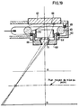
- Fig. 19 représente en coupe un mode de réalisation de la source auxiliaire.
- Fig. 20 représente schématiquement une variante de réalisation de la source auxiliaire.
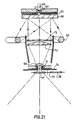
- Fig. 21 représente une autre variante de réalisation de la source auxiliaire.
- Figs. 1 and 2 illustrate the problems of variations in illumination in the image plane due to the inclination of the useful brush on the axis of the system.
- Figs. 3 to 6 illustrate the problems of variations in illumination in the image plane linked to those of the pupil of the projection objective.
- Fig. 7 shows the optical diagram of an apparatus according to the invention.
- Figs. 8 and 9 illustrate the possibilities of correcting the focusing of the apparatus according to the invention.
- Figs. 10 and 11 schematically represent two systems for correcting the chromatism of the thin lenses used in the apparatus of the invention.
- Fig. 12 shows in section an embodiment of a main source of the device according to the invention.
- Fig. 13 shows an alternative embodiment of the main source.
- Fig. 14 shows a section along line XIV-XIV of the device in FIG. 13.
- Fig. 15 shows in section another alternative embodiment of the main source.
- Fig. 16 shows in section the main source of FIG. 15 modified.
- Fig. 17 shows in section a preferred alternative embodiment of the main source.
- Fig. 18 schematically represents the arrangement of the auxiliary source of the apparatus according to the invention.
- Fig. 19 shows in section an embodiment of the auxiliary source.
- Fig. 20 schematically represents an alternative embodiment of the auxiliary source.
- Fig. 21 shows another alternative embodiment of the auxiliary source.
On va tout d'abord rappeler les problèmes photométriques qui se posent dans le cas des agrandisseurs photographiques dont l'appareil selon l'invention fait partie.We will first of all recall the photometric problems which arise in the case of photographic enlargers of which the apparatus according to the invention is a part.
En premier lieu, au niveau du dispositif d'éclairage, on forme l'image d'une source dans la pupille d'un objectif de projection au moyen d'un condenseur.First, at the level of the lighting device, the image of a source is formed in the pupil of a projection objective by means of a condenser.
Dans les dispositifs classiques, la distance entre l'original et le condenseur est faible et constante.In conventional devices, the distance between the original and the condenser is small and constant.
Le condenseur est en général composé de deux lentilles plan-convexes à faces sphériques ou asphériques. Dans quelques systèmes de projection, tels les « rétro-projecteurs •, ces lentilles sont remplacées par des lentilles moulées à échelons (type « FRESNEL"). Les performances de ces appareils sont cependant insuffisantes pour la réalisation de clichés photographiques.The condenser is generally composed of two plano-convex lenses with spherical or aspherical faces. In some projection systems, such as "overhead projectors", these lenses are replaced by molded stepped lenses ("FRESNEL" type). The performance of these devices is however insufficient for the production of photographic images.
Ainsi, le brevet US 3.834.813 mentionne l'emploi d'un condenseur constitué de deux lentilles à échelons travaillant pour leur foyer et l'infini dans un appareil de reproduction photographique.Thus, US Patent 3,834,813 mentions the use of a condenser consisting of two stepped lenses working for their focus and the infinite in a photographic reproduction apparatus.
Dans tous ces cas, lors des variations de grandissements, le réglage de l'image de la source dans la pupille de l'objectif s'effectue par déplacement de la source le long de l'axe du système avec ou sans changement de condenseur, celui-ci étant constamment placé contre l'original.In all these cases, during variations in magnifications, the adjustment of the image of the source in the pupil of the objective is carried out by displacement of the source along the axis of the system with or without change of condenser, the latter being constantly placed against the original.
Avec les dispositifs classiques d'éclairage, on observe des variations d'éclairement dans le plan image dues à l'inclinaison a du pinceau utile sur l'axe du système (figure 1).With conventional lighting devices, variations in lighting in the image plane are observed due to the inclination a of the useful brush on the axis of the system (FIG. 1).
Dans le cas d'une source circulaire plane diffu- sante (assimilable à la pupille d'un objectif de projection, uniformément éclairée), on pourrait compenser la diminution de l'éclairement due à l'inclinaison a à l'aide d'un écran correcteur 1 disposé à une certaine distance en dessous de la pupille 2 de l'objectif de projection, de manière à avoir dans le plan image 3 ou 3' un éclairement uniforme.In the case of a circular planar source diffu - health (similar to the pupil of a projection lens, uniformly illuminated), one could compensate for the decrease in illumination due to the inclination using a correction screen 1 arranged at a certain distance below the pupil 2 of the projection objective, so as to have in the
Cet écran correcteur 1 doit être calculé pour une distance donnée de la pupille 2 d'un objectif donné. Il en modifie les aberrations (aberrations sphériques, chromatisme, astigmatisme, distorsion) et apporte de la lumière parasite. De plus, il doit être réalisé avec une grande précision. En effet, il est obtenu par dépôt sous vide, afin de ne pas diffuser, et doit être déposé sur une lame plan-parallèle de qualité « optique et protégé par une lame identique étant donné la fragilité des dépôts de très faible absorption.This corrective screen 1 must be calculated for a given distance from the pupil 2 of a given objective. It modifies the aberrations (spherical aberrations, chromatism, astigmatism, distortion) and provides stray light. In addition, it must be performed with great precision. Indeed, it is obtained by vacuum deposition, in order not to diffuse, and must be deposited on a plane-parallel plate of “optical” quality and protected by an identical blade given the fragility of the deposits of very low absorption.
Du fait de l'épaisseur variable du dépôt absorbant depuis le centre jusqu'à la périphérie de l'écran et du fait des incidences obliques variables des rayons lumineux, le calcul, la réalisation de cet écran et son étalonnage en transmission sont difficiles, en sorte qu'il s'agit d'une solution coûteuse et peu envisageable. L'emploi d'un écran à dégradé radial est indiqué dans le brevet US 3.922.085.Due to the variable thickness of the absorbent deposit from the center to the periphery of the screen and due to the variable oblique incidences of the light rays, the calculation, the realization of this screen and its calibration in transmission are difficult, in so it is an expensive and hardly conceivable solution. The use of a radial gradient screen is indicated in US Patent 3,922,085.
On constate également dans ces appareils des variations d'éclairement dans le plan-image, liées à celles de la pupille de l'objectif de projection et dues à la mauvaise qualité de l'image d'une source lumineuse par surcroît non plane.In these devices, there are also variations in the illumination in the image plane, linked to those of the pupil of the projection objective and due to the poor quality of the image of a light source, moreover not planar.
Les figures 3 et 4 illustrent les variations d'éclairement (compte non tenu de l'affaiblissement en cos4 a) dans le cas d'une source plane de luminance uniforme et non uniforme respectivement, la source étant mise au point dans le plan de la pupille 4. Les ronds et ovales sur les figures 3 à 6 schématisent l'aspect de la pupille vu du centre ou du bord du champ.FIGS. 3 and 4 illustrate the variations in illumination (without taking into account the attenuation in cos 4 a) in the case of a planar source of uniform and non-uniform luminance respectively, the source being developed in the plane of pupil 4. The round and oval in Figures 3 to 6 show schematically the appearance of the pupil seen from the center or the edge of the field.
Dans le cas de la figure 3, on obtient au niveau de l'image un éclairement uniforme. Il en est de même dans le cas de la figure 4. En effet, si les pupilles sont couvertes non uniformément, on observe cependant du centre ou du bord du champ la même loi de répartition de luminance dans le plan de la pupille.In the case of FIG. 3, a uniform illumination is obtained at the level of the image. The same is true in the case of FIG. 4. In fact, if the pupils are covered non-uniformly, however, the same law of distribution of the luminance is observed from the center or from the edge of the field in the plane of the pupil.
Les figures 5 et 6 illustrent le cas d'une source mise au point en dehors du plan de la pupille avec respectivement une source de luminance uniforme et une source de luminance non uniforme.FIGS. 5 and 6 illustrate the case of a source developed outside the plane of the pupil with respectively a uniform luminance source and a non-uniform luminance source.
Dans le cas de la figure 5, on a un éclairement uniforme si l'image de la source est de diamètre nettement supérieur à celui de la pupille 4. Ceci présente l'inconvénient qu'on ne peut choisir entre un éclairage diffus et un éclairage dirigé de l'original. Dans ce cas, l'éclairage de l'original est du type diffus au centre du champ et du type dirigé au bord du champ.In the case of FIG. 5, there is a uniform illumination if the image of the source is of diameter much greater than that of pupil 4. This has the drawback that one cannot choose between diffuse lighting and lighting directed from the original. In this case, the lighting of the original is of the diffuse type in the center of the field and of the type directed at the edge of the field.
Dans le cas de la figure 6, il s'agit d'une source de luminance non uniforme et l'éclairement est également non uniforme.In the case of FIG. 6, it is a source of non-uniform luminance and the illumination is also non-uniform.
Dans le cas d'une source non plane, de forme hélicoïdale par exemple, l'image de la source n'est pas uniforme. Elle ne se forme pas dans un plan unique, celui de la pupille par exemple. On se trouve alors dans un cas analogue à celui illustré par la figure 6 (éclairement non uniforme).In the case of a non-planar source, of helical shape for example, the image of the source is not uniform. It does not form in a single plane, that of the pupil for example. We then find ourselves in a case analogous to that illustrated in FIG. 6 (non-uniform illumination).
En résumé, les conditions indispensables à l'obtention d'un éclairement uniforme dans le plan de reproduction sont les suivantes :In summary, the essential conditions for obtaining uniform illumination in the reproduction plan are as follows:
Elle doit être assimilable à une source plane, ayant une surface la plus grande possible afin de permettre l'éclairage du document original en lumière diffuse ; elle est placée perpendiculairement à l'axe optique du système et doit avoir de préférence une luminance uniforme et élevée, tout en rayonnant en chaque point suivant la loi de LAMBERT dans un angle solide a égal à celui du condenseur.It must be assimilated to a plane source, having the largest possible surface in order to allow the lighting of the original document in diffuse light; it is placed perpendicular to the optical axis of the system and must preferably have a uniform and high luminance, while radiating at each point according to LAMBERT's law in a solid angle equal to that of the condenser.
Il doit être de grandes dimensions pour couvrir les formats maximaux imposés et doit être bien corrigé des aberrations, en particulier sphériques et chromatiques, afin d'obtenir rigoureusement dans la pupille une excellente image de la source.It must be of large dimensions to cover the maximum formats imposed and must be well corrected for aberrations, in particular spherical and chromatic, in order to rigorously obtain in the pupil an excellent image of the source.
Il faut prévoir un système de réglage des dimensions de l'image de la source dans la pupille, afin de choisir à volonté un éclairage diffus, semi- dirigé ou dirigé, suivant les caractéristiques ou les défauts de l'original.It is necessary to provide a system for adjusting the dimensions of the image of the source in the pupil, in order to choose at will diffuse, semi-directed or directed lighting, according to the characteristics or defects of the original.
Cet écran doit être unique, si possible, quels que soient les objectifs et grandissements exigés et doit travailler en incidence normale pour tous les points du champ.This screen must be unique, if possible, whatever the objectives and magnifications required and must work in normal incidence for all points of the field.
Elle doit être prévue afin de produire un éclairement uniforme et réglable compte-tenu du terme cos4 α, quel que soit l'emplacement du plan de reproduction. Elle doit permettre de photométrer ce plan lorsqu'elle l'irradie simultanément avec la source principale, les deux sources pouvant être munies ou non d'écrans colorés.It must be planned in order to produce a uniform and adjustable illumination taking into account the term cos 4 α, whatever the location of the reproduction plane. It must make it possible to photometricize this plane when it irradiates it simultaneously with the main source, the two sources being able to be provided or not with colored screens.
La figure 7 représente le schéma optique d'un appareil conformément à l'invention, susceptible de satisfaire aux exigences rappelées ci-dessus.FIG. 7 represents the optical diagram of an apparatus according to the invention, capable of satisfying the requirements recalled above.
Cet appareil est constitué d'une source de lumière 10, d'un verre dépoli 11 sur sa face extérieure plane pour obtenir une source de luminance plus uniforme que la source elle-même, et d'un diaphragme 12 au contact du dépoli. Ce diaphragme 12 est constitué par un disque rotatif autour d'un axe 13 parallèle à l'axe optique 14 du système. Sur la figure 7, on a représenté deux trous 15 et 16 dans le diaphragme 12. Le trou 16 est dans l'axe 14 du système et a un diamètre sensiblement supérieur à celui du trou 15.This device consists of a light source 10, a frosted glass 11 on its flat outer face to obtain a more uniform luminance source than the source itself, and a
Le diaphragme 12 est interposé entre le verre dépoli 11 et un verre 17 destiné à arrêter les infrarouges.The
Derrière le verre 17 sont disposés les écrans colorés 18 montés sur un disque rotatif 19.Behind the glass 17 are arranged the colored screens 18 mounted on a
Le condenseur de l'appareil est constitué de deux lentilles à échelons 20 et 21 travaillant pour leur foyer et l'infini et entre lesquelles est disposé un écran 22 correcteur du terme cos4 a, travaillant perpendiculairement à sa surface. Ces lentilles sont utilisées de préférence au grandissement 1 et sont alors identiques en vue de limiter les risques de moirage.The condenser of the apparatus consists of two stepped
Le condenseur forme l'image de la source dans le plan des pupilles d'objectifs 23 de focales diverses.The condenser forms the image of the source in the plane of the
On a représenté en 24 et 24' deux positions différentes du document à reproduire et en 25 et 25' les deux positions correspondantes du plan de reproduction.There are shown at 24 and 24 'two different positions of the document to be reproduced and at 25 and 25' the two corresponding positions of the reproduction plane.
Le trou 15 du diaphragme 12 a un diamètre inférieur aux pupilles des objectifs 23 et correspond à un éclairage dirigé, alors que le trou 16, qui est de diamètre supérieur, correspond à un éclairage diffus.The
Les flèches 26 indiquent les sens de déplacement du document 24 selon le format. En effet, conformément à l'invention, c'est le document 24 qui se déplace par rapport à l'ensemble formé par la source lumineuse, le condenseur et les objectifs.The
L'écran 22 correcteur du terme cos4 α peut être constitué de différentes manières. Il peut être formé par un dépôt de couches minces absorbantes, par le dépôt d'une couche de gélatine absorbante plus ou moins intensément selon que l'on se trouve plus ou moins proche du centre de l'écran, ou par un film photographique non tramé ou bien tramé avec une trame aléatoire, exposé puis développé. La qualité optique de cet écran a peu d'importance étant donné qu'il est placé avant l'objectif et l'original.The
Dans le cas de la réalisation de cet écran 22 à l'aide de couches absorbantes, du fait que cet écran est disposé entre les deux lentilles 20 et 21 dans le faisceau parallèle, le dépôt des couches et l'étalonnage de l'écran en transmission sont nettement plus faciles à calculer et à mesurer que dans le cas de l'écran de la figure 2. Le dépôt peut être effectué sur une lame sans qualité « optique ».In the case of the production of this
Les figures 8 et 9 illustrent les possibilités de correction de la mise au point de l'appareil selon l'invention en fonction des différents formats. Sur ces figures, on a représenté en 30 le plan de travail du porte-document et en 31 le sol sur lequel repose l'appareil. Selon le format du document (32 ou 32'), on déplace d'un seul bloc l'ensemble formé par la source schématisée en 33, le condenseur 34 et l'objectif 35.Figures 8 and 9 illustrate the possibilities of correcting the focusing of the apparatus according to the invention according to the different formats. In these figures, there is shown at 30 the work surface of the document holder and at 31 the ground on which the apparatus rests. Depending on the format of the document (32 or 32 '), the assembly formed by the source shown diagrammatically at 33, the
La conjugaison source-pupille de l'objectif est réalisée à la fabrication, et le déplacement de l'ensemble source-condenseur-objectif dans le cas du porte-document fixe peut être réalisé manuellement ou automatiquement.The source-pupil conjugation of the objective is carried out during manufacture, and the displacement of the source-condenser-objective assembly in the case of the fixed document holder can be carried out manually or automatically.
Les figures 10 et 11 représentent schématiquement deux systèmes de correction du chromatisme des lentilles 20 et 21. Ces corrections sont indispensables dans le cas de l'éclairage en lumière dirigée, mais ne le sont pas nécessairement dans le cas de l'éclairage en lumière diffuse. Dans le cas de la figure 10, ce système de correction du chromatisme est constitué par un écran coloré 40 enchâssé entre deux verres plan-parallèles épais 41 disposés derrière le diaphragme 12, la sur-correction des verres 41 compensant la sous-correction chromatique des lentilles 20 et 21.FIGS. 10 and 11 schematically represent two systems for correcting the chromaticism of
Lors de l'utilisation, par exemple, de la lumière rouge, la mise au point est faite directement sur le diaphragme 12 (0 rouge avec l'écran 18). Dans le cas de la lumière bleue, la mise au point est effectuée sur l'image 0' du diaphragme au travers de l'ensemble correcteur 40-41.When using, for example, red light, the focus is made directly on the diaphragm 12 (0 red with the screen 18). In the case of blue light, the focusing is carried out on the image 0 'of the diaphragm through the corrector assembly 40-41.
Dans le cas de la figure 11, le système de correction est constitué d'un verre plan-parallèle 42 de dispersion et d'épaisseur convenables, un écran coloré 18 pouvant venir se placer devant le verre correcteur 42. Celui-ci est chargé de corriger la sous-correction des lentilles 20 et 21.In the case of FIG. 11, the correction system consists of a plane-
Sur la figure 11, les plans 43 et 44 sont les images rouge et bleue du diaphragme 12 au travers du verre correcteur 42 et correspondent aux foyers des lentilles 20 et 21.In FIG. 11, the
La source de lumière est une source XENON pulsée standard de forme hélicoïdale 50. La source 50 est entourée d'un tronc de cône réfléchissant intérieurement 51, cependant que dans l'axe des spires de la source est disposé un cône réfléchissant extérieurement 52.The light source is a standard pulsed XENON source of
Le dispositif est complété par une lentille divergente dépolie 53 et un diaphragme 54.The device is completed by a frosted
La lentille divergente 53 a pour but de diminuer l'épaisseur apparente de la forme hélicoïdale 50 et de rapprocher son image du dépoli afin de simuler le plus possible une source plane, cependant que le tronc de cône 51 et le cône 52 ont pour but d'augmenter la luminance et son uniformité à la surface dépolie de la lentille 53.The purpose of the
Les figures 13 et 14 illustrent une variante de réalisation de la source principale.Figures 13 and 14 illustrate an alternative embodiment of the main source.
Suivant cette variante, on utilise une source XENON pulsée 50' dont l'enroulement du tube suit une autre disposition. Les spires sont allongées, parallèles entre elles et disposées en quinconce suivant une coupe transversale (figure 14). Le système est complété par un miroir 55 à section en forme d'auge, par un verre dépoli 56 et un diaphragme 57. Cette variante permet d'obtenir une plus grande uniformité, une plus grande luminosité du verre dépoli ainsi qu'un refroidissement par air plus aisé.According to this variant, a
La figure 15 illustre une autre forme de réalisation de la source principale.Figure 15 illustrates another embodiment of the main source.
On dispose à cet effet d'une source XENON pulsée standard de forme hélicoïdale 80 disposée derrière un verre dépoli 81. Pour améliorer l'éclairement au niveau du dépoli 81, on dispose derrière la source un miroir sphérique concave 82 réfléchissant intérieurement de façon à obtenir un système de révolution, c'est-à-dire que l'axe XX' du tube hélicoïdal constituant la source XENON est confondu avec l'axe du système optique et celui du miroir sphérique dont le centre C se trouve à l'intérieur dudit tube hélicoïdal.For this purpose, there is a standard pulsed XENON source of
Avec une source principale du genre repré- senté à la figure 15, il peut encore exister au centre du verre dépoli 81 une zone sombre.With a main source of gender repre - sented in Figure 15, there may still be the frosted glass of the center 81 a dark area.
Cette zone peut être atténuée en utilisant le montage représenté sur la figure 16. On dispose comme pour le montage de la figure 15 d'une source XENON pulsée de forme hélicoïdale 80, d'un miroir sphérique 82 de centre C et d'un verre dépoli 81. Mais, dans ce cas, on décentre légèrement le miroir 82, ce qui décale latéralement l'image de la source mais supprime la symétrie de révolution. Pour rétablir cette symétrie, on fait tourner le miroir 82 autour de l'axe XX' du tube XENON tel qu'indiqué par la flèche à l'aide d'un moteur 83 ou de tout dispositif similaire. On obtient ainsi une meilleure uniformité d'éclairement du verre dépoli 81. Une telle construction est plus difficile à réaliser mécaniquement. En outre, l'éclairement obtenu n'est pas de révolution à un instant donné.This area can be attenuated by using the assembly shown in Figure 16. As with the assembly in Figure 15, there is a XENON pulsed source of
Le montage de source principale de la figure 17 permet d'éviter une telle rotation du miroir sphérique. On remplace à cet effet le miroir sphérique décentré mobile de la figure 16 par un miroir torique fixe concave 84 réfléchissant intérieurement de manière à obtenir un système de révolution. Les centres C, et C2 respectivement des parties de tore 85 et 86 ont été choisis légèrement excentrés par rapport à l'axe XX' du tube XENON de forme hélicoïdale standard 87 et sont situés de telle manière que les images fournies par les diverses régions du miroir se reforment légèrement agrandies de part et d'autre du plan du verre dépoli 81 et de l'axe XX'.The main source arrangement in FIG. 17 makes it possible to avoid such rotation of the spherical mirror. For this purpose, the movable off-center spherical mirror of FIG. 16 is replaced by a concave fixed
On peut encore améliorer ce montage de source principale avec un miroir torique en y prévoyant un second miroir M, sphérique et concave, réfléchissant intérieurement. Le centre C3 de ce second miroir se trouve sur l'axe XX' du tube XENON. Ce miroir M est placé face au miroir torique 84 et entoure la source 87.We can further improve this main source assembly with a toroidal mirror by providing a second mirror M, spherical and concave, reflecting internally. The center C 3 of this second mirror is on the axis XX 'of the XENON tube. This mirror M is placed opposite the
La présence du miroir M permet une augmentation supplémentaire de l'éclairement de la « source plane par récupération de faisceaux lumineux situés hors du champ du miroir torique. Ce miroir sphérique M présente deux autres avantages : d'une part il facilite la circulation d'air autour du tube de forme hélicoïdale, donc son refroidissement, et, d'autre part, il intercepte des faisceaux qui, sans ledit miroir, fourniraient de la lumière parasite autour de l'appareil.The presence of the mirror M allows a further increase in the illumination of the “flat source by recovery of light beams located outside the field of the toric mirror. This spherical mirror M has two other advantages: on the one hand it facilitates the circulation of air around the helical tube, therefore its cooling, and, on the other hand, it intercepts beams which, without said mirror, would provide stray light around the device.
La figure 18 montre l'emplacement d'une source auxiliaire 60 dans l'appareil selon l'invention en vue d'éclairer uniformément le plan de reproduction 61.FIG. 18 shows the location of an
La figure 19 représente en coupe un mode de réalisation de cette source auxiliaire.Figure 19 shows in section an embodiment of this auxiliary source.
Elle comprend un boîtier 62 dans lequel est enfermée une source fluorescente annulaire 63 maintenue en place par des joints de centrage 64 et 65.It comprises a
Dans le fond du boîtier 62 est monté de manière amovible un écran blanc diffusant 66 plan ou sphérique. L'écran 66 est solidaire d'un bouchon 67 vissé dans le boîtier 62, ce qui permet de régler la distance entre l'écran 66 et la source fluorescente annulaire 63, l'écran 66 étant disposé dans l'axe de cette source. Dans te boîtier, à l'opposé de l'écran 66, est disposé, dans un barillet 68 vissé dans le boîtier 62, un objectif constitué par un ménisque 69.In the bottom of the
Entre la source 63 et l'écran 66 est interposé un écran tubulaire 70 réglable suivant l'axe du système optique de manière à modifier la répartition des éclairements sur le plan diffusant.Between the
Du côté du ménisque 69 opposé à l'écran 66, est prévu, sur les bords de ce ménisque, un tronc de cône réfléchissant 71 destiné à supprimer l'effet d'oeil de chat au niveau de la pupille de sortie du ménisque 69.On the side of the
Sur la figure 19, on a représenté en A et B les plans extrêmes de reproduction et en tiretés le plan moyen de mise au point.In Figure 19, there is shown in A and B the extreme reproduction planes and dashed the average plane of development.
Suivant une variante de ce dispositif représentée à la figure 20, l'écran tubulaire 70 (figure 19) qui modifie la répartition lumineuse dans le plan de l'écran diffusant 66, peut être remplacé par une lentille de champ 72 et un écran correcteur 73 du terme COS 4 a. Le foyer de la lentille de champ 72 est conjugué de l'image de la pupille avant (petite base du tronc de cône 71) du ménisque 69. L'écran correcteur 73 est placé en faisceau parallèle contre la lentille de champ 72 entre celle-ci et l'écran diffusant. L'écran diffusant 66 est situé convenablement par rapport à la source annulaire 63 afin que son éclairement soit uniforme. La pupille avant de l'objectif peut être complétée par un diaphragme réglable 74 et par un disque 75 porteur de verres colorés 76-77.According to a variant of this device shown in Figure 20, the tubular screen 70 (Figure 19) which changes the light distribution in the plane of the diffusing
Ces deux derniers dispositifs peuvent être prévus dans le mode de réalisation de la figure 19.These last two devices can be provided in the embodiment of FIG. 19.
Selon une variante du dispositif de la figure 20, l'écran blanc diffusant 66 peut être remplacé par un disque 90 transparent, translucide ou opalin (figure 21) en verre synthétique, tel qu'un poly- méthacrylate de méthyle, par exemple celui mis sur le marché sous la dénomination « Altuglas par la Société Altulor (France). A l'arrière du disque 90 est disposé un écran opaque blanc 91 portant la reproduction d'un dégradé radial destiné à modifier la répartition de la luminance du disque 90. Cet écran 91 est obtenu par photographie ou par tout autre procédé approprié. Il est prévu en outre dans ce montage de source auxiliaire une cellule photo-électrique 93 placée derrière une ouverture 92 ménagée au centre de cet écran dégradé. Cette cellule sert à contrôler et à asservir l'intensité du tube lumineux 63. Par ailleurs, tous les autres éléments du montage de source auxiliaire de la figure 21 sont identiques à ceux de la figure 20. Ce dernier dispositif peut être prévu dans le mode de réalisation de la figure 19.According to a variant of the device in FIG. 20, the
L'appareil objet de la présente invention permet d'obtenir un certain nombre d'avantages sur le plan pratique. Il permet notamment de réduire les temps de pose jusqu'à 10 fois par rapport aux appareils de la technique antérieure. Il permet en outre d'obtenir de très bonnes reproductions avec des sources 4 à 5 fois moins puissantes que celles de l'art connu, par exemple avec des sources de 5 KW. Il faut ajouter, comme déjà mentionné ci-dessus, qu'on peut, grâce à l'appareil selon l'invention, augmenter les formats maximaux utilisables pour atteindre par exemple un format de 20 x 25 cm pour l'original et 50 x 65 cm pour la reproduction. L'appareil selon l'invention trouve une application dans le domaine industriel : pour effectuer une reproduction, seule la source principale est obligatoire (figure 7), mais, pour faire de la photo-gravure, il est indispensable de prévoir en outre une source auxiliaire (figures 18 à 21).The apparatus which is the subject of the present invention makes it possible to obtain a certain number of advantages from the practical point of view. It allows in particular to reduce the exposure times up to 10 times compared to the devices of the prior art. It also makes it possible to obtain very good reproductions with sources 4 to 5 times less powerful than those of the known art, for example with sources of 5 KW. It should be added, as already mentioned above, that it is possible, thanks to the device according to the invention, to increase the maximum usable formats to reach for example a format of 20 x 25 cm for the original. and 50 x 65 cm for reproduction. The apparatus according to the invention finds an application in the industrial field: to carry out a reproduction, only the main source is obligatory (FIG. 7), but, to make photo-engraving, it is essential to provide in addition a source auxiliary (Figures 18 to 21).
Claims (14)
Applications Claiming Priority (2)
| Application Number | Priority Date | Filing Date | Title |
|---|---|---|---|
| FR7716947A FR2393338A1 (en) | 1977-06-03 | 1977-06-03 | IMPROVEMENTS TO EQUIPMENT FOR PHOTOGRAPHIC REPRODUCTION OF TRANSPARENT DOCUMENTS |
| FR7716947 | 1977-06-03 |
Publications (2)
| Publication Number | Publication Date |
|---|---|
| EP0000450A1 EP0000450A1 (en) | 1979-01-24 |
| EP0000450B1 true EP0000450B1 (en) | 1981-03-25 |
Family
ID=9191622
Family Applications (1)
| Application Number | Title | Priority Date | Filing Date |
|---|---|---|---|
| EP78400010A Expired EP0000450B1 (en) | 1977-06-03 | 1978-06-01 | Photographic reproduction apparatus for transparent documents, especially of the photographic enlarger type |
Country Status (6)
| Country | Link |
|---|---|
| US (1) | US4229097A (en) |
| EP (1) | EP0000450B1 (en) |
| JP (1) | JPS5417724A (en) |
| DE (1) | DE2860556D1 (en) |
| FR (1) | FR2393338A1 (en) |
| IT (1) | IT1095283B (en) |
Families Citing this family (10)
| Publication number | Priority date | Publication date | Assignee | Title |
|---|---|---|---|---|
| US4298274A (en) * | 1980-01-07 | 1981-11-03 | Rees James D | Variable density filter for a multi-magnification copying device |
| EP0033185B1 (en) * | 1980-01-07 | 1984-05-23 | Xerox Corporation | Method and apparatus for compensating for illumination defects in an optical system |
| US4298275A (en) * | 1980-01-07 | 1981-11-03 | Xerox Corporation | Radially varying transmission filter for wide angle copying device |
| US4445774A (en) * | 1982-04-30 | 1984-05-01 | Xerox Corporation | Document imaging system with improved exposure uniformity at image plane |
| US5014086A (en) * | 1989-03-31 | 1991-05-07 | E. I. Du Pont De Nemours And Company | Adjustable dot gain simulation for color proofing |
| DE59209275D1 (en) * | 1992-09-09 | 1998-05-14 | Gretag Imaging Ag | Illumination system for photographic copiers |
| US5461456A (en) * | 1992-11-24 | 1995-10-24 | General Signal Corporation | Spatial uniformity varier for microlithographic illuminator |
| DE10046353A1 (en) * | 2000-09-19 | 2002-04-11 | Agfa Gevaert Ag | Illumination device for illuminating a transparent image template |
| DE102004059951A1 (en) * | 2004-08-17 | 2006-02-23 | Giesecke & Devrient Gmbh | Device for examining documents |
| EP2042521A1 (en) | 2006-03-29 | 2009-04-01 | Nippon Shokubai Co., Ltd. | Method of producing polyacrylic acid (salt) water-absorbent resin |
Family Cites Families (5)
| Publication number | Priority date | Publication date | Assignee | Title |
|---|---|---|---|---|
| FR1021016A (en) * | 1950-06-27 | 1953-02-13 | Contrast-corrected enlarger | |
| DE1225041B (en) * | 1964-07-16 | 1966-09-15 | Multiblitz Geraete Dr Ing D A | Device for photographic exposure, preferably for enlarging devices |
| US3834813A (en) * | 1970-10-15 | 1974-09-10 | Haggar Co | Diazo printing system |
| US3922085A (en) * | 1974-08-22 | 1975-11-25 | Tamarack Scient Co Inc | Illuminator for microphotography |
| CH597618A5 (en) * | 1975-12-02 | 1978-04-14 | Zelacolor Syst |
-
1977
- 1977-06-03 FR FR7716947A patent/FR2393338A1/en active Granted
-
1978
- 1978-05-31 US US05/911,073 patent/US4229097A/en not_active Expired - Lifetime
- 1978-05-31 IT IT24086/78A patent/IT1095283B/en active
- 1978-06-01 DE DE7878400010T patent/DE2860556D1/en not_active Expired
- 1978-06-01 EP EP78400010A patent/EP0000450B1/en not_active Expired
- 1978-06-02 JP JP6584878A patent/JPS5417724A/en active Pending
Also Published As
| Publication number | Publication date |
|---|---|
| EP0000450A1 (en) | 1979-01-24 |
| JPS5417724A (en) | 1979-02-09 |
| FR2393338B1 (en) | 1980-05-23 |
| IT1095283B (en) | 1985-08-10 |
| DE2860556D1 (en) | 1981-04-16 |
| US4229097A (en) | 1980-10-21 |
| IT7824086A0 (en) | 1978-05-31 |
| FR2393338A1 (en) | 1978-12-29 |
Similar Documents
| Publication | Publication Date | Title |
|---|---|---|
| CA1260297A (en) | Lighting device, particularly a spotlight with simultaneous setting of all its parameters | |
| US7929220B2 (en) | Adjustable apodized lens aperture | |
| EP0014609B1 (en) | Large screen visualisation apparatus | |
| EP0000450B1 (en) | Photographic reproduction apparatus for transparent documents, especially of the photographic enlarger type | |
| FR2805351A1 (en) | OPTICAL LIGHTING SYSTEM AND PROJECTION TYPE DISPLAY DEVICE USING THE SYSTEM | |
| FR2487993A1 (en) | ARTIFICIAL LIGHTING ASSEMBLY FOR PHOTOGRAPHIC APPARATUS AND REFLECTOR FOR THIS ASSEMBLY | |
| EP2860582B1 (en) | System for acquiring photographic portraits | |
| EP1477019B1 (en) | Method for transferring a digital image so as to visually restore said digital image, and device for carrying out said method | |
| EP0001951B1 (en) | Projection apparatus permitting the recording of the projected image of an object | |
| FR2667954A1 (en) | Compact device for colouring light beams and corresponding objective | |
| EP0058186B1 (en) | Photographic enlarger with pinpoint light source | |
| WO2022128061A1 (en) | Uniform lighting box for photographic or camera imaging | |
| FR2693561A1 (en) | Source of polarised light for overhead projector - uses two confocal lenses and small light source emitting polarised beam and number of slides fixed at Brewster angle to deflect beam which is returned by mirror | |
| BE444835A (en) | ||
| FR2472207A1 (en) | METHOD FOR REPRODUCING IMAGES FROM A TRANSPARENT IMAGE MEDIUM ON A PHOTOSENSITIVE MEDIUM AND DEVICE FOR CARRYING OUT SAID METHOD | |
| FR2760856A1 (en) | LIGHTING DEVICE | |
| CA3070924A1 (en) | Diffractive illumination device with increased diffraction angle | |
| BE489206A (en) | ||
| FR2580823A1 (en) | Device for projecting backgrounds, especially for producing photographs | |
| CH279948A (en) | Cinematographic projector. | |
| BE428761A (en) | ||
| BE486383A (en) | ||
| BE520500A (en) | ||
| BE377406A (en) | ||
| CH159689A (en) | Apparatus for reproducing photographic images on embossed film. |
Legal Events
| Date | Code | Title | Description |
|---|---|---|---|
| PUAI | Public reference made under article 153(3) epc to a published international application that has entered the european phase |
Free format text: ORIGINAL CODE: 0009012 |
|
| AK | Designated contracting states |
Designated state(s): BE CH DE FR GB LU NL SE |
|
| 17P | Request for examination filed | ||
| DET | De: translation of patent claims | ||
| GRAA | (expected) grant |
Free format text: ORIGINAL CODE: 0009210 |
|
| AK | Designated contracting states |
Designated state(s): BE CH DE FR GB LU NL SE |
|
| REF | Corresponds to: |
Ref document number: 2860556 Country of ref document: DE Date of ref document: 19810416 |
|
| PG25 | Lapsed in a contracting state [announced via postgrant information from national office to epo] |
Ref country code: LU Free format text: LAPSE BECAUSE OF NON-PAYMENT OF DUE FEES Effective date: 19810630 |
|
| PGFP | Annual fee paid to national office [announced via postgrant information from national office to epo] |
Ref country code: FR Payment date: 19830628 Year of fee payment: 6 |
|
| PGFP | Annual fee paid to national office [announced via postgrant information from national office to epo] |
Ref country code: LU Payment date: 19831019 Year of fee payment: 6 |
|
| PGFP | Annual fee paid to national office [announced via postgrant information from national office to epo] |
Ref country code: NL Payment date: 19831024 Year of fee payment: 6 |
|
| PGFP | Annual fee paid to national office [announced via postgrant information from national office to epo] |
Ref country code: DE Payment date: 19831026 Year of fee payment: 6 |
|
| PGFP | Annual fee paid to national office [announced via postgrant information from national office to epo] |
Ref country code: SE Payment date: 19831031 Year of fee payment: 6 Ref country code: CH Payment date: 19831031 Year of fee payment: 6 |
|
| PGFP | Annual fee paid to national office [announced via postgrant information from national office to epo] |
Ref country code: BE Payment date: 19831130 Year of fee payment: 6 |
|
| PG25 | Lapsed in a contracting state [announced via postgrant information from national office to epo] |
Ref country code: SE Effective date: 19840602 |
|
| PG25 | Lapsed in a contracting state [announced via postgrant information from national office to epo] |
Ref country code: CH Effective date: 19840630 Ref country code: BE Effective date: 19840630 |
|
| BERE | Be: lapsed |
Owner name: ANVAR AGENCE NATIONALE DE VALORISATION DE LA RECH Effective date: 19840601 |
|
| PG25 | Lapsed in a contracting state [announced via postgrant information from national office to epo] |
Ref country code: NL Effective date: 19850101 |
|
| GBPC | Gb: european patent ceased through non-payment of renewal fee | ||
| NLV4 | Nl: lapsed or anulled due to non-payment of the annual fee | ||
| PG25 | Lapsed in a contracting state [announced via postgrant information from national office to epo] |
Ref country code: FR Free format text: LAPSE BECAUSE OF NON-PAYMENT OF DUE FEES Effective date: 19850228 |
|
| REG | Reference to a national code |
Ref country code: CH Ref legal event code: PL |
|
| PG25 | Lapsed in a contracting state [announced via postgrant information from national office to epo] |
Ref country code: DE Effective date: 19850301 |
|
| REG | Reference to a national code |
Ref country code: FR Ref legal event code: ST |
|
| PG25 | Lapsed in a contracting state [announced via postgrant information from national office to epo] |
Ref country code: GB Free format text: LAPSE BECAUSE OF NON-PAYMENT OF DUE FEES Effective date: 19881117 |
|
| EUG | Se: european patent has lapsed |
Ref document number: 78400010.1 Effective date: 19850612 |
|
| PLBE | No opposition filed within time limit |
Free format text: ORIGINAL CODE: 0009261 |
|
| STAA | Information on the status of an ep patent application or granted ep patent |
Free format text: STATUS: NO OPPOSITION FILED WITHIN TIME LIMIT |