DE69835521T2 - DEVICE AND METHOD FOR IMPLEMENTING AND RECOVERING INFORMATION IN ANALOG SIGNALS USING THE DISTRIBUTED SIGNAL FEATURES - Google Patents

DEVICE AND METHOD FOR IMPLEMENTING AND RECOVERING INFORMATION IN ANALOG SIGNALS USING THE DISTRIBUTED SIGNAL FEATURES Download PDF

Info

Publication number
DE69835521T2
DE69835521T2 DE69835521T DE69835521T DE69835521T2 DE 69835521 T2 DE69835521 T2 DE 69835521T2 DE 69835521 T DE69835521 T DE 69835521T DE 69835521 T DE69835521 T DE 69835521T DE 69835521 T2 DE69835521 T2 DE 69835521T2
Authority
DE
Germany
Prior art keywords
signal
cover
value
masking
calculating
Prior art date
Legal status (The legal status is an assumption and is not a legal conclusion. Google has not performed a legal analysis and makes no representation as to the accuracy of the status listed.)
Expired - Lifetime
Application number
DE69835521T
Other languages
German (de)
Other versions
DE69835521D1 (en
Inventor
Rade Wilmington PETROVIC
Kanaan Woburn JEMILI
M. Joseph 32 Fairmont Avenue Cambridge WINOGRAD
Eric Somerville METOIS
Current Assignee (The listed assignees may be inaccurate. Google has not performed a legal analysis and makes no representation or warranty as to the accuracy of the list.)
VERANCE CORP SAN DIEGO
Verance Corp
Original Assignee
VERANCE CORP SAN DIEGO
Verance Corp
Priority date (The priority date is an assumption and is not a legal conclusion. Google has not performed a legal analysis and makes no representation as to the accuracy of the date listed.)
Filing date
Publication date
Priority claimed from US08/858,562 external-priority patent/US5940135A/en
Application filed by VERANCE CORP SAN DIEGO, Verance Corp filed Critical VERANCE CORP SAN DIEGO
Application granted granted Critical
Publication of DE69835521D1 publication Critical patent/DE69835521D1/en
Publication of DE69835521T2 publication Critical patent/DE69835521T2/en
Anticipated expiration legal-status Critical
Expired - Lifetime legal-status Critical Current

Links

Classifications

    • HELECTRICITY
    • H04ELECTRIC COMMUNICATION TECHNIQUE
    • H04HBROADCAST COMMUNICATION
    • H04H20/00Arrangements for broadcast or for distribution combined with broadcast
    • H04H20/28Arrangements for simultaneous broadcast of plural pieces of information
    • H04H20/30Arrangements for simultaneous broadcast of plural pieces of information by a single channel
    • H04H20/31Arrangements for simultaneous broadcast of plural pieces of information by a single channel using in-band signals, e.g. subsonic or cue signal
    • GPHYSICS
    • G06COMPUTING; CALCULATING OR COUNTING
    • G06TIMAGE DATA PROCESSING OR GENERATION, IN GENERAL
    • G06T1/00General purpose image data processing
    • G06T1/0021Image watermarking
    • G06T1/0028Adaptive watermarking, e.g. Human Visual System [HVS]-based watermarking
    • GPHYSICS
    • G06COMPUTING; CALCULATING OR COUNTING
    • G06TIMAGE DATA PROCESSING OR GENERATION, IN GENERAL
    • G06T2201/00General purpose image data processing
    • G06T2201/005Image watermarking
    • G06T2201/0052Embedding of the watermark in the frequency domain

Landscapes

  • Engineering & Computer Science (AREA)
  • Signal Processing (AREA)
  • Physics & Mathematics (AREA)
  • General Physics & Mathematics (AREA)
  • Theoretical Computer Science (AREA)
  • Compression Or Coding Systems Of Tv Signals (AREA)
  • Editing Of Facsimile Originals (AREA)
  • Radio Relay Systems (AREA)
  • Signal Processing For Digital Recording And Reproducing (AREA)

Abstract

Apparatus and methods are provided for embedding or embedding digital data into an analog host or cover signal. A distributed signal feature of the cover signal in a particular domain (time, frequency or space) is calculated and compared with a set of predefined quantization values corresponding to an information symbol to be encoded. The amount of change required to modify the signal feature to the determined target quantization value is calculated and the cover signal is modified accordingly to so change the feature value over a predefined interval. Information symbols are extracted by the opposite process. In one embodiment, the predefined value is a short term autocorrelation value of the cover signal.

Description

HINTERGRUND DER ERFINDUNGBACKGROUND OF THE INVENTION

Gebiet der ErfindungField of the invention

Diese Erfindung betrifft Vorrichtungen und Verfahren zum Codieren und Decodieren von Informationen in Analogsignalen, wie bspw. in Audio-, Video- und Datensignalen, die entweder durch Funk- bzw. Radiowellenübertragung oder drahtgestützte Übertragung übermittelt werden oder in einem Aufzeichnungsmedium, wie bspw. in einer optischen oder magnetischen Platte, einem Magnetband oder einem Festkörperspeicher, gespeichert werden.These The invention relates to devices and methods for coding and Decoding of information in analog signals, such as in audio, Video and data signals transmitted either by radio or radio wave transmission or wire-based transmission or in a recording medium, such as in an optical or magnetic disk, a magnetic tape or a solid state memory, get saved.

Hintergrund und Beschreibung des Stands der Technikbackground and Description of the Related Art

Ein Gebiet, das für bestimmte Ausführungsformen der vorliegenden Erfindung von besonderem Interesse ist, betrifft den Markt für Musikaufzeichnungen. Gegenwärtig hört eine große Anzahl von Personen Musikaufzeichnungen im Radio oder im Fernsehen. Sie hören häufig eine Aufzeichnung, die sie ausreichend mögen, um sie zu kaufen, sie kennen jedoch den Namen des Lieds, des ihn aufführenden Künstlers oder die Aufzeichnung, das Band oder das CD-Album, zu dem es gehört, nicht. Daher ist die Anzahl der Aufzeichnungen, die Personen kaufen, kleiner als sie es andernfalls wäre, wenn es für Personen einen einfachen Weg gäbe, die Aufzeichnungen, die sie im Radio oder Fernsehen hören und die sie kaufen möchten, zu identifizieren.One Area that for certain embodiments of the present invention of particular interest the market for Music recordings. Currently hear one size Number of people Music recordings on the radio or on television. You hear often a record they like enough to buy them but know the name of the song, the artist performing it or the recording, not the band or the CD album to which it belongs. Therefore, the number is the records that people buy smaller than they otherwise do would be if it for Give people an easy way, the Records that they hear on the radio or television and you want to buy to identify.

Ein weiterer für bestimmte Ausführungsformen der Erfindung interessanter Bereich ist die Kopierkontrolle. Es gibt gegenwärtig einen großen Markt für Audiosoftwareprodukte, wie Musikaufzeichnungen. Eines der auf diesem Markt auftretenden Probleme besteht darin, dass es leicht möglich ist, diese Produkte zu kopieren, ohne jene, die sie erzeugen, zu bezahlen. Dieses Problem wird mit dem Aufkommen von Aufzeichnungstechniken, wie Digital Audio Tape (DAT), die Kopien sehr hoher Qualität ermöglichen, besonders lästig. Es wäre demgemäß wünschenswert, ein Schema zu entwickeln, das das unberechtigte Kopieren von Audioaufzeichnungen unter Einschluss des unberechtigten Kopierens von über Luftwellen ausgestrahlten Audioprodukten, verhindert. Es ist auch wünschenswert, dass die Erzwingung des Urheberrechts in der Lage ist, in Programmmaterial, wie Audio- oder Videosignale, digitale Urheberrechtsinformationen einzufügen, die den Inhaber des Urheberrechts identifizieren, wobei diese Informationen durch geeignete Vorrichtungen erkannt werden können, um den Eigentümer des Urheberrechts des Programms zu identifizieren, während sie für den Hörer oder Betrachter nicht wahrnehmbar bleiben.One more for certain embodiments interesting area of the invention is the copy control. It currently available a big Market for Audio software products, such as music recordings. One of this on this Market problems is that it is easily possible to copy these products without paying those who produce them. This problem arises with the advent of recording techniques, like Digital Audio Tape (DAT), which enables very high quality copies especially annoying. It would therefore be desirable to develop a scheme that allows the unauthorized copying of audio recordings including unauthorized copying of air waves emitted audio products. It is also desirable that the enforcement of copyright is capable of such as audio or video signals, digital copyright information insert, which identify the copyright owner, this information can be detected by appropriate devices to the owner of the Identify copyright of the program while not perceptible to the listener or viewer stay.

Es sind verschiedene Verfahren aus dem Stand der Technik zum Codieren zusätzlicher Informationen auf ein Quellensignal bekannt. Beispielsweise ist es bekannt, ein Signal einer Impulsbreitenmodulation zu unterziehen, um ein ge meinsames oder codiertes Signal bereitzustellen, das mindestens zwei Informationsabschnitte oder andere nützliche Abschnitte trägt. Im Yang erteilten US-Patent 4 497 060 (1985) werden binäre Daten als ein Signal mit zwei verschiedenen Impulsbreiten übertragen, um eine logische "0" und "1" darzustellen (beispielsweise sind die Impulsbreitendauern für eine "1" zweimal so groß wie die Dauer für eine "0"). Diese Entsprechung ermöglicht auch das Festlegen eines Taktsignals.It are various prior art methods of encoding additional Information on a source signal known. For example it is known to subject a signal to pulse width modulation, to provide a common or coded signal that is at least carries two pieces of information or other useful sections. In the yang U.S. Patent 4,497,060 (1985), binary data is included as a signal transmit two different pulse widths to represent a logical "0" and "1" (For example, the pulse width durations for a "1" are twice as big as the duration for a "0"). This correspondence allows also setting a clock signal.

Im Weitz u.a. erteilten US-Patent 4 937 807 (1990) sind ein Verfahren und eine Vorrichtung zum Codieren von Signalen zur Erzeugung von Tonübertragungen mit digitalen Informationen zum Ermöglichen der Adressierung der gespeicherten Darstellung dieser Signale offenbart. Insbesondere wandelt die Vorrichtung in Weitz u.a. ein Analogsignal zur Erzeugung solcher Tonübertragungen in getaktete Digitalsignale um, die für jeden Kanal einen Audiodatenstrom, einen Stufengrößenstrom und einen Hervorhebungsstrom aufweisen.in the Weitz et al. U.S. Patent 4,937,807 (1990) is a method and an apparatus for encoding signals for generating audio transmissions with digital information to enable the addressing of stored representation of these signals disclosed. Especially converts the device in Weitz u.a. an analog signal for generation such sound transmissions into clocked digital signals which provide an audio data stream for each channel, a step size stream and a highlight stream.

In bezug auf Systeme, bei denen Audiosignale Audioübertragungen erzeugen, offenbaren US-A-4 876 617 von Best u.a. (1989) und US-A-5 113 437 von Best u.a. (1992) Codierer zur Bildung verhältnismäßig dünner und flacher (beispielsweise 150 Hz breiter und 50 dB tiefer) Kerben im Bereich mittlerer Frequenzen eines Audiosignals. Das frühere dieser Patente offenbart gepaarte Notch-Filter, die um die Frequenzen 2.883 Hz und 3.417 Hz zentriert sind, und das spätere Patent offenbart Notch-Filter, jedoch mit zufällig veränderlichen Frequenzpaaren, um das Löschen der den Kerben hinzugefügten Informationen zu unterbinden oder das Filtern von ihnen zu verhindern. Die Codierer addieren dann digitale Informationen in Form von Signalen in der niedrigeren Frequenz, wodurch eine "0" angegeben wird, und in der höheren Frequenz, wodurch eine "1" angegeben wird. Im späteren Patent von Best u.a. tastet ein Codierer das Audiosignal ab, verzögert das Signal, während der Signalpegel berechnet wird, und bestimmt während der Verzögerung, ob das Datensignal hinzuzufügen ist, und, falls dies der Fall ist, bei welchem Signalpegel. Im späteren Patent von Best u.a. wird auch erwähnt, dass die "pseudozufällige Art" der Bewegung der Kerben die Datensignale schwieriger akustisch hörbar macht.With respect to systems in which audio signals generate audio transmissions, US-A-4,876,617 to Best et al. (1989) and US-A-5,113,437 to Best et al. (1992) disclose coders for forming relatively thinner and shallower (e.g. 150 Hz wider and 50 dB lower) notches in the middle frequency range of an audio signal. The earlier of these patents discloses paired notch filters centered around the frequencies of 2,883 Hz and 3,417 Hz, and the later patent discloses notch filters but with randomly variable frequency pairs to prevent the deletion of the information added to the notches or filtering to prevent them. The encoders then add digital information in the form of lower frequency signals, indicating a "0", and at the higher frequency, indicating a "1". In the later Best et al. Patent, an encoder samples the audio signal, delays the signal as the signal level is calculated, and determines during the delay whether to add the data signal and, if so, at what signal level. In the later patent of Best and others he will It is believed that the "pseudo-random nature" of the movement of the notches makes the data signals harder to hear acoustically.

Andere Techniken aus dem Stand der Technik verwenden das psychoakustische Modell der menschlichen Wahrnehmungseigenschaften, um modulierte oder unmodulierte Töne in ein Hostsignal einzufügen, so dass sie durch existierende Signalkomponenten maskiert werden und damit nicht wahrgenommen werden. Siehe beispielsweise Preuss u.a., US-A-5 319 735 und Jensen u.a., US-A-5 450 490. Solche Techniken sind sehr kostspielig und kompliziert zu implementieren, während sie an einem Mangel an Robustheit in bezug auf Signalverzerrungen leiden, die durch wahrnehmungsbasierte Kompressionsschemata auferlegt werden, die dafür vorgesehen sind, maskierte Signalkomponenten zu beseitigen.Other Prior art techniques use psychoacoustic Model of human perception characteristics to be modulated or unmodulated sounds to insert into a host signal, so that they are masked by existing signal components and not be noticed. See, for example, Preuss et al., US-A-5,319 735 and Jensen et al., US-A-5,450,490. Such techniques are very costly and complicated to implement while facing a shortage Robustness to signal distortions caused by perceptual Compression schemes are provided which are intended to be masked Eliminate signal components.

Im Stand der Technik sind kein Verfahren und keine Vorrichtung zum Codieren analoger oder digitaler Hilfsinformationssignale auf analoge Audio- oder Videofrequenzsignale und zum Decodieren von diesen zur Erzeugung von Menschen wahrgenommener Übertragungen (d.h. von Tönen oder Bildern), so dass die Audio- oder Videofrequenzsignale sowohl vor als auch nach der Codierung mit den Hilfssignalen im wesentlichen identische von Menschen wahrgenommene Übertragungen erzeugen, vorgesehen. Im Stand der Technik sind auch keine verhältnismäßig einfachen Vorrichtungen und Verfahren zum Codieren und Decodieren von Audio- oder Videofrequenzsignalen zur Erzeugung von Menschen wahrgenommener Audioübertragungen mit Signalen, die digitale Informationen definieren, vorgesehen. Im Stand der Technik sind auch kein Verfahren und keine Vorrichtung zum Begrenzen des unberechtigten Kopierens von Audio- oder Videofrequenzsignalen zur Erzeugung von Menschen wahrgenommener Audioübertragungen offenbart.in the The prior art is not a method and an apparatus for Encoding analog or digital auxiliary information signals to analog Audio or video frequency signals and for decoding them for generation of people perceived transmissions (i.e., sounds or images) so that the audio or video frequency signals both before and after the coding with the auxiliary signals substantially identical human-perceived transmissions generate, provided. In the prior art are also not relatively simple Apparatus and methods for encoding and decoding audio or video Video frequency signals perceived to produce people Audio transmissions provided with signals that define digital information. In the prior art are also no method and no device to limit unauthorized copying of audio or video frequency signals for generating human perceived audio transmissions.

In der Druckschrift GB-A-2 292 506 ist ein Verfahren aus dem Stand der Technik zum Hinzufügen einer codierten Nachricht zu einem Tonsignal beschrieben. Der Oberbegriff der unabhängigen Ansprüche beruht auf diesem Dokument. In der Druckschrift US-A-4 972 471 ist ein anderes Codiersystem aus dem Stand der Technik beschrieben.In Document GB-A-2 292 506 is a method of the prior art the technique of adding a coded message to a sound signal described. The main topic the independent one claims based on this document. In US-A-4,972,471 another encoding system described in the prior art.

ZUSAMMENFASSUNG DER ERFINDUNGSUMMARY THE INVENTION

Die vorliegende Erfindung sieht Vorrichtungen und Verfahren zum Einbetten oder Codieren und zum Extrahieren oder Decodieren digitalisierter Informationen in einem analogen Host- oder Abdecksignal in einer Weise vor, die einen minimalen Einfluss auf die Wahrnehmung der Quelleninformationen hat, wenn das Analogsignal auf eine geeignete Ausgabevorrichtung, wie bspw. ein Lautsprecher, ein Anzeigebildschirm oder eine andere elektrische bzw. elektronische Vorrichtung, angewendet wird.The The present invention provides devices and methods for embedding or encoding and for extracting or decoding digitized Information in an analogue host or coverage signal in a manner that has a minimal impact on the perception of source information when the analog signal has been sent to a suitable output device, such as a speaker, a display screen, or another electrical or electronic device is used.

Die vorliegende Erfindung sieht weiter Vorrichtungen und Verfahren zum Einbetten und Extrahieren maschinenlesbarer Signale in einem analogen Abdecksignal vor, wodurch die Fähigkeit einer Vorrichtung, das Abdecksignal zu kopieren, kontrolliert werden kann.The The present invention further provides apparatus and methods for Embedding and extracting machine-readable signals in an analog Cover signal in front, reducing the ability a device to copy the Abdecksignal be controlled can.

Gemäß einem ersten Aspekt der vorliegenden Erfindung ist vorgesehen: ein Verfahren zum Einbetten eines Informationssymbols in ein analoges Abdecksignal mit den folgenden Schritten:
Auswählen eines verteilten Signalmerkmals des Abdecksignals,
Berechnen eines Werts des ausgewählten verteilten Signalmerkmals des Abdecksignals über einen vordefinierten Bereich, gekennzeichnet durch die folgenden Schritte:
Vergleichen des berechneten verteilten Signalmerkmalswerts mit einem vordefinierten Satz von Quantisierungswerten entsprechend gegebenen Informationssymbolen und Bestimmen eines Zielquantisierungswerts entsprechend dem Informationssymbol, das einzubetten ist,
Berechnen des Änderungsbetrags, der in dem Abdecksignal erforderlich ist, um das berechnete verteilte Signalmerkmal zu dem Zielquantisierungswert zu modifizieren, und
Modifizieren des Abdecksignals entsprechend dem berechneten Änderungsbetrag durch Erzeugen einer modifizierten Version des Abdecksignals in Übereinstimmung mit dem berechneten Änderungsbetrag und Einbetten der modifizierten Version des Abdecksignals in das ursprüngliche Abdecksignal, um ein modifiziertes Abdecksignal bereitzustellen, in dem das Informationssymbol eingebettet ist.
According to a first aspect of the present invention, there is provided a method of embedding an information symbol into an analogue coverage signal, comprising the steps of:
Selecting a distributed signal feature of the coverage signal,
Calculating a value of the selected distributed signal characteristic of the coverage signal over a predefined range, characterized by the following steps:
Comparing the calculated distributed signal feature value with a predefined set of quantization values according to given information symbols and determining a target quantization value corresponding to the information symbol to be embedded,
Calculating the amount of change required in the masking signal to modify the calculated distributed signal characteristic to the target quantization value, and
Modifying the masking signal in accordance with the calculated amount of change by generating a modified version of the masking signal in accordance with the calculated amount of change and embedding the modified version of the masking signal in the original masking signal to provide a modified masking signal in which the informational symbol is embedded.

Gemäß einem zweiten Aspekt der vorliegenden Erfindung ist vorgesehen: ein Verfahren zum Extrahieren eines Informationssymbols, das in ein analoges Abdecksignal eingebettet ist, mit den folgenden Schritten:
Berechnen eines verteilten Signalmerkmalswerts des Abdecksignals über einen vordefinierten Bereich, gekennzeichnet durch die folgenden Schritte:
Vergleichen des berechneten Signalmerkmalswerts mit einem vordefinierten Satz von Quantisierungswerten entsprechend den gegebenen Informationssymbolen und Bestimmen, welcher Quantisierungswert dem berechneten Signalmerkmalswert entspricht, und
Übersetzen des vorbestimmten Quantisierungswerts in das Informationssymbol, das in dem Abdecksignal enthalten ist, und Ausgeben des Informationssymbols.
According to a second aspect of the present invention, there is provided a method of extracting an information symbol embedded in an analog coverage signal, comprising the steps of:
Calculating a distributed signal feature value of the coverage signal over a predefined range, characterized by the following steps:
Comparing the calculated signal feature value with a predefined set of quantization values in accordance with the given information symbols and determining which quantization value corresponds to the calculated signal feature value, and
Translating the predetermined quantization value into the information symbol included in the coverage signal and outputting the information symbol.

Die vorliegende Erfindung sieht weiter eine Vorrichtung zum Einbetten von Informationen nach dem vorstehenden Verfahren und eine Vorrichtung zum Extrahieren der eingebetteten Informationen aus dem Abdecksignal vor.The The present invention further provides a device for embedding information according to the above method and an apparatus for extracting the embedded information from the cover signal in front.

Zusammenfassend sei bemerkt, dass gemäß der vorliegenden Erfindung ein Datensignal in ein analoges Host- oder Abdecksignal codiert oder eingebettet wird, indem das Host- oder Abdecksignal moduliert wird, um ein verteiltes Merkmal des Signals innerhalb des vordefinierten Bereichs zu modifizieren. Das verteilte Merkmal des Hostsignals wird zu einem vordefinierten Quantisierungswert modifiziert, der einem Datensymbol oder einer binären Ziffer des einzubettenden Datensignals entspricht. Anschließend wird das eingebettete Datensignal wiedergewonnen, indem die modifizierten verteilten Merkmalswerte detektiert werden und die detektierten Werte mit der vordefinierten Beziehung zwischen Datensymbolen und quantisierten verteilten Merkmalswerten korreliert werden.In summary be noted that according to the present Invention a data signal in an analog host or cover signal encoded or embedded by modulating the host or capping signal to a distributed feature of the signal within the predefined one Area to modify. The distributed feature of the host signal is modified to a predefined quantization value, which a data symbol or a binary one Number of the data signal to be embedded corresponds. Subsequently, will recovered the embedded data signal by the modified distributed feature values are detected and the detected Values with the predefined relationship between data symbols and quantized distributed feature values are correlated.

Der hier verwendete Begriff Abdecksignal bezieht sich auf ein Host- oder Quellensignal, wie bspw. ein Audio-, Video- oder ein anderes Informationssignal, das eingebettete oder verborgene digitale Daten trägt oder tragen soll. Die Begriffe verteiltes Merkmal oder Signalmerkmal, die hier verwendet werden, beziehen sich auf einen Skalarwert, der durch Verarbeiten der Abdecksignalwerte über die Gesamtheit der Gebiete innerhalb von Bereichen (d.h. Zeitbereich, Frequenzbereich und/oder Raumbereich), in denen die Dateneinbettungsmodulation angewendet wird, erhalten wird. Eine wünschenswerte Eigenschaft für diese Verarbeitung besteht darin, dass zufällige Änderungen in Signalbeträgen, die durch Rauschen oder andere Signalverzerrungen hervorgerufen werden, eine minimale Auswirkung auf den Signalmerkmalswert haben, während die kombinierte Wirkung der Modulation von Signalbeträgen für die Einbettung digitalisierter Daten über einen vordefinierten Bereich eine messbare Änderung des Merkmalswerts erzeugt.Of the Covering signal used here refers to a host or source signal, such as an audio, video or other information signal, carry or carry the embedded or hidden digital data should. The terms distributed feature or signal feature, here used refer to a scalar value passing through Processing the coverage signal values over the entirety of the areas within ranges (i.e., time range, frequency range, and / or Space area) in which the data embedding modulation is applied will be received. A desirable one Property for This processing consists of random changes in signal amounts, the caused by noise or other signal distortions, have a minimal effect on the signal feature value while the Combined effect of modulation of signaling amounts for embedding digitized data via a predefined area generates a measurable change of the feature value.

KURZBESCHREIBUNG DER ZEICHNUNGSUMMARY THE DRAWING

Diese und andere Aspekte der vorliegenden Erfindung werden anhand der folgenden detaillierten Beschreibung der bevorzugten Ausführungsformen in Zusammenhang mit der anliegenden Zeichnung besser verständlich werden.These and other aspects of the present invention will become apparent from the following detailed description of the preferred embodiments be better understood in connection with the attached drawing.

1 zeigt ein Blockdiagramm eines Prozesses zum Codieren und Decodieren eines Hilfsinformationssignals gemäß einer ersten Ausführungsform der vorliegenden Erfindung. 1 FIG. 12 is a block diagram of a process of encoding and decoding an auxiliary information signal according to a first embodiment of the present invention. FIG.

2 zeigt ein Blockdiagramm einer Ausführungsform des Codierers 10 aus 1. 2 shows a block diagram of an embodiment of the encoder 10 out 1 ,

3 zeigt ein Blockdiagramm einer Ausführungsform des Hostmodifizierungssignalgenerators 11 aus 2. 3 shows a block diagram of an embodiment of the host modification signal generator 11 out 2 ,

4 zeigt ein Blockdiagramm einer Ausführungsform des Hostmodifizierungssignalkomponentengenerators 111 aus 3. 4 shows a block diagram of an embodiment of the host modification signal component generator 111 out 3 ,

5 zeigt ein Blockdiagramm eines alternativen Hostmodifizierungssignalgenerators gemäß der ersten Ausführungsform der vorliegenden Erfindung. 5 FIG. 12 is a block diagram of an alternative host modification signal generator according to the first embodiment of the present invention. FIG.

6 zeigt ein Blockdiagramm einer Ausführungsform des Decodierers 20 aus 1. 6 shows a block diagram of an embodiment of the decoder 20 out 1 ,

7 zeigt ein Blockdiagramm eines Kurzzeit-Autokorrelationsgenerators 21 gemäß der ersten Ausführungsform der vorliegenden Erfindung. 7 shows a block diagram of a short-term autocorrelation generator 21 according to the first embodiment of the present invention.

8 zeigt ein Blockdiagramm eines alternativen Decodierers 20 aus 1 gemäß der ersten Ausführungsform der vorliegenden Erfindung. 8th shows a block diagram of an alternative decoder 20 out 1 according to the first embodiment of the present invention.

9 zeigt ein Blockdiagramm einer Schaltung zum Einbetten und Extrahieren eines Datensignals gemäß einer zweiten Ausführungsform der vorliegenden Erfindung. 9 FIG. 12 is a block diagram of a data signal embedding and extracting circuit according to a second embodiment of the present invention. FIG.

10 zeigt ein Blockdiagramm einer Ausführungsform der Einbettungsvorrichtung 10a aus 9. 10 shows a block diagram of an embodiment of the embedding device 10a out 9 ,

11 zeigt ein Blockdiagramm einer Ausführungsform der Vorrichtung 11a zum Erzeugen eines eingebetteten Signals aus 10. 11 shows a block diagram of an embodiment of the device 11a for generating an embedded signal 10 ,

12 zeigt ein Blockdiagramm einer Ausführungsform der Datensignal-Extraktionsvorrichtung 20a aus 9. 12 shows a block diagram of an embodiment of the data signal extraction device 20a out 9 ,

13 zeigt eine Tabelle, in der ein Beispiel eines zum Einbetten digitaler Daten in ein Audiosignal und zum Extrahieren digitaler Daten aus diesem verwendeten Spezifikations-Stego-Schlüssels 9 gemäß der zweiten Ausführungsform der Erfindung dargestellt ist. 13 Fig. 14 shows a table showing an example of a specification stego key used for embedding digital data in an audio signal and extracting digital data therefrom 9 is shown according to the second embodiment of the invention.

DETAILLIERTE BESCHREIBUNG DER BEVORZUGTEN AUSFÜHRUNGSFORMENDETAILED DESCRIPTION OF THE PREFERRED EMBODIMENTS

Die vorliegende Erfindung betrifft ein Verfahren und eine Vorrichtung zum Einbetten von Informationen oder Daten in ein Abdecksignal, wie bspw. ein Audiosignal, ein Videosignal oder ein anderes Analogsignal, durch Modulieren oder Ändern des Werts eines verteilten Merkmals des Abdecksignals in einem ausgewählten Bereich des Frequenz-, Zeit- und/oder Raumbereichs des Abdecksignals. Die zu codierenden Informationen oder Daten sind vorzugsweise ein digitales oder digitalisiertes Signal. Die Erfindung kann in einer Anzahl verschiedener Weisen, entweder durch Softwareprogrammierung eines Digitalprozessors, in Form analoger, digitaler oder Mischsignale aufweisender integrierter Schaltungen, als eine elektronische Vorrichtung mit diskreten Komponenten oder eine Kombination dieser Implementationen implementiert werden.The The present invention relates to a method and an apparatus for embedding information or data in a cover signal, such as, for example, an audio signal, a video signal, or another analog signal Modify or change the value of a distributed feature of the coverage signal in a selected area of the frequency, time and / or Spatial region of the cover signal. The information to be coded or Data is preferably a digital or digitized signal. The invention may be practiced in a number of different ways, either through software programming of a digital processor, in the form of analog, digital or mixed signals having integrated circuits, as an electronic device with discrete components or a combination of these implementations are implemented.

Gemäß einer ersten bevorzugten Ausführungsform der Erfindung sind ein Verfahren und eine Vorrichtung zum Codieren von Hilfsinformationen auf ein Host- oder Quellensignal, wie bspw. ein Audiosignal, ein Videosignal oder ein anderes Datensignal, durch Modulieren oder Ändern der Kurzzeit-Autokorrelationsfunktion des Hostsignals als Funktion der Hilfsinformationen über die Zeit bei einer oder mehreren ausgewählten Autokorrelationsverzögerungen vorgesehen. Die Hilfsinformationen können ein analoges oder digitales Signal sein. Die Kurzzeit-Autokorrelationsfunktion wird durch Multiplizieren eines Signals mit einer verzögerten Version von ihm selbst und Integrieren des Produkts über ein vordefiniertes Integrationsintervall erhalten.According to one first preferred embodiment The invention relates to a method and an apparatus for coding auxiliary information to a host or source signal, such as. an audio signal, a video signal or other data signal Modify or change the short-term autocorrelation function of Host signal as a function of the auxiliary information over time at one or several selected Autocorrelation delays intended. The help information can be an analog or digital Be signal. The short-term autocorrelation function is multiplied by a signal with a delayed one Version of himself and integrate the product over one received predefined integration interval.

Die Kurzzeit-Autokorrelationsfunktion wird durch Addieren eines Hostmodifizierungssignals, das eine positive oder negative Korrelation mit dem ursprünglichen Hostsignal aufweist, zu dem Hostsignal moduliert oder geändert. Das eingebettete Signal ist vorzugsweise eine steuerbar abgeschwächte bzw. gedämpfte Version des Hostsignals, das entsprechend der gewählten Autokorrelationsverzögerung verzögert oder vorgeschoben wurde (für die Zwecke der Erfindung wird ein Vorschub als eine negative Verzögerung angesehen).The Short term autocorrelation function is performed by adding a host modifier signal, this is a positive or negative correlation with the original one Host signal modulated or changed to the host signal. The embedded signal is preferably a controllable attenuated or steamed Version of the host signal delayed or delayed according to the selected autocorrelation delay was advanced (for For purposes of the invention, feed is considered a negative delay).

Die Autokorrelationsfunktion kann unter Verwendung des ganzen Hostsignals oder nur eines Teils von ihm moduliert werden. Bei der bevorzugten Ausführungsform werden Frequenzbänder, zeitliche und/oder räumliche Bereiche des Hostsignals so gewählt, dass die Störung des Hostsignals minimiert wird, weil sie die Wahrnehmung der Signalausgabe (d.h. die Audio- oder Videoqualität) beeinträchtigt.The Autocorrelation function can be done using the whole host signal or only part of it. At the preferred embodiment become frequency bands, temporal and / or spatial Ranges of the host signal chosen so that the disorder of the host signal is minimized because it affects the perception of the signal output (i.e., the audio or video quality).

Mehrere Hostmodifizierungssignalkomponenten können zu dem Hostsignal in demselben oder in verschiedenen Frequenzbändern und zeitlichen und/oder räumlichen Bereichen addiert werden, indem Hostmodifizierungssignalkomponenten mit verschiedenen Autokorrelationsverzögerungen erzeugt werden. Die mehreren Hostmodifizierungssignalkomponenten können verschiedene Hilfsinformationen zum Erhöhen des Gesamt-Hilfsinformationsdurchsatzes darstellen oder die gleichen Hilfsinformationen darstellen, um die Robustheit oder Sicherheit der Hilfsinformationssignalübertragung zu erhöhen.Several Host modifier signal components may be added to the host signal in the same or in different frequency bands and temporal and / or spatial Areas are added by host modification signal components with different autocorrelation delays. The several host modifier signal components may have different auxiliary information to increase the total auxiliary information throughput represent or present the same help information to the Robustness or security of the auxiliary information signal transmission to increase.

Die Sicherheit wird erhöht, indem die Informationen in bezug auf spezifische Parameter des Hostmodifizierungssignals vertraulich gehalten werden, welche nur dem Codierer und dem Decodierer des Systems bekannt wären. Die Hostmodifizierungssignalkomponenten können auch Autokorrelationsverzögerungen aufweisen, die sich entsprechend einer vorbestimmten Sequenz oder einem vorbestimmten Muster, das hier als "Verzögerungssprungmuster" bezeichnet wird, im Laufe der Zeit ändern.The Security is increased, by keeping the information confidential with respect to specific parameters of the host modifier signal which only the encoder and the decoder of the Systems would be known. The host modifying signal components may also have autocorrelation delays have, according to a predetermined sequence or a predetermined pattern, referred to herein as a "delay-hopping pattern", change over time.

Erste AusführungsformFirst embodiment

1 der Zeichnung zeigt ein Blockdiagramm des Gesamtsystems gemäß einer ersten Ausführungsform der Erfindung. Das System umfasst einen Codierer 10 zum Codieren eines Hostsignals 2 (wie bspw. ein Audio- oder Videoprogramm oder ein Quellensignal) mit einem Hilfsinformationssignal 6, um ein codiertes Signal 4 zu erzeugen. Das codierte Signal 4 kann über ein Kommunikationsmedium, einen Kommunikationskanal oder eine Kommunikationsleitung übertragen werden oder auf einem Speichermedium, wie bspw. ein Magnetband, ein optischer Speicher, ein Festkörperspeicher oder ein elektromagnetischer Speicher, gespeichert werden und auch, beispielsweise durch Filtern, adaptive Verstärkungssteuerung oder andere Signalverarbeitungstechniken weiterverarbeitet werden, ohne dass die codierten Hilfsinformationen beeinträchtigt oder verschlechtert werden. Das codierte Signal 4 wird dann in einem Decodierer 20 decodiert, um das Hilfsinformationssignal 6 wiederzugewinnen. 1 The drawing shows a block diagram of the overall system according to a first embodiment of the invention. The system includes an encoder 10 for encoding a host signal 2 (Such as an audio or video program or a source signal) with an auxiliary information signal 6 to a coded Si gnal 4 to create. The coded signal 4 may be transmitted via a communication medium, a communication channel or a communication line, or stored on a storage medium such as magnetic tape, optical memory, solid state memory or electromagnetic memory, and also further processed by, for example, filtering, adaptive gain control, or other signal processing techniques without impairing or degrading the coded auxiliary information. The coded signal 4 is then in a decoder 20 decoded to the auxiliary information signal 6 regain.

2 zeigt eine Einzelheit einer ersten Implementierung des Codierers 10 der ersten Ausführungsform, wobei das Hostsignal durch ein einziges Hostmodifizierungssignal 8 modifiziert ist, das von einem Hostmodifizierungssignal generator 11 erzeugt wird, der das Hostsignal 2 und das Hilfsinformationssignal 6 empfängt. Das Hostmodifizierungssignal wird in einem Addierer 14 zu dem Hostsignal addiert, um das codierte Signal 4 bereitzustellen. 2 shows a detail of a first implementation of the encoder 10 of the first embodiment, wherein the host signal is provided by a single host modification signal 8th modified by a host modification signal generator 11 is generated, which is the host signal 2 and the auxiliary information signal 6 receives. The host modification signal is in an adder 14 added to the host signal to the coded signal 4 provide.

Das Hostmodifizierungssignal wird wie in 3 dargestellt erhalten, worin eine Ausführungsform des Hostmodifizierungssignalgenerators 11 dargestellt ist. Bei dieser Ausführungsform wird das Hostsignal 2 durch ein Filter bzw. eine Maske 110 gefiltert und/oder maskiert. Das Filter bzw. die Maske 110 modifiziert den Frequenz-, Perioden- oder Raumgehalt des Hostsignals in solcher Weise, dass die Ausgangseigenschaften des Hostsignals minimal gestört werden, wenn es auf eine Ausgabevorrichtung, wie bspw. ein Lautsprecher oder ein Videobildschirm, angewendet wird. Es ist auch möglich, dass der Filter bzw. die Maske das Hostsignal unverändert lässt, wobei das gefilterte bzw. maskierte Signal 3 in diesem Fall dem Hostsignal 2 gleichen würde. Das Signal 3 wird dann in einen Hostmodifizierungssignalkomponentengenerator 111 eingegeben, worin es entsprechend einem eingegebenen Hilfsinformationssignal 6 modifiziert wird, um ein Hostmodifizierungssignal 8 zu erzeugen. Die Einzelheiten des Hostmodifizierungssignalkomponentengenerators 111 sind in 4 dargestellt.The host modification signal will be as in 3 in which an embodiment of the host modification signal generator 11 is shown. In this embodiment, the host signal becomes 2 through a filter or a mask 110 filtered and / or masked. The filter or the mask 110 modifies the frequency, period or space content of the host signal such that the output characteristics of the host signal are minimally disturbed when applied to an output device such as a speaker or video screen. It is also possible that the filter or mask leaves the host signal unchanged, with the filtered or masked signal 3 in this case the host signal 2 same would. The signal 3 is then converted to a host modification signal component generator 111 in which it corresponds to an input auxiliary information signal 6 is modified to a host modification signal 8th to create. The details of the Host Modification Signal Component Generator 111 are in 4 shown.

Wie dargestellt ist, wird das gefilterte Hostsignal 3 in eine Verzögerungs-/Vorschubschaltung 1110 eingegeben, um ein verzögertes bzw. vorgeschobenes Signal 3a zu erzeugen. Das Signal 3 wird auch zusammen mit dem Hilfsinformationssignal 6 in eine Verstärkungsberechnungseinrichtung 1112 eingegeben. Der Zweck der Verstärkungsberechnungseinrichtung 1112 besteht darin, die Verstärkung der variablen Ver stärkungs- oder Abschwächungsschaltung 1113 zu berechnen, die auf das verzögerte Signal 3a angewendet wird, um das Hostmodifizierungssignal 8 zu erhalten. Der Betrag der von der Verzögerungs-/Vorschubschaltung 1110 angewendeten Verzögerung (oder des davon angewendeten Vorschubs) entspricht der Autokorrelationsverzögerung, mit der das Hostsignal moduliert wird.As shown, the filtered host signal becomes 3 in a delay / feed circuit 1110 input to a delayed or advanced signal 3a to create. The signal 3 is also used together with the auxiliary information signal 6 to a gain calculator 1112 entered. The purpose of the gain calculator 1112 This is the gain of the variable gain or attenuation circuit 1113 to calculate that on the delayed signal 3a is applied to the host modification signal 8th to obtain. The amount of the delay / feed circuit 1110 applied delay (or the feed applied) corresponds to the autocorrelation delay with which the host signal is modulated.

Der Betrag der in jedem zeitlichen oder räumlichen Bereich auf das Signal 3a angewendeten Verstärkung wird durch die Verstärkungsberechnungseinrichtung 1112 als Funktion der Werte des Hilfsinformationssignals 6 und des gefilterten Signals 3 bestimmt. Die Kurzzeit-Autokorrelation des gefilterten Signals 3 kann durch die Formel

Figure 00150001
ausgedrückt werden, wobei s(t) das gefilterte Signal 3 ist, R(t, τ) die Kurzzeit-Autokorrelation von s(t) ist, τ die Verzögerung ist, bei der die Autokorrelation beurteilt wird, T das Integrationsintervall ist und t die Zeit ist.The amount of in each temporal or spatial area on the signal 3a applied gain is determined by the gain calculator 1112 as a function of the values of the auxiliary information signal 6 and the filtered signal 3 certainly. The short-term autocorrelation of the filtered signal 3 can through the formula
Figure 00150001
where s (t) is the filtered signal 3 , R (t, τ) is the short-term autocorrelation of s (t), τ is the delay at which the autocorrelation is judged, T is the integration interval, and t is the time.

Durch Addieren eines Hostmodifizierungssignals e(t) zu dem gefilterten Signal s(t) wird die Autokorrelationsfunktion R(t, τ) moduliert, um eine modulierte Autokorrelationsfunktion Rm(t, τ) zu erhalten:

Figure 00150002
By adding a host modifying signal e (t) to the filtered signal s (t), the autocorrelation function R (t, τ) is modulated to obtain a modulated autocorrelation function R m (t, τ):
Figure 00150002

Durch geeignetes Auswählen des Hostmodifizierungssignals e(t) kann eine Erhöhung oder Verringerung der Kurzzeit-Autokorrelationsfunktion erreicht werden. Es sei bemerkt, dass viele verschiedene Typen von Hostmodifizierungssignalen verwendet werden können, um diese Modulation zu erreichen. Bei der bevorzugten Ausführungsform werden verzögerte oder vorgeschobene Versionen des mit einem ausgewählten Verstärkungs- oder Abschwächungsbetrag multiplizierten Hostsignals als das Hostmodifizierungssignal e(t) verwendet.By appropriately selecting the host modifying signal e (t), an increase or decrease in the short-term autocorrelation function can be achieved. It should be understood that many different types of host modification signals can be used to achieve this modulation. In the preferred embodiment, delayed or advanced versions of the host signal multiplied by a selected amount of gain or attenuation are used as the host modification signal e (t) applies.

Insbesondere gilt e(t) = gs(t – τ) (3a)oder e(t) = gs(t + τ) (3b) In particular, applies e (t) = gs (t - τ) (3a) or e (t) = gs (t + τ) (3b)

Beim Einsetzen von Gleichung (3a) bzw. (3b) in Gleichung (2) ist ersichtlich, dass die Kurzzeit-Autokorrelation des sich ergebenden modifizierten Signals als Rm(t, τ) = R(t, τ) + gR(t, 2τ) + gR(t – τ, 0) + g2R(t – τ, τ) (4a)oder Rm(t, τ) = R(t, τ) + gR(t, 0) + gR(t + τ, 2τ) + g2R(t + τ, τ) (4b)geschrieben werden kann.Substituting equation (3a) or (3b) into equation (2), it can be seen that the short-term autocorrelation of the resulting modified signal as R m (t, τ) = R (t, τ) + gR (t, 2τ) + gR (t - τ, 0) + g 2 R (t - τ, τ) (4a) or R m (t, τ) = R (t, τ) + gR (t, 0) + gR (t + τ, 2τ) + g 2 R (t + τ, τ) (4b) can be written.

Die Autokorrelationsfunktionen R(t, τ) des Hostsignals, welche auf der rechten Seite der Gleichungen (4a) und (4b) auftreten, können gemessen werden, und ihre Werte können verwendet werden, um die Lösung für die Verstärkung g zu erhalten, die einen gewünschten Wert für die modulierte Autokorrelationsfunktion Rm(t, τ) erzeugt. Es ist typischerweise erwünscht, kleine Werte von g zu haben, um das Hostmodifizierungssignal für den Wahrnehmenden des Hostsignals transparent zu halten. Falls dies der Fall ist, können die g2-Terme in den Gleichungen (4a) und (4b) als vernachlässigbar ignoriert werden, so dass der genaue Verstärkungswert durch

Figure 00170001
oderThe autocorrelation functions R (t, τ) of the host signal appearing on the right side of the equations (4a) and (4b) can be measured, and their values can be used to obtain the solution for the gain g which has a desired value for the modulated autocorrelation function R m (t, τ) generated. It is typically desirable to have small values of g in order to keep the host modification signal transparent to the perceiver of the host signal. If so, the g 2 terms in equations (4a) and (4b) can be ignored as negligible, so that the exact gain value is given by
Figure 00170001
or

Figure 00170002
Figure 00170002

gut genähert werden kann. Wenngleich die vorliegende Erfindung gleichermaßen auf die Codierung analoger Hilfsinformationssignale anwendbar ist, wird in der folgenden Erörterung angenommen, dass das Hilfsinformationssignal ein Digitalsignal mit Werten ist, die aus einem M-dimensionalen Satz von Symbolen di ∊{± 1, ± 3, ... ± (2M – 1)} für i = 1, 2, 3, ... entnommen werden, die zu Zeiten t = iTS übertragen werden, wobei TS das Symbolintervall oder die Symbolperiode bezeichnet. Gemäß der ersten bevorzugten Ausführungsform der Erfindung ist jedes Hilfsinformationssymbol einem entsprechenden Wert der Kurzzeit-Autokorrelationsfunktion zugeordnet. Ein Weg zum Abbilden der Symbole in den Autokorrelationsfunktionswertbereich, während das Hostmodifizierungssignal in bezug auf das Hostsignal klein gehalten wird, besteht darin, die Formel Rm(iTs, τ) = ξdiRm(iTS, 0) (6)zu verwenden, wobei ξ eine kleine Größe ist, die ausgewählt ist, um die Anforderung der Signalrobustheit mit der Anforderung, dass das Hostmodifizierungssignal für den Wahrnehmenden transparent ist, in Einklang zu bringen. Durch Einfügen der Gleichungen (4a) bzw. (4b) in Gleichung (6) wird eine quadratische Gleichung für g erhalten, deren Lösung die geeignete Verstärkung gi für das zur Zeit t = iTS übertragene Symbol bereitstellt. Alternativ können Näherungswerte für gi unter Verwendung der Formeln (5a) oder (5b) erhalten werden. Die Verstärkung wird über das Symbolintervall konstant gehalten, um Fehler zu minimieren. Eine weitere Abweichung von gi von seinem gewünschten Wert kann an den Grenzen des Symbolintervalls verwendet werden, um abrupte Änderungen des Hostmodifizierungssignals zu vermeiden, welche die Anforderung der Transparenz des Hostmodifizierungssignals gefährden könnten. Ein durch diese Glättung hervorgerufener Modulationsfehler beeinträchtigt die Funktionsweise des Codiersystems nicht erheblich. Das Integrationsintervall T sollte kürzer als TS – τ sein, um Intersymbolinterferenzen zu minimieren. Ein gewisses Überlappen zwischen benachbarten Symbolen kann jedoch toleriert werden, um die Hilfskanalbandbreite zu erhöhen.can be approached well. Although the present invention is equally applicable to the coding of analog auxiliary information signals, it will be assumed in the following discussion that the auxiliary information signal is a digital signal having values consisting of an M-dimensional set of symbols di ε {± 1, ± 3, ... ± (2M-1)} for i = 1, 2, 3, ..., which are transmitted at times t = iT S , where T S denotes the symbol interval or the symbol period. According to the first preferred embodiment of the invention, each auxiliary information symbol is associated with a corresponding value of the short-term autocorrelation function. One way of mapping the symbols into the autocorrelation function value range while keeping the host modifier signal small relative to the host signal is to use the formula R m (iT s , τ) = ξd i R m (iT S , 0) (6) where ξ is a small quantity selected to reconcile the signal robustness requirement with the requirement that the host modification signal be transparent to the perceiver. By inserting equations (4a) and (4b) into equation (6), a quadratic equation for g is obtained, the solution of which provides the appropriate gain g i for the symbol transmitted at time t = iT S. Alternatively, approximate values for g i can be obtained by using the formulas (5a) or (5b). The gain is kept constant over the symbol interval to minimize errors. Further deviation of g i from its desired value may be used at the boundaries of the symbol interval to avoid abrupt changes in the host modifier signal which could compromise the requirement of transparency of the host modifier signal. A modulation error caused by this smoothing does not significantly affect the operation of the coding system. The integration interval T should be shorter than T S - τ to minimize intersymbol interference. However, some overlap between adjacent symbols can be tolerated to increase the auxiliary channel bandwidth.

Bei einer alternativen Implementation kann die Verstärkungsberechnungseinrichtung 1112 eine auf das gefilterte bzw. maskierte und das verzögerte bzw. verschobene Signal 3a anzuwendende feste Verstärkung nur entsprechend dem Wert des Hilfsinformationssignals 6 zuordnen. Gemäß dieser Implementierung ignoriert die Verstärkungsberechnungseinrichtung den Wert des Signals 3, und es kann daher die Eingangsleitung für das Signal 3 fortgelassen werden. Bei dieser Ausführungsform wendet die Verstärkungsberechnungseinrichtung, abhängig vom Wert des Hilfssignals 6, einen festen Verstärkungsbetrag an. Wenn das Hilfssignal beispielsweise ein binäres Signal ist, könnte die Verstärkungsberechnungseinrichtung eine vorbestimmte positive Verstärkung für ein Hilfssignal "0" und eine vorbestimmte negative Verstärkung für ein Hilfssignal "1" anwenden. Dieser Ansatz ermöglicht es, dass der Codierer eine verringerte Komplexität aufweist, er erfordert jedoch ein größeres Modifizierungssignal zum Erhalten der gleichen Funktionseigenschaften in bezug auf die Bitfehlerrate oder die Signalrobustheit.In an alternative implementation, the gain calculator 1112 one on the filtered or masked and the delayed or shifted signal 3a apply fixed gain only according to the value of the auxiliary information signal 6 assign. According to this implementation, the gain calculator ignores the value of the signal 3 , and it can therefore be the input line for the signal 3 be omitted. In this embodiment, the gain calculating means uses, depending on the value of the auxiliary signal 6 , a fixed gain amount. For example, if the auxiliary signal is a binary signal, the gain calculator could apply a predetermined positive gain for an auxiliary signal "0" and a predetermined negative gain for an auxiliary signal "1". This approach allows the encoder to have reduced complexity, but it requires a larger modifying signal to obtain the same bit error rate or signal robustness performance.

Zum Wiedergewinnen des Hilfsinformationssignals 6 anhand des codierten Signals 4 wird das codierte Signal einem Decodierer 20 zugeführt. Einzelheiten einer Ausführungsform des Decodierers 20 sind in 6 dargestellt. Gemäß dieser Ausführungsform besteht der Decodierer aus einem Kurzzeit-Autokorrelationsgenerator 21 und einer Hilfssignalextraktionsschaltung 22. Wie in 7 dargestellt ist, umfasst der Kurzzeit-Autokorrelationsgenerator 21 ein Filter bzw. eine Maske 210, wodurch das codierte Signal 4 gefiltert und/oder maskiert wird, und er erhält dann ein Autokorrelationssignal durch Anlegen des gefilterten codierten Signals an eine Quadrierungsschaltung 212, eine Verzögerungsschaltung 214 und einen Multiplizierer 216. Die Aus gabe der Quadrierungsschaltung 212 und die Ausgabe des Multiplizierers 216 werden Kurzzeitintegratoren 218a und 218b zugeführt. Die Ausgabe des Integrators 218b ist ein Autokorrelationssignal 5. Die Ausgaben der Integratoren 218a und 218b werden auch einer Normierungsschaltung 220 zugeführt, um ein normiertes Autokorrelationssignal 5a zu erzeugen. Das Filter bzw. die Maske 210 kann die gleichen Eigenschaften aufweisen wie das Filter bzw. die Maske 110 des Codierers (oder verschieden sein) und in manchen Fällen ganz fortgelassen werden. Die Verzögerungsschaltung 214 verwendet die gleiche Verzögerung τ, wie sie in der Verzögerungs-/Vorschubschaltung 1110 des Codierers verwendet wird. Die Quadrierungsschaltung 212 berechnet das Quadrat des gefilterten codierten Signals, was dem Berechnen der Kurzzeit-Autokorrelation mit einer Verzögerung von Null und dem Integrieren über das Intervall T gleicht. Die Normierungsschaltung 220 gibt ein normiertes Autokorrelationssignal d(t) aus, das gleich

Figure 00200001
ist. In dem speziellen Fall, in dem das Hilfssignal in Form binärer Daten vorliegt, können die Informationssymbole wiedergewonnen werden, indem das Vorzeichen (+ oder -) von Rm(t, τ) bei den individuellen abgetasteten Symbolintervallen bestimmt wird, und es wäre demgemäß unnötig, die Nullverzögerungsautokorrelation und das normierte Autokorrelationssignal zu berechnen.For recovering the auxiliary information signal 6 based on the coded signal 4 the coded signal becomes a decoder 20 fed. Details of an embodiment of the decoder 20 are in 6 shown. According to this embodiment, the decoder consists of a short-term autocorrelation generator 21 and an auxiliary signal extracting circuit 22 , As in 7 , the short-term autocorrelation generator includes 21 a filter or a mask 210 , whereby the coded signal 4 is filtered and / or masked, and then receives an autocorrelation signal by applying the filtered coded signal to a squaring circuit 212 , a delay circuit 214 and a multiplier 216 , The output of the squaring circuit 212 and the output of the multiplier 216 become short-term integrators 218a and 218b fed. The output of the integrator 218b is an autocorrelation signal 5 , The expenses of the integrators 218a and 218b also become a normalization circuit 220 supplied to a normalized autocorrelation signal 5a to create. The filter or the mask 210 can have the same properties as the filter or the mask 110 of the encoder (or be different) and in some cases quite omitted. The delay circuit 214 uses the same delay τ as used in the delay / feed circuit 1110 the encoder is used. The squaring circuit 212 calculates the square of the filtered coded signal, which is similar to calculating the short-term autocorrelation with zero delay and integrating over the interval T. The normalization circuit 220 outputs a normalized autocorrelation signal d (t) equal to
Figure 00200001
is. In the particular case where the auxiliary signal is in the form of binary data, the information symbols can be retrieved by determining the sign (+ or -) of R m (t, τ) at the individual sampled symbol intervals, and it would accordingly be unnecessary to calculate the zero-delay autocorrelation and the normalized autocorrelation signal.

Das Hilfsinformationssignal wird anhand des normierten Autokorrelationssignals durch die Hilfssignalextraktionsschaltung 22 erhalten. Bei Abwesenheit einer Signal verzerrung hat d(t) Werte an in der Zeit durch TS getrennten diskreten Punkten, die direkt proportional zum Betrag der eingegebenen Symbole sind. Die Signalextraktion kann durch eine oder mehrere auf dem Gebiet der digitalen Kommunikation wohlbekannte Techniken, wie Filter-, Maskierungs-, Entzerrungs-, Synchronisations-, Abtast-, Schwellenwertvergleichs- und Fehlersteuerungscodierungsfunktionen, ausgeführt werden. Weil solche Techniken wohlbekannt sind, werden sie nicht weiter dargelegt.The auxiliary information signal is determined from the normalized autocorrelation signal by the auxiliary signal extracting circuit 22 receive. In the absence of signal distortion, d (t) has values of discrete points separated by T S in time that are directly proportional to the magnitude of the input symbols. The signal extraction may be accomplished by one or more techniques well known in the art of digital communication, such as filtering, masking, equalization, synchronization, sampling, threshold comparison, and error control coding functions. Because such techniques are well known, they are not further explained.

Gemäß einer zweiten Implementierung kann jedem Hilfsdatensymbol ein Satz von Kurzzeit-Autokorrelationswerten zugeordnet werden, wobei der jeweilige Satz ausgewählt wird, um den Wert von g auf der Grundlage des Werts des Hilfsdatensymbols zu minimieren. Beispielsweise wird für ein binärwertiges Hilfssignal das zur Zeit iTS übertragene Bit dem Satz von Autokorrelationswerten 2jξRm(iTS, 0) für j = 0, ± 1, ± 2, ... usw. zugeordnet, falls es eine "1" ist, oder dem Satz (2j – 1)ξRm(iTS, 0) für j = 0, ± 1, ± 2, ... usw. zugeordnet, falls es eine "0" ist. Der Wert von j für jedes Bit wird ausgewählt, um den Betrag von g zu minimieren, das durch Lösen von Gleichung (4a) oder (4b) erhalten wird. Alternativ kann eine Näherungsberechnung unter Verwendung von Gleichung (5a) oder (5b) ausgeführt werden, falls j so gewählt ist, dass der Wert R(t, τ) am nächsten liegt. Bei dieser Ausführungsform arbeitet der Decodierer in der gleichen Weise wie in der ersten Implementierung, abgesehen davon, dass mehrere Autokorrelationswerte demselben Hilfsinformationssymbol zugeordnet werden.According to a second implementation, each auxiliary data symbol may be assigned a set of short-term autocorrelation values, the respective set being selected to minimize the value of g based on the value of the auxiliary data symbol. For example, for a binary-valued auxiliary signal, the bit transmitted at time iT S is assigned to the set of autocorrelation values 2jξR m (iT S , 0) for j = 0, ± 1, ± 2, ..., etc., if it is a "1" , or the set (2j-1) ξR m (iT S , 0) for j = 0, ± 1, ± 2, ... etc. assigned, if it is a "0". The value of j for each bit is selected to minimize the amount of g obtained by solving equation (4a) or (4b). Alternatively, an approximate calculation may be performed using equation (5a) or (5b) if j is chosen such that the value R (t, τ) is closest. In this embodiment, the decoder operates in the same way as in the first implementation, except that a plurality of autocorrelation values are assigned to the same auxiliary information symbol.

Gemäß einer dritten Implementierung werden die Hilfsinformationssymbole als eine Differenz in Kurzzeit- Autokorrelationsfunktionen zu vordefinierten Zeitpunkten codiert. Beispielsweise wird das Symbolintervall in zwei gleiche Teile eingeteilt, und die Autokorrelationsfunktion wird für jeden Teil bestimmt. Die Differenz zwischen den beiden Autokorrelationsfunktionen wird dann geändert, um die Hilfsdaten darzustellen. Falls das Datensymbol bei iTS di ∊{± 1, ± 3, ... ± (2M – 1)} für i = 1, 2, 3, ... ist, kann die gewünschte Differenz durch Rm(iTS, τ) – Rm((i + 0,5)TS, τ) = ξdiRm(iTS, 0) (8)ausgedrückt werden, wobei ξ eine kleine Größe ist, die festgelegt ist, um die Anforderungen an die Robustheit und die Transparenz in Einklang zu bringen. Durch Einsetzen von Gleichung (4a) oder (4b) in Gleichung (8) wird eine quadratische Gleichung für g erzeugt, die gelöst werden kann, um den Wert von g zu erhalten, der auf das Hostmodifizierungssignal in der ersten Hälfte des Symbolintervalls angewendet wird. Eine Verstärkung mit gleichem Betrag, jedoch entgegengesetztem Vorzeichen (Polarität) wird in der zweiten Hälfte des Symbolintervalls auf das Hostmodifizierungssignal angewendet. Zum Minimieren von Intersymbolinterferenzen sollte das Integrationsintervall kürzer als (TS/2) – τ sein. Ein kleiner Interferenzbetrag kann toleriert werden, um eine Erhöhung der Bitrate zu erhalten.According to a third implementation, the auxiliary information symbols are encoded as a difference in short term autocorrelation functions at predefined times. For example, the symbol interval becomes divided into two equal parts, and the autocorrelation function is determined for each part. The difference between the two autocorrelation functions is then changed to represent the auxiliary data. If the data symbol at iT S is di ε {± 1, ± 3, ... ± (2M - 1)} for i = 1, 2, 3, ..., the desired difference can be obtained by R m (iT S , τ) - R m ((i + 0.5) T S , τ) = ξd i R m (iT S , 0) (8) where ξ is a small size that is set to reconcile the requirements of robustness and transparency. By substituting equation (4a) or (4b) into equation (8), a quadratic equation for g is generated which can be solved to obtain the value of g applied to the host modification signal in the first half of the symbol interval. A gain of equal magnitude but opposite sign (polarity) is applied to the host modifier signal in the second half of the symbol interval. To minimize intersymbol interference, the integration interval should be shorter than (T S / 2) - τ. A small amount of interference can be tolerated to obtain an increase in the bit rate.

Gemäß einer anderen Implementierung besteht das Hostmodifizierungssignal aus einer Summe mehrerer Hilfsinformationssignalkomponenten, die entsprechend dem in 5 dargestellten Codierer erhalten werden. Hierbei stellen mehrere Filter bzw. Masken 110a110m mehrere Hostsignale mehreren Hostmodifizierungskomponentengeneratoren 111a–111m bereit, welche in Addierern 13, 13a usw. addiert werden, um ein Hostmodifizierungssignal 8a zu erzeugen. Bei dieser Ausführungsform werden M Hilfssignalkomponenten unter Verwendung verschiedener Verzögerungsbeträge in jedem der Komponentengeneratoren erzeugt. Die Hilfssignale 6a6m können verschieden sein, oder sie können gleich sein, um die Robustheit und das Sicherheitsniveau zu erhöhen. Eine Beschränkung besteht darin, dass für jeweils zwei Komponentengeneratoren, die gleiche Verzögerungsbeträge aufweisen und die in gleichen oder überlappenden Frequenzbändern, Zeitintervallen oder räumlichen Masken auftreten, die Hilfssignale gleich sein müssen. In diesem Fall nehmen die bevorzugten Hostmodifizierungssignale die folgende Form an: e(t) = Σgms(t – τm) (9)wobei τm und gm die Verzögerung und die Verstärkung für die m-te Hostmodifizierungssymbolkomponente darstellen. Durch Einsetzen von Gleichung (9) in Gleichung (2) wird folgendes erhalten:

Figure 00230001
According to another implementation, the host modification signal consists of a sum of a plurality of auxiliary information signal components corresponding to that in 5 can be obtained. Here are several filters or masks 110a - 110m a plurality of host signals to a plurality of host modification component generators 111a-111m, which are provided in adders 13 . 13a etc. are added to a host modification signal 8a to create. In this embodiment, M auxiliary signal components are generated using different delay amounts in each of the component generators. The auxiliary signals 6a - 6m can be different or they can be the same to increase the robustness and safety level. One limitation is that for every two component generators having equal delay amounts occurring in equal or overlapping frequency bands, time intervals or spatial masks, the auxiliary signals must be equal. In this case, the preferred host modification signals take the following form: e (t) = Σg m s (t - τ m ) (9) where τ m and g m represent the delay and gain for the mth host modification symbol component. By substituting equation (9) into equation (2), the following is obtained:
Figure 00230001

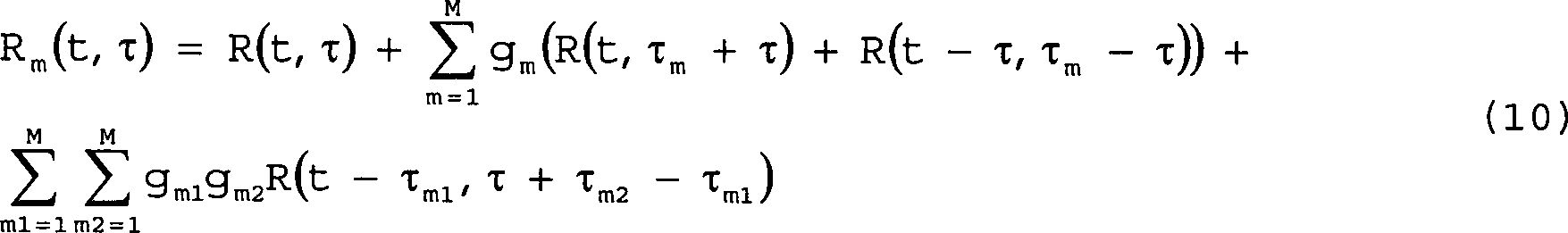
Für ein Zufallssignal s(t) und ein ausreichend großes τ ist R(t, τ) viel kleiner als R(t, 0). Daher sollte der Satz von Verzögerungen {τm} so gewählt werden, dass Rm(t, τ), das nach Gleichung (10) für τ = ± τm berechnet wird, nur einen Term aufweist, für den die Kurzzeit-Autokorrelationsverzögerung gleich null ist. Dieser Term hat eine dominante Wirkung auf die Modulation von Rm(t, τm). Wenn verschiedene τm gewählt werden, werden verschiedene Terme in Gleichung (10) bei der Summierung dominant, wodurch im wesentlichen verschiedene Hostmodifizierungskomponenten "abgestimmt" werden.For a random signal s (t) and a sufficiently large τ, R (t, τ) is much smaller than R (t, 0). Therefore, the set of delays {τ m } should be chosen such that R m (t, τ) computed according to equation (10) for τ = ± τ m has only one term for which the short-term autocorrelation delay equals is zero. This term has a dominant effect on the modulation of R m (t, τ m ). When different τ m are chosen, different terms in equation (10) become dominant in the summation, essentially "tuning" different host modification components.

Der dieser Ausführungsform zugeordnete Decodierer ist in 8 dargestellt. Der Decodierer weist eine Anzahl von Kurzzeit-Autokorrelationsgeneratoren 21a21n auf, wobei jeweils einer für jeden Verzögerungsbetrag vorgesehen ist, für den eine Hostmodifizierungssignalkomponente erzeugt wurde. Die erzeugten Autokorrelationssignale werden durch die Hilfssignalextraktionsschaltung 22 gemeinsam verarbeitet und entweder kombiniert, um das Hilfssignal zu erhalten, oder unabhängig verarbeitet, um eine Anzahl von Hilfsinformationssignalen zu extrahieren.The decoder associated with this embodiment is in 8th shown. The decoder includes a number of short-term autocorrelation generators 21a - 21n each one being for each delay amount for which a host modification signal component has been generated. The generated autocorrelation signals are output by the auxiliary signal extracting circuit 22 processed together and either combined to obtain the auxiliary signal or independently processed to extract a number of auxiliary information signals.

Gemäß einer fünften Implementierung der ersten Ausführungsform der Erfindung können die Hostmodifizierungssignalkomponenten ihre entsprechenden Autokorrelationsverzögerungsbeträge τ im Laufe der Zeit entsprechend einem als "Verzögerungssprung" bezeichneten vordefinierten Verzögerungsmuster ändern. Die Sicherheit des Hilfssignals wird erhöht, indem das Verzögerungssprungmuster geheim gehalten wird. Das Sprungmuster kann als eine Liste aufeinander folgender Autokorrelationsverzögerungen und ihrer Dauer definiert werden. Ein autorisierter Decodierer muss das Sprungmuster sowie die Filter-/Maskierungsparameter und Signalparameter (Symboldauer und andere Symbolmerkmale) kennen. Mehrere Hilfssignale können in dem Hostsignal gleichzeitig übertragen werden, falls ihre Sprungmuster verschieden sind, selbst wenn andere Filter-/Maskierungs- und Signalpa rameter gleich sind.According to one fifth Implementation of the first embodiment of the invention the host modifying signal components their respective autocorrelation delay amounts τ in the course the time corresponding to a predefined as "delay jump" Change delay pattern. The security the auxiliary signal is increased, by the delay jump pattern kept secret. The jump pattern can act as a list on top of each other following autocorrelation delays and their duration. An authorized decoder needs the hopping pattern as well as the filter / masking parameters and signal parameters (Symbol duration and other symbol features) know. Several auxiliary signals can transmitted simultaneously in the host signal if their hopping patterns are different even if other filtering / masking and Signalpa parameters are the same.

Die vorstehend beschriebene erste Ausführungsform der Erfindung kann auf viele Arten modifiziert werden, wie es Fachleuten beim Lesen der vorliegenden Beschreibung verständlich werden wird. Beispielsweise wurde in der vorstehenden Beschreibung der ersten bevorzugten Ausführungsform der Erfindung auf die Wahrnehmung des Hostsignals durch einen "Wahrnehmenden" Bezug genommen. In Zusammenhang mit der Erfindung kann ein Wahrnehmender in dem Fall, in dem das Hostsignal ein Kommunikationssignal ist, eine Vorrichtung, wie bspw. ein Computer, ein Radardetektor oder eine andere elektrische bzw. elektronische Vorrichtung, sein, oder im Fall von Audio- oder Video-Hostsignalen ein Mensch sein. Weiterhin kann die Implementierung der Erfindung unter Verwendung analoger Schaltungsanordnungen sowie auch digitaler Schaltungsanordnungen, wie ASIC (Application Specific Integrated Circuits), digitale Vielzweck-Signalprozessoren, Mikroprozessoren und gleichwertige Vorrichtungen, ausgeführt werden. Weiterhin ist es möglich, dass sich die Eigenschaften des Filters bzw. der Maske im Laufe der Zeit nach einem vordefinierten Muster ändern, das Eigenschaftsänderungen veränderlicher Dauer aufweisen kann. Schließlich sei bemerkt, dass eine ähnliche Funktion wie diejenige gemäß der vorliegenden Erfindung unter manchen Umständen unter Verwendung von Transformations-Bereichsverarbeitungstechniken (wie Fourier- oder Cepstral-Bereich) erhalten werden können, welche unter Verwendung bekannter Algorithmen in der Art der schnellen Fouriertransformation oder FFT implementiert werden können.The above-described first embodiment of the invention can be modified in many ways, as it is for professionals to read of the present description will be understood. For example has been in the above description of the first preferred embodiment of the invention to the perception of the host signal by a "perceiver" reference. In the context of the invention, a percipient in the Case in which the host signal is a communication signal, a device such as a computer, a radar detector or other electrical or electronic device, or in the case of audio or Video host signals to be a human. Furthermore, the implementation the invention using analog circuitry as well Also, digital circuitry, such as ASIC (Application Specific Integrated circuits), general purpose digital signal processors, microprocessors and equivalent devices. It continues possible, that the properties of the filter or the mask in the course change the time according to a predefined pattern, the property changes variable Duration may have. After all be noted that a similar feature like the one according to the present Invention in some circumstances using transform domain processing techniques (such as Fourier or Cepstral region) which can be obtained using known algorithms in the style of fast Fourier transformation or FFT can be implemented.

Zweite AusführungsformSecond embodiment

Mit Bezug auf 9 sei bemerkt, dass gemäß einer zweiten bevorzugten Ausführungsform die Erfindung eine Einbettungsvorrichtung 10a verwendet, um ein Stego-Signal 4a zu erzeugen, das in bezug auf den Gehalt und die Qualität durch ein Abdecksignal 2 übertragener Informationen im wesentlichen gleich ist. Wenn das Abdecksignal 2 beispielsweise ein Video- oder Audiosignal ist, erzeugt das Stego-Signal 4a im wesentlichen das gleiche Video- oder Audioprogramm oder die gleichen Video- oder Audioinformationen, wenn es auf eine Ausgabevorrichtung, wie bspw. eine Videoanzeige oder ein Lautsprecher, angewendet wird.Regarding 9 It should be noted that according to a second preferred embodiment, the invention comprises an embedding device 10a used a stego signal 4a to generate, in terms of content and quality by a cover signal 2 transmitted information is substantially the same. When the cover signal 2 for example, a video or audio signal, generates the stego signal 4a essentially the same video or audio program or the same video or audio information when applied to an output device such as a video display or speaker.

Ein Stego-Schlüssel 9 wird verwendet, um das bestimmte Gebiet des Zeit-, Frequenz- und/oder Raumbereichs des Abdecksignals 2 zu bestimmen und zu spezifizieren, in das die digitalen Daten 6 einzubetten sind, sowie um das verteilte Merkmal des zu modifizierenden Abdecksignals und das Gitter oder die Tabelle, die digitale Datenwerte mit verteilten Merkmalsquantisierungsniveaus korreliert, zu bestimmen und zu spezifizieren. Beispielsweise definieren im Fall eines Audiosignals ein bestimmtes Frequenzband und ein bestimmtes Zeitintervall einen Bereich zum Einbetten eines Datensymbols. Für ein Videosignal wird ein Einbettungsbereich durch ein Frequenzband, ein Zeitintervall in Form eines Bildfelds, eines Rahmens oder einer Reihe von Rahmen und ein bestimmtes Gebiet innerhalb des Felds oder Rahmens spezifiziert. 13 zeigt ein Beispiel der Stego-Schlüsselspezifikationen für ein Frequenzband, ein Zeitintervall, ein verteiltes Signalmerkmal und ein Symbolquanti sierungsgitter für ein Audioabdecksignal. Spezifische Beispiele verteilter Signalmerkmale werden nachstehend bereitgestellt.A stego key 9 is used to determine the particular area of the time, frequency and / or space region of the coverage signal 2 to determine and specify in which the digital data 6 and to determine and specify the distributed feature of the masking signal to be modified and the grid or table that correlates digital data values with distributed feature quantization levels. For example, in the case of an audio signal, a particular frequency band and a particular time interval define an area for embedding a data symbol. For a video signal, an embedding area is specified by a frequency band, a time interval in the form of an image field, a frame or a series of frames, and a specific area within the field or frame. 13 shows an example of the Stego key specifications for a frequency band, a time interval, a distributed signal feature, and a symbol quantization grid for an audio coverage signal. Specific examples of distributed signal characteristics are provided below.

Die Einbettungsvorrichtung moduliert oder modifiziert dann in geeigneter Weise das Abdecksignal 2, um ein Stego-Signal 4a zu erhalten. Das Stego-Signal 4a kann übertragen werden oder in einem Speichermedium, wie bspw. in einem Magnetband, einer CDROM, einem Festkörperspeicher und dergleichen, gespeichert werden, um es später abzurufen und/oder zu übertragen. Die eingebetteten digitalen Daten werden durch eine Extraktionsvorrichtung 20a, die den Stego-Schlüssel 9, der auf das Stego-Signal 4a einwirkt, um die digitalen Daten 6 zu extrahieren, kennt oder Zugang zu diesem hat, wiedergewonnen.The embedding device then modulates or modifies the cover signal as appropriate 2 to a Stego signal 4a to obtain. The stego signal 4a may be transmitted or stored in a storage medium, such as a magnetic tape, a CDROM, a solid state memory, and the like for later retrieval and / or transfer. The embedded digital data is passed through an extraction device 20a holding the stego key 9 that's on the stego signal 4a interacts with the digital data 6 to extract, know or have access to this, regained.

10 zeigt ein Blockdiagramm einer Ausführungsform der Einbettungsvorrichtung 10a. Wie dargestellt ist, werden das Abdecksignal 2 der Stego-Schlüssel 9 und die digitalen Daten 6 in eine Vorrichtung 11a zum Erzeugen eines eingebetteten Signals eingegeben. Die Vorrichtung zum Erzeugen eines eingebetteten Signals moduliert oder modifiziert ein vordefiniertes verteiltes Merkmal des Abdecksignals 2 entsprechend dem Stego-Schlüssel 9 und den digitalen Daten 6 und erzeugt ein eingebettetes Signal 8a. Das Abdecksignal 2 wird dann durch Addieren des eingebetteten Signals 8a zu dem Abdecksignal in einem Addierer 12 modifiziert, um das Stego-Signal 4a zu erzeugen. 10 shows a block diagram of an embodiment of the embedding device 10a , As shown, the cover signal 2 the stego key 9 and the digital data 6 into a device 11a for generating an embedded signal. The embedded signal generating device modulates or modifies a predefined distributed feature of the masking signal 2 according to the stego key 9 and the digital data 6 and generates an embedded signal 8a , The cover signal 2 is then added by adding the embedded signal 8a to the masking signal in an adder 12 modified to the stego signal 4a to create.

11 zeigt die Einzelheiten einer Vorrichtung 11a zum Erzeugen eines eingebetteten Signals, die verwendet wird, um ein einziges eingebettetes Datensignal zu erzeugen. Das Abdecksignal 2 wird im Filter-/Maskierungsblock 30 gefiltert und/oder maskiert, um ein gefiltertes bzw. maskiertes Signal 31 zu erzeugen. Das gefilterte bzw. maskierte Signal 31 besteht aus den ausgewählten Bereichen des Abdecksignals, wie durch den Stego-Schlüssel 9 spezifiziert ist, welche dann zum Einbetten von Datensymbolen verwendet werden. Das Signal 31 wird dann in einen Merkmalsextraktionsblock 32 eingegeben, in dem das zu modifizierende verteilte Merkmal, wie durch den Stego-Schlüssel 9 spezifiziert ist, extrahiert und einem Modulationsparameter-Berechnungsmodul 34 zugeführt wird. Das Modul 34 empfängt in das Abdecksignal einzubettende digitale Daten 6 und bestimmt das Ausmaß der Modulation des Merkmals, das erforderlich ist, um zu bewirken, dass das Merkmal in etwa gleich dem Quantisierungswert wird, der dem einzubettenden digitalen Datensymbol oder -bit entspricht. Das Berechnungsergebnis 7 wird dann einem Modulationsmodul 36 zugeführt, das das gefilterte Signal 31 modifiziert, um die geeignete eingebettete Signalkomponente 8 zu erhalten. Die eingebettete Signalkomponente 8 wird dann im Addierer 12, wie in 10 dargestellt ist, zum Abdecksignal addiert, um das Stego-Signal 4a zu erhalten. 11 shows the details of a device 11a for generating an embedded signal used to generate a single embedded data signal. The cover signal 2 is in the filter / mask block 30 filtered and / or masked to a filtered or masked signal 31 to create. The filtered or masked signal 31 consists of the selected areas of the cover signal, as by the stego key 9 which are then used to embed data symbols. The signal 31 then becomes a feature extraction block 32 in which the distributed feature to be modified, such as the Stego key 9 is specified, extracted and a modulation parameter ter calculation module 34 is supplied. The module 34 receives digital data to be embedded in the cover signal 6 and determines the amount of modulation of the feature required to cause the feature to become approximately equal to the quantization value corresponding to the digital data symbol or bit to be embedded. The calculation result 7 then becomes a modulation module 36 fed, which is the filtered signal 31 modified to the appropriate embedded signal component 8th to obtain. The embedded signal component 8th will then be in the adder 12 , as in 10 is shown added to the cover signal to the Stego signal 4a to obtain.

Es ist weiter möglich, mehrere digitale Datensignale in das Abdecksignal 2 einzubetten, indem mehrere Vorrichtungen zum Erzeugen eingebetteter Signale verwendet werden, die jeweils einen anderen Stego-Schlüssel zum Modifizieren eines anderen Merkmals des Abdecksignals verwenden, und/oder verschiedene Bereiche des Abdecksignals zu verwenden, um mehrere eingebettete Signalkomponenten zu erzeugen, die jeweils zu dem Abdecksignal 2 addiert werden. Alternativ können die verschiedenen Datensignale kaskadenartig eingebet tet werden, wobei die Ausgabe einer Einbettungsvorrichtung zur Eingabe einer anderen Einbettungsvorrichtung wird, wobei ein anderer Stego-Schlüssel verwendet wird.It is also possible to include several digital data signals in the cover signal 2 by using a plurality of embedded signal generating devices, each using a different Stego key to modify another feature of the masking signal, and / or using different regions of the masking signal to produce a plurality of embedded signal components, each to the masking signal 2 be added. Alternatively, the various data signals may be cascaded in, with the output of one embedding device being used to enter another embedding device, using a different Stego key.

Gemäß einer alternativen Ausführungsform kann das Filter/Maskenmodul 30 fortgelassen werden. In diesem Fall wird das Abdecksignal direkt durch die Vorrichtung zum Erzeugen eines eingebetteten Signals modifiziert, um das Stego-Signal zu erzeugen. Dementsprechend wäre der Addierer 12 aus 10 gemäß dieser alternativen Ausführungsform nicht erforderlich.According to an alternative embodiment, the filter / mask module 30 be omitted. In this case, the masking signal is directly modified by the embedded signal generating device to generate the stego signal. Accordingly, the adder would be 12 out 10 Not required according to this alternative embodiment.

Ein Blockdiagramm einer Extraktionsvorrichtung 20a, die zum Wiedergewinnen des in das Stego-Signal eingebetteten digitalen Signals verwendet wird, ist in 12 dargestellt. Das Stego-Signal wird im Filter-/Maskenmodul 30a gefiltert bzw. maskiert, um die Bereiche zu isolieren, in denen die digitalen Daten eingebettet sind. Das gefilterte Signal 31a wird in das Merkmalsextraktionsmodul 32a eingegeben, in dem das Merkmal extrahiert wird. Das extrahierte Merkmal 33a wird dann in das Datenwiedergewinnungsmodul 40 eingegeben, in dem das extrahierte Merkmal der Quantisierungstabelle oder dem Quantisierungsgitter zugeordnet wird, worin quantisierte Merkmalswerte mit spezifischen Datensymbolen korreliert sind. Eine Vielzahl extrahierter Datensymbole wird dann wohlbekannten Fehlererkennungs-, Fehlerkorrektur- und Synchronisationstechniken unterzogen, um die Existenz einer tatsächlichen Nachricht und einer geeigneten Interpretation des Inhalts der Nachricht zu prüfen. Spezifische Beispiele der Modulation verteilter Merkmale des Abdecksignals zur Einbettung von Daten werden nachstehend angegeben.A block diagram of an extraction device 20a used to recover the digital signal embedded in the Stego signal is in 12 shown. The Stego signal is in the filter / mask module 30a filtered or masked to isolate the areas in which the digital data is embedded. The filtered signal 31a becomes the feature extraction module 32a entered in which the feature is extracted. The extracted feature 33a will then be in the data recovery module 40 in which the extracted feature is assigned to the quantization table or the quantization grid, wherein quantized feature values are correlated with specific data symbols. A plurality of extracted data symbols are then subjected to well-known error detection, error correction and synchronization techniques to verify the existence of an actual message and appropriate interpretation of the message content. Specific examples of the modulation of distributed characteristics of the masking signal for embedding data are given below.

Erstes BeispielFirst example

In diesem Beispiel ist das Abdecksignal 2 ein Audiosignal. Bei dieser Ausführungsform wird das Audiosignal zuerst gefiltert, um ein spezifisches Frequenzband zu isolieren, das zum Einbetten einer bestimmten Datennachricht zu verwenden ist, um ein gefiltertes Audiosignal s(t) zu erzeugen. Andere Frequenzbänder können zum Einbetten anderer Nachrichten, entweder gleichzeitig oder in einer kaskadierten Verarbeitungstechnik, verwendet werden. Zusätzlich wird durch das Beschränken des zu modulierenden Frequenzbands auf nur einen Bruchteil des Gesamtsignalspektrums die Wirkung dieser Modulation auf das Host- oder Abdecksignal verringert. Der Filterschritt kann jedoch fortgelassen werden, ohne die Wirksamkeit des Einbettungsprozesses oder die Robustheit der eingebetteten Daten zu beeinträchtigen.In this example, the masking signal is 2 an audio signal. In this embodiment, the audio signal is first filtered to isolate a specific frequency band to be used to embed a particular data message to produce a filtered audio signal s (t). Other frequency bands may be used to embed other messages, either concurrently or in a cascaded processing technique. In addition, limiting the frequency band to be modulated to only a fraction of the total signal spectrum reduces the effect of this modulation on the host or cap signal. However, the filtering step may be omitted without affecting the effectiveness of the embedding process or the robustness of the embedded data.

Als nächstes wird eine Funktion f(s(t)) des gefilterten Audiosignals s(t) folgendermaßen berechnet:

Figure 00300001
wobei abs() eine Absolutwertberechnung bezeichnet und α ein Parameter ist. Systeme, bei denen α = 1 und α = 0,5 verwendet werden, wurden von den vorliegenden Erfindern erfolgreich implementiert.Next, a function f (s (t)) of the filtered audio signal s (t) is calculated as follows:
Figure 00300001
where abs () denotes an absolute value calculation and α is a parameter. Systems using α = 1 and α = 0.5 have been successfully implemented by the present inventors.

Als nächstes wird die Funktion f(s(t)) über aufeinander folgende Zeitintervalle der Länge T integriert, um

Figure 00300002
zu erhalten, wobei das Intervall T der Dauer des Symbols entspricht.Next, the function f (s (t)) is integrated over successive time intervals of length T to
Figure 00300002
, wherein the interval T corresponds to the duration of the symbol.

Im vierten Schritt wird das verteilte Merkmal Fi für das i-te Symbol nach der folgenden Gleichung berechnet:

Figure 00310001
wobei gj, j = 1, 2, ..., N für N vorhergehende Symbole berechnete Verstärkungswerte sind, wie nachstehend dargestellt wird.In the fourth step, the distributed feature F i for the i-th symbol will be according to the following equation expects:
Figure 00310001
where g j , j = 1, 2, ..., N are gain values calculated for N preceding symbols, as shown below.

Im nächsten Schritt wird der Merkmalswert Fi mit einem Satz von Quantisierungsniveaus verglichen, die zu einem bestimmten Symbol gehören, wie durch den Stego-Schlüssel 9 definiert ist. Es wird das Fi nächstgelegene Quantisierungsniveau bestimmt. Beispielsweise gibt es im Fall binärer Ziffern zwei Sätze Q0 und Q1, die den Bits "0" bzw. "1" entsprechen. Der Satz von Quantisierungsniveaus für jeden Satz Q0 und Q1 wird folgendermaßen definiert: Q0 = q(2κ ε), κ = 0, 1, 2, Q1 = q((2κ + 1)ε), κ = 0, 1, 2,(14)wobei ε das Quantisierungsintervall ist, das den Ausgleich zwischen der Robustheit und der Transparenz bestimmt, während q(x) eine monotone Funktion ist. Systeme, bei denen q(x) = x und q(x) = log(x) verwendet werden, wurden erfolgreich implementiert.In the next step, the feature value F i is compared to a set of quantization levels associated with a particular symbol, such as the Stego key 9 is defined. The F i nearest quantization level is determined. For example, in the case of binary digits, there are two sets Q 0 and Q 1 corresponding to bits "0" and "1", respectively. The set of quantization levels for each set Q 0 and Q 1 is defined as follows: Q 0 = q (2κ ε), κ = 0, 1, 2, Q 1 = q ((2κ + 1) ε), κ = 0, 1, 2, (14) where ε is the quantization interval that determines the balance between robustness and transparency, while q (x) is a monotone function. Systems using q (x) = x and q (x) = log (x) have been successfully implemented.

Als nächstes wird der im i-ten Symbolintervall anzuwendende Verstärkungswert gi nach gi = (Qi/Fi)1/α – 1 (15) berechnet, wobei Qi das nächstgelegene Element des zum i-ten Symbol gehörenden Quantisierungssatzes ist.Next, the gain value g i to be applied in the i-th symbol interval becomes after G i = (Q i / F i ) 1 / α - 1 (15 ), where Q i is the nearest element of the quantization set belonging to the i th symbol.

Im folgenden Schritt wird die Verstärkung gi auf alle Signalamplituden im i-ten Symbolintervall angewendet, und das Ergebnis wird wieder zum Audioabdecksignal addiert. Alternativ kann diese Verstärkung vollständig nur im mittleren Abschnitt des Symbolintervalls angewendet werden und zu den Enden des Symbolintervalls verringert werden. Dieser Ansatz verringert die Wahrnehmung der Signalmodifikation auf Kosten einer geringen Reduktion der Symbolrobustheit.In the following step, the gain g i is applied to all signal amplitudes in the ith symbol interval, and the result is added back to the audio masking signal. Alternatively, this gain can be fully applied only in the middle portion of the symbol interval and reduced to the ends of the symbol interval. This approach reduces the perception of signal modification at the expense of a small reduction in symbol robustness.

Zum Extrahieren der eingebetteten Daten filtert die Extraktionsvorrichtung zuerst das Stego-Signal in der gleichen Weise wie die Einbettungsvorrichtung, die durch den Stego-Schlüssel 9 definiert ist. Als nächstes wird das Merkmal nach den Gleichungen (11) bis (13) berechnet, wobei angenommen wird, dass das Zeitintervall T vorab bekannt ist, wie durch den Stego-Schlüssel 9 spezifiziert ist, und der Anfang der eingebetteten Nachricht stimmt mit dem Beginn des Extraktionsprozesses überein.For extracting the embedded data, the extractor first filters the Stego signal in the same way as the embedding device generated by the Stego key 9 is defined. Next, the feature is calculated according to equations (11) to (13), assuming that the time interval T is known in advance, as by the Stego key 9 is specified, and the beginning of the embedded message matches the beginning of the extraction process.

Im nächsten Schritt werden die eingebetteten Datensymbole durch Zuordnen der berechneten Merkmalswerte zu der Quantisierungstabelle oder dem Quantisierungsgitter, wie durch Gleichung (14) definiert ist (durch den Stego-Schlüssel 9 bereitgestellt), Finden der besten Übereinstimmung und Übersetzen des Quantisierungswerts in das entsprechende Symbol extrahiert.In the next step, the embedded data symbols are assigned by assigning the calculated feature values to the quantization table or quantization grid as defined by Equation (14) (by the Stego key 9 provided), finding the best match, and translating the quantization value into the corresponding symbol.

Im folgenden Schritt werden aufeinanderfolgende extrahierte Symbole miteinander verknüpft und mit einem Satz möglicher Nachrichten verglichen. Falls eine Übereinstimmung gefunden wird, wird die Nachricht an einen Benutzer oder eine höhere Datenprotokollschicht ausgegeben. Falls keine Übereinstimmung gefunden wird, werden wiederholte Versuche zu einer Extraktion ausgeführt, indem die Anfangszeit der Nachricht leicht um dT verschoben wird, wobei es sich um einen kleinen Bruchteil des Intervalls T handelt (beispielsweise 0,01T bis 0,1T).in the following step will be successive extracted symbols linked together and with a set of possible ones News compared. If a match is found, The message is sent to a user or higher data protocol layer output. If no match is found, repeated attempts are made to extraction by the start time of the message is slightly shifted by dT, where it is a small fraction of the interval T (for example 0.01T to 0.1T).

Zweites BeispielSecond example

In diesem Beispiel wird nach einem Filter-/Maskierungsschritt, ähnlich dem ersten Beispiel, eine Funktion f(s(t)) des gefilterten Audiosignals s (t) nach der folgenden Gleichung berechnet: f(s(t)) = s2m(t) (16)wobei m eine ganze Zahl ist. Systeme, bei denen m = 1 und m = 2 verwendet werden, wurden erfolgreich implementiert.In this example, after a filtering / masking step, similar to the first example, a function f (s (t)) of the filtered audio signal s (t) is calculated according to the following equation: f (s (t)) = s 2m (t) (16) where m is an integer. Systems using m = 1 and m = 2 have been successfully implemented.

Als nächstes werden zwei Integrale jeweils über die erste Hälfte und die zweite Hälfte des i-ten Symbolintervalls erzeugt:

Figure 00330001
Next, two integrals are generated over the first half and the second half of the ith symbol interval, respectively:
Figure 00330001

Im folgenden Schritt wird das verteilte Merkmal Fi für das i-te Symbol nach der folgenden Gleichung berechnet:

Figure 00340001
In the following step, the distributed feature F i for the ith symbol is calculated according to the following equation:
Figure 00340001

Als nächstes wird das berechnete Merkmal Fi mit einem vordefinierten Satz von Quantisierungswerten für das gegebene einzubettende Symbol verglichen, und es wird der nächstgelegene Quantisierungswert gewählt. Bei dieser Ausführungsform sind die Sätze Q0 und Q1 von Quantisierungswerten für binäre Ziffernsymbole "0" und "1" als Q0 = q((2κ + 0,5)ε), κ = 0, ± 1, ± 2, Q1 = q((2κ – 0,5)ε), κ = 0, ± 1, ± 2,(19)definiert, wobei ε das Quantisierungsintervall ist, das den Ausgleich zwischen der Robustheit und der Transparenz bestimmt, während q(x) eine monotone Funktion ist. Erfolgreiche Implementationen wurden für q(x) = x und q(x) = x + ε/2 ausgeführt.Next, the calculated feature F i is compared with a predefined set of quantization values for the given symbol to be embedded, and the nearest quantization value is chosen. In this embodiment, the sets Q 0 and Q 1 of quantization values for binary digit symbols are "0" and "1" as Q 0 = q ((2κ + 0.5) ε), κ = 0, ± 1, ± 2, Q 1 = q ((2κ - 0.5) ε), κ = 0, ± 1, ± 2, (19) where ε is the quantization interval that determines the balance between robustness and transparency, while q (x) is a monotone function. Successful implementations have been performed for q (x) = x and q (x) = x + ε / 2.

Im nächsten Schritt wird die im i-ten Symbolintervall anzuwendende Verstärkung gi nach

Figure 00340002
berechnet, wobei Qi das nächstgelegene Element des zum i-ten Symbol gehörenden Quantisierungssatzes ist. Gleichung (20) wird als eine Näherung abgeleitet, die gut für kleine Werte von gi gilt und den Rechenaufwand in bezug auf eine exakte Formel bei vernachlässigbaren Wirkungen auf die Ro bustheit des Systems verringert.In the next step, the gain g i to be applied in the ith symbol interval is followed by
Figure 00340002
where Q i is the nearest element of the quantization set belonging to the i th symbol. Equation (20) is derived as an approximation that is good for small values of g i and reduces the computational effort with respect to an exact formula with negligible effects on the system's roughness.

Als nächstes wird die berechnete Verstärkung gi auf alle Signalamplituden im i-ten Symbolintervall angewendet, und das Ergebnis wird wieder zum Abdecksignal addiert. Alternativ wird die Verstärkung vollständig nur im mittleren Abschnitt des Intervalls angewendet und nimmt zu den Enden des Intervalls hin ab.Next, the calculated gain g i is applied to all signal amplitudes in the ith symbol interval, and the result is added back to the cover signal. Alternatively, the gain is completely applied only in the middle portion of the interval and decreases toward the ends of the interval.

Der Extraktionsprozess folgt einer zu der vorstehend für das erste Beispiel beschriebenen analogen Sequenz.Of the Extraction process follows one of the above for the first one Example analog sequence described.

Nachdem die Erfindung nun beschrieben wurde, werden Fachleute verstehen, dass diese auf vielerlei Arten abgeändert werden kann, ohne vom Schutzumfang der Erfindung abzuweichen, der durch die folgenden Ansprüche definiert ist. Alle solche Modifikationen, die Fachleuten einfallen werden, sollen durch die folgenden Ansprüche abgedeckt werden.After this the invention has now been described, will be understood by those skilled in the art, that this can be changed in many ways, without the To deviate scope of the invention, which is defined by the following claims is. All such modifications that professionals will come up with, are intended by the following claims be covered.

Claims (50)

Verfahren zum Einbetten eines Informationssymbols in ein analoges Abdecksignal (2), mit den folgenden Schritten: Auswählen eines verteilten Signalmerkmals des Abdecksignals, Berechnen eines Werts des ausgewählten verteilten Signalmerkmals des Abdecksignals über einen vordefinierten Bereich, und gekennzeichnet durch die folgenden Schritte: Vergleichen des berechneten verteilten Signalmerkmalwertes mit einem vordefinierten Satz von Quantisierungswerten entsprechend gegebenen Informationssymbolen und Bestimmen eines Zielquantisierungswerts entsprechend dem Informationssymbol, das einzubetten ist, Berechnen des Betrags an Änderung, der in dem Abdecksignal erforderlich ist, um das berechnete verteilte Signalmerkmal zu dem Zielquantifizierungswert zu modifizieren, und Modifizieren des Abdecksignals entsprechend dem berechneten Betrag an Änderung durch Erzeugen einer modifizierten Version (8, 8a) des Abdecksignals in Übereinstimmung mit dem berechneten Betrag an Änderung und Einbetten der modifizierten Version des Abdecksignals in das ursprüngliche Abdecksignal, um ein modifiziertes Abdecksignal (4, 4a) bereitzustellen, in dem das Informationssymbol eingebettet ist.Method for embedding an information symbol in an analog cover signal ( 2 comprising: selecting a distributed signal characteristic of the coverage signal, calculating a value of the selected distributed signal feature of the coverage signal over a predefined range, and characterized by the steps of: comparing the calculated distributed signal feature value to a predefined set of quantization values according to given information symbols and Determining a target quantization value corresponding to the information symbol to be embedded, calculating the amount of change required in the masking signal to modify the calculated distributed signal characteristic to the target quantization value, and Modifying the masking signal according to the calculated amount of change by creating a modified version ( 8th . 8a ) of the masking signal in accordance with the calculated amount of change and embedding of the modified version of the masking signal into the original masking signal to produce a modified masking signal ( 4 . 4a ) in which the information symbol is embedded. Verfahren nach Anspruch 1, bei dem der Schritt des Berechnens eines verteilten Signalmerkmals die Schritte des Bestimmens eines Bereichs des Abdecksignals, in dem das Informationssignal einzubetten ist, des Abgrenzens bzw. Isolierens des Bereichs des Abdecksignals und des Berechnens des Signalmerkmalwerts von dem isolierten Bereich umfasst.The method of claim 1, wherein the step of Calculating a distributed signal feature, the steps of determining a portion of the cover signal in which the information signal is to be embedded, the delimiting or insulating the area of Masking signal and calculating the signal feature value from the includes isolated area. Verfahren nach Anspruch 1, bei dem der vordefinierte Satz an Quantisierungswerten ein Mehrfaches an Quantisierungswerten für jedes definierte Informationssymbol enthält.The method of claim 1, wherein the predefined Set of quantization values a multiple of quantization values for each contains a defined information symbol. Verfahren nach Anspruch 1, bei dem der Schritt des Modifizierens des Abdecksignals den Schritt des Produzierens einer eingebetteten Signalkomponente (8a) entsprechend dem kalkulierten Betrag an Änderung zum Hinzufügen zu dem Abdecksignal umfasst.The method of claim 1, wherein the step of modifying the masking signal comprises the step of producing an embedded signal component ( 8a ) according to the calculated amount of change for addition to the cover signal. Verfahren nach Anspruch 1, bei dem der vordefinierte Bereich ein ausgewähltes Intervall in dem Zeitbereich des Abdecksignals enthält.The method of claim 1, wherein the predefined Area a selected one Contains interval in the time range of the cover signal. Verfahren nach Anspruch 1, bei dem der vordefinierte Bereich ein ausgewähltes Frequenzband des Abdecksignals enthält.The method of claim 1, wherein the predefined Area a selected one Contains frequency band of the cover signal. Verfahren nach Anspruch 1, bei dem der Schritt des Modifizierens den Schritt des Änderns von zumindest einigen der Amplituden der Abdecksignalkomponenten innerhalb des vordefinierten Intervalls in Übereinstimmung mit dem berechneten Betrag an Änderung umfasst.The method of claim 1, wherein the step of Modifying the step of changing at least some of the amplitudes of the cover signal components within the predefined interval in accordance with the calculated Amount of change includes. Verfahren nach Anspruch 1, bei dem der Schritt des Modifizierens den Schritt des Änderns der Amplituden aller Abdecksignalkomponenten innerhalb des vordefinierten Intervalls in Übereinstimmung mit dem berechneten Betrag an Änderung umfasst.The method of claim 1, wherein the step of Modifying the step of changing the amplitudes of all coverage signal components within the predefined one Intervals in accordance with the calculated amount of change includes. Verfahren zum Extrahieren eines Informationssymbols, das in ein analoges Abdecksignal eingebettet ist, mit folgenden Schritten: Berechnen eines verteilten Signalmerkmalwerts des Abdecksignals über einen vordefinierten Bereich, und gekennzeichnet durch folgende Schritte: Vergleichen des berechneten Signalmerkmalwerts mit einem vordefinierten Satz an Quantisierungswerten entsprechend den gegebenen Informationssymbolen und Bestimmen, welcher Quantisierungswert dem berechneten Signalmerkmalswert entspricht, und Übersetzen bzw. Übertragen des vorbestimmten Quantisierungswerts in das Informationssymbol, das in dem Abdecksignal enthalten ist, und Ausgeben des Informationssymbols.Method for extracting an information symbol, which is embedded in an analog cover signal, with the following steps: Calculating a distributed signal feature value of Cover signal over a predefined area, and characterized by the following Steps: Compare the calculated signal feature value with a predefined set of quantization values corresponding to given information symbols and determining which quantization value corresponds to the calculated signal feature value, and Translate or transfer the predetermined quantization value in the information symbol, contained in the cover signal and outputting the information symbol. Verfahren nach Anspruch 9, bei dem der Schritt des Berechnens eines verteilten Signalmerkmals die Schritte des Bestimmens eines Bereichs des Abdecksignals, in dem das Informationssignal zu kodieren ist, des Isolierens des Bereichs des Abdecksignals und des Berechnens des Signalmerkmalwerts von dem isolierten Bereich umfasst.The method of claim 9, wherein the step of Calculating a distributed signal feature, the steps of determining a portion of the cover signal in which the information signal to be coded, isolating the area of the masking signal and calculating the signal feature value from the isolated area includes. Verfahren nach Anspruch 9, bei dem der vordefinierte Satz an Quantisierungswerten ein Mehrfaches an Quantisierungswerten für jedes definierte Informationssymbol enthält.The method of claim 9, wherein the predefined Set of quantization values a multiple of quantization values for each contains a defined information symbol. Verfahren nach Anspruch 9, bei dem der vordefinierte Bereich ein ausgewähltes Intervall in dem Zeitbereich des Abdecksignals enthält.The method of claim 9, wherein the predefined Area a selected one Contains interval in the time range of the cover signal. Verfahren nach Anspruch 9, bei dem der vordefinierte Bereich ein ausgewähltes Frequenzband des Abdecksignals enthält.The method of claim 9, wherein the predefined Area a selected one Contains frequency band of the cover signal. Vorrichtung zum Einbetten und Extrahieren von Informationssymbolen in ein analoges Abdecksignal (2), mit: Mitteln (32) zum Berechnen eines verteilten Signalmerkmalwerts eines ausgewählten verteilten Signalmerkmals des Abdecksignals über einen vordefinierten Bereich, und gekennzeichnet durch: Mittel (34) zum Vergleichen des berechneten verteilten Signalmerkmalwerts mit einem vordefinierten Satz an Quantisierungswerten entsprechend gegebenen Informationssymbolen und Bestimmen eines Zielquantisierungswerts entsprechend dem Informationssymbol, das einzubetten ist, Mittel (34) zum Berechnen des Betrags an Änderung, der in dem Abdecksignal erforderlich ist, um das berechnete verteilte Signalmerkmal zu dem Zielquantisierungswert zu modifizieren, Mittel (36, 12) zum Modifizieren des Abdecksignals entsprechend dem berechneten Betrag an Änderung durch Erzeugen einer modifizierten Version (8, 8a) des Abdecksignals in Übereinstimmung mit dem berechneten Betrag an Änderung und Einbetten der modifizierten Version des Abdecksignals in das ursprüngliche Abdecksignal, um ein modifiziertes Abdecksignal (4, 4a) bereitzustellen, in dem das Informationssymbol eingebettet ist, Mittel (32a) zum Berechnen eines verteilten Signalmerkmalwerts des modifizierten Abdecksignals über einen vordefinierten Bereich, Mittel (32a) zum Vergleichen des berechneten Signalmerkmalwerts des modifizierten Abdecksignals mit einem vordefinierten Satz an Quantisierungswerten entsprechend gegebenen Informationssymbolen und Bestimmen, welcher Quantisierungswert dem berechneten Signalmerkmalwert entspricht, und Mittel (40) zum Übertragen bzw. Übersetzen des vorbestimmten Quantisierungswerts in das Informationssymbol, das in dem modifizierten Abdecksignal enthalten ist, und Ausgeben des Informationssymbols.Device for embedding and extracting information symbols into an analogue coverage signal ( 2 ), with: means ( 32 ) for calculating a distributed signal feature value of a selected distributed signal feature of the coverage signal over a predefined range, and characterized by: means ( 34 ) for comparing the calculated distributed signal feature value with a predefined set Quantization values corresponding to given information symbols and determining a target quantization value corresponding to the information symbol to be embedded, means ( 34 ) for calculating the amount of change required in the masking signal to modify the calculated distributed signal characteristic to the target quantization value, means ( 36 . 12 ) for modifying the masking signal according to the calculated amount of change by generating a modified version ( 8th . 8a ) of the masking signal in accordance with the calculated amount of change and embedding of the modified version of the masking signal into the original masking signal to produce a modified masking signal ( 4 . 4a ) in which the information symbol is embedded, means ( 32a ) for calculating a distributed signal feature value of the modified masking signal over a predefined range, means ( 32a ) for comparing the calculated signal feature value of the modified masking signal with a predefined set of quantization values according to given information symbols and determining which quantization value corresponds to the calculated signal feature value, and means ( 40 ) for transmitting the predetermined quantization value into the information symbol included in the modified masking signal and outputting the information symbol. Vorrichtung nach Anspruch 14, bei der das Mittel (32) zum Berechnen eines verteilten Signalmerkmals Mittel zum Bestimmen eines Bereichs des Abdecksignals, in dem das Informationssignal zu kodieren ist, Mittel zum Isolieren des Bereichs des Abdecksignals und Mittel zum Berechnen des Signalmerkmals von dem isolierten Bereich umfasst.Device according to Claim 14, in which the means ( 32 ) for calculating a distributed signal feature, means for determining a region of the cover signal in which the information signal is to be coded, means for isolating the region of the cover signal and means for calculating the signal feature from the isolated region. Vorrichtung nach Anspruch 14, bei der der vordefinierte Satz an Quantisierungswerten ein Mehrfaches an Quantisierungswerten für jedes definierte Informationssymbol enthält.Apparatus according to claim 14, wherein the predefined Set of quantization values a multiple of quantization values for each contains a defined information symbol. Vorrichtung nach Anspruch 14, die weiterhin Mittel (36) zum Produzieren einer eingebetteten Signalkomponente zum Hinzufügen zu dem Abdecksignal aufweist, entsprechend dem berechneten Betrag an Änderung.Apparatus according to claim 14, further comprising means ( 36 ) for producing an embedded signal component for adding to the cover signal, according to the calculated amount of change. Vorrichtung nach Anspruch 14, bei der der vordefinierte Bereich ein ausgewähltes Intervall in dem Zeitbereich des Abdecksignals enthält.Apparatus according to claim 14, wherein the predefined Area a selected one Contains interval in the time range of the cover signal. Vorrichtung nach Anspruch 14, bei der der vordefinierte Bereich ein ausgewähltes Frequenzband des Abdecksignals enthält.Apparatus according to claim 14, wherein the predefined Area a selected one Contains frequency band of the cover signal. Vorrichtung nach Anspruch 14, bei der das Mittel (36) zum Modifizieren ein Mittel zum Ändern zumindest einiger der Amplituden von Abdecksignalkomponenten innerhalb des vordefinierten Bereichs in Übereinstimmung mit dem berechneten Betrag an Änderung umfasst.Device according to Claim 14, in which the means ( 36 ) for modifying comprises means for changing at least some of the amplitudes of coverage signal components within the predefined area in accordance with the calculated amount of change. Vorrichtung zum Einbetten eines Informationssymbols in ein analoges Abdecksignal (2) mit: Mitteln (32) zum Berechnen eines verteilten Signalmerkmalwerts eines ausgewählten verteilten Signalmerkmals des Abdecksignals über einen vordefinierten Bereich, und gekennzeichnet durch: Mittel (36, 12) zum Modifizieren des Abdecksignals durch Ändern zumindest einiger der Amplituden von Abdecksignalkomponenten innerhalb des vordefinierten Bereichs als eine Funktion des berechneten verteilten Signalmerkmalwerts, um ein modifiziertes Abdecksignal mit einem verteilten Signalmerkmalswert zu erhalten, in dem vordefinierten Bereich entsprechend dem Informationssymbol.Device for embedding an information symbol in an analogue cover signal ( 2 ) with: means ( 32 ) for calculating a distributed signal feature value of a selected distributed signal feature of the coverage signal over a predefined range, and characterized by: means ( 36 . 12 ) for modifying the masking signal by changing at least some of the amplitudes of masking signal components within the predefined area as a function of the calculated distributed signal feature value to obtain a modified masking signal having a distributed signal feature value in the predefined area corresponding to the information symbol. Vorrichtung nach Anspruch 21, die weiterhin aufweist: Mittel (34) zum Vergleichen des berechneten Signalmerkmalwerts mit einem vordefinierten Satz an Quantisierungswerten entsprechend gegebenen Informationssymbolen und Bestimmen eines Zielquantisierungswerts entsprechend dem Informationssymbol, das einzubetten ist, und Mittel (34) zum Berechnen des Betrags an Änderung, der in dem Abdecksignal erforderlich ist, um das berechnete Signalmerkmals zu dem Zielquantisierungswert zu modifizieren, wobei das Mittel (36, 12) zum Modifizieren des Abdecksignals das Abdecksignal entsprechend dem berechneten Wert an Änderung modifiziert.The apparatus of claim 21, further comprising: means ( 34 ) for comparing the calculated signal feature value with a predefined set of quantization values according to given information symbols and determining a target quantization value corresponding to the information symbol to be embedded, and means ( 34 ) for calculating the amount of change required in the masking signal to modify the calculated signal characteristic to the target quantization value, wherein the means ( 36 . 12 ) modifies the masking signal to modify the masking signal according to the calculated value of change. Vorrichtung zum Extrahieren eines Informationssymbols, das in ein analoges Abdecksignal eingebettet ist, mit: Mitteln (32a) zum Berechnen eines verteilten Signalmerkmalwerts des Abdecksignals über einen vordefinierten Bereich, und gekennzeichnet durch: Mittel (32a) zum Vergleichen des berechneten Signalmerkmalwerts mit einem vordefinierten Satz an Quantisierungswerten entsprechend gegebenen Informationssymbolen und Bestimmen, welcher Quantisierungswert dem berechneten Signalmerkmalswert entspricht, und Mittel (40) zum Übertragen des bestimmten Quantisierungswerts in das Informationssymbol, das in dem Abdecksignal enthalten ist, und Ausgeben des Informationssymbols.Apparatus for extracting an information symbol embedded in an analogue coverage signal, comprising: means ( 32a ) for calculating a distributed signal characteristic value of the coverage signal over a predefined range, and characterized by: means ( 32a ) for comparing the calculated signal feature value with a predefined set of quanti according to given information symbols and determining which quantization value corresponds to the calculated signal feature value, and means ( 40 ) for transmitting the determined quantization value into the information symbol included in the cover signal and outputting the information symbol. Verfahren zum Einbetten von Informationssymbolen auf einem analogen Abdecksignal entsprechend Anspruch 1, bei dem der Schritt des Berechnens eines verteilten Signalmerkmalwerts den Schritt des Bestimmens eines kurzzeitigen bzw. kurzfristigen Autokorrelationsfunktionswerts des Abdecksignals umfasst, der Schritt des Vergleichens den Schritt des Berechnens eines Werts der kurzfristigen Autokorrelationsfunktion (bzw. Kurzzeit-Autokorrelationsfunktion) des Abdecksignals entsprechend dem Zielquantisierungswert des Informationssignals in Übereinstimmung mit einer vordefinierten Beziehung zwischen Informationssignalwert und Abdecksignalautokorrelationswert umfasst, der Schritt des Berechnens den Schritt des Entwickelns eines Abdeckmodifizierungssignals umfasst, um das Abdecksignal derart zu modifizieren, dass der Wert der Kurzzeit-Autokorrelationsfunktion des modifizierten Abdecksignals dem berechneten Wert entsprechen wird, und, der Schritte des Modifizierens den Schritt des Modifizierens des Abdecksignals mit dem Abdeckmodifizierungssignal umfasst.Method for embedding information symbols on an analog cover signal according to claim 1, wherein the step of calculating a distributed signal feature value Step of determining a short-term autocorrelation function value the cover signal comprises, the step of comparing that Step of calculating a value of the short-term autocorrelation function (resp. Short term autocorrelation function) of the masking signal, respectively the target quantization value of the information signal in accordance with a predefined relationship between information signal value and Includes cover signal autocorrelation value, the step of calculating comprising the step of developing a cap modification signal, to modify the masking signal such that the value of the short term autocorrelation function of the modified masking signal correspond to the calculated value will, and, the steps of modifying the step of modifying of the cover signal with the cover modification signal. Verfahren zum Einbetten von Informationssymbolen auf einem analogen Abdecksignal nach Anspruch 24, bei dem das Abdeckmodifizierungssignal (8) von dem Abdecksignal (2) entwickelt wird.Method for embedding information symbols on an analog cover signal according to Claim 24, in which the cover modification signal ( 8th ) of the cover signal ( 2 ) is developed. Verfahren zum Einbetten von Informationssymbolen auf einem analogen Abdecksignal nach Anspruch 24, bei dem der Schritt des Modifizierens des Abdecksignals den Schritt des Hinzufügens des Abdeckmodifizierungssignals zu dem Abdecksignal umfasst.Method for embedding information symbols on an analog cover signal according to claim 24, wherein the step modifying the masking signal, the step of adding the Cover modification signal to the cover signal comprises. Verfahren zum Einbetten von Informationssymbolen auf einem analogen Abdecksignal nach Anspruch 25, bei dem der Schritt des Entwickelns den Schritt des Variierens der Verstärkung des Abdecksignals als eine Funktion der vordefi nierten Beziehung und der Werte des Abdecksignals und des Hilfsinformationssignals (6) umfasst.A method of embedding information symbols on an analogue masking signal according to claim 25, wherein the step of developing comprises the step of varying the gain of the masking signal as a function of the predefined relationship and the values of the masking signal and the auxiliary information signal ( 6 ). Verfahren zum Einbetten von Informationssymbolen auf einem analogen Abdecksignal nach Anspruch 25, das weiterhin den Schritt des Modifizierens eines Parameters des Abdecksignals umfasst, um ein gefiltertes Abdecksignal zur Verwendung beim Entwickeln des Abdeckmodifizierungssignals zu erzeugen.Method for embedding information symbols on an analog cover signal according to claim 25, further the step of modifying a parameter of the masking signal includes a filtered masking signal for use in development of the cover modification signal. Verfahren zum Einbetten von Informationssymbolen auf einem analogen Abdecksignal nach Anspruch 28, bei dem der Parameter den Frequenzgehalt des Abdecksignals umfasst.Method for embedding information symbols on an analog cover signal according to claim 28, wherein the parameter includes the frequency content of the cover signal. Verfahren zum Einbetten von Informationssymbolen auf einem analogen Abdecksignal nach Anspruch 28, bei dem der Parameter den Raumgehalt des Abdecksignals umfasst.Method for embedding information symbols on an analog cover signal according to claim 28, wherein the parameter includes the volume content of the cover signal. Verfahren zum Einbetten von Informationssymbolen auf einem analogen Abdecksignal nach Anspruch 28, bei dem der Parameter einen Zeitbereich des Abdecksignals umfasst.Method for embedding information symbols on an analog cover signal according to claim 28, wherein the parameter a time range of the cover signal. Verfahren zum Einbetten von Informationssymbolen auf einem analogen Abdecksignal nach Anspruch 28, bei dem der Parameter eine Abtastrate des Abdecksignals umfasst.Method for embedding information symbols on an analog cover signal according to claim 28, wherein the parameter a sampling rate of the cover signal. Verfahren zum Einbetten von Informationssymbolen auf einem analogen Abdecksignal nach Anspruch 24, bei dem das analoge Abdecksignal ein Audiosignal ist.Method for embedding information symbols on an analog cover signal according to claim 24, wherein the analogue Cover signal is an audio signal. Verfahren zum Einbetten von Informationssymbolen auf einem analogen Abdecksignal nach Anspruch 24, bei dem das analoge Abdecksignal ein Videosignal ist.Method for embedding information symbols on an analog cover signal according to claim 24, wherein the analogue Cover signal is a video signal. Verfahren zum Einbetten von Informationssymbolen auf einem analogen Abdecksignal nach Anspruch 24, bei dem die vordefinierte Beziehung zwischen dem Wert der Kurzzeit-Autokorrelationsfunktion und den Hilfsinformationssymbolwerten als eine Funktion von vorbestimmten Werten von Hilfsinformationssymbolen variiert.Method for embedding information symbols on an analog cover signal according to claim 24, wherein the predefined Relationship between the value of the short-term autocorrelation function and the auxiliary information symbol values varies as a function of predetermined values of auxiliary information symbols. Verfahren zum Einbetten von Informationssymbolen auf einem analogen Abdecksignal nach Anspruch 27, bei dem der Schritt des Variierens der Verstärkung den Schritt des Variierens der Verstärkung des Abdecksignals um eine vorbestimmte Größe mit einer ersten Polarität in einer ersten Hälfte eines Informationssymbolintervalls und des Variierens der Verstärkung des Abdecksignals in einer zweiten Hälfte des Informationssymbolintervalls um die vorbestimmte Größe mit einer zweiten Polarität entgegengesetzt der ersten Polarität umfasst.A method of embedding information symbols on an analog cover signal as claimed in claim 27, wherein the step of varying the gain comprises the step of varying the gain of the cover signal by a predetermined magnitude with a first polarity in a first half of an information symbol bolintervalls and varying the gain of the cover signal in a second half of the information symbol interval by the predetermined magnitude with a second polarity opposite to the first polarity. Verfahren zum Einbetten von Informationssymbolen auf einem analogen Abdecksignal nach Anspruch 24, bei dem das Abdeckmodifizierungssignal aus einer Summe einer Mehrzahl von modifizierenden Signalkomponenten besteht, die jeweils einen verschiedenen Betrag einer Verzögerung bezüglich des Abdecksignals haben.Method for embedding information symbols on an analog cover signal according to claim 24, wherein the cover modification signal from a sum of a plurality of modifying signal components each having a different amount of delay with respect to the Cover signal have. Verfahren zum Einbetten von Informationssymbolen auf einem analogen Abdecksignal nach Anspruch 25, bei dem das Abdeckmodifizierungssignal um eine vorbestimmte Verzögerung τ bezüglich des Abdecksignals verzögert ist.Method for embedding information symbols on an analog cover signal according to claim 25, wherein the cover modification signal by a predetermined delay τ with respect to Cover signal delayed is. Verfahren zum Einbetten von Informationssymbolen auf einem analogen Abdecksignal nach Anspruch 38, bei dem die vorbestimmte Verzögerung τ als eine Funktion einer Zeit entsprechend einem vorbestimmten Verzögerungsmuster variiert.Method for embedding information symbols on an analog cover signal according to claim 38, wherein the predetermined Delay τ as one Function of a time corresponding to a predetermined delay pattern varied. Verfahren zum Extrahieren von Informationssymbolen, die auf einem analogen Abdecksignal nach Anspruch 9 eingebettet sind, wobei der Schritt des Berechnens den Schritt des Berechnens einer kurzfristigen Autokorrelationsfunktion des kodierten Abdecksignals umfasst, der Schritt des Vergleichens den Schritt des Bestimmens des Werts der erzeugten Autokorrelationsfunktion umfasst, und der Schritt des Übertragens den Schritt des Bestimmens eines Werts eines Informationssymbols als eine Funktion des Werts der erzeugten Autokorrelationsfunktion und einer vordefinierten Beziehung zwischen Informationssymbolwerten und Autokorrelationsfunktionswerten umfasst.Method for extracting information symbols, embedded on an analog cover signal according to claim 9 , wherein the step of calculating comprises the step of calculating a short-term autocorrelation function of the coded masking signal includes, the step of comparing comprises the step of determining the value of the generated autocorrelation function, and of the Step of transferring the step of determining a value of an information symbol as a function of the value of the generated autocorrelation function and a predefined relationship between information symbol values and autocorrelation function values. Verfahren zum Extrahieren von Informationssymbolen, die auf einem analogen Abdecksignal codiert sind, nach Anspruch 40, wobei der Schritt des Berechnens einer Kurzzeit-Autokorrelationsfunktion des kodierten Abdecksignals eine Verzögerung τ verwendet, und wobei der Schritt des Bestimmens eines Werts eines Informationssymbols die Schritte umfasst: Berechnen einer Kurzzeit-Autokorrelationsfunktion mit Null-Verzögerung, und Berechnen eines normalisierten Autokorrelationssignals durch Teilen der Autokorrelationsfunktion mit der Verzögerung τ durch die Autokorrelationsfunktion mit Null-Verzögerung.Method for extracting information symbols, which are coded on an analog cover signal, according to claim 40, wherein the step of calculating a short-term autocorrelation function the coded masking signal uses a delay τ, and wherein the step of determining a value of an information symbol, the steps includes: Calculate a short-term autocorrelation function with zero delay, and Calculating a normalized autocorrelation signal by dividing the autocorrelation function by the delay τ by the Autocorrelation function with zero delay. Verfahren zum Extrahieren von Informationssymbolen, die auf einem analogen Abdecksignal codiert sind, nach Anspruch 41, wobei das Abdeckmodifizierungssignal aus einer Summe einer Mehrzahl von modifizierenden Signalkomponenten besteht, die jeweils einen verschiedenen Betrag einer Verzögerung bezüglich des Abdecksignals haben, und der Schritt des Bestimmens eines Werts eines Informationssymbols den Schritt des Durchführens der Schritte des Bestimmens von Werten für jede der Mehrzahl von modifizierenden Signalkomponenten umfasst.Method for extracting information symbols, which are coded on an analog cover signal, according to claim 41, wherein the cover modification signal is a sum of a plurality consists of modifying signal components, each one different amount of a delay concerning the Cover signal, and the step of determining a value an information symbol, the step of performing the steps of determining of values for includes each of the plurality of modifying signal components. Verfahren zum Extrahieren von Informationssymbolen, die auf einem analogen Abdecksignal eingebettet sind, nach Anspruch 41, bei dem die vorbestimmte Verzögerung τ als eine Funktion einer Zeit in Übereinstimmung mit einem vorbestimmten Verzögerungsmuster variiert.Method for extracting information symbols, which are embedded on an analog cover signal, according to claim 41, in which the predetermined delay τ as a function of time in accordance with a predetermined delay pattern varied. Vorrichtung zum Einbetten von Informationssymbolen auf einem analogen Abdecksignal (2) nach Anspruch 21, bei der das Mittel zum Berechnen Mittel zum Bestimmen eines Werts der Kurzzeit-Autokorrelationsfunktion des Abdecksignals umfasst, wobei die Vorrichtung weiterhin aufweist: Mittel (11) zum Bestimmen eines Werts eines Hilfsinformationssignals, das ein Informationssymbol enthält, Mittel (11) zum Berechnen eines Werts der kurzfristigen Autokorrelationsfunktion des Abdecksignals entsprechend dem bestimmten Wert des Hilfsinformationssignals in Übereinstimmung mit einer vordefinierten Beziehung zwischen Hilfsinformationssignalwert und Abdecksignalkorrelationswert, Mittel (11) zum Entwickeln eines Abdeckmodifizierungssignals (8) zum Modifizieren des Abdecksignals, so dass der Wert der Kurzzeit-Autokorrelationsfunktions des modifizierten Abdecksignals dem berechneten Wert entsprechen wird, und wobei das Mittel zum Modifizieren das Abdecksignal mit dem Abdeckmodifizierungssignal modifiziert.Device for embedding information symbols on an analogue cover signal ( 2 ) according to claim 21, wherein the means for calculating comprises means for determining a value of the short-term autocorrelation function of the cover signal, the device further comprising: means ( 11 ) for determining a value of an auxiliary information signal containing an information symbol, means ( 11 ) for calculating a value of the short-term autocorrelation function of the masking signal corresponding to the determined value of the auxiliary information signal in accordance with a predefined relationship between the auxiliary information signal value and the masking signal correlation value; 11 ) for developing a cover modification signal ( 8th ) for modifying the masking signal such that the value of the short term autocorrelation function of the modified masking signal will correspond to the calculated value, and wherein the means for modifying modifies the masking signal with the masking modification signal. Vorrichtung zum Extrahieren von Informationssymbolen, die auf einem analogen Abdecksignal eingebettet sind, nach Anspruch 23, bei der das Mittel zum Berechnen Mittel (21) zum Berechnen einer Kurzzeit-Autokorrelationsfunktion des eingebetteten Abdecksignals und Mittel zum Bestimmen des Werts der erzeugten Autokorrelationsfunktion umfasst, und das Mittel zum Übertragen Mittel (22) zum Bestimmen eines Werts eines Informationssymbols als eine Funktion des Werts der erzeugten Autokorrelationsfunktion und einer vordefinierten Beziehung zwischen Informationssymbolwerten und Autokorrelationsfunktionswerten umfasst.Apparatus for extracting information symbols embedded on an analog coverage signal according to claim 23, wherein said means for calculating means ( 21 ) for calculating a short-term autocorrelation function of the embedded masking signal and means for determining the value of the generated masking signal Includes autocorrelation function, and means for transmitting means ( 22 ) for determining a value of an information symbol as a function of the value of the generated autocorrelation function and a predefined relationship between information symbol values and autocorrelation function values. Verfahren zum Einbetten von Informationssymbolen auf einem analogen Abdecksignal nach Anspruch 1, bei dem der Schritt des Berechnens den Schritt des Entwickelns eines Abdeckmodifizierungssignals (8) zum Modifizieren des Abdecksignals umfasst, so dass der Wert der Kurzzeit-Autokorrelationsfunktion des modifizierten Abdecksignals dem Zielquantisierungswert entsprechend wird, und der Schritt des Modifizierens den Schritt des Modifizierens des Abdecksignals mit dem Abdeckmodifizierungssignal umfasst.A method of embedding information symbols on an analog cover signal according to claim 1, wherein the step of calculating comprises the step of developing a cover modification signal (Fig. 8th ) for modifying the masking signal so that the value of the short term autocorrelation function of the modified masking signal becomes the target quantization value, and the step of modifying comprises the step of modifying the masking signal with the masking modification signal. Verfahren zum Einbetten von Informationssymbolen auf einem analogen Abdecksignal nach Anspruch 46, bei dem das Abdeckmodifizierungssignal von dem Abdecksignal entwickelt wird.Method for embedding information symbols on an analog cover signal according to claim 46, wherein the cover modification signal is developed by the cover signal. Verfahren zum Einbetten von Informationssymbolen auf einem analogen Abdecksignal nach Anspruch 46, bei dem der Schritt des Modifizierens des Abdecksignals den Schritt des Hinzufügens des Abdeckmodifizierungssignals zu dem Abdecksignal umfasst.Method for embedding information symbols on an analog cover signal according to claim 46, wherein the step modifying the masking signal, the step of adding the Cover modification signal to the cover signal comprises. Verfahren zum Einbetten von Informationssymbolen auf einem analogen Abdecksignal nach Anspruch 47, bei dem der Schritt des Entwickelns den Schritt des Variierens der Verstärkung des Abdecksignals als eine Funktion einer vordefinierten Beziehung zwischen Verstärkung und dem Hilfsinformationssignal umfasst.Method for embedding information symbols on an analog cover signal according to claim 47, wherein the step developing the step of varying the gain of Masking signal as a function of a predefined relationship between reinforcement and the auxiliary information signal. Verfahren zum Extrahieren von Informationssymbolen, die auf einem analogen Abdecksignal kodiert sind, nach Anspruch 9, bei dem der Schritt des Berechnens den Schritt des Berechnens einer Kurzzeit-Autokorrelationsfunktion des kodierten Abdecksignals umfasst, und der Schritt des Vergleichens den Schritt des Bestimmens eines Werts eines Informationssymbols als eine Funktion des Werts der erzeugten Autokorrelationsfunktion und einer vordefinierten Beziehung zwischen Informationssymbolwerten und Autokorrelationsfunktionswerten umfasst.Method for extracting information symbols, which are encoded on an analog cover signal, according to claim 9, wherein the step of calculating comprises the step of calculating a short-term autocorrelation function of the coded masking signal includes, and the step of comparing comprises the step of determining a value of an information symbol as a function of the value the generated autocorrelation function and a predefined Relationship between information symbol values and autocorrelation function values includes.
DE69835521T 1997-05-19 1998-05-12 DEVICE AND METHOD FOR IMPLEMENTING AND RECOVERING INFORMATION IN ANALOG SIGNALS USING THE DISTRIBUTED SIGNAL FEATURES Expired - Lifetime DE69835521T2 (en)

Applications Claiming Priority (5)

Application Number Priority Date Filing Date Title
US08/858,562 US5940135A (en) 1997-05-19 1997-05-19 Apparatus and method for encoding and decoding information in analog signals
US858562 1997-05-19
US974920 1997-11-20
US08/974,920 US6175627B1 (en) 1997-05-19 1997-11-20 Apparatus and method for embedding and extracting information in analog signals using distributed signal features
PCT/US1998/009587 WO1998053565A1 (en) 1997-05-19 1998-05-12 Apparatus and method for embedding and extracting information in analog signals using distributed signal features

Publications (2)

Publication Number Publication Date
DE69835521D1 DE69835521D1 (en) 2006-09-21
DE69835521T2 true DE69835521T2 (en) 2007-01-18

Family

ID=27127465

Family Applications (1)

Application Number Title Priority Date Filing Date
DE69835521T Expired - Lifetime DE69835521T2 (en) 1997-05-19 1998-05-12 DEVICE AND METHOD FOR IMPLEMENTING AND RECOVERING INFORMATION IN ANALOG SIGNALS USING THE DISTRIBUTED SIGNAL FEATURES

Country Status (7)

Country Link
EP (1) EP1002388B1 (en)
JP (1) JP4251378B2 (en)
AT (1) ATE336119T1 (en)
CA (1) CA2288213A1 (en)
DE (1) DE69835521T2 (en)
ES (1) ES2270516T3 (en)
WO (1) WO1998053565A1 (en)

Families Citing this family (40)

* Cited by examiner, † Cited by third party
Publication number Priority date Publication date Assignee Title
US6427012B1 (en) 1997-05-19 2002-07-30 Verance Corporation Apparatus and method for embedding and extracting information in analog signals using replica modulation
US7644282B2 (en) 1998-05-28 2010-01-05 Verance Corporation Pre-processed information embedding system
AUPP392498A0 (en) 1998-06-04 1998-07-02 Innes Corporation Pty Ltd Traffic verification system
US6442283B1 (en) 1999-01-11 2002-08-27 Digimarc Corporation Multimedia data embedding
US6737957B1 (en) 2000-02-16 2004-05-18 Verance Corporation Remote control signaling using audio watermarks
JP5105686B2 (en) 2000-07-27 2012-12-26 アクティヴェィテッド コンテント コーポレーション インコーポレーテッド Stegotext encoder and decoder
JP2002062888A (en) * 2000-08-21 2002-02-28 Matsushita Electric Ind Co Ltd Electronic music processor, electronic music reproducer, and electronic music distribution system
US6674876B1 (en) 2000-09-14 2004-01-06 Digimarc Corporation Watermarking in the time-frequency domain
US7376242B2 (en) 2001-03-22 2008-05-20 Digimarc Corporation Quantization-based data embedding in mapped data
US8050452B2 (en) 2001-03-22 2011-11-01 Digimarc Corporation Quantization-based data embedding in mapped data
JP3754403B2 (en) 2002-07-26 2006-03-15 株式会社東芝 Digital watermark detection method and apparatus
AU2003282763A1 (en) 2002-10-15 2004-05-04 Verance Corporation Media monitoring, management and information system
KR20050092419A (en) * 2003-01-17 2005-09-21 코닌클리케 필립스 일렉트로닉스 엔.브이. Reversible watermarking of digital signals
US7616776B2 (en) 2005-04-26 2009-11-10 Verance Corproation Methods and apparatus for enhancing the robustness of watermark extraction from digital host content
US20060239501A1 (en) 2005-04-26 2006-10-26 Verance Corporation Security enhancements of digital watermarks for multi-media content
US7369677B2 (en) 2005-04-26 2008-05-06 Verance Corporation System reactions to the detection of embedded watermarks in a digital host content
JP4519678B2 (en) 2005-02-21 2010-08-04 株式会社東芝 Digital watermark detection method and apparatus, digital watermark embedding method and apparatus
JP4118279B2 (en) 2005-03-11 2008-07-16 株式会社東芝 Digital watermark detection apparatus and method
WO2006116270A2 (en) * 2005-04-26 2006-11-02 Verance Corporation Security enhancements of digital watermarks for multi-media content
US8020004B2 (en) 2005-07-01 2011-09-13 Verance Corporation Forensic marking using a common customization function
US8781967B2 (en) 2005-07-07 2014-07-15 Verance Corporation Watermarking in an encrypted domain
US8494903B2 (en) 2007-03-16 2013-07-23 Activated Content Corporation Universal advertising model utilizing digital linkage technology “U AD”
US8259938B2 (en) 2008-06-24 2012-09-04 Verance Corporation Efficient and secure forensic marking in compressed
US9607131B2 (en) 2010-09-16 2017-03-28 Verance Corporation Secure and efficient content screening in a networked environment
US8923548B2 (en) 2011-11-03 2014-12-30 Verance Corporation Extraction of embedded watermarks from a host content using a plurality of tentative watermarks
US8682026B2 (en) 2011-11-03 2014-03-25 Verance Corporation Efficient extraction of embedded watermarks in the presence of host content distortions
US8615104B2 (en) 2011-11-03 2013-12-24 Verance Corporation Watermark extraction based on tentative watermarks
US8533481B2 (en) 2011-11-03 2013-09-10 Verance Corporation Extraction of embedded watermarks from a host content based on extrapolation techniques
US8745403B2 (en) 2011-11-23 2014-06-03 Verance Corporation Enhanced content management based on watermark extraction records
US9547753B2 (en) 2011-12-13 2017-01-17 Verance Corporation Coordinated watermarking
US9323902B2 (en) 2011-12-13 2016-04-26 Verance Corporation Conditional access using embedded watermarks
EP2665208A1 (en) * 2012-05-14 2013-11-20 Thomson Licensing Method and apparatus for compressing and decompressing a Higher Order Ambisonics signal representation
US9571606B2 (en) 2012-08-31 2017-02-14 Verance Corporation Social media viewing system
US20140075469A1 (en) 2012-09-13 2014-03-13 Verance Corporation Content distribution including advertisements
US8869222B2 (en) 2012-09-13 2014-10-21 Verance Corporation Second screen content
US8726304B2 (en) 2012-09-13 2014-05-13 Verance Corporation Time varying evaluation of multimedia content
WO2014153199A1 (en) 2013-03-14 2014-09-25 Verance Corporation Transactional video marking system
US9251549B2 (en) 2013-07-23 2016-02-02 Verance Corporation Watermark extractor enhancements based on payload ranking
US9208334B2 (en) 2013-10-25 2015-12-08 Verance Corporation Content management using multiple abstraction layers
JP2017514345A (en) 2014-03-13 2017-06-01 ベランス・コーポレイション Interactive content acquisition using embedded code

Family Cites Families (3)

* Cited by examiner, † Cited by third party
Publication number Priority date Publication date Assignee Title
US4972471A (en) * 1989-05-15 1990-11-20 Gary Gross Encoding system
GB2292506B (en) * 1991-09-30 1996-05-01 Arbitron Company The Method and apparatus for automatically identifying a program including a sound signal
FR2681997A1 (en) * 1991-09-30 1993-04-02 Arbitron Cy METHOD AND DEVICE FOR AUTOMATICALLY IDENTIFYING A PROGRAM COMPRISING A SOUND SIGNAL

Also Published As

Publication number Publication date
ATE336119T1 (en) 2006-09-15
JP2001527660A (en) 2001-12-25
JP4251378B2 (en) 2009-04-08
ES2270516T3 (en) 2007-04-01
EP1002388B1 (en) 2006-08-09
CA2288213A1 (en) 1998-11-26
WO1998053565A1 (en) 1998-11-26
DE69835521D1 (en) 2006-09-21
EP1002388A1 (en) 2000-05-24

Similar Documents

Publication Publication Date Title
DE69835521T2 (en) DEVICE AND METHOD FOR IMPLEMENTING AND RECOVERING INFORMATION IN ANALOG SIGNALS USING THE DISTRIBUTED SIGNAL FEATURES
DE69938135T2 (en) DEVICE AND METHOD FOR EMBEDDING AND EXTRACTING INFORMATION IN ANALOGUE SIGNALS BY USING REPLICATION MODULATION
JP4807405B2 (en) Apparatus and method for embedding and extracting information in analog signals using distributed signal features
DE69738286T2 (en) Spread spectrum watermark for integrated signaling
DE69434237T2 (en) Video with hidden in-band digital data
DE60114638T2 (en) MODULATION OF ONE OR MORE PARAMETERS IN A PERCEPTIONAL AUDIO OR VIDEO CODING SYSTEM IN RESPONSE TO ADDITIONAL INFORMATION
DE69435076T2 (en) Embedding a steganographic code in an image signal
DE60031906T2 (en) Method for inserting a watermark and associated decoding method
DE60034520T2 (en) DEVICE AND METHOD FOR CONNECTING AND DEVICE AND METHOD FOR DECODING ADDITIONAL INFORMATION
DE60012992T2 (en) METHOD AND DEVICE FOR MULTILAYER DATA HIDING
DE69834841T2 (en) WATERMARK APPLIED TO ONE-DIMENSIONAL DATA
DE60107308T2 (en) Method for generating a watermark for audio signals
DE60216085T2 (en) GENERATION AND DETECTION OF AGAINST RECYCLING ROBUST WATERMARK
EP0891071A2 (en) Apparatus and method for watermark data insertion and apparatus and method for watermark data detection
DE102008014409A1 (en) Embedder for embedding a watermark in an information representation, detector for detecting a watermark in an information representation, method and computer program
DE60320546T2 (en) LABELING OF TIME RANGE WITH WATERMARK FOR MULTIMEDIA SIGNALS
DE19640825C2 (en) Encoder for introducing an inaudible data signal into an audio signal and decoder for decoding a data signal contained inaudibly in an audio signal
DE60222986T2 (en) Digital watermark embedding and detection
DE60036189T2 (en) Information embedding apparatus and method for detecting adulteration
DE60210668T2 (en) QUANTIZING INDEX-MODULATED (QIM) EMBEDDING OF A DIGITAL WATERMARK IN A MULTIMEDIA SIGNAL
DE60213405T2 (en) WATERMARK
DE19539538A1 (en) Inaudible insertion of information into an audio signal
EP1149480B1 (en) Method and device for inserting information into an audio signal, and method and device for detecting information inserted into an aufio signal
DE60223067T2 (en) DEVICE FOR CODING AUXILIARY INFORMATION IN A SIGNAL
DE102008014331A1 (en) An embedder for embedding a watermark in an information representation, a detector for detecting a watermark in an information representation, method, computer program and information signal

Legal Events

Date Code Title Description
8364 No opposition during term of opposition
8328 Change in the person/name/address of the agent

Representative=s name: KUDLEK & GRUNERT PATENTANWAELTE PARTNERSCHAFT, 803