DE60223539T2 - IONOMER FOR USE IN FUEL CELLS AND METHOD OF MANUFACTURING THE SAME - Google Patents
IONOMER FOR USE IN FUEL CELLS AND METHOD OF MANUFACTURING THE SAME Download PDFInfo
- Publication number
- DE60223539T2 DE60223539T2 DE60223539T DE60223539T DE60223539T2 DE 60223539 T2 DE60223539 T2 DE 60223539T2 DE 60223539 T DE60223539 T DE 60223539T DE 60223539 T DE60223539 T DE 60223539T DE 60223539 T2 DE60223539 T2 DE 60223539T2
- Authority
- DE
- Germany
- Prior art keywords
- ionomer
- monomer
- fuel cell
- methanol
- polymer electrolyte
- Prior art date
- Legal status (The legal status is an assumption and is not a legal conclusion. Google has not performed a legal analysis and makes no representation as to the accuracy of the status listed.)
- Expired - Lifetime
Links
- 239000000446 fuel Substances 0.000 title claims description 119
- 229920000554 ionomer Polymers 0.000 title claims description 109
- 238000004519 manufacturing process Methods 0.000 title claims description 27
- OKKJLVBELUTLKV-UHFFFAOYSA-N Methanol Chemical compound OC OKKJLVBELUTLKV-UHFFFAOYSA-N 0.000 claims description 297
- 239000012528 membrane Substances 0.000 claims description 106
- 239000000178 monomer Substances 0.000 claims description 82
- 229920000642 polymer Polymers 0.000 claims description 71
- 239000005518 polymer electrolyte Substances 0.000 claims description 68
- YXFVVABEGXRONW-UHFFFAOYSA-N Toluene Chemical compound CC1=CC=CC=C1 YXFVVABEGXRONW-UHFFFAOYSA-N 0.000 claims description 45
- 239000000047 product Substances 0.000 claims description 44
- -1 sulfone compound Chemical class 0.000 claims description 44
- XLYOFNOQVPJJNP-UHFFFAOYSA-N water Substances O XLYOFNOQVPJJNP-UHFFFAOYSA-N 0.000 claims description 43
- IAZDPXIOMUYVGZ-UHFFFAOYSA-N Dimethylsulphoxide Chemical compound CS(C)=O IAZDPXIOMUYVGZ-UHFFFAOYSA-N 0.000 claims description 38
- 238000000034 method Methods 0.000 claims description 32
- IJAPPYDYQCXOEF-UHFFFAOYSA-N phthalazin-1(2H)-one Chemical compound C1=CC=C2C(=O)NN=CC2=C1 IJAPPYDYQCXOEF-UHFFFAOYSA-N 0.000 claims description 25
- 239000002904 solvent Substances 0.000 claims description 24
- 239000007789 gas Substances 0.000 claims description 23
- RTZKZFJDLAIYFH-UHFFFAOYSA-N ether Substances CCOCC RTZKZFJDLAIYFH-UHFFFAOYSA-N 0.000 claims description 21
- 239000003054 catalyst Substances 0.000 claims description 19
- ISWSIDIOOBJBQZ-UHFFFAOYSA-N phenol group Chemical group C1(=CC=CC=C1)O ISWSIDIOOBJBQZ-UHFFFAOYSA-N 0.000 claims description 19
- ZXVONLUNISGICL-UHFFFAOYSA-N 4,6-dinitro-o-cresol Chemical group CC1=CC([N+]([O-])=O)=CC([N+]([O-])=O)=C1O ZXVONLUNISGICL-UHFFFAOYSA-N 0.000 claims description 18
- ZMXDDKWLCZADIW-UHFFFAOYSA-N N,N-Dimethylformamide Chemical compound CN(C)C=O ZMXDDKWLCZADIW-UHFFFAOYSA-N 0.000 claims description 18
- 239000001257 hydrogen Substances 0.000 claims description 18
- 229910052739 hydrogen Inorganic materials 0.000 claims description 18
- 150000001491 aromatic compounds Chemical class 0.000 claims description 17
- LFQSCWFLJHTTHZ-UHFFFAOYSA-N Ethanol Chemical compound CCO LFQSCWFLJHTTHZ-UHFFFAOYSA-N 0.000 claims description 16
- 238000006243 chemical reaction Methods 0.000 claims description 16
- 239000002585 base Substances 0.000 claims description 15
- 239000002798 polar solvent Substances 0.000 claims description 15
- 230000007704 transition Effects 0.000 claims description 15
- 125000003118 aryl group Chemical group 0.000 claims description 14
- 239000007795 chemical reaction product Substances 0.000 claims description 14
- 150000003839 salts Chemical class 0.000 claims description 14
- 239000012965 benzophenone Substances 0.000 claims description 13
- UFHFLCQGNIYNRP-UHFFFAOYSA-N Hydrogen Chemical compound [H][H] UFHFLCQGNIYNRP-UHFFFAOYSA-N 0.000 claims description 12
- 125000000217 alkyl group Chemical group 0.000 claims description 12
- KZTYYGOKRVBIMI-UHFFFAOYSA-N diphenyl sulfone Chemical compound C=1C=CC=CC=1S(=O)(=O)C1=CC=CC=C1 KZTYYGOKRVBIMI-UHFFFAOYSA-N 0.000 claims description 12
- 229920000295 expanded polytetrafluoroethylene Polymers 0.000 claims description 12
- LSQARZALBDFYQZ-UHFFFAOYSA-N 4,4'-difluorobenzophenone Chemical compound C1=CC(F)=CC=C1C(=O)C1=CC=C(F)C=C1 LSQARZALBDFYQZ-UHFFFAOYSA-N 0.000 claims description 11
- 239000002253 acid Substances 0.000 claims description 11
- 238000009792 diffusion process Methods 0.000 claims description 11
- 238000001035 drying Methods 0.000 claims description 11
- LYLHOKOTRWUGIF-UHFFFAOYSA-N 4-(4-hydroxyphenyl)-2H-phthalazin-1-one Chemical compound C1=CC(O)=CC=C1C1=NNC(=O)C2=CC=CC=C12 LYLHOKOTRWUGIF-UHFFFAOYSA-N 0.000 claims description 10
- RWCCWEUUXYIKHB-UHFFFAOYSA-N benzophenone Chemical compound C=1C=CC=CC=1C(=O)C1=CC=CC=C1 RWCCWEUUXYIKHB-UHFFFAOYSA-N 0.000 claims description 9
- PLVUIVUKKJTSDM-UHFFFAOYSA-N 1-fluoro-4-(4-fluorophenyl)sulfonylbenzene Chemical compound C1=CC(F)=CC=C1S(=O)(=O)C1=CC=C(F)C=C1 PLVUIVUKKJTSDM-UHFFFAOYSA-N 0.000 claims description 8
- HEDRZPFGACZZDS-UHFFFAOYSA-N Chloroform Chemical compound ClC(Cl)Cl HEDRZPFGACZZDS-UHFFFAOYSA-N 0.000 claims description 8
- QXNVGIXVLWOKEQ-UHFFFAOYSA-N Disodium Chemical compound [Na][Na] QXNVGIXVLWOKEQ-UHFFFAOYSA-N 0.000 claims description 8
- SECXISVLQFMRJM-UHFFFAOYSA-N N-Methylpyrrolidone Chemical compound CN1CCCC1=O SECXISVLQFMRJM-UHFFFAOYSA-N 0.000 claims description 8
- 229910052783 alkali metal Inorganic materials 0.000 claims description 8
- 150000001340 alkali metals Chemical class 0.000 claims description 8
- 239000003795 chemical substances by application Substances 0.000 claims description 8
- 239000000701 coagulant Substances 0.000 claims description 8
- 230000005611 electricity Effects 0.000 claims description 8
- 150000002500 ions Chemical class 0.000 claims description 8
- HXJUTPCZVOIRIF-UHFFFAOYSA-N sulfolane Chemical compound O=S1(=O)CCCC1 HXJUTPCZVOIRIF-UHFFFAOYSA-N 0.000 claims description 8
- 238000009835 boiling Methods 0.000 claims description 7
- 150000002576 ketones Chemical class 0.000 claims description 6
- 239000012429 reaction media Substances 0.000 claims description 6
- 230000035484 reaction time Effects 0.000 claims description 6
- 238000010790 dilution Methods 0.000 claims description 5
- 239000012895 dilution Substances 0.000 claims description 5
- 125000005843 halogen group Chemical group 0.000 claims description 5
- 150000002367 halogens Chemical class 0.000 claims description 5
- CTQNGGLPUBDAKN-UHFFFAOYSA-N O-Xylene Chemical compound CC1=CC=CC=C1C CTQNGGLPUBDAKN-UHFFFAOYSA-N 0.000 claims description 4
- 229910052799 carbon Inorganic materials 0.000 claims description 4
- 125000002915 carbonyl group Chemical group [*:2]C([*:1])=O 0.000 claims description 4
- 230000001112 coagulating effect Effects 0.000 claims description 4
- 229910052736 halogen Inorganic materials 0.000 claims description 4
- 125000004435 hydrogen atom Chemical group [H]* 0.000 claims description 4
- 239000008096 xylene Substances 0.000 claims description 4
- LSNNMFCWUKXFEE-UHFFFAOYSA-M Bisulfite Chemical compound OS([O-])=O LSNNMFCWUKXFEE-UHFFFAOYSA-M 0.000 claims description 3
- DGAQECJNVWCQMB-PUAWFVPOSA-M Ilexoside XXIX Chemical compound C[C@@H]1CC[C@@]2(CC[C@@]3(C(=CC[C@H]4[C@]3(CC[C@@H]5[C@@]4(CC[C@@H](C5(C)C)OS(=O)(=O)[O-])C)C)[C@@H]2[C@]1(C)O)C)C(=O)O[C@H]6[C@@H]([C@H]([C@@H]([C@H](O6)CO)O)O)O.[Na+] DGAQECJNVWCQMB-PUAWFVPOSA-M 0.000 claims description 3
- 238000010533 azeotropic distillation Methods 0.000 claims description 3
- 239000011734 sodium Substances 0.000 claims description 3
- NPYPAHLBTDXSSS-UHFFFAOYSA-N Potassium ion Chemical compound [K+] NPYPAHLBTDXSSS-UHFFFAOYSA-N 0.000 claims description 2
- 239000000654 additive Substances 0.000 claims description 2
- 238000004891 communication Methods 0.000 claims description 2
- 229910001414 potassium ion Inorganic materials 0.000 claims description 2
- 229910001415 sodium ion Inorganic materials 0.000 claims description 2
- 125000003178 carboxy group Chemical group [H]OC(*)=O 0.000 claims 1
- 239000000969 carrier Substances 0.000 claims 1
- 239000012024 dehydrating agents Substances 0.000 claims 1
- 238000000926 separation method Methods 0.000 claims 1
- 239000007787 solid Substances 0.000 description 52
- 239000000243 solution Substances 0.000 description 34
- 238000012360 testing method Methods 0.000 description 31
- IJGRMHOSHXDMSA-UHFFFAOYSA-N Atomic nitrogen Chemical compound N#N IJGRMHOSHXDMSA-UHFFFAOYSA-N 0.000 description 25
- 230000000052 comparative effect Effects 0.000 description 25
- 229920000557 Nafion® Polymers 0.000 description 24
- 238000006116 polymerization reaction Methods 0.000 description 20
- 239000000523 sample Substances 0.000 description 20
- 239000000463 material Substances 0.000 description 19
- 238000005259 measurement Methods 0.000 description 19
- 230000010287 polarization Effects 0.000 description 13
- 230000032258 transport Effects 0.000 description 13
- HEMHJVSKTPXQMS-UHFFFAOYSA-M Sodium hydroxide Chemical compound [OH-].[Na+] HEMHJVSKTPXQMS-UHFFFAOYSA-M 0.000 description 12
- 239000002131 composite material Substances 0.000 description 12
- 229960001760 dimethyl sulfoxide Drugs 0.000 description 12
- 239000003792 electrolyte Substances 0.000 description 12
- 239000010408 film Substances 0.000 description 11
- 229910052757 nitrogen Inorganic materials 0.000 description 11
- 238000001816 cooling Methods 0.000 description 10
- 229910052751 metal Inorganic materials 0.000 description 10
- 239000002184 metal Substances 0.000 description 10
- IISBACLAFKSPIT-UHFFFAOYSA-N bisphenol A Chemical compound C=1C=C(O)C=CC=1C(C)(C)C1=CC=C(O)C=C1 IISBACLAFKSPIT-UHFFFAOYSA-N 0.000 description 9
- 239000000126 substance Substances 0.000 description 9
- 239000000376 reactant Substances 0.000 description 8
- 238000006277 sulfonation reaction Methods 0.000 description 8
- 239000011521 glass Substances 0.000 description 7
- 239000000203 mixture Substances 0.000 description 7
- 229920001343 polytetrafluoroethylene Polymers 0.000 description 7
- 239000004810 polytetrafluoroethylene Substances 0.000 description 7
- 0 *c1ccc(*Ic2ccc(*)cc2)cc1 Chemical compound *c1ccc(*Ic2ccc(*)cc2)cc1 0.000 description 6
- 238000013459 approach Methods 0.000 description 6
- 150000008366 benzophenones Chemical class 0.000 description 6
- 238000005345 coagulation Methods 0.000 description 6
- 230000015271 coagulation Effects 0.000 description 6
- 150000002431 hydrogen Chemical class 0.000 description 6
- 239000000758 substrate Substances 0.000 description 6
- 230000008961 swelling Effects 0.000 description 6
- 238000002329 infrared spectrum Methods 0.000 description 5
- 238000002347 injection Methods 0.000 description 5
- 239000007924 injection Substances 0.000 description 5
- 238000005342 ion exchange Methods 0.000 description 5
- 238000011068 loading method Methods 0.000 description 5
- 238000000746 purification Methods 0.000 description 5
- CDBYLPFSWZWCQE-UHFFFAOYSA-L Sodium Carbonate Chemical compound [Na+].[Na+].[O-]C([O-])=O CDBYLPFSWZWCQE-UHFFFAOYSA-L 0.000 description 4
- 229940106691 bisphenol a Drugs 0.000 description 4
- 238000004090 dissolution Methods 0.000 description 4
- 238000005470 impregnation Methods 0.000 description 4
- 239000010410 layer Substances 0.000 description 4
- 238000000655 nuclear magnetic resonance spectrum Methods 0.000 description 4
- 230000035699 permeability Effects 0.000 description 4
- 125000001997 phenyl group Chemical group [H]C1=C([H])C([H])=C(*)C([H])=C1[H] 0.000 description 4
- BWHMMNNQKKPAPP-UHFFFAOYSA-L potassium carbonate Chemical compound [K+].[K+].[O-]C([O-])=O BWHMMNNQKKPAPP-UHFFFAOYSA-L 0.000 description 4
- 230000008569 process Effects 0.000 description 4
- 125000001273 sulfonato group Chemical group [O-]S(*)(=O)=O 0.000 description 4
- 125000000542 sulfonic acid group Chemical group 0.000 description 4
- 230000004580 weight loss Effects 0.000 description 4
- BWQOPMJTQPWHOZ-UHFFFAOYSA-N (2,3-difluorophenyl)-phenylmethanone Chemical class FC1=CC=CC(C(=O)C=2C=CC=CC=2)=C1F BWQOPMJTQPWHOZ-UHFFFAOYSA-N 0.000 description 3
- 230000004888 barrier function Effects 0.000 description 3
- 238000005266 casting Methods 0.000 description 3
- 239000012612 commercial material Substances 0.000 description 3
- 150000001875 compounds Chemical class 0.000 description 3
- 230000006835 compression Effects 0.000 description 3
- 238000007906 compression Methods 0.000 description 3
- 239000008367 deionised water Substances 0.000 description 3
- 229910021641 deionized water Inorganic materials 0.000 description 3
- 238000013461 design Methods 0.000 description 3
- 229910001873 dinitrogen Inorganic materials 0.000 description 3
- 238000009826 distribution Methods 0.000 description 3
- 238000006056 electrooxidation reaction Methods 0.000 description 3
- 238000011067 equilibration Methods 0.000 description 3
- 239000012467 final product Substances 0.000 description 3
- 230000003647 oxidation Effects 0.000 description 3
- 238000007254 oxidation reaction Methods 0.000 description 3
- 230000001590 oxidative effect Effects 0.000 description 3
- 239000001301 oxygen Substances 0.000 description 3
- 229910052760 oxygen Inorganic materials 0.000 description 3
- 239000012466 permeate Substances 0.000 description 3
- 229920000172 poly(styrenesulfonic acid) Polymers 0.000 description 3
- 229940005642 polystyrene sulfonic acid Drugs 0.000 description 3
- 238000002360 preparation method Methods 0.000 description 3
- 238000003825 pressing Methods 0.000 description 3
- 238000004626 scanning electron microscopy Methods 0.000 description 3
- 238000012546 transfer Methods 0.000 description 3
- AHTUGIHOEPIEAY-UHFFFAOYSA-N 4-naphthalen-1-yliminobutan-2-ol Chemical compound C1=CC=C2C(N=CCC(O)C)=CC=CC2=C1 AHTUGIHOEPIEAY-UHFFFAOYSA-N 0.000 description 2
- OKTJSMMVPCPJKN-UHFFFAOYSA-N Carbon Chemical compound [C] OKTJSMMVPCPJKN-UHFFFAOYSA-N 0.000 description 2
- 206010013786 Dry skin Diseases 0.000 description 2
- MHAJPDPJQMAIIY-UHFFFAOYSA-N Hydrogen peroxide Chemical compound OO MHAJPDPJQMAIIY-UHFFFAOYSA-N 0.000 description 2
- 230000002378 acidificating effect Effects 0.000 description 2
- 238000004458 analytical method Methods 0.000 description 2
- 230000003078 antioxidant effect Effects 0.000 description 2
- QVGXLLKOCUKJST-UHFFFAOYSA-N atomic oxygen Chemical compound [O] QVGXLLKOCUKJST-UHFFFAOYSA-N 0.000 description 2
- 238000005102 attenuated total reflection Methods 0.000 description 2
- 125000001246 bromo group Chemical group Br* 0.000 description 2
- 238000011088 calibration curve Methods 0.000 description 2
- 238000012512 characterization method Methods 0.000 description 2
- 125000001309 chloro group Chemical group Cl* 0.000 description 2
- 229920001577 copolymer Polymers 0.000 description 2
- 238000000354 decomposition reaction Methods 0.000 description 2
- 230000018044 dehydration Effects 0.000 description 2
- 238000006297 dehydration reaction Methods 0.000 description 2
- 238000007865 diluting Methods 0.000 description 2
- 238000005516 engineering process Methods 0.000 description 2
- 239000012527 feed solution Substances 0.000 description 2
- 238000001914 filtration Methods 0.000 description 2
- 239000012530 fluid Substances 0.000 description 2
- UQSQSQZYBQSBJZ-UHFFFAOYSA-N fluorosulfonic acid Chemical compound OS(F)(=O)=O UQSQSQZYBQSBJZ-UHFFFAOYSA-N 0.000 description 2
- 230000004907 flux Effects 0.000 description 2
- 230000009477 glass transition Effects 0.000 description 2
- 238000010438 heat treatment Methods 0.000 description 2
- 238000007731 hot pressing Methods 0.000 description 2
- 230000006872 improvement Effects 0.000 description 2
- 239000003014 ion exchange membrane Substances 0.000 description 2
- 238000002844 melting Methods 0.000 description 2
- 230000008018 melting Effects 0.000 description 2
- 238000002156 mixing Methods 0.000 description 2
- 238000012544 monitoring process Methods 0.000 description 2
- 230000035515 penetration Effects 0.000 description 2
- KJFMBFZCATUALV-UHFFFAOYSA-N phenolphthalein Chemical compound C1=CC(O)=CC=C1C1(C=2C=CC(O)=CC=2)C2=CC=CC=C2C(=O)O1 KJFMBFZCATUALV-UHFFFAOYSA-N 0.000 description 2
- 150000004807 phenyl sulfones Chemical class 0.000 description 2
- 229920005597 polymer membrane Polymers 0.000 description 2
- 229920002981 polyvinylidene fluoride Polymers 0.000 description 2
- 229910000027 potassium carbonate Inorganic materials 0.000 description 2
- 239000013557 residual solvent Substances 0.000 description 2
- 239000011347 resin Substances 0.000 description 2
- 229920005989 resin Polymers 0.000 description 2
- 229920006395 saturated elastomer Polymers 0.000 description 2
- 238000001878 scanning electron micrograph Methods 0.000 description 2
- 229910000029 sodium carbonate Inorganic materials 0.000 description 2
- 150000003460 sulfonic acids Chemical class 0.000 description 2
- BQCIDUSAKPWEOX-UHFFFAOYSA-N 1,1-Difluoroethene Chemical compound FC(F)=C BQCIDUSAKPWEOX-UHFFFAOYSA-N 0.000 description 1
- SUTQSIHGGHVXFK-UHFFFAOYSA-N 1,2,2-trifluoroethenylbenzene Chemical compound FC(F)=C(F)C1=CC=CC=C1 SUTQSIHGGHVXFK-UHFFFAOYSA-N 0.000 description 1
- UXCCPVBMHBSZHM-UHFFFAOYSA-N 2-fluoro-5-(4-fluoro-3-sulfobenzoyl)benzenesulfonic acid Chemical compound C1=C(F)C(S(=O)(=O)O)=CC(C(=O)C=2C=C(C(F)=CC=2)S(O)(=O)=O)=C1 UXCCPVBMHBSZHM-UHFFFAOYSA-N 0.000 description 1
- JIFAWAXKXDTUHW-UHFFFAOYSA-M 2-fluorobenzenesulfonate Chemical compound [O-]S(=O)(=O)C1=CC=CC=C1F JIFAWAXKXDTUHW-UHFFFAOYSA-M 0.000 description 1
- VWGKEVWFBOUAND-UHFFFAOYSA-N 4,4'-thiodiphenol Chemical compound C1=CC(O)=CC=C1SC1=CC=C(O)C=C1 VWGKEVWFBOUAND-UHFFFAOYSA-N 0.000 description 1
- RZVAJINKPMORJF-UHFFFAOYSA-N Acetaminophen Chemical compound CC(=O)NC1=CC=C(O)C=C1 RZVAJINKPMORJF-UHFFFAOYSA-N 0.000 description 1
- WKBOTKDWSSQWDR-UHFFFAOYSA-N Bromine atom Chemical group [Br] WKBOTKDWSSQWDR-UHFFFAOYSA-N 0.000 description 1
- 239000004215 Carbon black (E152) Substances 0.000 description 1
- ZAMOUSCENKQFHK-UHFFFAOYSA-N Chlorine atom Chemical group [Cl] ZAMOUSCENKQFHK-UHFFFAOYSA-N 0.000 description 1
- 101001094044 Mus musculus Solute carrier family 26 member 6 Proteins 0.000 description 1
- GRYLNZFGIOXLOG-UHFFFAOYSA-N Nitric acid Chemical compound O[N+]([O-])=O GRYLNZFGIOXLOG-UHFFFAOYSA-N 0.000 description 1
- 239000004677 Nylon Substances 0.000 description 1
- VARFMPNFVBYYFC-UHFFFAOYSA-N O=C(c(cc1)ccc1Cl)c(cc1)c(cccc2)c2c1Cl Chemical compound O=C(c(cc1)ccc1Cl)c(cc1)c(cccc2)c2c1Cl VARFMPNFVBYYFC-UHFFFAOYSA-N 0.000 description 1
- PPPIZEPWWAIJTN-UHFFFAOYSA-N O=C(c(cc1)ccc1F)C(C=CC1)=CC1[IH]c(cc1)ccc1F Chemical compound O=C(c(cc1)ccc1F)C(C=CC1)=CC1[IH]c(cc1)ccc1F PPPIZEPWWAIJTN-UHFFFAOYSA-N 0.000 description 1
- 229920005372 Plexiglas® Polymers 0.000 description 1
- 239000004693 Polybenzimidazole Substances 0.000 description 1
- 239000004695 Polyether sulfone Substances 0.000 description 1
- 239000004698 Polyethylene Substances 0.000 description 1
- 239000004642 Polyimide Substances 0.000 description 1
- 239000004743 Polypropylene Substances 0.000 description 1
- 230000010757 Reduction Activity Effects 0.000 description 1
- 229910019897 RuOx Inorganic materials 0.000 description 1
- XUIMIQQOPSSXEZ-UHFFFAOYSA-N Silicon Chemical compound [Si] XUIMIQQOPSSXEZ-UHFFFAOYSA-N 0.000 description 1
- FAPWRFPIFSIZLT-UHFFFAOYSA-M Sodium chloride Chemical class [Na+].[Cl-] FAPWRFPIFSIZLT-UHFFFAOYSA-M 0.000 description 1
- 208000032005 Spinocerebellar ataxia with axonal neuropathy type 2 Diseases 0.000 description 1
- 238000009825 accumulation Methods 0.000 description 1
- 230000006978 adaptation Effects 0.000 description 1
- 230000002411 adverse Effects 0.000 description 1
- 239000003570 air Substances 0.000 description 1
- 150000001298 alcohols Chemical class 0.000 description 1
- 239000003513 alkali Substances 0.000 description 1
- 229910000288 alkali metal carbonate Inorganic materials 0.000 description 1
- 150000008041 alkali metal carbonates Chemical class 0.000 description 1
- 150000008044 alkali metal hydroxides Chemical class 0.000 description 1
- 238000000429 assembly Methods 0.000 description 1
- 230000000712 assembly Effects 0.000 description 1
- 208000033361 autosomal recessive with axonal neuropathy 2 spinocerebellar ataxia Diseases 0.000 description 1
- 230000008901 benefit Effects 0.000 description 1
- 230000005540 biological transmission Effects 0.000 description 1
- GDTBXPJZTBHREO-UHFFFAOYSA-N bromine Chemical group BrBr GDTBXPJZTBHREO-UHFFFAOYSA-N 0.000 description 1
- 229910052794 bromium Inorganic materials 0.000 description 1
- 150000001732 carboxylic acid derivatives Chemical class 0.000 description 1
- 230000015556 catabolic process Effects 0.000 description 1
- 238000002144 chemical decomposition reaction Methods 0.000 description 1
- 239000003153 chemical reaction reagent Substances 0.000 description 1
- 239000000460 chlorine Chemical group 0.000 description 1
- 229910052801 chlorine Inorganic materials 0.000 description 1
- 238000004140 cleaning Methods 0.000 description 1
- 230000001143 conditioned effect Effects 0.000 description 1
- 230000003750 conditioning effect Effects 0.000 description 1
- 229920001940 conductive polymer Polymers 0.000 description 1
- 239000000470 constituent Substances 0.000 description 1
- 238000007334 copolymerization reaction Methods 0.000 description 1
- 238000004132 cross linking Methods 0.000 description 1
- 239000012043 crude product Substances 0.000 description 1
- 239000013078 crystal Substances 0.000 description 1
- 238000006731 degradation reaction Methods 0.000 description 1
- 230000006326 desulfonation Effects 0.000 description 1
- 238000005869 desulfonation reaction Methods 0.000 description 1
- 238000011161 development Methods 0.000 description 1
- 230000000694 effects Effects 0.000 description 1
- 239000010411 electrocatalyst Substances 0.000 description 1
- 238000002848 electrochemical method Methods 0.000 description 1
- 230000034964 establishment of cell polarity Effects 0.000 description 1
- 238000002474 experimental method Methods 0.000 description 1
- 239000004744 fabric Substances 0.000 description 1
- 229910052731 fluorine Inorganic materials 0.000 description 1
- 239000011737 fluorine Substances 0.000 description 1
- 125000001153 fluoro group Chemical group F* 0.000 description 1
- 125000000524 functional group Chemical group 0.000 description 1
- 230000008570 general process Effects 0.000 description 1
- 229910002804 graphite Inorganic materials 0.000 description 1
- 239000010439 graphite Substances 0.000 description 1
- 125000000623 heterocyclic group Chemical group 0.000 description 1
- 229930195733 hydrocarbon Natural products 0.000 description 1
- 150000002430 hydrocarbons Chemical class 0.000 description 1
- 238000010348 incorporation Methods 0.000 description 1
- 238000009434 installation Methods 0.000 description 1
- 230000010354 integration Effects 0.000 description 1
- 239000011229 interlayer Substances 0.000 description 1
- 230000037427 ion transport Effects 0.000 description 1
- 238000002955 isolation Methods 0.000 description 1
- 239000000314 lubricant Substances 0.000 description 1
- 150000002739 metals Chemical class 0.000 description 1
- 125000002496 methyl group Chemical group [H]C([H])([H])* 0.000 description 1
- 230000004048 modification Effects 0.000 description 1
- 238000012986 modification Methods 0.000 description 1
- 239000002808 molecular sieve Substances 0.000 description 1
- 239000010413 mother solution Substances 0.000 description 1
- 230000006855 networking Effects 0.000 description 1
- 238000006386 neutralization reaction Methods 0.000 description 1
- 229910017604 nitric acid Inorganic materials 0.000 description 1
- QJGQUHMNIGDVPM-UHFFFAOYSA-N nitrogen group Chemical group [N] QJGQUHMNIGDVPM-UHFFFAOYSA-N 0.000 description 1
- 229920006120 non-fluorinated polymer Polymers 0.000 description 1
- 229920001778 nylon Polymers 0.000 description 1
- 239000003960 organic solvent Substances 0.000 description 1
- 239000007800 oxidant agent Substances 0.000 description 1
- 239000003973 paint Substances 0.000 description 1
- ZBVQEUUTPTVMHY-UHFFFAOYSA-N phenyl-(2-phenylphenyl)methanone Chemical compound C=1C=CC=C(C=2C=CC=CC=2)C=1C(=O)C1=CC=CC=C1 ZBVQEUUTPTVMHY-UHFFFAOYSA-N 0.000 description 1
- 230000000704 physical effect Effects 0.000 description 1
- 239000004033 plastic Substances 0.000 description 1
- 229920003023 plastic Polymers 0.000 description 1
- 239000002574 poison Substances 0.000 description 1
- 231100000614 poison Toxicity 0.000 description 1
- 229920002627 poly(phosphazenes) Polymers 0.000 description 1
- 229920002492 poly(sulfone) Polymers 0.000 description 1
- 229920002480 polybenzimidazole Polymers 0.000 description 1
- 229920000867 polyelectrolyte Polymers 0.000 description 1
- 229920006393 polyether sulfone Polymers 0.000 description 1
- 229920000573 polyethylene Polymers 0.000 description 1
- 229920001721 polyimide Polymers 0.000 description 1
- 229920000307 polymer substrate Polymers 0.000 description 1
- 230000000379 polymerizing effect Effects 0.000 description 1
- 239000004926 polymethyl methacrylate Substances 0.000 description 1
- 229920000098 polyolefin Polymers 0.000 description 1
- 229920001155 polypropylene Polymers 0.000 description 1
- 238000012545 processing Methods 0.000 description 1
- 239000005297 pyrex Substances 0.000 description 1
- 230000005855 radiation Effects 0.000 description 1
- 230000036647 reaction Effects 0.000 description 1
- 239000011541 reaction mixture Substances 0.000 description 1
- 238000006479 redox reaction Methods 0.000 description 1
- 238000005070 sampling Methods 0.000 description 1
- 238000012216 screening Methods 0.000 description 1
- SBIBMFFZSBJNJF-UHFFFAOYSA-N selenium;zinc Chemical compound [Se]=[Zn] SBIBMFFZSBJNJF-UHFFFAOYSA-N 0.000 description 1
- 238000007086 side reaction Methods 0.000 description 1
- 229910052710 silicon Inorganic materials 0.000 description 1
- 239000010703 silicon Substances 0.000 description 1
- 239000002002 slurry Substances 0.000 description 1
- URGAHOPLAPQHLN-UHFFFAOYSA-N sodium aluminosilicate Chemical compound [Na+].[Al+3].[O-][Si]([O-])=O.[O-][Si]([O-])=O URGAHOPLAPQHLN-UHFFFAOYSA-N 0.000 description 1
- 239000007784 solid electrolyte Substances 0.000 description 1
- 238000000807 solvent casting Methods 0.000 description 1
- 238000005507 spraying Methods 0.000 description 1
- 230000006641 stabilisation Effects 0.000 description 1
- 238000011105 stabilization Methods 0.000 description 1
- 238000010561 standard procedure Methods 0.000 description 1
- 150000003457 sulfones Chemical class 0.000 description 1
- 239000010409 thin film Substances 0.000 description 1
Classifications
-
- H—ELECTRICITY
- H01—ELECTRIC ELEMENTS
- H01M—PROCESSES OR MEANS, e.g. BATTERIES, FOR THE DIRECT CONVERSION OF CHEMICAL ENERGY INTO ELECTRICAL ENERGY
- H01M8/00—Fuel cells; Manufacture thereof
- H01M8/10—Fuel cells with solid electrolytes
-
- C—CHEMISTRY; METALLURGY
- C08—ORGANIC MACROMOLECULAR COMPOUNDS; THEIR PREPARATION OR CHEMICAL WORKING-UP; COMPOSITIONS BASED THEREON
- C08J—WORKING-UP; GENERAL PROCESSES OF COMPOUNDING; AFTER-TREATMENT NOT COVERED BY SUBCLASSES C08B, C08C, C08F, C08G or C08H
- C08J5/00—Manufacture of articles or shaped materials containing macromolecular substances
- C08J5/20—Manufacture of shaped structures of ion-exchange resins
- C08J5/22—Films, membranes or diaphragms
- C08J5/2206—Films, membranes or diaphragms based on organic and/or inorganic macromolecular compounds
- C08J5/2218—Synthetic macromolecular compounds
- C08J5/2256—Synthetic macromolecular compounds based on macromolecular compounds obtained by reactions other than those involving carbon-to-carbon bonds, e.g. obtained by polycondensation
-
- C—CHEMISTRY; METALLURGY
- C08—ORGANIC MACROMOLECULAR COMPOUNDS; THEIR PREPARATION OR CHEMICAL WORKING-UP; COMPOSITIONS BASED THEREON
- C08J—WORKING-UP; GENERAL PROCESSES OF COMPOUNDING; AFTER-TREATMENT NOT COVERED BY SUBCLASSES C08B, C08C, C08F, C08G or C08H
- C08J5/00—Manufacture of articles or shaped materials containing macromolecular substances
- C08J5/20—Manufacture of shaped structures of ion-exchange resins
- C08J5/22—Films, membranes or diaphragms
- C08J5/2206—Films, membranes or diaphragms based on organic and/or inorganic macromolecular compounds
- C08J5/2275—Heterogeneous membranes
-
- H—ELECTRICITY
- H01—ELECTRIC ELEMENTS
- H01M—PROCESSES OR MEANS, e.g. BATTERIES, FOR THE DIRECT CONVERSION OF CHEMICAL ENERGY INTO ELECTRICAL ENERGY
- H01M4/00—Electrodes
- H01M4/86—Inert electrodes with catalytic activity, e.g. for fuel cells
- H01M4/88—Processes of manufacture
-
- H—ELECTRICITY
- H01—ELECTRIC ELEMENTS
- H01M—PROCESSES OR MEANS, e.g. BATTERIES, FOR THE DIRECT CONVERSION OF CHEMICAL ENERGY INTO ELECTRICAL ENERGY
- H01M8/00—Fuel cells; Manufacture thereof
- H01M8/10—Fuel cells with solid electrolytes
- H01M8/1004—Fuel cells with solid electrolytes characterised by membrane-electrode assemblies [MEA]
-
- H—ELECTRICITY
- H01—ELECTRIC ELEMENTS
- H01M—PROCESSES OR MEANS, e.g. BATTERIES, FOR THE DIRECT CONVERSION OF CHEMICAL ENERGY INTO ELECTRICAL ENERGY
- H01M8/00—Fuel cells; Manufacture thereof
- H01M8/10—Fuel cells with solid electrolytes
- H01M8/1016—Fuel cells with solid electrolytes characterised by the electrolyte material
- H01M8/1018—Polymeric electrolyte materials
- H01M8/102—Polymeric electrolyte materials characterised by the chemical structure of the main chain of the ion-conducting polymer
- H01M8/1027—Polymeric electrolyte materials characterised by the chemical structure of the main chain of the ion-conducting polymer having carbon, oxygen and other atoms, e.g. sulfonated polyethersulfones [S-PES]
-
- H—ELECTRICITY
- H01—ELECTRIC ELEMENTS
- H01M—PROCESSES OR MEANS, e.g. BATTERIES, FOR THE DIRECT CONVERSION OF CHEMICAL ENERGY INTO ELECTRICAL ENERGY
- H01M8/00—Fuel cells; Manufacture thereof
- H01M8/10—Fuel cells with solid electrolytes
- H01M8/1016—Fuel cells with solid electrolytes characterised by the electrolyte material
- H01M8/1018—Polymeric electrolyte materials
- H01M8/102—Polymeric electrolyte materials characterised by the chemical structure of the main chain of the ion-conducting polymer
- H01M8/103—Polymeric electrolyte materials characterised by the chemical structure of the main chain of the ion-conducting polymer having nitrogen, e.g. sulfonated polybenzimidazoles [S-PBI], polybenzimidazoles with phosphoric acid, sulfonated polyamides [S-PA] or sulfonated polyphosphazenes [S-PPh]
-
- H—ELECTRICITY
- H01—ELECTRIC ELEMENTS
- H01M—PROCESSES OR MEANS, e.g. BATTERIES, FOR THE DIRECT CONVERSION OF CHEMICAL ENERGY INTO ELECTRICAL ENERGY
- H01M8/00—Fuel cells; Manufacture thereof
- H01M8/10—Fuel cells with solid electrolytes
- H01M8/1016—Fuel cells with solid electrolytes characterised by the electrolyte material
- H01M8/1018—Polymeric electrolyte materials
- H01M8/102—Polymeric electrolyte materials characterised by the chemical structure of the main chain of the ion-conducting polymer
- H01M8/1032—Polymeric electrolyte materials characterised by the chemical structure of the main chain of the ion-conducting polymer having sulfur, e.g. sulfonated-polyethersulfones [S-PES]
-
- C—CHEMISTRY; METALLURGY
- C08—ORGANIC MACROMOLECULAR COMPOUNDS; THEIR PREPARATION OR CHEMICAL WORKING-UP; COMPOSITIONS BASED THEREON
- C08J—WORKING-UP; GENERAL PROCESSES OF COMPOUNDING; AFTER-TREATMENT NOT COVERED BY SUBCLASSES C08B, C08C, C08F, C08G or C08H
- C08J2379/00—Characterised by the use of macromolecular compounds obtained by reactions forming in the main chain of the macromolecule a linkage containing nitrogen with or without oxygen, or carbon only, not provided for in groups C08J2361/00 - C08J2377/00
-
- H—ELECTRICITY
- H01—ELECTRIC ELEMENTS
- H01M—PROCESSES OR MEANS, e.g. BATTERIES, FOR THE DIRECT CONVERSION OF CHEMICAL ENERGY INTO ELECTRICAL ENERGY
- H01M4/00—Electrodes
- H01M4/86—Inert electrodes with catalytic activity, e.g. for fuel cells
- H01M4/8605—Porous electrodes
-
- H—ELECTRICITY
- H01—ELECTRIC ELEMENTS
- H01M—PROCESSES OR MEANS, e.g. BATTERIES, FOR THE DIRECT CONVERSION OF CHEMICAL ENERGY INTO ELECTRICAL ENERGY
- H01M4/00—Electrodes
- H01M4/86—Inert electrodes with catalytic activity, e.g. for fuel cells
- H01M4/90—Selection of catalytic material
- H01M4/92—Metals of platinum group
-
- Y—GENERAL TAGGING OF NEW TECHNOLOGICAL DEVELOPMENTS; GENERAL TAGGING OF CROSS-SECTIONAL TECHNOLOGIES SPANNING OVER SEVERAL SECTIONS OF THE IPC; TECHNICAL SUBJECTS COVERED BY FORMER USPC CROSS-REFERENCE ART COLLECTIONS [XRACs] AND DIGESTS
- Y02—TECHNOLOGIES OR APPLICATIONS FOR MITIGATION OR ADAPTATION AGAINST CLIMATE CHANGE
- Y02E—REDUCTION OF GREENHOUSE GAS [GHG] EMISSIONS, RELATED TO ENERGY GENERATION, TRANSMISSION OR DISTRIBUTION
- Y02E60/00—Enabling technologies; Technologies with a potential or indirect contribution to GHG emissions mitigation
- Y02E60/30—Hydrogen technology
- Y02E60/50—Fuel cells
-
- Y—GENERAL TAGGING OF NEW TECHNOLOGICAL DEVELOPMENTS; GENERAL TAGGING OF CROSS-SECTIONAL TECHNOLOGIES SPANNING OVER SEVERAL SECTIONS OF THE IPC; TECHNICAL SUBJECTS COVERED BY FORMER USPC CROSS-REFERENCE ART COLLECTIONS [XRACs] AND DIGESTS
- Y02—TECHNOLOGIES OR APPLICATIONS FOR MITIGATION OR ADAPTATION AGAINST CLIMATE CHANGE
- Y02P—CLIMATE CHANGE MITIGATION TECHNOLOGIES IN THE PRODUCTION OR PROCESSING OF GOODS
- Y02P70/00—Climate change mitigation technologies in the production process for final industrial or consumer products
- Y02P70/50—Manufacturing or production processes characterised by the final manufactured product
Landscapes
- Chemical & Material Sciences (AREA)
- Engineering & Computer Science (AREA)
- Manufacturing & Machinery (AREA)
- Chemical Kinetics & Catalysis (AREA)
- General Chemical & Material Sciences (AREA)
- Electrochemistry (AREA)
- Sustainable Development (AREA)
- Sustainable Energy (AREA)
- Life Sciences & Earth Sciences (AREA)
- Crystallography & Structural Chemistry (AREA)
- Materials Engineering (AREA)
- Medicinal Chemistry (AREA)
- Health & Medical Sciences (AREA)
- Polymers & Plastics (AREA)
- Organic Chemistry (AREA)
- Inorganic Chemistry (AREA)
- Polyethers (AREA)
- Fuel Cell (AREA)
- Conductive Materials (AREA)
- Addition Polymer Or Copolymer, Post-Treatments, Or Chemical Modifications (AREA)
- Polymers With Sulfur, Phosphorus Or Metals In The Main Chain (AREA)
- Macromolecular Compounds Obtained By Forming Nitrogen-Containing Linkages In General (AREA)
Description
GEBIET DER ERFINDUNGFIELD OF THE INVENTION
Diese Erfindung bezieht sich auf ein Ionomer und auf dessen Verwendung als eine Elektrolyt- oder Elektrodenkomponente in einer Brennstoffzelle, insbesondere bezieht sie sich auf eine direkte Methanolbrennstoffzelle (DMFC = direct methanol fuel cell).These This invention relates to an ionomer and to its use as an electrolyte or electrode component in a fuel cell, In particular, it relates to a direct methanol fuel cell (DMFC = direct methanol fuel cell).
HINTERGRUND DER ERFINDUNGBACKGROUND OF THE INVENTION
Feste Polymerelektrolyte oder Filme sind nach dem Stand der Technik seit vielen Jahren gut bekannt. Diese Polymere sind typischerweise gekennzeichnet durch eine hohe Ionenleitfähigkeit, die hier definiert ist als eine Leitfähigkeit, die größer als 1 × 10⁻⁶ S/cm ist. Solch hohe Leitfähigkeitswerte machen diese dort wertvoll, wo ein schneller Transport von Ionenarten, zum Beispiel von Protonen, nützlich ist, zum Beispiel in Brennstoffzellen. Zusätzlich ist es für solche ionisch leitenden Polymere wünschenswert, dass sie in der Form von Membranen oder dünnen Filmen hergestellt werden können. Indem man so verfährt, kann der Widerstand gegenüber dem Ionentransport, der eine Funktion der Filmdicke ist, vermindert werden. Diese Materialien müssen auch in dem ein Interesse aufweisenden Temperaturbereich funktionieren, welcher je nach der Anwendung variieren kann von unterhalb der Raumtemperatur bis hin zu einem großen Bruchteil der Schmelztemperatur des Polymers. Zusätzlich muss das Polymer mechanisch robust sein, auf dass es nicht bricht, sei es während der Installation in eine Brennstoffzelle, sei es während der Verwendung.Solid polymer electrolytes or films have been well known in the art for many years. These polymers are typically characterized by a high ionic conductivity, defined herein as a conductivity greater than 1 x 10 -6 S / cm. Such high conductivity values make them valuable where fast transport of ion species, for example protons, is useful, for example in fuel cells. In addition, it is desirable for such ionically conductive polymers to be fabricated in the form of membranes or thin films. By doing so, the resistance to ion transport, which is a function of film thickness, can be reduced. These materials must also function in the temperature range of interest, which can vary from below room temperature to a large fraction of the melting temperature of the polymer, depending on the application. In addition, the polymer must be mechanically robust so that it does not break, either during installation in a fuel cell or while in use.
Die Verwendung von Ionomeren als feste Polymerelektrolyte in Brennstoffzellen ist gut bekannt, sie sind in den 1960 er Jahren für das Gemini Raumfahrtprogramm der U. S. A. entwickelt worden. Historisch betrachtet hat sich die Industrie weg bewegt von den Phenolsulfonmaterialien, die unter einer schlechten mechanischen und chemischen Stabilität leiden, und sich Materialien zugewendet wie; die Polystyrolsulfonsäurepolymere, die eine verbesserte mechanische Stabilität aufweisen, aber immer noch unter einer chemischen Degradation leiden; die Poly(trifluoro-styrol)sulfonsäuren, die eine verbesserte chemische Stabilität aufweisen, aber eine schlechte mechanische Stabilität besitzen; die perfluorierten Sulfonsäurematerialien (im Handel erhältlich als NAFION® Membranen), welche eine verbesserte mechanische und chemische Stabilität aufweisen [z. B. siehe A. J. Appleby und F. R Foulkes, Fuel Cell Handbook, Van Nostrand Reinhold, New York, 1989; Table 10-1, S. 268].The use of ionomers as solid polymer electrolytes in fuel cells is well known; they were developed in the 1960's for the Gemini Space Program of the USA. Historically, industry has moved away from phenolic sulfone materials, which suffer from poor mechanical and chemical stability, and has turned materials such as; the polystyrenesulfonic acid polymers which have improved mechanical stability but still suffer from chemical degradation; the poly (trifluoro-styrene) sulfonic acids which have improved chemical stability but poor mechanical stability; the perfluorinated Sulfonsäurematerialien (commercially available as NAFION ® membranes), which have improved mechanical and chemical stability [e.g.. See, for example, AJ Appleby and F. R Foulkes, Fuel Cell Handbook, Van Nostrand Reinhold, New York, 1989; Table 10-1, p. 268].
Die
perfluorierten Sulfonsäurematerialien,
zum Beispiel diejenigen, die in den
Diese
Begrenzungen haben zu der Entwicklung von mehreren Klassen von Ionomeren
geführt,
die nicht wesentlich fluoriert sind, sondern eher auf aromatischen
oder auf linearen Polymeren beruhen. In dem
Andere im Wesentlichen nicht fluorierte Ionomere sind diejenigen aus der Klasse der sulfonierten Poly(aryletherketone). Es ist zweckmäßig, sulfonierte Poly(aryletherketone) durch eine Nachsulfonierung herzustellen. Eine Nachsulfonierung führt jedoch zu der Anordnung der Sulfonsäuregruppe ortho in Bezug auf die aktivierte, aromatische Etherverbindung, wo die Sulfonatgruppen relativ leicht hydrolysiert werden können. Darüber hinaus kann nur eine Sulfonsäure pro Wiederholungseinheit erzielt werden. Um diese Begrenzung zu überwinden, wird ein neuer Weg entwickelt, um sulfonierte Poly(arylethersulfone) mit einem Monomer herzustellen, das Sulfonatgruppen enthält, die aus der Sulfonierung des Dihalogenidmonomers abgeleitet worden sind. Die Sulfonierung des Dihalogenidmonomers, 4,4'-Dihalobenzophenon und 4,4'-Dihalodiphenylsulfon, führt zu einer Sulfonsäurefunktionalisierung auf beiden desaktivierten Phenylringen ortho zu dem Halogenanteil, was ihnen eine größere chemische Stabilität gegenüber einer Desulfonierung gewährleistet und was zwei Sulfonsäuregruppen pro Wiederholungseinheit des resultierenden Polymers ermöglicht. Dieser Ansatz zeigt andere Vorteile, einschließlich desjenigen, frei von irgendeiner Degradation und Vernetzung zu sein, sowie die Fähigkeit, den Gehalt an Sulfonatgruppen leicht zu steuern durch ein Anpassen des Verhältnisses des Dihalogenidmonomers zu dem sulfonierten Dihalogenidmonomer.Other Essentially non-fluorinated ionomers are those of the Class of sulfonated poly (aryl ether ketones). It is convenient sulfonated Poly (aryl ether ketones) by a Nachsulfonierung produce. A Nachsulfonierung leads however, with respect to the arrangement of the sulfonic acid group ortho with respect to the activated, aromatic ether compound where the sulfonate groups can be hydrolyzed relatively easily. In addition, only one sulfonic acid per Repeat unit can be achieved. To overcome this limitation, a new way is developed to produce sulfonated poly (aryl ether sulfones) with a monomer containing sulfonate groups, the have been derived from the sulfonation of Dihalogenidmonomers. The sulfonation of the dihalide monomer, 4,4'-dihalobenzophenone and 4,4'-dihalodiphenylsulfone, leads to a Sulfonsäurefunktionalisierung on both deactivated phenyl rings ortho to the halogen moiety, giving you a bigger chemical stability across from ensures desulfonation and what two sulfonic acid groups per repeat unit of the resulting polymer. This approach shows other benefits, including that of free of any kind of degradation and networking, as well as the ability to to easily control the content of sulfonate groups by adjusting of the relationship of the dihalide monomer to the sulfonated dihalide monomer.
Um
eine Ionenaustauschmembran für
Polymer-Elektrolyt-Brennstoffzellen (PEMFC) mit ausgezeichneten
kombinierten physikalischchemischen Eigenschaften und unter niedrigen
Kosten herzustellen, sind Versuche unternommen worden unter Einsatz
eines sulfonierten polyaromatischen Ethersulfons) und eines sulfonierten
polyaromatischen Etherketons). Diese Membrane können nach zwei Verfahren hergestellt
werden. Das eine ist eine direkte Sulfonierung der Polymere, wie
in Polym. V28, P1009 (1987) offenbart, wo von einer direkten Sulfonierung
des poly(aromatischen Etherketons) berichtet wird, um das sulfonierte
poly(aromatische Etherketon) herzustellen. Dieses Verfahren ist
direkt und unkompliziert, aber eine Zersetzung und Vernetzung tritt
ebenfalls auf. Das Maß der
Sulfonierung ist auch schwierig zu steuern. Zusätzlich kann die sulfonierte Gruppe,
die direkt an das Bisphenol-A gebunden ist, dazu führen, dass
die sulfonierte Gruppe hydrolysiert wird und von der Polymerstruktur
losgelöst
wird nach einem ausgedehnten Betrieb unter einer hohen Temperatur. Ein
anderes Verfahren besteht darin, zuerst sulfonierte Monomere herzustellen,
gefolgt von einer anschließenden
Polymerisation. In Macromol. Chem. Phys. 199, 1421–1426 (1998)
wird über
dieses Verfahren berichtet. Zuerst wird sulfoniertes Difluorobenzophenon
erhalten durch eine Sulfonierung von Difluorobenzophenon, dann wird
dasselbe mit etwas Difluorobenzophenon und Bisphenol-A gemischt,
gefolgt von einer Copolymerisation zu einem sulfonierten poly(aromatisches
Etherketon). Die Polymerstruktur ist gekennzeichnet durch die nachfolgende
Struktur: 
Das Polymerisationsverfahren induziert keine Zersetzungs- oder Vernetzungsseitenreaktionen und es kann den Grad der Sulfonierung steuern. Die Sulfonsäuregruppen, die sich auf der von dem Benzophenon abgeleiteten aromatischen Ringstruktur befinden, sind weit aus stabiler als diejenigen auf den Ringen des Bisphenol-A. Wegen der Existenz der Methylgruppe in der Polymerstruktur, wird die Antioxidationseigenschaft derselben jedoch vermindert. Weiterhin wird, wenn der Gehalt an sulfonierten Gruppen ansteigt, ein Aufquellen im Wasser sehr schwerwiegend.The Polymerization process does not induce decomposition or crosslink side reactions and it can control the degree of sulfonation. The sulfonic acid groups, based on the derived from the benzophenone aromatic ring structure are far more stable than those on the rings of the Bisphenol-A. Because of the existence of the methyl group in the polymer structure, however, the antioxidant property thereof is lowered. Furthermore, as the content of sulfonated groups increases, Swelling in the water is very serious.
Erst kürzlich sind auf Bisphenol A beruhende und auf Phenolphthalein beruhende und auf 4,4'-Thiodiphenol beruhende, sulfonierte Poly(aryletherketone) mit Hilfe eines anderen Verfahren hergestellt worden. Allgemein weisen die meisten homogenen Ionomere das Problem eines hohen Quellausmaßes bei Zusammensetzungen auf, bei welchen sie eine vernünftige Leitfähigkeit besitzen. So werden andere Komponenten mit dem Polymer zusammen gemischt, um Ionomermembranen mit einem geringeren Aufquellen zu erzielen.First recently are based on bisphenol A and based on phenolphthalein and based on 4,4'-thiodiphenol, sulfonated poly (aryl ether ketones) using another method been prepared. Generally, most are homogeneous ionomers the problem of high swelling in compositions, which she is a reasonable conductivity have. Thus, other components combine with the polymer mixed to ionomer membranes with less swelling too achieve.
Ein
Ergebnis bei vielen dieser Polymere besteht darin, dass die Ionenleitfähigkeit
nicht so hoch ist, wie dies wünschenswert
wäre. Eine
hohe Ionenleitfähigkeit
bei einem Ionomer ist wünschenswert,
denn je höher die
Ionenleitfähigkeit
ist, desto niedriger fällt
der Zellenwiderstand aus, wenn das Polymer als Elektrolyt in einer Brennstoffzelle
verwendet wird. Weil ein niedrigerer Zellenwiderstand zu einem höheren Brennstoffzellenwirkungsgrad
führt,
ist ein niedrigerer Widerstand (oder eine hohe Leitfähigkeit)
besser. Ein Ansatz im Hinblick darauf, den Widerstand von diesen
Ionomeren zu vermindern, besteht dann, ihre Dicke zu vermindern,
da der Widerstand direkt proportional zu der Dicke ist. Unglücklicherweise
können
diese Ionomere nicht zu dünn
hergestellt werden; nämlich,
wenn sie dünner
werden, werden sie empfänglicher
für einen
physikalischen oder chemischen Schaden, dies entweder während des
Zusammenbaus der Zelle oder während
des Zellenbetriebes. Ein Ansatz bezüglich des Umgehens mit diesem
Problem, ist in
Eine weitere Komplikation bei der Verwendung von Ionomeren als feste Polymerelektrolyte in Brennstoffzellen ist die Notwendigkeit für den Elektrolyten, als eine undurchlässige Barriere gegenüber dem Brennstoff zu wirken. Sollte der Brennstoff durch den Elektrolyten hindurch dringen, dann verringert er den Zellenwirkungsgrad, weil der Brennstoff, der durch den Elektrolyten hindurch dringt, entweder mit dem ausgestoßenen Gasstrom hinweg getragen wird oder auf der Seite des Oxidanten chemisch reagiert, was Anlass zu einem gemischten Elektrodenpotential gibt. In beiden Fällen wird der Brennstoff nicht zur Elektrizitätserzeugung verwendet. Weiterhin kann der Brennstoff, der durch den Elektrolyten hindurch dringt, auch den Katalysator auf der Oxidationsseite vergiften, was ferner den Zellenwirkungsgrad weiter verringert. Diese Erscheinung, als Brennstoff-crossover d. h. Brenntoffübergang bezeichnet, ist ein spezielles Problem, wenn der Brennstoff aus Methanol besteht.A further complication when using ionomers as solid Polymer electrolytes in fuel cells is the need for the electrolyte, as an impermeable one Barrier over the To act fuel. Should the fuel through the electrolyte penetrate through, then it reduces the cell efficiency, because the fuel that penetrates through the electrolyte, either with the expelled Gas stream is carried away or chemically on the side of the oxidant responds, giving rise to a mixed electrode potential. In both cases the fuel is not used for electricity generation. Farther can the fuel that penetrates through the electrolyte also poison the catalyst on the oxidation side, what further further reduces cell efficiency. This apparition, as a fuel crossover d. H. Brenntoffübergang is a special problem when the fuel is methanol consists.
Die Geschwindigkeiten des Methanolüberganges neigen dazu, in vielen festen Polymerelektrolyten hoch zu sein, weil das Methanol auf ziemlich dieselbe Art und Weise in dem Polymer absorbiert wird und das Polymer durchdringt, wie dies die Wassermoleküle tun. Da viele feste Polymerelektrolyte Wasser leicht transportieren, neigen sie auch dazu, Methanol leicht zu transportieren. Ein Ansatz, den Methanolübergang zu verringern, besteht ganz einfach in der Verwendung von dickeren Membranen, weil der Methanoltransportwiderstand (so wie er unten definiert ist) mit wachsender Dicke zunimmt. Diese Lösung weist jedoch nur eine begrenzte Nützlichkeit auf weil in dem Fall wo die Dicke ansteigt, der Innenwiderstand der Membran ebenso ansteigt. Ein höherer Ionenwiderstand in der Membran ist nachteilig für den Brennstoffzellenwirkungsgrad, weil derselbe zu einem höheren internen Widerstand und damit zu höheren (iR) Leistungsverlusten führt. Daher würde die ideale Membran für direkte Methanolbrennstoffzellen eine solche sein, die sowohl einen sehr hohen Methanoltransportwiderstand als auch gleichzeitig einen niedrigen Innenwiderstand aufweisen würde. Die Kombination von diesen zwei Merkmalen würde die Verwendung von dünnen Membranen ermöglichen, was zu einem niedrigen iR Leistungsverlust auf Grund des Membranwiderstandes führt, während gleichzeitig der Effekt des Methanolüberganges minimiert wird.The Rates of methanol transition tend to be high in many solid polymer electrolytes, because the methanol is in much the same way in the polymer absorbs and permeates the polymer as the water molecules do. Because many solid polymer electrolytes transport water easily, they also tend to transport methanol easily. An approach the methanol transition It is quite easy to reduce the amount of fat that is used Membranes, because the methanol transport resistance (as below is defined) increases with increasing thickness. This solution points but only a limited utility because in the case where the thickness increases, the internal resistance the membrane also increases. A higher ionic resistance in the Membrane is disadvantageous for the fuel cell efficiency, because the same to a higher internal Resistance and thus to higher (iR) leads to power losses. Therefore, would the ideal membrane for direct methanol fuel cells to be such that both a very high methanol transport resistance and at the same time one would have low internal resistance. The combination of these two features would the use of thin Allow membranes resulting in low iR power loss due to membrane resistance leads, while at the same time the effect of the methanol transition is minimized.
Es
ist die Verwendung von verschiedenen Polymeren vorgeschlagen worden,
um dieses Phänomen des
Methanolüberganges
zu überwinden.
In
Es ist daher ein Ziel dieser Erfindung, den lange gefühlten Bedarf an verbesserten Ionomeren für die Verwendung als Polymerelektrolytmembran- und Elektrodenkomponente in Brennstoffzellen zu befriedigen. Es ist auch ein Ziel der vorliegenden Erfindung, ein verbessertes Verfahren zur Herstellung einer Brennstoffzelle unter Verwendung der erfindungsgemäßen Polymere zu liefern. Es ist ein weiteres Ziel der Erfindung, einen festen Verbundpolymerelektrolyten mit verbesserten Eigenschaften herzustellen, der die erfindungsgemäßen Polymere und einen Träger umfasst. Es ist noch ein anderes Ziel der Erfindung, die Leistungsfähigkeit einer direkten Methanolbrennstoffzelle, welche die erfindungsgemäßen Polymere umfasst, zu verbessern. Schließlich ist es auch ein Ziel der neuen Erfindung, eine Brennstoffzelle zu liefern, bei der die Elektrode das erfindungsgemäße Polymer umfasst.It is therefore an object of this invention, the long-felt need of improved ionomers for the use as a polymer electrolyte membrane and electrode component in fuel cells to satisfy. It is also a goal of the present Invention, an improved method for producing a fuel cell using the polymers of the invention. It Another object of the invention is a solid composite polymer electrolyte to produce improved properties of the polymers of the invention and a carrier includes. It is still another object of the invention to improve performance a direct methanol fuel cell containing the polymers of the invention includes, to improve. After all It is also an object of the new invention to provide a fuel cell in which the electrode comprises the polymer according to the invention.
ZUSAMMENFASSUNG DER ERFINDUNGSUMMARY OF THE INVENTION
Diese Erfindung impliziert das Reaktionsprodukt eines Monomers, das Phthalazinon und eine Phenolgruppe und mindestens eine sulfonierte, aromatische Verbindung umfasst. Das Monomer, das Phthalazinon und eine Phenolgruppe umfasst, wird in einer Reaktion mit der sulfonierten, aromatischen Verbindung eingesetzt, um Ionomere mit überraschenden und hoch wünschenswerten Eigenschaften zu erzeugen. Bei einer möglichen Ausführung ist das erfindungsgemäße Ionomer ein sulfoniertes Poly(phthalazinonetherketon), hier als sPPEK bezeichnet. Bei einer anderen Ausführung ist das erfindungsgemäße Ionomer ein sulfoniertes Poly(phthalazinonethersulfon), hier nachfolgend als sPPES bezeichnet. Bei einer anderen Ausführung besteht das erfindungsgemäße Ionomer aus anderen sulfonierten, aromatischen polymeren Verbindungen. Die Erfindung umfasst ferner die Ausgestaltung von diesen Polymeren zu Membranen und deren Verwendung für PEMFC und insbesondere für DMFC. Die erfindungsgemäßen Polymere können zu einer Membranform ausgestaltet werden und sie können in eine Lösung aufgelöst werden sowie in poröse Substrate hinein imprägniert werden, um feste Verbundpolymerelektrolyte mit verbesserten Eigenschaften zu liefern.This invention implies the reaction product of a monomer comprising phthalazinone and a phenol group and at least one sulfonated aromatic compound. The monomer, the phthalazinone and a phenolic group is used in a reaction with the sulfonated aromatic compound to produce ionomers having surprising and highly desirable properties. In one possible embodiment, the ionomer of the present invention is a sulfonated poly (phthalazinone ether ketone), referred to herein as sPPEK. In another embodiment, the ionomer of the present invention is a sulfonated poly (phthalazinone ether sulfone), hereinafter referred to as sPPES. In another embodiment, the ionomer of the invention consists of other sulfonated, aromatic polymeric compounds. The invention further encompasses the design of these polymers into membranes and their use for PEMFC and in particular for DMFC. The polymers of this invention can be made into a membrane form and they can be dissolved in a solution and impregnated into porous substrates to provide solid composite polymer electrolytes with improved properties.
Entsprechend einem Aspekt liefert diese Erfindung ein Ionomer, welches das Reaktionsprodukt von Monomer A (siehe unten) mit den Monomeren B und C (auch unten) ist, wobei die Mole der Monomere B plus C gleich sind mit den Molen von A, wobei R1-4 unabhängig voneinander H, ein lineares oder verzweigtes Alkyl, eine aromatische Verbindung oder ein Halogen darstellen; X1 und X2 unabhängig voneinander ein Carbonyl- oder ein Sulfonradikal oder aromatische Verbindungen darstellen, welche durch eine Keton- oder Sulfonverbindung miteinander verbunden sind; Y unabhängig eine Halogengruppe darstellt und M aus einem Alkalimetall besteht.In one aspect, this invention provides an ionomer which is the reaction product of monomer A (see below) with monomers B and C (also below) wherein the moles of monomers B plus C are equal to the moles of A where R 1 4 independently of one another are H, a linear or branched alkyl, an aromatic compound or a halogen; X 1 and X 2 independently represent a carbonyl or a sulfone radical or aromatic compounds linked together by a ketone or sulfone compound; Y independently represents a halogen group and M consists of an alkali metal.

Gemäß einem anderen Aspekt liefert diese Erfindung ein Ionomer, welches das Reaktionsprodukt von Monomer A mit den Monomeren B und C in einem azeotropen Lösungsmittel umfasst, das mit einem inerten aprotischen polaren Lösungsmittel vermischt ist, welches mindestens 2 Mole einer Alkalimetallbase für ein jedes Mol des Monomers A enthält, wobei die Mole von B und C gleich sind mit den Molen von A, wobei die Reaktion bis zu ihrer Vollendung durch die azeotrope Entfernung von Wasser bei einer Temperatur über dem azeotropen Siedepunkt des azeotropen Lösungsmittels in Gegenwart von Wasser weiter getrieben wird, wobei R1-4 unabhängig voneinander H, ein lineares oder verzweigtes Alkyl, eine aromatische Verbindung oder ein Halogen darstellen; X1 und X2 unabhängig voneinander ein Carbonyl- oder Sulfonradikal oder aromatische Verbindungen darstellen, die durch eine Keton- oder Sulfonverbindung miteinander verbunden sind; und Y eine Halogengruppe darstellt.In another aspect, this invention provides an ionomer comprising the reaction product of monomer A with monomers B and C in an azeotropic solvent mixed with an inert aprotic polar solvent containing at least 2 moles of an alkali metal base for each mole of the monomer A wherein the moles of B and C are equal to the moles of A, the reaction being continued to completion by the azeotropic removal of water at a temperature above the azeotropic boiling point of the azeotropic solvent in the presence of water R 1-4 are independently H, a linear or branched alkyl, an aromatic compound or a halogen; X 1 and X 2 independently represent a carbonyl or sulfone radical or aromatic compounds linked together by a ketone or sulfone compound; and Y represents a halogen group.
Gemäß einem anderen Aspekt liefert diese Erfindung ein Ionomer, welches das Reaktionsprodukt eines Monomers A mit einem zum Ionomer beitragenden Monomer umfasst.According to one In another aspect, this invention provides an ionomer comprising the Reaction product of a monomer A with an ionomer contributing Includes monomer.
Gemäß einem anderen Aspekt liefert diese Erfindung ein Verfahren zum Herstellen eines sulfonierten Poly(phthalazinonetherketons), welches die nachfolgenden Schritte aufweist:
- (a) ein Copolymerisieren von 4,4'-Dihalo-(oder Dinitro)-3,3'-disulfonatsalz des Benzophenons, von Dihalo-(oder Dinitro)benzophenon, und von einem Monomer, das Phthalazinon und eine Phenolgruppe enthält, in polaren Lösungsmitteln oder in einem hauptsächlich polare Lösungsmittel enthaltenden Reaktionsmedium in Gegenwart eines eine metallische Base (oder deren Salz) enthaltenden Katalysators, um ein Produkt zu erzielen.
- (b) ein Dehydrieren des besagten Produktes bei hoher Temperatur unter Verwendung von azeotropen Dehydratationsmitteln;
- (c) ein Verdünnen des Produktes mit Lösungsmittel;
- (d) ein Koagulieren des Produktes unter Verwendung von Koagulationsmitteln;
- (e) ein Abtrennen des Produktes;
- (f) ein Trocknen des Produktes; und
- (g) ein Durchführen der Schritte (c) bis (f) zwei zusätzliche Male, um das sulfonierte Poly(phthalazinonetherketon) zu erzielen.
- (a) copolymerizing 4,4'-dihalo (or dinitro) -3,3'-disulfonate salt of benzophenone, dihalo (or dinitro) benzophenone, and a monomer containing phthalazinone and a phenol group in polar Solvents or in a predominantly polar solvent-containing reaction medium in the presence of a metallic base (or salt thereof) containing catalyst to obtain a product.
- (b) dehydrating said product at high temperature using azeotropic dehydrating agents;
- (c) diluting the product with solvent;
- (d) coagulating the product using coagulants;
- (e) separating the product;
- (f) drying the product; and
- (g) performing steps (c) through (f) two additional times to obtain the sulfonated poly (phthalazinone ether ketone).
Gemäß einem anderen Aspekt liefert diese Erfindung ein Verfahren zum Herstellen eines sulfonierten Poly(phthalazinonetherketons), welches die nachfolgenden Schritte aufweist:
- (a) ein Copolymerisieren von 4,4'-Dihalo-(oder Dinitro)-3,3-disulfonatsalz von Phenylsulfon, von Dihalo-(oder Dinitro)phenylsulfon und von einem Monomer, das Phthalazinon und eine Phenolgruppe enthält, in polaren Lösungsmitteln oder in einem hauptsächlich polare Lösungsmittel enthaltenden Reaktionsmedium in Gegenwart eines eine metallische Base (oder deren Salz) umfassenden Katalysators, um ein Produkt zu erzielen.
- (b) ein Dehydrieren des Produktes bei hoher Temperatur unter Verwendung azeotroper Dehydratationsmittel;
- (c) ein Verdünnen des Produktes mit Lösungsmitteln;
- (d) ein Koagulieren des Produktes unter Verwendung von Koagulationsmitteln;
- (e) ein Trennen des Produktes von den Zusatzstoffen;
- (f) ein Trocknen des Produktes; und
- (g) ein Durchführen der Schritte (c) bis (f) zwei zusätzliche Male, um das sulfonierte Poly(phthalazinonethersulfon) zu erzielen.
- (a) copolymerizing 4,4'-dihalo (or dinitro) -3,3-disulfonate salt of phenylsulfone, dihalo (or dinitro) phenylsulfone and a monomer containing phthalazinone and a phenol group in polar solvents or in a reaction medium mainly containing polar solvent in the presence of a catalyst comprising a metallic base (or salt thereof) to obtain a product.
- (b) dehydrogenating the product at high temperature using azeotropic dehydrating agents;
- (c) diluting the product with solvents;
- (d) coagulating the product using coagulants;
- (e) separating the product from the additives;
- (f) drying the product; and
- (g) performing steps (c) through (f) two additional times to obtain the sulfonated poly (phthalazinone ether sulfone).
In einem anderen Aspekt liefert diese Erfindung ein Verfahren zur Erzeugung von Elektrizität, welches die nachfolgenden Schritte aufweist:
- (a) ein Bereitstellen einer Anode;
- (b) ein Bereitstellen einer Kathode;
- (c) ein Bereitstellen einer Polymerelektrolytmembran zwischen der Anode und der Kathode und in Verbindung mit der Anode und der Kathode, wobei die Polymerelektrolytmembran das Ionomer gemäß Anspruch 1 in saurer Form aufweist;
- (d) ein Zufließen eines Brennstoffes zu der Kathode, wo der Brennstoff zerlegt wird, um ein Proton und ein Elektron freizusetzen;
- (e) ein Transportieren des Protons quer durch die Polymerelektrolytmembran hin zu der Anode; und
- (f) ein Einfangen des Elektrons ein einem Kollektor, um Elektrizität zu erzeugen.
- (a) providing an anode;
- (b) providing a cathode;
- (c) providing a polymer electrolyte membrane between the anode and the cathode and in communication with the anode and the cathode, the polymer electrolyte membrane having the ionomer of claim 1 in acidic form;
- (d) flowing a fuel to the cathode where the fuel is decomposed to release a proton and an electron;
- (e) transporting the proton across the polymer electrolyte membrane to the anode; and
- (f) trapping the electron on a collector to generate electricity.
Gemäß anderen Aspekten liefert diese Erfindung eine Polymerelektrolytmembran, die das erfindungsgemäße Ionomer umfasst, einen Membranelektrodenzusammenbau, der das erfindungsgemäße Ionomer umfasst, und eine Brennstoffzelle, insbesondere eine direkte Methanolbrennstoffzelle, die das erfindungsgemäße Ionomer umfasst.According to others Aspects, this invention provides a polymer electrolyte membrane, the ionomer of the invention comprises a membrane electrode assembly comprising the ionomer of the invention includes, and a fuel cell, in particular a direct methanol fuel cell, the ionomer of the invention includes.
KURZE BESCHREIBUNG DER ZEICHNUNGENBRIEF DESCRIPTION OF THE DRAWINGS
DETAILLIERTE BESCHREIBUNG DER ERFINDUNGDETAILED DESCRIPTION OF THE INVENTION
Die Erfindung beginnt mit einer nützlichen molekularen Struktur, welche zu der Herstellung von sulfonierten Poly(phthalazinonetherketonen) entsprechend einer bevorzugten Ausführung führt. Bei dieser Ausführung verwendet die Erfindung sulfoniertes Benzophenon und ein Monomer 4-(4-Hydroxyphenyl)phthalazinon, was zu einer Einführung einer Phthalazinonstruktur in das Polymer führt. Ohne durch irgendeine Theorie gebunden zu sein, glaubt man, dass die Phthalazinongruppe bei einer hohen Temperatur bessere Antioxidationseigenschaften aufweist als die Bisphenol-A Materialien entsprechend dem bisherigen Stand der Technik; auch bilden die an Elektronen reichen, konjugierten, heterocyclischen Stickstoffgruppen eine Wasserstoffbindung mit einer Sulfonsäuregruppe, welche die Vernetzungsdichte der Membranmaterialien erhöht, womit das Aufquellen im Wasser verringert wird, was zu einer Verbesserung der gesamten kombinierten Eigenschaften für PEMFC Anwendungen führt.The Invention starts with a useful one molecular structure leading to the production of sulfonated Poly (phthalazinone ether ketones) according to a preferred embodiment leads. at this version The invention uses sulfonated benzophenone and a monomer 4- (4-hydroxyphenyl) phthalazinone, what for an introduction a phthalazinone structure in the polymer leads. Without any To be bound theory, it is believed that the phthalazinone group has better antioxidant properties at a high temperature as the bisphenol-A materials according to the prior art of the technique; also form the electron-rich, conjugate, heterocyclic nitrogen groups a hydrogen bond with a sulfonic acid group, which increases the crosslink density of the membrane materials, thus Swelling in the water is reduced, resulting in an improvement the overall combined properties for PEMFC applications.
Spezifischer
betrachtet verwendet diese Ausführungsform
der Erfindung Monomere von sulfoniertem Dihalo-(oder Dinitro)benzophenon,
Dihalo-(oder Dinitro)benzophenon, und ein Monomer, das Phthalazinon und
eine Phenolgruppe enthält,
um Copolymere von den neuen sulfonierten Poly(phthalazinonetherketonen) herzustellen,
welche gekennzeichnet sind in der nachfolgenden Struktur: 

Das
Monomer, das Phthalazinon und eine Phenolgruppe enthält, kann
entsprechend dem in den
Breiter
betrachtet umfasst das in der vorliegenden Erfindung nützliche
Monomer, das Phthalazinon und eine Phenolgruppe enthält, das
Produkt: 

Die
nicht sulfonierten und sulfonierten aromatischen Monomere, die in
dieser Erfindung für
eine Reaktion mit den obigen Monomeren nützlich sind, umfassen Verbindungen
der Struktur: 


In der Reaktion werden die Monomere vermischt mit einem azeotropen Lösungsmittel und mit einem inerten, aprotischen, polaren Lösungsmittel, welches mindestens 2 Mole einer Alkalimetallbase für ein jedes Mol des Monomers enthält, das Phthalazinon und eine Phenolgruppe enthält, und die Reaktion wird bis zu ihrer Vollendung durch die azeotrope Entfernung von Wasser bei einer Temperatur über dem azeotropen Siedepunkt des azeotropen Lösungsmittels in Gegenwart von Wasser weiter getrieben. Die Alkalimetallbase besteht vorzugsweise aus einem Alkalimetallhydroxid oder einem Alkalimetallcarbonat.In In the reaction, the monomers are mixed with an azeotropic solvent and with an inert, aprotic, polar solvent which is at least 2 moles of an alkali metal base for containing every mole of monomer, containing phthalazinone and a phenol group, and the reaction is until to its completion by the azeotropic removal of water a temperature above the azeotropic boiling point of the azeotropic solvent in the presence of Water continued to be driven. The alkali metal base is preferably from an alkali metal hydroxide or an alkali metal carbonate.
Diese
Erfindung verwendet eine Polymerisationsreaktionstemperatur zwischen
150–200°C, eine Reaktionszeit
von 4–32
Stunden. Die Polymerisationsreaktion kann durch die folgende Gleichung
gekennzeichnet werden: 
In einer Ausführung umfasst die Erfindung die folgenden Polymerisationsverfahren: ein gleiches molares Verhältnis von (sulfoniertem Benzophenon und Benzophenon) zu dem Monomer, das Phthalazinon und eine Phenolgruppe enthält, Basen von Metallen oder ein Überschuss von 100% an Salzen von Metallbasen, eine bestimmte Menge Toluol (Xylol oder Chloroform), eine bestimmte Menge an polaren Lösungsmitteln wie etwa Dimethylsulfoxid, Tetramethylensulfon, Phenylsulfon, 1-Methyl-2-pyrrolidinon, und N,N-Dimethylformamid werden in eine dreihalsige Flasche aufgegeben. Die Flasche ist ausgerüstet mit einer Stickstoffgasversorgung, mit einem kühlenden Kondensator und einem mechanischen Umrührer. Unter dem Schutz eines Stickstoffmantels wird das Reaktionsmedium bis zur Dehydrierung erwärmt. Das Wasser wird entfernt durch ein azeotropes Sieden mit azeotropen Dehydratationsmitteln, durch ein Erwärmen der Temperatur bis auf 150–220°C, mit 432 Stunden Polymerisationszeit. Nach einem natürlichen Abkühlen wird das gewünschte Reaktionsprodukt isoliert durch ein dreimaliges Wiederholen des folgenden Reinigungsverfahrens: Verdünnung mit einigen Lösungsmitteln, Koagulation, Filtrierung und Trocknung. Die gewünschten Produkte werden gekennzeichnet durch ein Messen ihrer Viskosität und anderer physikalischer Eigenschaften.In an execution For example, the invention includes the following polymerization processes same molar ratio from (sulfonated benzophenone and benzophenone) to the monomer which Contains phthalazinone and a phenol group, bases of metals or a surplus of 100% salts of metal bases, a certain amount of toluene (Xylene or chloroform), a certain amount of polar solvents such as dimethyl sulfoxide, tetramethylene sulfone, phenylsulfone, 1-methyl-2-pyrrolidinone, and N, N-dimethylformamide are placed in a three-necked flask. The bottle is equipped with a nitrogen gas supply, with a cooling condenser and a mechanical agitator. Under the protection of a nitrogen blanket, the reaction medium heated to dehydration. The water is removed by azeotropic boiling with azeotropic Dehydrating agents, by heating the temperature up to 150-220 ° C, with 432 Hours of polymerization. After natural cooling, the desired reaction product isolated by repeating the following purification procedure three times: Dilution with some solvents, Coagulation, filtration and drying. The desired products are marked by measuring its viscosity and other physical properties.
Diese Erfindung stellt Polymere her, die durch ein Infrarotspektrum (IR-Spektrum) und durch ein nuklearmagnetisches Resonanzspektrum (NMR) bestätigt werden. Durch eine Anpassung des sulfonierten Monomerverhältnisses, der Reaktionstemperatur und der Reaktionszeit, können mehrere, unterschiedliche, gewünschte Produkte hergestellt werden mit einem unterschiedlichen sulfonierten Gehalt und unterschiedlicher Viskosität.These Invention Produces Polymers characterized by an Infrared Spectrum (IR Spectrum) and confirmed by a nuclear magnetic resonance spectrum (NMR). By adjusting the sulfonated monomer ratio, the reaction temperature and the reaction time, several, different, desired Products are made with a different sulfonated Content and different viscosity.
Diese
Erfindung stellt neue, sulfonierte Poly(phthalazinonetherketone)
mit einem hohen Molekulargewicht her, die gute Eigenschaften aufweisen
und für
PEMFC Anwendungen geeignet sind. Die Membranmaterialien dieser Erfindung
sind denen überlegen,
die auf anderen poly(aromatischen Etherketonen) nach dem bisherigen
Stand der Technik beruhen, hinsichtlich der Kriterien wie Eigenschaften
der Oxidationsbeständigkeit
bei hohen Temperaturen, und sie weisen ein niedriges Aufquellen
im Wasser auf. Dieses Material kann zu einem Film durch Auflösung in
N,N-Dimethylformamid
verarbeitet werden, gefolgt von einem Gießen und Trocknen des nassen
Films. Der getrocknete Film weist sehr gute mechanische Eigenschaften
auf. Die guten mechanischen Eigenschaften sind gekennzeichnet durch
die Referenz, die in dem
Zusätzlich zu
der oben beschriebenen Verwendung von Poly(pthalazinonetherketonen)
erzeugt eine alternative Ausführung
der vorliegenden Erfindung Poly(pthalazinonethersulfone), die das
Monomer enthalten, welches das Phthalazinon und eine Phenolgruppe
enthält.
In dieser Ausführung
sind die verwendeten Phenylsulfon 4,4'-Difluoro(chloro, bromo, oder dinitro)phenylsulfone.
Das sulfonierte Phenyl besteht aus einem 4,4'-Difluoro(chloro, bromo, oder dinitro)-3,3'-disulfonierten Salz
von Phenylsulfonen. Das Monomer, welches das Phthalazinon und eine
Phenolgruppe enthält,
weist die folgende molekulare Struktur auf: 
In diese Ausführung verwendet die Erfindung Polymerisationsreaktionstemperaturen zwischen 140–220°C, eine Reaktionszeit von 1–36 Stunden. Sie verwendet Lösungsmittel für das Polymerisationsmedium, welches polare Lösungsmittel wie etwa Dimethylsulfoxid, Tetramethylensulfon, Phenylsulfon, 1-Methyl-2-pyrrolidinon, N,N-Dimethylformamid enthält; und sie verwendet Wasser und Methanol (oder Ethanol) als Koagulationsmittel.In this execution the invention uses polymerization reaction temperatures between 140-220 ° C, a reaction time from 1-36 Hours. It uses solvents for the Polymerization medium, which polar solvents such as dimethyl sulfoxide, Tetramethylene sulfone, phenylsulfone, 1-methyl-2-pyrrolidinone, N, N-dimethylformamide contains; and it uses water and methanol (or ethanol) as a coagulant.
Diese Ausführung weist die folgenden Polymerisationsverfahren auf: ein gleiches molares Verhältnis von (sulfoniertem Phenylsulfon und Phenylsulfon) zu einem Monomer, das Phthalazinon und eine Phenolgruppe enthält, eine bestimmte Menge einer Base eines Metalls oder eines Salzes einer Metallbase, Toluol (Xylol oder Chloroform) und Lösungsmittel werden zu einer dreihalsigen Flasche aufgegeben. Unter dem Schutz eines Stickstoffmantels wird das Reaktionsmedium bis zur Dehydrierung erwärmt. Das dehydrierte Wasser wird entfernt durch ein azeotropes Sieden mit azeotropen Dehydratationsmitteln, durch ein Erwärmen der Temperatur bis auf 140–220°C, mit einer Polymerisationszeit von 1–36 Stunden. Nach einem natürlichen Abkühlen wird das gewünschte Reaktionsprodukt isoliert durch ein dreimaliges Wiederholen der folgenden Reinigungsverfahren: Verdünnung mit einigen Lösungsmitteln, Koagulation, Filtrierung und Trocknung. Die gewünschten Produkte können gekennzeichnet werden durch ein Messen ihrer physikalischen, chemischen Eigenschaften.These execution has the following polymerization processes: an equal molar ratio of (sulfonated phenylsulfone and phenylsulfone) to a monomer which Contains phthalazinone and a phenol group, a certain amount of one Base of a metal or a salt of a metal base, toluene (xylene or Chloroform) and solvent are given up to a three-necked bottle. Under the protection a nitrogen blanket, the reaction medium until dehydration heated. The dehydrated water is removed by azeotropic boiling with azeotropic dehydrating agents, by heating the Temperature up to 140-220 ° C, with a Polymerization time of 1-36 Hours. After a natural Cool down the wished Reaction product isolated by repeating the three times following cleaning procedure: dilution with some solvents, Coagulation, filtration and drying. The desired products can be marked are by measuring their physical, chemical properties.
Diese
Ausführung
kann durch die folgende Polymerisationsgleichung gezeigt werden: 
Das erfindungsgemäß so hergestellte Polymer wird durch ein Infrarotspektrum (IR-Spektrum) und durch ein nuklearmagnetisches Resonanzspektrum (NMR-Spektrum) bestätigt. Durch eine Anpassung des sulfonierten Monomerverhältnisses, der Reaktionstemperatur und der Reaktionszeit können mehrere, unterschiedliche, gewünschte Produkte hergestellt werden mit einem unterschiedlichen sulfonierten Gehalt und unterschiedlicher Viskosität. Es führt zu einer Anpassung der elektronischen Leitfähigkeit und anderen Eigenschaften. Diese Erfindung stellt neue, sulfonierte Poly(phthalazinonethersulfone) mit einem hohen Molekulargewicht her, was ein neues Ionenaustauschmembranmaterial darstellt. Die Membranmaterialien dieser Erfindung sind denen überlegen, die auf anderen poly(aromatischen Ethersulfonen) nach dem bisherigen Stand der Technik beruhen, hinsichtlich der Kriterien wie ein niedriges Aufquellen im Wasser und Eigenschaften der Oxidationsbeständigkeit bei hohen Temperaturen. Dieses Material kann in Filme durch Auflösung in N,N-Dimethylformamid verarbeitet werden, gefolgt von einem Trocknen des nassen Films. Der getrocknete Film weist eine sehr gute mechanische Zugfestigkeit und andere Eigenschaften auf.The polymer prepared according to the invention is characterized by an infrared spectrum (IR spectrum) and confirmed by a nuclear magnetic resonance spectrum (NMR spectrum). By adjusting the sulfonated monomer ratio, the reaction temperature and the reaction time, several different desired products can be prepared having a different sulfonated content and viscosity. It leads to an adaptation of the electronic conductivity and other properties. This invention produces novel high molecular weight sulfonated poly (phthalazinone ether sulfones), which is a novel ion exchange membrane material. The membrane materials of this invention are superior to those based on other prior art poly (aromatic ether sulfones) in terms of low water swelling and high temperature oxidation resistance properties. This material can be processed into films by dissolution in N, N-dimethylformamide, followed by drying of the wet film. The dried film has very good mechanical tensile strength and other properties.
Wie hier offenbart worden ist, verleiht das Reaktionsprodukt aus dem Kombinieren eines Monomers, das Phthalazinon und Phenolgruppen umfasst, mit mindestens einem Monomer von sulfonierten aromatischen Verbindungen dem resultierenden Produkt überraschende und wünschenswerte Eigenschaften, insbesondere für die Verwendung in Polymerelektrolytbrennstoffzellen. Ein Experte auf diesem Gebiet wird erkennen, dass ein weiter Bereich von sulfonierten, aromatischen Verbindungen mit dem Phthalazinonmonomer verwendet werden kann, um die gewünschten Produkte herzustellen. Comonomere der nicht sulfonierten Versionen von diesen sulfonierten Monomeren können auch in der Reaktion vorhanden sein. Die Reaktionsbedingungen wie etwa Reaktionstemperaturen, Dehydratationsmittel und Koagulationsmittel können variieren, abhängig von der besonderen, sulfonierten aromatischen Verbindung, aber von einem Experten auf diesem Gebiet können sie leicht aus den bekannten Eigenschaften des Monomers oder des verwandten, nicht sulfonierten Produktes bestimmt werden.As disclosed herein gives the reaction product of Combining a monomer comprising phthalazinone and phenol groups, with at least one monomer of sulfonated aromatic compounds the resulting product surprising and desirable Properties, especially for the use in polymer electrolyte fuel cells. An expert in this field will realize that a wide range of sulfonated, aromatic compounds are used with the phthalazinone monomer can to the desired Produce products. Comonomers of non-sulfonated versions Of these sulfonated monomers may also be present in the reaction be. The reaction conditions such as reaction temperatures, dehydrating agents and coagulants vary, depending from the particular sulfonated aromatic compound, but from An expert in this field, they can easily from the known Properties of the monomer or related, non-sulfonated Product be determined.
Die
hier offenbarten Polymere können
zu einer Membran 10 geformt werden (so wie in dem Beispiel der Ausführung gezeigt,
die in der
Ein
wichtiger Parameter, der verwendet wird, um Ionomere zu charakterisieren,
ist das Äquivalentgewicht.
Innerhalb dieser Anwendung ist das Äquivalentgewicht (EW = equivalent
weight) wie folgt definiert: es ist das Gewicht des Polymers in
Säureform,
das erforderlich ist, um ein Äquivalent
NaOH zu neutralisieren. Ein höheres
EW bedeutet, dass weniger aktive Ionenarten (z. B. Protonen) vorhanden
sind. Wenn mehr von dem Polymer in Anspruch genommen wird, um ein Äquivalent
Hydroxylionen zu neutralisieren, dann müssen weniger aktive Ionenarten
innerhalb des Polymers vorhanden sein. Weil die Ionenleitfähigkeit
im Allgemeinen proportional zu der Anzahl der aktiven Ionenarten
in dem Polymer ist, würde
man daher gerne das EW erniedrigen, um die Leitfähigkeit zu steigern. Die hier
offenbarten Polymere können
mit einem Bereich von EWs zwischen etwa 300 und größer als
4000 hergestellt werden, mit einem bevorzugten EW in dem Bereich
von 400 bis 1500. Wie nach dem Stand der Technik gut bekannt ist,
können
durch ein Variieren der Konzentration der Reaktanden unterschiedliche Äquivalentgewichtsprodukte
hergestellt werden. Zum Beispiel zeigt die Tabelle 1 in dem Beispiel
der Ausführung,
in welcher das sPPEK Polymer hergestellt wird, die Konzentrationen
an 4,4'-Dihalo-(oder
Dinitro)-3,3'-disulfonatsalz
des Benzophenons [Monomer 2 in der Tabelle 1] und Dihalo-(oder Dinitro)-phenylbenzophenon
[Monomer 1 in der Tabelle 1], die man verwenden würde, um
verschiedene EW Polymere unter Verwendung der hier offenbarten Verfahren
herzustellen. In der Tabelle 1 würde
eine feste Konzentration an Phthalazinonmonomer von 10 Molen verwendet
werden. TABELLE 1*
- * Feste Konzentration an Phthalazinonmonomer von 10 Molen
- * Fixed concentration of phthalazinone monomer of 10 moles
Es
ist von den Erfindern auch entdeckt worden, dass die hier offenbarten,
erfindungsgemäßen Polymere
in verschiedene Komponenten von Brennstoffzellen eingebunden werden
können,
um im hohen Maße wünschenswerte
Produkte herzustellen. Zum Beispiel können die erfindungsgemäßen Polymere
als die festen Polymerelektrolyte in einer Wasserstoff-Luft- oder
in einer direkten Methanolbrennstoffzelle verwendet werden. Weiterhin
können
sie in ein poröses
Polymersubstratmaterial eingebunden werden, um dünne, feste Membranen herzustellen,
wie sie in dem Beispiel der Ausführung
der
Zusätzlich ist die Einbindung des erfindungsgemäßen Ionomers innerhalb der Anoden- und Kathodenelektrodenstrukturen wünschenswert. Es bietet das Potential für eine verbesserte Zellenleistungsfähigkeit, sowohl im Hinblick auf die Leistungsdichte als auch auf die Methanolübergangs-Barriereneigenschaften (mit einer begleitenden Verbesserung hinsichtlich der Spannungs- und Brennstoffwirkungsgrade) in direkten Methanolbrennstoffzellen.In addition is the incorporation of the ionomer according to the invention within the anode and cathode electrode structures. It offers the potential for improved cell performance, both in terms of on the power density as well as the methanol transfer barrier properties (with accompanying improvement in terms of voltage and fuel efficiencies) in direct methanol fuel cells.
Brennstoffzellenelektroden, welche die erfindungsgemäßen Polymere umfassen, können auf der Basis einer Tinte vorliegen, typischerweise hergestellt durch ein Mischen von geeigneten Mengen des Ionomers mit einem Katalysator und mit Lösungsmitteln, womit eine Aufschlämmung oder Tinte erzeugt wird. Diese Tinte kann dann direkt auf eine Membran oder auf die Abziehsubstrate aufgetragen werden, welche die Katalysatorschicht auf die Membran über Standardtechniken des Heißpressens übertragen.Fuel cell electrodes comprising the polymers of this invention may be based on an ink, typically prepared by blending appropriate amounts of the ionomer with a catalyst and with solvents to produce a slurry or ink. This ink can then be applied directly to a membrane or to the release substrates containing the catalyst layer on the membrane via standard techniques of hot pressing.
Brennstoffzellenelektroden, welche das obige Ionomer enthalten, können auch hergestellt werden unter Verwendung von PTFE-gebundenen, katalysierten Gasdiffusionselektroden(GDE)-Bauarten, in denen der Methanoltransportwiderstand des Ionomers dazu verwendet wird, um die PTFE-Katalysatorstruktur zu imprägnieren (unter Verwendung von Streichen, Gießen, Sprühen usw.). Von den Anoden und Kathoden, die unter Verwendung dieses Ionomers hergestellt werden, nimmt man an, dass sie sowohl die Methanolübergangs-Barriereneigenschaften des Membranelektrodenzusammenbaus MEA (membrane electrolyte assembly) als auch die Elektrodenleistungsfähigkeit der Zelle verbessern (wenn man sie mit NAFION® imprägnierten Elektroden vergleicht).Fuel cell electrodes containing the above ionomer may also be prepared using PTFE-bonded catalyzed gas diffusion electrode (GDE) designs in which the methanol transport resistance of the ionomer is used to impregnate the PTFE catalyst structure (using paint, Pouring, spraying, etc.). Of the anodes and cathodes prepared using this ionomer, it is believed that they enhance both the methanol transfer barrier properties of the membrane electrode assembly MEA (membrane electrolyte assembly) and the electrode performance of the cell (when compared to NAFION ® impregnated electrodes ).
Zusätzlich können gegenüber von Methanol tolerante/unempfindliche Kathoden auch mit den Ionomeren hergestellt werden. Solche Elektroden können die Zellenleistungsfähigkeit und den Spannungswirkungsgrad in einer DMFC-Zelle steigern, da das übergegangene Methanol die Sauerstoffreduktionsaktivität der Luftelektrode nicht nachteilig beeinträchtigen würde. Der hohe Widerstand dieses Polymers gegenüber einer Methanolpermeation macht sie geeignet und vorteilhaft für ihre selektive Einbindung als Elektrodenionomer für eine DMFC-Kathode, womit sich daher eine Luftelektrode mit gegenüber von Methanol toleranten/unempfindlichen Eigenschaften ergibt. Wenn die in diesem Patent verwendeten Ionomere in ausreichend hohen Ionomer/Metallverhältnissen vorhanden sind, um wirksam den Pt Katalysator zu blockieren/zu bedecken, dann vermutet man, dass die Kathodenzelle eine hohe Methanolintensität auf Grund des hohen Methanolpermeationswiderstandes dieses Polymers zeigen wird.In addition, opposite to Methanol tolerant / insensitive cathodes also with the ionomers getting produced. Such electrodes can improve cell performance and increase the voltage efficiency in a DMFC cell as the transitioned Methanol does not adversely affect the oxygen reduction activity of the air electrode impair would. The high resistance of this polymer to methanol permeation makes them suitable and advantageous for their selective integration as electrode ionomer for a DMFC cathode, which therefore an air electrode with respect to Methanol tolerant / insensitive properties. If the In this patent, ionomers used in sufficiently high ionomer / metal ratios are present to effectively block / coat the Pt catalyst, then one suspects that the cathode cell has a high methanol intensity due to show the high methanol permeation resistance of this polymer becomes.
Gegenüber von Methanol tolerante/unempfindliche Kathoden können hergestellt werden durch ein Vorbehandeln des Elektrokatalysators vor der Elektroden/Tintenherstellung mit einer Lösung des obigen Polymers. Die Vorbehandlung kann aus einem wirkungsvollen Mischen und einer wirkungsvollen Herstellung eines Kontaktes der Ionomerlösung und der Katalysatorphasen und einer nachträglichen Verflüchtigung des Lösungsmittels bestehen, was somit zu einer Pt-Katalysatorphase führt, die wirksam mit einer "Haut" ("skin") des gegenüber der Methanolpermeation resistenten Ionomers bedeckt ist. Dieser vorbehandelte Katalysator kann verwendet werden, um Kathodenelektroden verschiedener Bauarten herzustellen unter Verwendung von Verfahren, die nach dem Stand der Technik bekannt sind, einschließlich Tinten-, Gasdiffusionselektroden usw.Across from Methanol tolerant / insensitive cathodes can be prepared by pretreatment of the electrocatalyst prior to electrode / ink production with a solution of the above polymer. The pretreatment can be effective Mixing and effectively making contact of the ionomer and the catalyst phases and a subsequent volatilization of the solvent exist, thus leading to a Pt catalyst phase, the effective with a "skin" of the opposite Methanol permeation resistant ionomer is covered. This pretreated Catalyst can be used to differentiate cathode electrodes Produce types using methods that according to the Prior art are known, including ink, gas diffusion electrodes etc.
Ein anderer Ansatz, um gegenüber von Methanol tolerante/unempfindliche Kathoden herzustellen, würde darin bestehen, eine Tinte mit dem obigen Ionomer, Lösungsmittel und Katalysator herzustellen, aber unter Verwendung eines hohen Ionomer/Metallverhältnisses. Die resultierende aus trockener Tinte bestehende Elektrode würde die Pt-Phase wirksam "blockiert" haben durch das gegenüber der Methanolpermeation resistente Ionomer.One different approach to opposite methanol-tolerant / insensitive cathodes would be made therein an ink with the above ionomer, solvent and catalyst but using a high ionomer / metal ratio. The resulting dry ink electrode would be the Pt phase have effectively "blocked" by the across from the methanol permeation resistant ionomer.
Schließlich können gegenüber von Methanol tolerante/unempfindliche Kathoden mit einer PTFE-gebundenen, katalysierten ODE Bauart hergestellt werden durch ein Eintauchen der ODE in eine Lösung des obigen Ionomers. Das Ionomer wird dann vollständig die Struktur imprägnieren und sättigen, womit daher die Pt-Phase vollständig und wirksam bedeckt ist.Finally, opposite to Methanol tolerant / insensitive cathodes with a PTFE-bound, catalyzed ODE design can be made by immersing the ODE in one solution of the above ionomer. The ionomer is then completely the Impregnate structure and saturate, thus complete the Pt phase and effectively covered.
Die
erfindungsgemäßen Polymere
können
zu einem Membranelektrodenzusammenbau hergestellt werden unter Verwendung
verschiedener Ansätze,
die nach dem Stand der Technik bekannt sind, wie es in dem Beispiel
der Ausführung
der
Die folgenden Verfahren werden verwendet, um die gemäß der obigen Beschreibung hergestellten Ionomere zu charakterisieren.The The following methods are used to produce the ones described above To characterize ionomers.
ÄQUIVALENTGEWICHT (EQUIVALENT WEIGHT = EW)EQUIVALENT WEIGHT (EQUIVALENT WEIGHT = EW)
Die
Ionenaustauschkapazität
wird hier gemessen durch ein Bestimmen des Äquivalentgewichtes (equivalent
weight = EW) wie folgt: ein trockenes Gewicht von 0,5–1,0 g der
Polymermembran in der SO3H Form wird in
50 ml gesättigter
NaCl Lösung
eingetaucht. Die resultierende Auflösung, welche die Polymermembran
enthält,
wird mit einer 0,1 N NaOH Lösung
titriert. Das Äquivalentgewicht
wird aus der Ionenaustauschkapazität bestimmt gemäß
EW(g/Äquivalent)
= 1000/IEC
in der
IEC (meq/g) = [ml NaOH X 0,1 N]
Feststoffgewicht
des getrockneten Ionomers (g)The ion exchange capacity is measured here by determining the equivalent weight (EW) as follows: a dry weight of 0.5-1.0 g of the polymer membrane in the SO 3 H form is immersed in 50 ml of saturated NaCl solution. The resulting dissolution containing the polymer membrane is titrated with a 0.1 N NaOH solution. The equivalent weight is determined from the ion exchange capacity according to
EW (g / equivalent) = 1000 / IEC
in the
IEC (meq / g) = [ml NaOH X 0.1 N]
Solids Weight of Dried Ionomer (g)
RAUMTEMPERATUR-WIDERSTANDROOM TEMPERATURE RESISTANCE
Eine
Membranprobe von etwa 2 Zoll bis etwa 3 Zoll in der Größe wird
zuerst unter Raumbedingungen von 21 Grad C, 55% RH (relativer Feuchte
= relative humidity) während
einer Zeitdauer von 24 Stunden ins Gleichgewicht gebracht. Sie wird
dann in einen Plastikbecher eingetaucht, der deionisiertes Wasser
bei Raumtemperatur enthält.
Zwei Messungen werden über
eine Zeitdauer von 2 Stunden genommen: die erste nach 30 Minuten
und die zweite nach 2 Stunden. Um die Messungen durchzuführen, wird
die Membranprobe aus dem Wasser herausgenommen und mit Papiertüchern trocken
getupft. Die Dicke wird dann unmittelbar gemessen unter Verwendung
eines MT60M Heidenhain. (Schaumburg, Illinois) Dickenmessgerätes, das
mit einer Heidenhain ND281B Digitalanzeige verbunden ist. Das Messgerät wird vertikal über einer
flachen Platte befestigt und Messungen werden an acht unterschiedlichen
Stellen auf der Probe vorgenommen, welche die Ecken und das Zentrum
der Probe abdecken. Die mit einer Feder belastete Sonde des Messgerätes wird
für jede
einzelne Messung mäßig auf
den Film heruntergelassen, um die Kompression zu minimieren. Der
Mittelwert der acht Werte wird als die Probendicke verwendet. Der
Innenwiderstand der Membran
Die Ergebnisse zeigen, dass die Ionenleitfähigkeit bei Raumtemperatur für alle getesteten Proben unabhängig ist von der Wässerungszeit zwischen 30 Minuten und 2 Stunden. Der wiedergegebene Wert ist der aus den zwei Messungen berechnete Durchschnitt.The Results show that ionic conductivity at room temperature for all independently tested is from the watering time between 30 minutes and 2 hours. The reproduced value is the off the average of the two measurements.
METHANOLTRANSPORTWIDERSTANDMETHANOL TRANSPORT RESISTANCE
Eine Methanolpermeationsvorrichtung wird verwendet, um bei dem festen Polymerelektrolyten die Methanoltransportwiderstandseigenschaften zu bewerten.A Methanol permeation device is used to solidify in the Polymer electrolytes the methanol transport resistance properties to rate.
Membranproben,
die getestet werden sollen, werden während einer Zeitdauer von einem
Minimum von 10 Minuten vor dem Testen in DI Wasser getränkt. Der
Schritt des Wässern
ermöglicht
es der Membran, im Wasser ein Gleichgewicht zu erreichen und vorzuquellen,
bevor sie mit der Testaufspannvorrichtung zusammengebaut wird. Ein
5-cm × 7
cm Membranstück
wird dann so geschnitten, dass es in die Testaufspannvorrichtung
passt, die schematisch in der
Die
Membran-Dichtungs-Anordnung wird dann in die Testaufspannvorrichtung
Nach
einer Stunde wird dann von dem Wasseraustrag oder dem Wasserpermeat
Vier Standards werden hergestellt: 80, 800, 4000 und 8000 PPM von Methanol in Wasser. Von allen Standards wird zweimal durch den Gaschromatographen (GC) eine Probe genommen, um eine Kalibrierungskurve der Methanolscheitelfläche versus PPM von Methanol zu erhalten. Jede Probe des Wasserpermeats wird auch zweimal entnommen und die gemessene Methanolscheitelfläche wird umgewandelt in PPM von Methanol unter Verwendung der Kalibrierungskurve. Die Konzentration der Methanolzufuhr wird auch durch GC nach einer 40-fachen Verdünnung verifiziert.Four Standards are manufactured: 80, 800, 4000 and 8000 ppm of methanol in water. Of all standards is twice through the gas chromatograph (GC) taken a calibration curve of the methanol peak area versus Obtain PPM from methanol. Each sample of the water permeates will also taken twice and the measured methanol peak area is converted to PPM from methanol using the calibration curve. The concentration of methanol feed is also determined by GC after a 40-fold dilution Verified.
Die
gesamte Permeabilität
des Methanols wird berechnet gemäß:
- Cperm
- = Konzentration des Permeatwassers (umgewandelt PPM von GC in Mol/cm3)
- Cfeed
- = Konzentration der Methanolzufuhr (Mol/cm3)
- Vperm
- = Fließgeschwindigkeit des Wassers (cm3/sec)
- t
- = nasse Dicke (cm)
- A
- = Testfläche (cm2)
- C perm
- = Concentration of permeate water (converted PPM from GC to mol / cm 3 )
- C feed
- = Concentration of methanol feed (mol / cm 3 )
- V perm
- = Flow rate of water (cm 3 / sec)
- t
- = wet thickness (cm)
- A
- = Test area (cm 2 )
Ein
Gesamtwiderstand wird dann berechnet gemäß:
Der
Methanoltransportwiderstand der Probe wird dann berechnet, indem
man den Widerstand der Testaufspannvorrichtung von dem Gesamtwiderstand
abzieht, d. h.:
Die Testaufspannvorrichtung ist so ausgelegt, dass sie das Rauschen minimiert, um einen geeigneten Fluss und eine konstante Konzentration über die Testfläche hinweg zu gewährleisten; ein Teil des Methanoltransportwiderstandes kann jedoch dem Anteil der Testaufspannvorrichtung zugerechnet werden und muss daher von dem gemessenen Gesamtwiderstand subtrahiert werden. Der Widerstand der Testaufspannvorrichtung, RZelle, wird aus dem Testen von NAFION® Perfluorosulfonsäure-Membranen (1100 EW) dreier unterschiedlicher Dicken bestimmt. Der Gesamtwiderstand für diese drei Proben wird grafisch gegen die Membrandicke aufgetragen und der Widerstand der Aufspannvorrichtung wird extrapoliert aus dem Schnittpunkt der gemäß den Daten linear angepassten Kurve mit der y-Achse (für einen Wert der Dicke Null).The test fixture is designed to minimize noise to ensure proper flow and concentration over the test area; however, a portion of the methanol transport resistance may be attributed to the portion of the test fixture and therefore must be subtracted from the measured total resistance. The resistance of the test fixture, R cell is determined from the testing of NAFION ® perfluorosulfonic acid membranes (1100 EW) of three different thicknesses. The total resistance for these three samples is graphically plotted against the membrane thickness and the chuck resistance is extrapolated from the intersection of the linearly-fitted curve with the y-axis (for a zero thickness value).
RELATIVER AUSWAHLFAKTOR RSF (RELATIVE SELECTIVITY FACTOR)RELATIVE SELECTION FACTOR RSF (RELATIVE SELECTIVITY FACTOR)
Wie
oben beschrieben gibt es zwei verschiedene, wichtige Membraneigenschaften
für feste
Polymerelektrolyte in direkten Methanolbrennstoffzellen: den Ionenwiderstand
und den Widerstand gegenüber
dem Methanoltransport. Um die Kombination von diesen zweien zu bewerten,
wird ein relativer Auswahlfaktor RSF (Relative Selektivity Factor)
wie folgt definiert: 
- ρNAFION® 117 und ρTest
- die Ionenwiderstände des NAFION® 117 bzw. der Testprobe sind, wobei jeweils der Durchschnitt über mindestens drei bzw. mindestens zwei Proben gebildet worden ist.
- Rtotal NAFION® 117 und Rtotal Test
- die Methanoltransportwiderstände des NAFTON® 117 bzw. der Testprobe sind, wobei jeweils der Durchschnitt über mindestens drei bzw. mindestens zwei Proben gebildet worden ist.
- ρ NAFION® 117 and ρ test
- the ionic resistances of NAFION ® 117 and the test sample are, in each case the average has been formed over at least three or at least two samples.
- R totally NAFION® 117 and R total test
- the methanol transport resistances of the NAFTON ® 117 and the test sample are, in each case the average has been formed over at least three or at least two samples.
Das
hier als die Referenz verwendete NAFION® 117
Material wird gekennzeichnet unter Verwendung einer IR Messung,
die unter Verwendung eines DigiLab FTS 4000 Excaliber in dem Modus
einer horizontal gedämpften
Totalreflexion (HATR = horizontal attenuated total reflectance)
mit einem ZnSe Kristall durchgeführt wird.
Die Messung verwendet eine Auflösung
von 4 und 20 Scans werden co-addiert.
Die Ergebnisse dieser Messung sind in
Der RSF für die Standard NAFION® 117 Membran ist durch eine willkürliche Definition gleich 1. Materialien, die ein niedrigeres Verhältnis des Ionenwiderstandes gegenüber dem Methanoltransportwiderstand aufweisen als die NAFION® 117 Membran, sollten überlegene Materialien für direkte Methanolbrennstoffzellen sein. Solche Materialien werden daher einen RSF größer als eins aufweisen.The RSF for the standard NAFION ® 117 membrane is an arbitrary definition equal to 1. materials which have a lower ratio of ionic resistance to methanol transport resistance than the NAFION ® 117 membrane, superior materials for direct methanol fuel cell should be. Such materials will therefore have an RSF greater than one.
ELEKTROCHEMISCHE MESSUNG DES METHANOLÜBERGANGESELECTROCHEMICAL MEASUREMENT OF METHANOL TRANSITION
Diese Messung wird in einer direkten Methanolbrennstoffzelle (DMFC = direct methanol fuel cell) durchgeführt durch ein Auswerten des elektrochemischen Grenzstromes, der seinen Ursprung in der Elektrooxidation des Methanolflusses hat, wie es beschrieben ist in X. Ren, T. Zawodzinski Jr., F. Uribe, H. Dai und S. Gottesfeld Elektrochem. Soc. Proc. Vol 95-23 S. 284 First Intl. Symp. an Proton Conducting Membrane Fuel Cells I The Elektrochemical Society (1995).These Measurement is performed in a direct methanol fuel cell (DMFC = direct methanol fuel cell) by evaluating the electrochemical limiting current, its Origin in the electro-oxidation of the methanol flow has, as it X. Ren, T. Zawodzinski Jr., F. Uribe, H. Dai and S. Gottesfeld Electrochem. Soc. Proc. Vol 95-23 p. 284 First Intl. Symp. At Proton Conducting Membrane Fuel Cells I The Electrochemical Society (1995).
Kurz
gesagt, dieselbe MEA ((Membranelektrodenanordnung), die für die DMFC
Polarisationsleistungsfähigkeit
verwendet wird, wird für
den elektrochemischen Übergang
(crossover) verwendet. Die Luftelektrode oder Kathode wird in eine
N2 Elektrode umgewandelt. Die Anode ist
unverändert
eine fließende
Methanollösung.
Eine externe Leistungsversorgung oder ein Potentiostat wird dann
in einem bipolaren Modus (Arbeitselektrode = N2 Elektrode,
Gegen/Referenz Elektrode = Methanol (Brennstoff) Elektrode) verwendet,
um die Zelle extern vorzuspannen. Die Elektrooxidation des übergegangenen
Methanols tritt in der N2 Elektrode (Arbeitselektrode)
auf, wobei sie der folgenden Redoxreaktion folgt:
in
der igrenz (= ilim)
die gemessene Grenzstromdichte in mA/cm2 ist,
F ist die Faraday Konstante, die gleich 96.487 A-s/mol ist, und
Fcrossover ist in Mikromol/cm2-s.In short, the same MEA (membrane electrode assembly) used for DMFC polarization performance is used for crossover, the air electrode or cathode is converted to an N 2 electrode, and the anode is still a methanol flowing solution Power supply or a potentiostat is then used in a bipolar mode (working electrode = N 2 electrode, counter / reference electrode = methanol (fuel) electrode) to externally bias the cell The electrooxidation of the passed methanol occurs in the N 2 electrode (working electrode) following the following redox reaction:
where i limit (= i lim ) is the measured limiting current density in mA / cm 2 , F is the Faraday constant, which is equal to 96,487 As / mol, and F crossover is in micromoles / cm 2- s.
Spezifisch wird die elektrochemische Methanolübergangsmessung auf der Zelle durchgeführt unter Verwendung eines extern vorgespannten Amel sog. 2055 High Power Galvanostat/Potentiostat von Amel Instruments in Verbindung mit einem sog. Amel Programmmable Function Generator (Model 568). Die Zelle bleibt mit derselben Globetech Gaseinheit verbunden, die für die Brennstoffzellen-Polarisationsexperimente verwendet werden, die unten bei der Charakterisierung der Beispiele und der vergleichenden Beispiele beschrieben werden. Das Verfahren für diesen Test läuft wie folgt ab: die Zelle wird potentiostatisch vorgespannt in einem bipolaren Modus (Arbeitselektrode = N2 Elektrode, Gegen/Referenz Elektrode = Methanolelektrode) mit einem Zellenpotential (Arbeits- versus Referenz-), das einen Bereich von 0 → 900 mV umspannt, langsam gescant mit 2 mV/sec. Die niedrige Scan-Geschwindigkeit wird verwendet, um eine stationäre Strommessung zu gewährleisten. Die Zelle wird bei 60 Grad C mit einer Anode gehalten, bei der 2,5 ml/min einer 1,0 M CH3OH Lösung fließen, und mit einer Kathode, bei der 50 sccm N2 fließen, gesättigt bei 65 Grad C. Die Linien der Wärmespur zu der Zelle werden bei 75/70 Grad C für die Anode bzw. Kathode gehalten. Mindestens drei Scans werden durchgeführt, um den Durchschnitt eines charakteristischen Methanolüberganges des Grenzstromes zu bilden, ein jeder Scan wird im Abstand von ca. 15 Minuten durchgeführt, um eine Stabilisierung der Zelle vor jeder Messung zu stabilisieren. Der Methanolübergang wird so wie oben beschrieben berechnet.Specifically, the electrochemical methanol transition measurement is performed on the cell using an externally biased Amel so-called 2055 High Power Galvanostat / Potentiostat from Amel Instruments in conjunction with a so-called Amel Programmable Function Generator (Model 568). The cell remains attached to the same Globetech gas unit used for the fuel cell polarization experiments described below in the characterization of the Examples and Comparative Examples. The procedure for this test is as follows: the cell is potentiostatically biased in a bipolar mode (working electrode = N 2 electrode, counter / reference electrode = methanol electrode) with a cell potential (working versus reference) that is in the range 0 → 900 mV, slowly scanned at 2 mV / sec. The low scan speed is used to ensure steady state current measurement. The cell is maintained at 60 degrees C with an anode flowing at 2.5 mL / min of a 1.0 M CH 3 OH solution and with a cathode flowing at 50 sccm N 2 saturated at 65 degrees C. The lines of the heat trace to the cell are held at 75/70 degrees C for the anode and cathode, respectively. At least three scans are performed to average the characteristic methanol transition of the cutoff current, each scan is performed at intervals of about 15 minutes to stabilize cell stabilization prior to each measurement. The methanol transition is calculated as described above.
Die folgenden Beispiele dienen lediglich zur Demonstration, aber nicht dazu, die erfindungsgemäßen Ionomere und die Verfahren, um sie herzustellen, zu begrenzen. Soweit nicht anderweitig spezifisch erwähnt, setzt sich die Quelle der in den Beispielen verwendeten Verbindungen wie folgt zusammen: 4,4'-Difluorobenzophenon wird von Aldrich Chemical Co. gekauft und ohne eine weitere Reinigung verwendet. 4-(4-Hydroxyphenyl)phthalazinon (geliefert von der Dalian University of Technology) wird so verwendet, wie es erhalten worden ist. 5,5'-Carbonylbis(2-fluoro-benzolsulfonat) wird durch eine Sulfonierung von 4,4'-Difluorobenzophenon gemäß dem allgemeinen Verfahren synthetisiert, über das Wang berichtet [F. Wang, T. Chen, J. Xu, Macromol. Chem. Phys. 1998, 199,1421]. Dimethylsulfoxid (DMSO) und Toluol werden durch Destillation gereinigt und über 4A Molekularsiebe gespeichert. Andere Reagenzien und Lösungsmittel werden im Handel erhalten und ohne weitere Reinigung verwendet.The The following examples are for demonstration purposes only, but not for demonstration purposes to, the ionomers invention and to limit the methods of making them. If not otherwise specifically mentioned the source of the compounds used in the examples such as together: 4,4'-difluorobenzophenone is purchased from Aldrich Chemical Co. and without further purification used. 4- (4-hydroxyphenyl) phthalazinone (supplied by the Dalian University of Technology) is used as it has been obtained is. 5,5'-Carbonylbis (2-fluoro-benzenesulfonate) is by a sulfonation of 4,4'-difluorobenzophenone according to the general Process synthesized over the Wang reports [F. Wang, T. Chen, J. Xu, Macromol. Chem. Phys. 1998, 199, 1421]. Dimethyl sulfoxide (DMSO) and toluene are passed through Purified and distilled over 4A molecular sieves stored. Other reagents and solvents are obtained commercially and used without further purification.
BEISPIEL 1: sPPEK POLYMERHERSTELLUNGEXAMPLE 1: SPEC POLYMER MANUFACTURE
2,5338 Gramm (6 Millimol) Dinatrium-3,3'-sulfonyl(4,4'-difluorbenzophenon), 5,2368 Gramm (24 Millimol) 4,4'-Difluorobenzophenon, 7,1474 Gramm (30 Millimol) 4-(4-Hydroxyphenyl)phthalazinon und 3,1796 Gramm (30 Millimol) Natriumcarbonat, 40 Milliliter Toluol, 60 Milliliter Dimethylsulfoxid werden zu einer dreihalsigen Flasche aufgegeben, welche mit einer Stickstoffreinigungsversorgung, einem kühlenden Kondensator und einem mechanischer Umrührer ausgerüstet ist. Unter dem Schutz des Stickstoffmantels wird die Flasche erwähnt bis auf 190°C während einer Zeitdauer von 8 Stunden der Polymerisation. Während der Polymerisation wird Wasser erzeugt und durch ein azeotropes Sieden mit Toluol entfernt. Nach dem Abkühlen wird das Reaktionsprodukt mit Dimethylsulfoxid verdünnt, gefolgt von einer Koagulation durch eine 1:1 Ethanol/Wasser-Mischung, bezogen auf das Gewicht. Das Koagulat wird dreimal filtriert, dann in einem Vakuumofen bei 80°C getrocknet. Das erhaltene Produkt weist eine verminderte Viskosität von 1,08 dl/g auf, eine Glasübergangstemperatur von 252°C und einen thermischen Gewichtsverlust von 10% bei 532°C.2.5338 Grams (6 millimoles) disodium 3,3'-sulfonyl (4,4'-difluorobenzophenone), 5.2368 grams (24 millimoles) of 4,4'-difluorobenzophenone, 7.1474 grams (30 millimoles) of 4- (4-hydroxyphenyl) phthalazinone and 3.1796 grams (30 millimoles) sodium carbonate, 40 milliliters of toluene, 60 milliliters Dimethyl sulfoxide are added to a three-necked bottle, which with a nitrogen purification supply, a cooling Condenser and a mechanical stirrer is equipped. Under the protection of the nitrogen mantle, the bottle is mentioned up to 190 ° C during one Time of 8 hours of polymerization. During the polymerization Produced water and removed by azeotropic boiling with toluene. After cooling the reaction product is diluted with dimethyl sulfoxide, followed from coagulation by a 1: 1 ethanol / water mixture on the weight. The coagulum is filtered three times, then in one Vacuum oven at 80 ° C dried. The product obtained has a reduced viscosity of 1.08 dl / g, a glass transition temperature from 252 ° C and a thermal weight loss of 10% at 532 ° C.
BEISPIEL 2: sPPEK POLYMERHERSTELLUNGEXAMPLE 2: SPEC POLYMER MANUFACTURE
5,0675 Gramm. (12 Millimol) Dinatrium-3,3'-sulfonyl(4,4'-difluorbenzophenon), 3,9276 Gramm (18 Millimol) 4,4'-Difluorobenzophenon, 7,1474 Gramm (30 Millimol) 4-(4-Hydroxyphenyl)phthalazinon und 3,1796 Gramm (30 Millimol) Natriumcarbonat, 40 Milliliter Toluol, 60 Milliliter Dimethylsulfoxid werden zu einer dreihalsigen Flasche aufgegeben, welche ausgerüstet ist mit einer Stickstoffeinigungsversorgung, einem kühlenden Kondensator und einem mechanischer Umrührer. Unter dem Schutz des Stickstoffmantels wird die Flasche erwärmt bis auf 190°C während einer Zeitdauer von 8 Stunden der Polymerisation. Während der Polymerisation wird Wasser erzeugt und durch ein azeotropes Sieden mit Toluol entfernt. Nach dem Abkühlen wird das Reaktionsprodukt mit Dimethylsulfoxid verdünnt, gefolgt von einer Koagulation durch eine 1:1 Ethanol/Wasser-Mischung, bezogen auf das Gewicht. Das Koagulat wird dreimal filtriert, dann in einem Vakuumofen bei 80°C getrocknet. Das erhaltene Produkt weist eine verminderte Viskosität von 3,38 dl/g auf, eine Glasübergangstemperatur von 308°C und einen thermischen Gewichtsverlust von 10% bei 497°C.5.0675 Grams. (12 millimoles) disodium 3,3'-sulfonyl (4,4'-difluorobenzophenone), 3.9276 grams (18 Millimoles) 4,4'-difluorobenzophenone, 7.1474 grams (30 millimoles) of 4- (4-hydroxyphenyl) phthalazinone and 3.1796 grams (30 millimoles) sodium carbonate, 40 milliliters of toluene, 60 milliliters Dimethyl sulfoxide are added to a three-necked bottle, which equipped is with a nitrogen purification supply, a cooling condenser and a mechanical stirrer. Under the protection of the nitrogen jacket, the bottle is warmed up to 190 ° C while a period of 8 hours of polymerization. During the Polymerization is generated by water and by azeotropic boiling removed with toluene. After cooling, the reaction product diluted with dimethyl sulphoxide, followed by coagulation by a 1: 1 ethanol / water mixture, based on the weight. The coagulum is filtered three times, then in a vacuum oven at 80 ° C dried. The product obtained has a reduced viscosity of 3.38 dl / g, a glass transition temperature from 308 ° C and a thermal weight loss of 10% at 497 ° C.
BEISPIEL 3 sPPEK POLYMER- UND MEMBRANHERSTELLUNGEXAMPLE 3 PPPEK POLYMER AND MEMBRANE MANUFACTURING
Ein fester Polymerelektrolyt aus sPPEK (= fester sPPEK Polymerelektrolyt) wird wie folgt hergestellt: in einer dreihalsigen 150 ml Flasche, welche ausgerüstet ist mit einer Dean-Stark Falle, einem Kondensator, einer Stickstoffauskleidung, werden 20 mMol 4-(4-Hydroxyphenyl)phthalazinon, eine Mischung aus 5,5'Carbonylbis(2-fluorobenzolsulfonat) und 4,4'-Difluorobenzophenon (20 mMol) und eine geeignete Menge Alkali in eine Mischung aus 40 ml DMSO und 45 ml Toluol hinzu gegeben. Die Mischung wird unter Rückfluss gehalten während einer Zeitdauer von 3 h bei 150 C und dann wird ein Überschuss an Toluol abdestilliert. Die Mischung wird erwärmt bei 175 C während einer Zeitdauer von 20 h. Dann wird die Reaktionsmischung bis auf Raumtemperatur abgekühlt und in Wasser gegossen, um das Copolymer auszufällen. Das Rohprodukt wird dann sechsmal mit heißem Wasser gewaschen, um die anorganischen Salze zu entfernen. Das gereinigte Polymer wird filtriert und getrocknet im Vakuum bei 100 C während einer Zeitdauer von 48 h. Das resultierende Polymer ist ein sPPEK Polymer, das oben gezeigt ist, wobei R1 und R2 gleich Wasserstoff sind, und M gleich Na ist.A solid polymer electrolyte from sPPEK (= solid sPPEK polymer electrolyte) is prepared as follows: in a three-necked 150 ml flask equipped with a Dean-Stark trap, a condenser, a nitrogen blanket, 20 mmol of 4- (4-hydroxyphenyl) phthalazinone , a mixture of 5,5'-carbonyl bis (2-fluorobenzenesulfonate) and 4,4'-difluorobenzophenone (20 mmoles) and an appropriate amount of alkali in a mixture of 40 ml of DMSO and 45 ml of toluene. The mixture is refluxed for 3 hours at 150 ° C and then an excess of toluene is distilled off. The mixture is heated at 175 C for a period of 20 h. Then, the reaction mixture is cooled to room temperature and poured into water to precipitate the copolymer. The crude product is then washed six times with hot water to remove the inorganic salts. The purified polymer is filtered and dried in vacuo at 100 C for a period of 48 hours. The resulting polymer is a sPPEK polymer shown above, wherein R 1 and R 2 are hydrogen, and M is Na.
Eine Membran wird hergestellt durch Gießen einer 3% Lösung in DMSO auf eine Glasplatte in einer staubfreien Umgebung. Die Membranen werden bei 85 C während einer Zeitdauer von 10 h getrocknet und nachfolgend in einem Vakuumofen bei 100 C während einer Zeitdauer von 48 h getrocknet. Die resultierende Membran wird dann mit Hilfe des Ionenaustausches einer sauren Form zugeführt. Das EW des Polymers, so wie es aus den Stoffbestandteilen berechnet wird, beträgt 621, während dasjenige, das unter Verwendung des oben beschriebenen Verfahrens experimentell gemessen worden ist, 633 beträgt, womit innerhalb des experimentellen Fehlerbereiches eine Übereinstimmung gegeben ist. Diese Übereinstimmung weist darauf hin, dass die anhängenden Sulfonatgruppen erfolgreich an die Polymerketten angebunden worden sind.A Membrane is made by pouring a 3% solution in DMSO on a glass plate in a dust-free environment. The membranes be at 85 C during dried for a period of 10 h and subsequently in a vacuum oven at 100 C during dried for a period of 48 h. The resulting membrane becomes then fed with the aid of ion exchange of an acidic form. The EW of the polymer as calculated from the constituents of the substance, is 621 while the one using the method described above was experimentally measured, 633, which is within the experimental Error range a match given is. This match points out that the attached Sulfonate groups have been successfully attached to the polymer chains are.
Der relative Auswahlfaktor (RSF), so wie er oben beschrieben worden ist, wird für die resultierende feste Polymerelektrolytmembran berechnet. Der berechnete RSF beträgt 1,28, was einen Hinweis darauf liefert, dass zu erwarten ist, dass die Membran eine verbesserte, direkte Leistungsfühigkeit der Methanolbrennstoffzelle über die Standard NAFION® 117 Membran zeigt, wenn sie als ein fester Polymerelektrolyt in einer direkten Methanolbrennstoffzelle verwendet wird.The relative selection factor (RSF) as described above is calculated for the resulting solid polymer electrolyte membrane. The calculated RSF is 1.28, which provides an indication that it is expected that the membrane has an improved direct Leistungsfühigkeit the methanol fuel cell via the standard NAFION ® is 117 membrane when it is used as a solid polymer electrolyte in a direct methanol fuel cell ,
BEISPIEL 4 UND VERGLEICHENDES BEISPIEL A UND B: HERSTELLUNG VON MEAsEXAMPLE 4 AND COMPARATIVE EXAMPLE A AND B: MANUFACTURE OF MEAs
Um den erfindungsgemäßen festen Polymerelektrolyten unter Brennstoffzellenbedingungen zu beurteilen, werden Membranelektrodenanordnungen (MEAs) hergestellt sowohl für den erfindungsgemäßen festen Polymerelektrolyten in Säureform des Beispieles 3 als auch für zwei vergleichend Beispiele, für eine Säureform der NAFION® Membran 117 (Vergleichendes Beispiel A) und für eine Säureform der NAFION® Membran 112 (Vergleichendes Beispiel B), beide Membranen erhältlich von E. I. Du Pont de Nemours Corporation. Die zwei vergleichenden Beispiele sind kommerzielle Materialien von festen Polymerelektrolyten aus Perfluorosulfonsäure, wobei das Äquivalentgewicht 1100 beträgt. Die zwei Materialien unterscheiden sich nur in der Dicke, wobei die NAFION® Membran 117 eine nominale Dicke von 7 mils oder 175 Mikrometer aufweist (tatsächliche Dicke, 179 Mikrometer, wenn unter Verwendung eines MT60M Heidenhain (Schaumburg, Illinois) Dicken-Messgerätes gemessen wird, das mit einer Heidenhain ND281B Digitalanzeige verbunden ist), und die NAFION® Membran 112 eine nominale Dicke von 2 mils oder 50 Mikrometer (tatsächliche Dicke, 46 Mikrometer) aufweist. Das erfindungsgemäße Polymer weist eine gemessene Dicke von 36 Mikrometer auf, wenn es trocken ist, wenn es unter Verwendung eines MT60M Heidenhain (Schaumburg, Illinois) Dicken-Messgerätes bestimmt wird, das mit einer Heidenhain ND281B Digitalanzeige verbunden ist.To evaluate the solid polymer electrolyte of the invention under fuel cell conditions, membrane electrode assemblies (MEAs) are prepared for both the inventive solid polymer electrolyte in acid form of Example 3 and for two comparative examples, for an acid form of NAFION ® membrane 117 (Comparative Example A) and for a acid form of NAFION ® membrane 112 (Comparative example B), both membranes available from EI Du Pont de Nemours Corporation. The two comparative examples are commercial materials of solid polymer electrolytes of perfluorosulfonic acid, the equivalent weight being 1100. The two materials differ only in thickness, with the NAFION ® membrane 117 has a nominal thickness of 7 mils or 175 micrometers (actual thickness, 179 microns when thickness measuring device is measured using a MT60M Heidenhain (Schaumburg, Illinois), which is connected to a Heidenhain ND281B digital display), and NAFION ® membrane 112 having a nominal thickness of 2 mils or 50 microns (actual thickness 46 microns). The inventive polymer has a measured thickness of 36 microns when dry when determined using an MT60M Heidenhain (Schaumburg, Illinois) thickness gauge connected to a Heidenhain ND281B digital display.
Um MEAs aus dem erfindungsgemäßen festen Polymerelektrolyten und den vergleichenden Beispielen herzustellen, werden zuerst die Elektroden hergestellt. Dieselbe Anode und Kathode wird verwendet sowohl für den erfindungsgemäßen festen Polymerelektrolyten als auch für die vergleichenden Beispiele. Kommerzielle Standardelektroden, die mit einer NAFION® 1100 EW Ionomerlösung imprägniert sind, werden verwendet. Das Verfahren für die Elektrodenherstellung läuft wie folgt ab. Die Anode ist eine kommerzielle Gasdiffusionselektrode (GDE), gekauft von E-Tek Inc. Die GDE enthält 4,0 mg/cm2 trägerloses Pt RuOx (Pt:Ru = 1:1) und 10% PTFE in der Katalysatorschicht und sie wird auf ein nicht feuchtigkeitsbeständiges Gasdiflusionsmedium aus Kohlenstoffpapier (EFCG/TGPH-060) aufgetragen, gekauft von der E-Tek Inc. Die GDE enthält 4,0 mg/cm2 sog. Pt black und 20% PTFE in der Katalysatorschicht und sie wird auf ein eine einzelne Seite aufweisendes ELAT Gasdiffusionsmedium aufgetragen.To prepare MEAs from the solid polymer electrolyte of the present invention and the comparative examples, the electrodes are first prepared. The same anode and cathode is used for both the solid polymer electrolyte of the invention and the comparative examples. Standard commercial electrodes EW ionomer solution are impregnated with a NAFION ® 1100 are used. The process for electrode production proceeds as follows. The anode is a commercial gas diffusion electrode (GDE), purchased from E-Tek Inc. The GDE contains 4.0 mg / cm 2 of platinum-free Pt RuOx (Pt: Ru = 1: 1) and 10% PTFE in the catalyst layer and it becomes a non-moisture-resistant gas diffusion medium made of carbon paper (EFCG / TGPH-060) applied, purchased from E-Tek Inc. The GDE contains 4.0 mg / cm 2 of so-called Pt black and 20% PTFE in the catalyst layer and it becomes a single-sided ELAT gas diffusion medium applied.
Die Elektroden werden zu 5 cm2 Quadraten (entsprechend der aktiven MEA Oberflächenausdehnung) ausgestanzt und werden einzeln imprägniert mit der Nafion Lösung (1100 EW) vor der MEA Herstellung. Die Niveaus der Anoden- und Kathodenionomerimprägnierung werden so ausgewählt, dass sie Werte von ca. 0,7 mg trockenes Ionomer/cm2 bzw. 0,3 mg trockenes Ionomer/cm2 für die Anode bzw. für die Kathode aufweisen, entsprechend einem Verhältnis des Metallkatalysators zu dem Ionomer in der Anode und Kathode von 5,7 und 13,3. Die Imprägnierungsionomerlösung wird hergestellt aus einer Nafion (1100 EW) Mutterlösung mit 22% Feststoffen (E. I. Du Pont de Nemours Corporation), welche in einem Verhältnis von 1:4 mit einer 50% C2H5OH-H2O Lösung verdünnt wird. Die verdünnte Nation Lösung wird dann gleichmäßig auf die Oberfläche der GDE gestrichen, getrocknet unter Verwendung einer Heizpistole und abgewogen. Dieses Verfahren wird so lange wiederholt, bis die gewünschte Zielionomerbeladung erreicht ist. Das Verfahren erfordert typischerweise 2 bis 3 Durchlaufe, um die gewünschte Zielionomerbeladung zu erreichen.The electrodes are punched out to 5 cm 2 squares (corresponding to the active MEA surface area) and are individually impregnated with the Nafion solution (1100 EW) prior to MEA production. The levels of anode and cathode ionomer impregnation are selected to have values of about 0.7 mg dry ionomer / cm 2 and 0.3 mg dry ionomer / cm 2 for the anode and the cathode, respectively, according to a ratio of the metal catalyst to the ionomer in the anode and cathode of 5.7 and 13.3. The impregnation ionomer solution is prepared from a Nafion (1100 EW) 22% solids mother solution (EI DuPont de Nemours Corporation) which is diluted in a ratio of 1: 4 with a 50% C 2 H 5 OH-H 2 O solution. The diluted nation solution is then spread evenly on the surface of the GDE, dried using a heat gun and weighed. This procedure is repeated until the desired target ionomer loading is achieved. The process typically requires 2 to 3 runs to achieve the desired target ionomer loading.
Unter Verwendung der so hergestellten Elektroden wird eine MEA für den erfindungsgemäßen, festen Polymerelektrolyten und für die zwei vergleichenden Beispiele hergestellt durch ein Standardheißpressen der ionomer-imprägnierten GDEs auf die Elektrolytmembran. Die Pressbedingungen werden so angepasst, dass man eine gute Bindung an den festen Polymerelektrolyten erzielt Die Elemente Elektrode/Membran/Elektrode werden zwischen zwei Stücken eines Kaptonstreifens angeordnet und in einer Handpresse (PHI, Model Q23OH, mit heißen Platten) heiß gepresst. Für die vergleichenden Beispiele betragen die Pressbedingungen 12 Tonnen Last, 320°F (beide Platten erhitzt) und 3 Minuten Presszeit. Für das erfindungsgemäße Beispiel gilt: 12 Tonnen Last, 200°F (beide Platten erhitzt) und 3 Minuten Presszeit.Under Use of the electrodes thus produced becomes an MEA for the solid polymer electrolyte of the present invention and for the two comparative examples made by a standard hot pressing the ionomer-impregnated GDEs on the electrolyte membrane. The pressing conditions are adjusted that a good bond to the solid polymer electrolyte is achieved The elements electrode / membrane / electrode are between two pieces of a Kaptonstreifens and in a hand press (PHI, Model Q23OH, with hot Plates) hot pressed. For the Comparative examples, the pressing conditions are 12 tons Load, 320 ° F (both plates heated) and 3 minutes press time. For the example of the invention applies: 12 tons load, 200 ° F (both plates heated) and 3 minutes press time.
BEISPIEL 4A: BRENNSTOFFZELLENHERSTELLUNG UNTER VERWENDUNG DES ERFINDUNGSGEMÄßEN FESTEN POLYMERELEKTROLYTEN UND DER VERGLEICHENDEN FESTEN POLYMERELEKTROLYTEN.EXAMPLE 4A: FUEL CELL MANUFACTURE USING THE SOLID POLYMER ELECTROLYTE OF THE INVENTION AND THE COMPARATIVE SOLID POLYMER ELECTROLYTES.
Brennstoffzellen, welche die zwei MEAs mit den vergleichenden Beispielen als feste Polymerelektrolyte verwenden, und die eine MEA, welche den erfindungsgemäßen, festen Polymerelektrolyten verwendet, werden unter Einsatz der folgenden Verfahren zusammenmontiert. Die MEA des Beispieles 4 (5 cm2 aktiv Oberflächenausdehnung) wird in eine standardmäßige Brennstoffzellen-Testaufspannvorrichtung geladen (5 cm2 Einzelkanalserpentinenfließfeld, 8 Bolzen, hergestellt von Fuel Cell Technologies, Alburquerque NM). Die Bolzen werden mit Krytox Schmierstoff (Du Pont) vor dem Zusammenbau geschmiert. Die MEA wird zusammenmontiert unter Verwendung einer aus einem kommerziellen 7 mils siliziumimprägnierten Glastuch (Tate Engineering, Aston, M1) bestehenden Dichtung für die Anode und einer 10 mils Dichtung für die Kathode. Alle Dichtungen weisen ein 5 cm2 Fenster auf und bedecken die gesamte Graphitplatte der Brennstoffzellenaufspannvorrichtung und der Membrangrenze der MEA, typischerweise 3 Zoll × 3 Zoll. Der Zusammenbau wird durchgeführt ohne Ausrichtungsstifte, um ein Gaslecken zwischen den Platten zu vermeiden. Kein zusätzliches Gasdiffusionsmedium wird hinzu gegeben. Nach der Ausrichtung der Elemente und dem Zusammenbau wird die Aufspannvorrichtung dann mit einem Drehmomentengeber verschraubt bis auf eine Kompression von 45 Ib-Zoll/Bolzen (pound pro Zoll und pro Bolzen), gefolgt von 5 Ib-Zoll Zusätzen in einer Sternkonfiguration für die 8 Bolzen. Ein Drehmomentschlüssel (mit einem Drehmomentmaximum von 75 Ib-Zoll) wird verwendet, um der Zelle die gewünschte Drehmomentbelastung zu erteilen. Schließlich wird die Zelle auch geprüft auf elektrische Kurzschlüsse zwischen dem Stromsammler und den Kompressionsplatten, bevor an die Brennstoffzellenstation eine Last angelegt wird.Fuel cells using the two MEAs having the comparative examples as solid polymer electrolytes and the MEA using the solid polymer electrolyte of the present invention are assembled together using the following methods. The MEA of Example 4 (5 cm 2 active surface area) is loaded into a standard fuel cell test fixture (5 cm 2 single channel serpentine flow field, 8 bolts, manufactured by Fuel Cell Technologies, Alburquerque NM). The bolts are lubricated with Krytox lubricant (Du Pont) prior to assembly. The MEA is assembled using a gasket made of a commercial 7 mil silicon impregnated glass cloth (Tate Engineering, Aston, M1) for the anode and a 10 mil seal for the cathode. All seals have a 5 cm 2 window and cover the entire graphite plate of the fuel cell chuck and membrane boundary of the MEA, typically 3 inches x 3 inches. The assembly is done without alignment pins to avoid gas leakage between the plates. No additional gas diffusion medium is added. After alignment of the elements and assembly, the jig is then bolted to a torque transducer, to a compression of 45 lb./in. Pound per inch and followed by 5 lb. of add-on in a star configuration for the 8 bolts , A torque wrench (with a torque maximum of 75 lb-in) is used to give the cell the desired torque load. Finally, the cell is also tested for electrical shorts between the current collector and the compression plates before a load is applied to the fuel cell station.
BEISPIEL 5: ELEKTRODE, DIE DAS ERFINDUNGSGEMÄßE IONOMER ENTHÄLTEXAMPLE 5: ELECTRODE COMPRISING THE INVENTION IONOMER CONTAINS
Die Anode und Kathode des DMFC Prototypen werden unter Verwendung derselben, auf einer kommerziellen Basis beruhenden (von Ionomeren freien) Elektroden hergestellt und es werden dieselben Ionomerimprägnierungsstrategien verwendet für das "Screening" der in dem Beispiel 4 beschriebenen, auf Nafion basierenden Gasdiffusionselektroden (GDEs).The anode and cathode of the DMFC prototype are fabricated using the same commercially available (ionomer-free) electrodes and the same ionomer impregnation strategies are used for the "screening" of Nafion ba described in Example 4 gas diffusion electrodes (GDEs).
Eine 3% Feststoffe enthaltende Dimethylsulfoxidlösung wird unter Verwendung der festen Polymerelektrolytmembran des Beispieles 3 hergestellt. Eine Ionomerlösung des Polymers wird durch ein Auflösen einer Membran in geeigneten Lösungsmitteln hergestellt. Man hat herausgefunden, dass Dimethylsulfoxid (DMSO) ein gutes Lösungsmittel für die Lösungsherstellung ist. Die Ionomermembran des Beispieles 3 wird zuerst mittels Ionenaustausch zu der Natriumform übergeführt durch eine Neutralisation mit einer 0,5 N Natriumhydroxidlösung. Der Membran wird es ermöglicht, bei Raumtemperatur während einer Zeitdauer von minimal 4 Stunden zu trocken. 8,9 g Methylsulfoxid werden in einen Glaskolben gegossen. Das Lösungsmittel wird durch einen magnetischen Umrührer umgerührt und der Glaskolben wird unter trockenen Stickstoff gehalten. 0,3 g der Membran werden dann zu dem Glaskolben hinzu gegeben, um eine 3% Feststoffe enthaltende Lösung in DMSO herzustellen. Der Inhalt des Glaskolbens wird bis auf 90 Grad C erwärmt während einer Zeitdauer von etwa 30 Minuten für eine vollständige Auflösung der Membran. Die resultierende Ionomerlösung enthält 3% Feststoffe.A 3% solids dimethylsulfoxide solution is used of the solid polymer electrolyte membrane of Example 3. An ionomer solution of the polymer is dissolved by dissolution a membrane in suitable solvents produced. It has been found that dimethylsulfoxide (DMSO) is a good solvent for the solution Preparation is. The ionomer membrane of Example 3 is first ion exchanged converted to the sodium form by neutralization with a 0.5 N sodium hydroxide solution. Of the Membrane is made possible at room temperature during a period of a minimum of 4 hours too dry. 8.9 g of methyl sulfoxide are poured into a glass flask. The solvent is replaced by a magnetic stirrer agitated and the glass flask is kept under dry nitrogen. 0.3 g of the membrane are then added to the glass flask to a 3% solids containing solution in DMSO. The content of the flask is reduced to 90 Grad C heated while a period of about 30 minutes for a complete resolution of the Membrane. The resulting ionomer solution contains 3% solids.
Diese Lösung wird dann verwendet, um die 5 cm2 GDEs zu imprägnieren, was zu den Prototypanoden und -kathoden führt. Die resultierende Anoden-GDE besteht aus einer trägerlosen 4,0 mg/cm2 PtRuOx Metallkatalysatorbeladung, die bis zu einem Niveau von ca. 0,7 mg/cm2 mit einem trockenen Ionomer imprägniert ist. Die Prototypkathoden-GDE besteht aus einer trägerlosen 4,0 mg/cm2 Pt black Metallkatalysatorbeladung, die bis zu einem Niveau von ca. 0,3 mg/cm2 mit einem trockenen Ionomer imprägniert ist. Die imprägnierten Elektroden werden in einem Vakuumofen über Nacht bei 200 Grad C nachgetrocknet, um vollständig restliches Lösungsmittel zu beseitigen. Nach dem Trocknungsschritt werden alle Elektroden in 3 N HNO3 durchtränkt, um mittels Ionenaustausch das Polymer zu der Säureform zu überführen. Schließlich wird die Elektrode in deionisiertem Wasser gespült, um irgendeinen Überschuss an Saure zu entfernen.This solution is then used to impregnate the 5 cm 2 GDEs resulting in the prototype anodes and cathodes. The resulting anode GDE consists of a carrierless 4.0 mg / cm 2 PtRuOx metal catalyst loading impregnated to a level of about 0.7 mg / cm 2 with a dry ionomer. The prototype cathode GDE consists of a carrierless 4.0 mg / cm 2 Pt black metal catalyst loading which is impregnated to a level of about 0.3 mg / cm 2 with a dry ionomer. The impregnated electrodes are post-dried in a vacuum oven at 200 ° C overnight to remove any residual solvent. After the drying step, all electrodes are soaked in 3N HNO 3 to convert the polymer to the acid form by ion exchange. Finally, the electrode is rinsed in deionized water to remove any excess acid.
BEISPIEL 6: ELEKTRODE, DIE DAS ERFINDUNGSGEMÄßE IONOMER ENTHÄLTEXAMPLE 6: ELECTRODE COMPRISING THE INVENTION IONOMER CONTAINS
Es wird ein Prototyp der gegenüber von Methanol toleranten/unempfindlichen Kathoden unter Verwendung derselben, auf einer kommerziellen Basis beruhenden (von Ionomeren freien) Elektroden (PTFE-gebundene, auf Pt black basierende GDEs) des Beispieles 4 hergestellt. Die 5 cm2 Elektroden werden vollständig in eine Lösung eingetaucht, so wie in Beispiel 5 beschrieben (3% Feststoffe), und mäßig umgerührt, um eine vollständige Sättigung und Ein- bzw. Durchdringung des Polymers zu ermöglichen. Beim Entfernen wird der Überschuss an Ionomer mit einem Papierhandtuch abgewischt und die eingetauchten Elektroden werden in einem Vakuumofen über Nacht bei 200 Grad C nachgetrocknet, um das restliche Lösungsmittel vollständig zu eliminieren. Die getrocknete Elektrode wird in 3 N HNO3 durchtränkt, um das Ionomer in die Säureform (H+) umzuwandeln, und dann wird sie in einem Überschuss an deionisiertem Wasser gespült, um die überschüssige Salpetersäure auszuwaschen. Die Prototyp- Kathoden-GDE besteht dann aus einer trägerlosen 4,0 mg/cm2 Pt black Metallkatalysatorbeladung, gesättigt auf einem Niveau von ca. 0,5 mg/cm2 des trockenen Ionomers.A prototype of the methanol-tolerant / insensitive cathodes is prepared using the same commercial-based (ionomer-free) electrodes (PTFE-bonded Pt black-based GDEs) of Example 4. The 5 cm 2 electrodes are completely immersed in a solution as described in Example 5 (3% solids) and stirred gently to allow for complete saturation and penetration of the polymer. Upon removal, the excess of ionomer is wiped with a paper towel and the immersed electrodes are post-dried in a vacuum oven overnight at 200 degrees C to completely eliminate the residual solvent. The dried electrode is soaked in 3N HNO 3 to convert the ionomer to the acid form (H + ) and then rinsed in an excess of deionized water to wash out the excess nitric acid. The prototype cathode GDE then consists of a carrierless 4.0 mg / cm 2 Pt black metal catalyst loading, saturated at a level of about 0.5 mg / cm 2 of the dry ionomer.
BEISPIEL 7: FESTER VERBUNDPOLYMERELEKTROLYTEXAMPLE 7: SOLID COMPOUND POLYMER ELECTROLYTE
Eine
Verbundmembran wird wie folgt hergestellt: eine 3% Feststoffe enthaltende
Dimethylsulfoxidlösung
wird unter Verwendung des festen Polymerelektrolyten des Beispieles
3 hergestellt, so wie in Beispiel 5 beschrieben. Diese Lösung wird
zur Hälfte
mit Ethanol verdünnt,
um 1,5% Feststoffe in einer 50/50 Dimethylsulfoxid/Ethanol-Lösung herzustellen.
Diese Lösung
wird dann in einen 22-Mikrometer dicken Träger eines expandierten Polytetrafluoroethylens
(ePTFE) imprägniert
gemäß den Lehrunterweisungen
von Bahar; et. al. in dem
Die
SEM(SEM = scanning electron microscopy)-Aufnahme (= rasterelektronenmikroskopische
Aufnahme) der
BEISPIEL 8: sPPES POLYMERHERSTELLUNGEXAMPLE 8: sPPES POLYMER PRODUCTION
1,2834 Gramm (2,8 Millimol) Dinatrium 3,3'-Sulfonylbis(4-fluorophenylsulfon), 1,0679 Gramm (4,2 Millimol) bis(4-Fluorophenyl)sulfon, 1,6677 Gramm (7 Millimol) 4-(4-Hydroxyphenyl)phthalazinon und 1,1609 Gramm (8,4 Millimol) Kaliumcarbonat, 30 Milliliter Toluol, 20 Milliliter Tetramethylensulfon werden zu einer dreihalsigen Flasche aufgegeben, die mit einer Stickstoffgasversorgung, mit einem kühlenden Kondensator und einem mechanischen Umrührer ausgerüstet ist. Unter dem Schutz eines Stickstoffmantels wird die Flasche während einer Zeitdauer von 10-Stunden der Polymerisation bis auf 200°C erwärmt. Während der Polymerisation wird Wasser erzeugt und durch ein azeotropes Sieden mit Toluol entfernt. Nach dem Abkühlen wird das Reaktionsprodukt verdünnt mit Tetramethylensulfon, gefolgt von einer Koagulation in Wasser. Das Koagulat wird dreimal filtriert, dann in einem Vakuumofen bei 100°C getrocknet. Das erhaltene Produkt weist eine verminderte Viskosität von 1,74 dl/g auf und einen thermischen Gewichtsverlust von 10% bei 533°C.1.2834 Grams (2.8 millimoles) of disodium 3,3'-sulfonylbis (4-fluorophenylsulfone), 1.0679 grams (4.2 millimoles) bis (4-fluorophenyl) sulfone, 1.6677 grams (7 millimoles) 4- (4-hydroxyphenyl) phthalazinone and 1.1609 grams (8.4 Millimoles) of potassium carbonate, 30 milliliters of toluene, 20 milliliters of tetramethylene sulfone are added to a three-necked bottle equipped with a nitrogen gas supply, with a cooling Condenser and a mechanical stirrer is equipped. Under the protection of a nitrogen blanket, the bottle is for a period of 10 hours the polymerization up to 200 ° C. heated. While The polymerization is generated by water and an azeotropic Boil with toluene. After cooling, the reaction product dilute with tetramethylene sulfone, followed by coagulation in water. The coagulum is filtered three times, then in a vacuum oven Dried 100 ° C. The product obtained has a reduced viscosity of 1.74 dl / g and a thermal weight loss of 10% at 533 ° C.
BEISPIEL 9: sPPES POLYMERHERSTELLUNGEXAMPLE 9: sPPES POLYMER PRODUCTION
0,9625 Gramm (2,1 Millimol) Dinatrium 3,3'-Sulfonylbis(4-fluorophenylsulfon), 1,2459 Gramm (4,9 Millimol) bis(4-Fluorophenyl)sulfon, 1,6677 Gramm (7 Millimol) 4-(4-Hydroxyphenyl)phthalazinon und 1,1609 Gramm (8,4 Millimol) Kaliumcarbonat, 30 Milliliter Toluol, 20 Milliliter Tetramethylensulfon werden zu einer dreihalsigen Flasche aufgegeben, die mit einer Stickstoffgasversorgung, mit einem kühlenden Kondensator und einem mechanischen Umrührer ausgerüstet ist. Unter dem Schutz eines Stickstoffmantels wird die Flasche während einer Zeitdauer von 10-Stunden der Polymerisation bis auf 200°C erwärmt. Während der Polymerisation wird Wasser erzeugt und durch ein azeotropes Sieden mit Toluol entfernt. Nach dem Abkühlen wird das Reaktionsprodukt mit Tetramethylensulfon verdünnt, gefolgt von einer Koagulation in Wasser. Das Koagulat wird dreimal filtriert, dann in einem Vakuumofen bei 100°C getrocknet. Das erhaltene Produkt weist eine verminderte Viskosität von 1,45 dl/g auf und einen thermischen Gewichtsverlust von 10% bei 534 C..9625 Grams (2.1 millimoles) of disodium 3,3'-sulfonylbis (4-fluorophenylsulfone), 1.2459 grams (4.9 millimoles) bis (4-fluorophenyl) sulfone, 1.6677 grams (7 millimoles) 4- (4-hydroxyphenyl) phthalazinone and 1.1609 grams (8.4 Millimoles) of potassium carbonate, 30 milliliters of toluene, 20 milliliters of tetramethylene sulfone are added to a three-necked bottle equipped with a nitrogen gas supply, with a cooling Condenser and a mechanical stirrer is equipped. Under the protection of a nitrogen blanket, the bottle is for a period of 10 hours the polymerization up to 200 ° C. heated. While The polymerization is generated by water and an azeotropic Boil with toluene. After cooling, the reaction product diluted with tetramethylene sulfone, followed by coagulation in water. The coagulum gets three times filtered, then dried in a vacuum oven at 100 ° C. The obtained Product has a reduced viscosity of 1.45 dl / g and a thermal weight loss of 10% at 534C.
CHARAKTERISIERUNG DER BEISPIELE UND DER VERGLEICHENDEN BEISPIELECHARACTERIZATION OF EXAMPLES AND THE COMPARATIVE EXAMPLES
Um die Nützlichkeit des erfindungsgemäßen Polymers zu charakterisieren, wenn man es als einen festen Polymerelektrolyt verwendet, wird die zusammenmontierte Brennstoffzellenaufspannvorrichtung des Beispieles 4A mit einer Brennstoffzellentestanlage für Zellendiagnostiken verbunden. Die Brennstoffzellentestanlage besteht aus einer elektronischen Last, einer Gassteuerungseinheit, einem Aufbau für die Methanoleinspritzung und einer ergänzenden Hilfsausrüstung (Kondensator, Gasleitungswärmeüberwachung usw.) Die elektronische Last ist ein Scribner & Assoc. (VA) 10 A Modell 890B-100 und wird für die Polarisationsanalyse für die Brennstoffzellenarten H2/Luft und Methanol/Luft verwendet. Der elektronische Lastkasten enthält auch Standardtemperatursteuerungsregler für die Zelle und die Reaktandenbefeuchter. Die Last ist über eine Schnittstelle mit der auf einem PC laufenden Scribner & Assoc. Brennstoffzellensoftware (Version 3.1a) für den Datenerwerb und für die Analyse verbunden.To characterize the usefulness of the polymer of the invention when used as a solid polymer electrolyte, the assembled fuel cell chuck of Example 4A is connected to a fuel cell testing facility for cell diagnostics. The fuel cell test rig consists of an electronic load, a gas control unit, a methanol injection assembly, and auxiliary equipment (condenser, gas line heat monitoring, etc.) The electronic load is a Scribner & Assoc. (VA) 10 A Model 890B-100 and is used for polarization analysis for fuel cell types H 2 / Air and Methanol / Air. The electronic load box also contains standard temperature control controls for the cell and reactant humidifiers. The load is interfaced with Scribner & Assoc. Fuel cell software (version 3.1a) for data acquisition and analysis.
Die Basisgaseinheit ist von Globetech (TX) hergestellt und nach vorgenommenen "in house" Modifikationen besteht sie aus 3 Liter Reaktandenbefeuchter-Flaschen für H2 und Luft, beide mit einer unabhängigen Temperatursteuerung. Die Station weist auch Einrichtungen für die Steuerung des Massenflusses auf und Regulatoren für den Gegendruck für die gasförmigen Reaktanden. Die Gaszufuhren können auch feucht oder trocken über eine 3-Wege-Ventilverteilung zu der Zelle zugeführt werden. Die Zelle ist mit dieser Gaseinheit verbunden, wobei ihre Zufuhren wärmeüberwacht und temperaturgesteuert sind.The Base Gas Unit is manufactured by Globetech (TX) and after being made in-house modifications, it consists of 3 liter Reactant Humidifier bottles for H 2 and Air, both with independent temperature control. The station also includes means for mass flow control and gaseous reactant backpressure regulators. The gas supplies may also be supplied to the cell in a humid or dry state via a 3-way valve distribution. The cell is connected to this gas unit with its feeds thermally monitored and temperature controlled.
Die Methanoleinspritzung wird über eine zweite Verteilungsvorrichtung zu der Anodenzellenzufuhr durchgeführt. Die Vorrichtung besteht aus einem Methanollösungsreservoir (ein 3-köpfiger 1 Liter Pyrex Glaskolben), in dem ein N2 Mantel kontinuierlich durchgeperlt wird, einer 2-Spritzen Einspritz-Entnahmepumpe (Kd Scientific, Modell 210 C) mit einer Fließsteuerung und einem 100 cc Akkumulationsvolumen (um Fließschwankungen zu vermeiden), das in der Einspritzverteilungsvorrichtung rechts vor der Zelle untergebracht ist. Die Einspritzvorrichtung kann von der Zelle über eine Anordnung von Ein/Aus(on/off)-Ventilen isoliert werden, die das Umschalten von H2 zu einer Methanollösung als den Anodenbrennstoff ermöglichen.The methanol injection is performed via a second distribution device to the anode cell feed. The device consists of a methanol solution reservoir (a 1 liter 1 liter Pyrex glass flask) in which a N 2 jacket is continuously bubbled, a 2-syringe injection pump (Kd Scientific, Model 210 C) with flow control and a 100 cc accumulation volume (to avoid flow fluctuations), which is housed in the injection distribution device right in front of the cell. The injector can be isolated from the cell via an array of on / off valves that enable switching from H 2 to a methanol solution as the anode fuel.
Wenn die Brennstoffzellenaufspannvorrichtung erst einmal an die Teststation angeschlossen ist, dann wird die Zellentemperatur auf 60 Grad C eingestellt, die Anoden- und Kathodenflaschen werden auf 70 Grad C bzw. 65 Grad C eingestellt. Der Gegendruck wird auf beiden Seiten bei 0 psig gehalten und die Wärmeüberwachungen auf den Gasleitungen werden auf 75 bzw. 70 Grad C für die Anode bzw. Kathode eingestellt. Der Wasserstoffbrennstoff wird dann mit einer Fließgeschwindigkeit von 100 ml/min zu der Anode geliefert und die Luft wird mit einer Fließgeschwindigkeit von 200 ml/min zu der Kathode geliefert.If the fuel cell chuck once to the test station is connected, then the cell temperature to 60 degrees C. set, the anode and cathode bottles are at 70 degrees C. or 65 degrees C set. The back pressure will be on both sides kept at 0 psig and the heat monitors on the gas lines are at 75 and 70 degrees C for the anode or cathode adjusted. The hydrogen fuel is then with a flow rate delivered from 100 ml / min to the anode and the air comes with a flow rate delivered from 200 ml / min to the cathode.
Wenn die Zellentemperatur erst einmal den Einstellwert erreicht hat, dann wird es der Zelle ermöglicht, sich während einer Zeitdauer von minimal 6 Stunden zu konditionieren. Während dieser Aufbereitungszeit durchläuft das Zellenpotential potentiostatisch einen Zyklus zwischen 0,6 V, 0,3 V und 0,8 V in inkrementellen Potentialschritten von jeweils 0,2 V. Wie es im Allgemeinen nach dem Stand der Technik praktiziert wird, werden Spannungen hinsichtlich ihrer Bezugspotentialbasis versus die dynamische Wasserstoffelektrode gemessen, d. h. es wird fließendes Wasserstoffgas an der Anode mit nicht getrennter Referenzelektrode verwendet. Die Zelle wird auf jedem Schritt bzw. auf jeder (Potential-)Stufe während einer Zeitdauer von 5 bis 10 Minuten gehalten. An dem Ende des Brennstoffzellenpotentialzyklus werden die minimalen Fließgeschwindigkeiten des Anodenreaktanden und Kathodenreaktanden auf 20 ml/min bzw. 40 ml/min abgesenkt, um dem Fluss zu ermöglichen, die Last zu verfolgen und zu überwachen (d. h. stöchiometrische Kontrolle). Die Zelle wird dann unter einer konstanten Stöchiometrie betrieben unter Verwendung von 1,2 × Stöchiometrie auf der Anode und bei 2,5 × Stöchiometrie auf der Kathode. Der stöchiometrische Fluss ist definiert als ein Gasfluss bei irgendeiner gegebenen Stromdichte derart, dass das Gas vollständig in der Brennstoffzellenreaktion verbraucht werden würde. Die Brennstoffzelle wird wieder mindestens zweimal einem Zyklus zwischen 0,6 V, 0,3 V und 0,8 V unterzogen, um einen stationären Zustand unter einem stöchiometrischen Steuerungsmodus zu erreichen. Schließlich wird eine Polarisationskurve erhalten, indem man den stationären Strom nach 5 bis 10 Minuten entsprechend den sequentiellen Spannungen aufzeichnet. Die Schrittfolge beträgt 0,1 V für die vergleichend Beispiele und 0,05 V für das erfindungsgemäße Beispiel. Die Polarisationskurve wird bei 0,6 V gestartet und die Potentialschritte werden zuerst in Richtung niedrigerer Spannungen vorgenommen; dann wird die Zelle zurückgeführt auf 0,6 V, um ein Gleichgewicht herzustellen, und die Potentialschritte werden in Richtung der Leerlaufspannung vorgenommen. Die Leerlaufspannung (OCV = Leerlaufspannung) ist definiert als die maximale Spannung, die man erhält aus der Verfolgung der OCV gegenüber der Zeit, nachdem die Last aus der Zelle entfernt worden ist. Zusätzlich wird bei jedem Potential der Zellenwiderstand durch Verwendung einer Standard-Stromunterbrechungstechnik gemessen, die durch die Scribner Version 3.1a (Firmware Version 1.43) Software erhältlich ist, die dazu verwendet wird, um das System zu steuern.If once the cell temperature has reached the set value, then the cell is allowed to move while to be conditioned for a minimum of 6 hours. During this Processing time goes through the cell potential potentiostatically has a cycle between 0.6V, 0.3 V and 0.8 V in incremental potential steps of each 0.2 V. As is generally practiced in the art becomes, tensions are in terms of their reference potential basis versus the dynamic hydrogen electrode measured, i. H. it will flowing Hydrogen gas at the anode with non-separated reference electrode used. The cell becomes at each step or at each (potential) level while a period of 5 to 10 minutes. At the end of the fuel cell potential cycle become the minimum flow rates of the anode reactant and cathode reactants to 20 ml / min and 40, respectively lowered ml / min to allow the flow to track the load and monitor (i.e., stoichiometric Control). The cell will then be under a constant stoichiometry operated using 1.2x stoichiometry on the anode and at 2.5 × stoichiometry on the cathode. The stoichiometric Flow is defined as a gas flow at any given current density such that the gas is completely would be consumed in the fuel cell reaction. The Fuel cell will again be at least twice a cycle between 0.6 V, 0.3 V and 0.8 V subjected to steady state under a stoichiometric To achieve control mode. Finally, a polarization curve get by the stationary Current after 5 to 10 minutes according to the sequential voltages records. The sequence of steps is 0.1 V for the comparative examples and 0.05V for the example of the invention. The polarization curve is started at 0.6 V and the potential steps are first made in the direction of lower voltages; then the cell is returned to 0.6 V to balance and the potential steps are made in the direction of the open circuit voltage. The open circuit voltage (OCV = open circuit voltage) is defined as the maximum voltage, which one receives from the persecution of the OCV the time after the load has been removed from the cell. In addition will at any potential the cell resistance by using a standard current interruption technique measured by the Scribner version 3.1a (firmware version 1.43) Software available which is used to control the system.
Wenn
erst einmal die Polarisationskurve vollständig abgeschlossen ist, dann
wird die Brennstoffzelle für
die Nacht abgeschaltet und die Zelle, die Befeuchtungsflaschen und
die Wärmeüberwachungstemperaturen
werden bis auf Raumtemperatur abgesenkt. Die Brennstoffzelle wird
am nächsten
Tag erneut gestartet gemäß demselben
oben beschriebenen Protokoll der Inbetriebnahme (start-up protocol).
Das Zellenpotential wird wieder einem Zyklus zwischen 0,6 V, 0,3
V und 0,8 V unterworfen, um die Brennstoffzelle m konditionieren.
Wenn die Leistungsfähigkeit
der Zelle mit derjenigen des ersten Tages vergleichbar ist, dann
wird eine zweite Polarisationskurve aufgezeichnet, um die Leistungsfähigkeit
zu bestätigen.
Wenn die Leistungsfähigkeit der
Zelle am zweiten Tag besser ist als die des ersten Tages, dann wird
die Zelle während
einer Zeitdauer von minimal vier weiteren Stunden einem Zyklus unterworfen
und eine Polarisationskurve wird an dem Ende dieser Konditionierungsperiode
erhalten. Die am zweiten Tag erhaltenen Polarisationskurven werden
für einen
MEA Vergleich verwendet und sie werden in der
Die Brennstoffzelle wird dann von dem Wasserstoff/Luft Betriebsmodus zu dem Methanol/Luft Betriebsmodus (direkter Methanolbrennstoffzellen- oder DMFC-Betriebsmodus) umgeschaltet. Die Anodenseite der Brennstoffzelle wird zuerst mit Stickstoff umspült und dann wird eine 1M-Methanollösung mit 1 ml/min zu der Anodenseite gepumpt unter Verwendung einer Kd Scientific Einspritz-Entnahmepumpe. Die Kathode wird auf trockene Luft umgeschaltet und auf eine Fließgeschwindigkeit von 100 ml/min eingestellt. Die Brennstoffzelle wird einem Zyklus zwischen 0,3 V, 0,1 V und 0,6 V in 0,3 V Potentialschritten unterworfen, um die MEA zu konditionieren. Die Brennstoffzelle wird auf jedem Potentialschritt bzw. auf jeder Potentialstufe während einer Zeitdauer von 5 bis 10 Minuten gehalten. Nach dem Durchlaufen des Zyklus in dem DMFC-Betriebsmodus während einer Zeitdauer von minimal 3 Stunden wird eine DMFC Polarisationskurve in einer ähnlichen Art und Weise wie vorher aufgezeichnet. In diesem Falle beginnt die Polarisationskurve bei 0,3 V und das Potential wird zuerst auf 0 V in 0,05 V Schrittfolgen abgesenkt; dann nimmt man die Zelle zurück auf 0,3 V und das Potential wird auf die Leerlaufspannung in 0,05 V Schrittfolgen erhöht. Die OCV wird gemessen wie oben beschrieben.The Fuel cell is then powered by the hydrogen / air mode of operation to the methanol / air mode of operation (direct methanol fuel cell or DMFC operating mode). The anode side of the fuel cell is flushed with nitrogen first and then a 1M methanol solution at 1 ml / min pumped to the anode side using a Kd Scientific injection sampling pump. The cathode is switched to dry air and at a flow rate set at 100 ml / min. The fuel cell is a cycle between 0.3 V, 0.1 V and 0.6 V in 0.3 V potential steps, to condition the MEA. The fuel cell will be on everyone Potential step or at each potential level during a period of 5 held up to 10 minutes. After going through the cycle in the DMFC operating mode during a minimum of 3 hours will become a DMFC polarization curve in a similar Way as previously recorded. In this case begins the polarization curve at 0.3 V and the potential is first on 0 V lowered in 0.05 V step sequences; then you take the cell back to 0.3 V and the potential is set to the open circuit voltage in 0.05 V step sequences increased. The OCV is measured as described above.
Die
Polarisationsergebnisse der Tests für Wasserstoff-Luft und Methanol-Luft
sind in den
Die
Ergebnisse einer elektrochemischen Methanolübergangsmessung (Tabelle 2)
weisen darauf hin, dass der erfindungsgemäße, feste Polymerelektrolyt
einen niedrigeren, elektrochemischen Methanolübergang aufweist als entweder
das vergleichende Beispiel A oder das vergleichende Beispiel B.
Dieses Ergebnis ist besonders überraschend
in der Hinsicht, dass der erfindungsgemäße, feste Polymerelektrolyt
etwa fünfmal
dünner
ist als das vergleichende Beispiel A und dazu noch einen niedrigeren Übergang
aufweist. TABELLE 2: MESSEN DES ELEKTROCHEMISCHEN
METHANOLÜBERGANGES
- *Die Ergebnisse sind wiedergegeben in den Einheiten von Mikromol/cm2-sec
- * Results are reported in units of micromoles / cm 2 -sec
Die hier vorgestellten Beispiele und spezifischen Ausführungen dienen dazu, die Erfindung zu illustrieren, aber nicht, um sie in irgendeiner Weise zu begrenzen. Eher wird der Umfang der vorliegenden Erfindung durch die folgenden Ansprüche umfasst.The Examples presented here and specific versions serve to illustrate the invention, but not to them in limit any way. Rather, the scope of the present Invention by the following claims.
Claims (54)


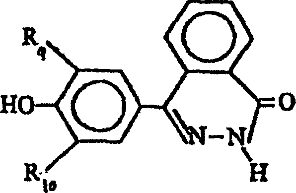
Applications Claiming Priority (5)
| Application Number | Priority Date | Filing Date | Title |
|---|---|---|---|
| CN01113257 | 2001-07-05 | ||
| CNB011132574A CN1161397C (en) | 2001-07-05 | 2001-07-05 | Polydiquinoline ketonic ether ketone with pendant sulfonate radical and its prepn. |
| CN 02111491 CN1200029C (en) | 2002-04-25 | 2002-04-25 | Polyphthalazone with sulfosalt lateral group and its preparation method |
| CN02111491 | 2002-04-25 | ||
| PCT/US2002/021346 WO2003005474A2 (en) | 2001-07-05 | 2002-07-05 | Ionomer for use in fuel cells and method of making same |
Publications (2)
| Publication Number | Publication Date |
|---|---|
| DE60223539D1 DE60223539D1 (en) | 2007-12-27 |
| DE60223539T2 true DE60223539T2 (en) | 2008-09-25 |
Family
ID=25740356
Family Applications (1)
| Application Number | Title | Priority Date | Filing Date |
|---|---|---|---|
| DE60223539T Expired - Lifetime DE60223539T2 (en) | 2001-07-05 | 2002-07-05 | IONOMER FOR USE IN FUEL CELLS AND METHOD OF MANUFACTURING THE SAME |
Country Status (10)
| Country | Link |
|---|---|
| US (1) | US7405015B2 (en) |
| EP (1) | EP1402590B1 (en) |
| JP (1) | JP4102299B2 (en) |
| KR (1) | KR100817691B1 (en) |
| AU (1) | AU2002354786B2 (en) |
| BR (1) | BR0210803B1 (en) |
| CA (1) | CA2451896C (en) |
| DE (1) | DE60223539T2 (en) |
| RU (1) | RU2004103077A (en) |
| WO (1) | WO2003005474A2 (en) |
Cited By (1)
| Publication number | Priority date | Publication date | Assignee | Title |
|---|---|---|---|---|
| US8785060B2 (en) | 2006-11-02 | 2014-07-22 | Hyundai Motor Company | Method of manufacturing multilayer electrolyte reinforced composite membrane |
Families Citing this family (18)
| Publication number | Priority date | Publication date | Assignee | Title |
|---|---|---|---|---|
| US7297429B2 (en) | 2002-07-05 | 2007-11-20 | Gore Enterprise Holdings, Inc. | Ionomer for use in fuel cells and method of making same |
| JP2005133092A (en) * | 2003-10-10 | 2005-05-26 | Hitachi Chem Co Ltd | Polymer electrolyte compound having heterocycle, polymer electrolyte membrane, catalyst layer-forming electrolyte membrane using it and electrochemical device using it |
| JP2006135022A (en) * | 2004-11-04 | 2006-05-25 | Nitto Denko Corp | Wiring circuit board |
| KR100614100B1 (en) * | 2005-01-14 | 2006-08-22 | 한국과학기술연구원 | Method for preparing the membrane-electrode assembly for fuel cell using membrane on electrode method before the dry-out of nafion ionomer solution and membrane-electrode assembly for fuel cell prepared by the method |
| TWI543201B (en) * | 2005-02-15 | 2016-07-21 | 東麗股份有限公司 | Polymer electrolyte molded body, polymer electrolyte part, membrane electrode complex, and polymer electrolyte type fuel cell |
| US20060199059A1 (en) * | 2005-03-01 | 2006-09-07 | Xu Helen X | Ion conductive polymer electrolyte and its membrane electrode assembly |
| EP1855339B1 (en) * | 2005-03-04 | 2012-01-04 | Ube Industries, Ltd. | Novel polymer electrolyte, polymer electrolyte composition, electrolyte membrane, and production method and use thereof |
| JP2006338928A (en) * | 2005-05-31 | 2006-12-14 | Hitachi Chem Co Ltd | Reinforced polyelectrolyte, electrode-polyelectrolyte membrane assembly, and fuel cell as well as method of manufacturing them |
| KR100833056B1 (en) | 2006-03-31 | 2008-05-27 | 주식회사 엘지화학 | Reinforced composite electrolyte membrane for fuel cell |
| KR100851924B1 (en) | 2007-02-01 | 2008-08-12 | 충주대학교 산학협력단 | Multi-sulfonated poly aryl ether ketone copolymer and electrolyte membrane using the same |
| DE102007008268B4 (en) * | 2007-02-20 | 2009-02-19 | Staxera Gmbh | Test bench and test procedure for a fuel cell stack |
| CN102318121B (en) * | 2008-12-22 | 2015-04-08 | 3M创新有限公司 | Fuel cell membrane electrode assembly with multilayer cathode |
| KR101651093B1 (en) * | 2009-12-11 | 2016-08-26 | 건국대학교 글로컬산학협력단 | Multi-sulfonated multi-phenyl units contained proton exchange membrane |
| US9005841B2 (en) * | 2009-12-18 | 2015-04-14 | Lg Chem, Ltd. | Polymer electrolyte membrane for fuel cell, membrane electrode assembly and fuel cell including the same |
| US20110274990A1 (en) * | 2010-05-07 | 2011-11-10 | Yang G Xu | Methanol and Hydrogen Peroxide Fuel Cell with Hydroxyl Ion Exchange Membrane |
| US9385388B2 (en) * | 2011-06-16 | 2016-07-05 | Lg Chem, Ltd. | Polymer electrolyte membrane for fuel cell, membrane electrode assembly and fuel cell including the same |
| US10603639B2 (en) | 2016-09-02 | 2020-03-31 | Hossein Beydaghi | Nanocomposite blend membrane |
| WO2023139040A1 (en) | 2022-01-21 | 2023-07-27 | Basf Se | Mixed platinum ruthenium oxide and electrodes for the oxygen evolution reaction |
Family Cites Families (24)
| Publication number | Priority date | Publication date | Assignee | Title |
|---|---|---|---|---|
| US3282875A (en) * | 1964-07-22 | 1966-11-01 | Du Pont | Fluorocarbon vinyl ether polymers |
| CA962021A (en) * | 1970-05-21 | 1975-02-04 | Robert W. Gore | Porous products and process therefor |
| US4083768A (en) * | 1976-05-24 | 1978-04-11 | Allied Chemical Corporation | Preparation of high performance polyelectrolyte membrane |
| DE2861696D1 (en) * | 1977-09-07 | 1982-04-29 | Ici Plc | Thermoplastic aromatic polyetherketones, a method for their preparation and their application as electrical insulants |
| US4358545A (en) * | 1980-06-11 | 1982-11-09 | The Dow Chemical Company | Sulfonic acid electrolytic cell having flourinated polymer membrane with hydration product less than 22,000 |
| US4940525A (en) * | 1987-05-08 | 1990-07-10 | The Dow Chemical Company | Low equivalent weight sulfonic fluoropolymers |
| USRE37707E1 (en) * | 1990-02-22 | 2002-05-21 | Stmicroelectronics S.R.L. | Leadframe with heat dissipator connected to S-shaped fingers |
| US5306789A (en) * | 1990-10-31 | 1994-04-26 | Hay Allan S | Amorphous, soluble, aromatic polymers with high glass transition temperatures |
| US5237062A (en) * | 1992-04-28 | 1993-08-17 | Hay Allan S | Polymers derived from phenolphthaleins |
| US5254663A (en) * | 1992-04-28 | 1993-10-19 | Hay Allan S | Polymers derived from phenolphthaleins |
| US5834523A (en) * | 1993-09-21 | 1998-11-10 | Ballard Power Systems, Inc. | Substituted α,β,β-trifluorostyrene-based composite membranes |
| USRE37756E1 (en) * | 1994-06-29 | 2002-06-18 | Jiann H. Chen | Fuser members overcoated with fluorocarbon elastomer containing aluminum oxide |
| US5525436A (en) * | 1994-11-01 | 1996-06-11 | Case Western Reserve University | Proton conducting polymers used as membranes |
| USRE37701E1 (en) * | 1994-11-14 | 2002-05-14 | W. L. Gore & Associates, Inc. | Integral composite membrane |
| US5547551A (en) * | 1995-03-15 | 1996-08-20 | W. L. Gore & Associates, Inc. | Ultra-thin integral composite membrane |
| US5882810A (en) * | 1996-03-08 | 1999-03-16 | The Dow Chemicalcompany | Active layer for membrane electrode assembly |
| US5716727A (en) * | 1996-04-01 | 1998-02-10 | Case Western Reserve University | Proton conducting polymers prepared by direct acid casting |
| JP3861367B2 (en) * | 1996-04-18 | 2006-12-20 | 住友化学株式会社 | POLYMER ELECTROLYTE, MANUFACTURING METHOD THEREOF, AND FUEL CELL COMPRISING THE SAME |
| US6444343B1 (en) | 1996-11-18 | 2002-09-03 | University Of Southern California | Polymer electrolyte membranes for use in fuel cells |
| US6399254B1 (en) * | 1997-05-23 | 2002-06-04 | Dai-Ichi Kogyo Seiyaku Co., Ltd. | Solid electrolyte |
| US6365294B1 (en) * | 1999-04-30 | 2002-04-02 | The Administrators Of The Tulane Educational Fund | Sulfonated polyphosphazenes for proton-exchange membrane fuel cells |
| WO2000077874A1 (en) | 1999-06-11 | 2000-12-21 | The Penn State Research Foundation | Proton conducting polymer membranes |
| WO2002025764A1 (en) | 2000-09-20 | 2002-03-28 | Virginia Tech Intellectual Properties, Inc. | Ion-conducting sulfonated polymeric materials |
| US7297429B2 (en) * | 2002-07-05 | 2007-11-20 | Gore Enterprise Holdings, Inc. | Ionomer for use in fuel cells and method of making same |
-
2002
- 2002-07-05 BR BRPI0210803-8A patent/BR0210803B1/en not_active IP Right Cessation
- 2002-07-05 JP JP2003511332A patent/JP4102299B2/en not_active Expired - Fee Related
- 2002-07-05 KR KR1020047000040A patent/KR100817691B1/en not_active IP Right Cessation
- 2002-07-05 RU RU2004103077/04A patent/RU2004103077A/en not_active Application Discontinuation
- 2002-07-05 WO PCT/US2002/021346 patent/WO2003005474A2/en active IP Right Grant
- 2002-07-05 US US10/481,226 patent/US7405015B2/en not_active Expired - Fee Related
- 2002-07-05 DE DE60223539T patent/DE60223539T2/en not_active Expired - Lifetime
- 2002-07-05 AU AU2002354786A patent/AU2002354786B2/en not_active Ceased
- 2002-07-05 CA CA002451896A patent/CA2451896C/en not_active Expired - Fee Related
- 2002-07-05 EP EP02752181A patent/EP1402590B1/en not_active Expired - Fee Related
Cited By (2)
| Publication number | Priority date | Publication date | Assignee | Title |
|---|---|---|---|---|
| US8785060B2 (en) | 2006-11-02 | 2014-07-22 | Hyundai Motor Company | Method of manufacturing multilayer electrolyte reinforced composite membrane |
| DE102007003162B4 (en) * | 2006-11-02 | 2017-11-02 | Hyundai Motor Co. | Process for producing a multilayer electrolyte-reinforced composite membrane |
Also Published As
| Publication number | Publication date |
|---|---|
| BR0210803A (en) | 2004-06-29 |
| EP1402590B1 (en) | 2007-11-14 |
| JP2004534890A (en) | 2004-11-18 |
| WO2003005474A3 (en) | 2003-08-28 |
| DE60223539D1 (en) | 2007-12-27 |
| RU2004103077A (en) | 2005-03-27 |
| EP1402590A2 (en) | 2004-03-31 |
| US20050079399A1 (en) | 2005-04-14 |
| KR20040013094A (en) | 2004-02-11 |
| WO2003005474A9 (en) | 2004-07-01 |
| KR100817691B1 (en) | 2008-03-27 |
| JP4102299B2 (en) | 2008-06-18 |
| BR0210803B1 (en) | 2011-11-29 |
| US7405015B2 (en) | 2008-07-29 |
| AU2002354786B2 (en) | 2005-08-18 |
| WO2003005474A2 (en) | 2003-01-16 |
| CA2451896A1 (en) | 2003-01-16 |
| CA2451896C (en) | 2009-09-08 |
Similar Documents
| Publication | Publication Date | Title |
|---|---|---|
| DE60223539T2 (en) | IONOMER FOR USE IN FUEL CELLS AND METHOD OF MANUFACTURING THE SAME | |
| DE102010035357B4 (en) | Process for the preparation of an ion exchange membrane with lamellar morphology | |
| DE112004001057B4 (en) | High strength polymer electrolyte membrane, process for its preparation and use | |
| JP4598335B2 (en) | Improved polymer electrolyte membranes formed from mixed dispersions | |
| DE60020915T2 (en) | Polymer composite membrane and process for its preparation | |
| EP1506591B1 (en) | Polymer electrolyte membrane, method for the production thereof, and application thereof in fuel cells | |
| DE60221429T2 (en) | IONOMER WITH LOW EQUIVALENT WEIGHT | |
| DE602006000505T2 (en) | Catalyst-coated membrane composite | |
| EP1971635B1 (en) | Proton-conducting polymer membrane | |
| US7297429B2 (en) | Ionomer for use in fuel cells and method of making same | |
| DE10296922T5 (en) | Electrode structure for polymer electrolyte fuel cells, method of manufacturing the same and polymer electrolyte fuel cell | |
| DE10309135A1 (en) | Process for the preparation of a polymer system capable of proton exchange based on polyaryl ether ketones | |
| DE102012212420A1 (en) | Laminated structure membrane and orientation controlled nanofiber reinforcing additives for fuel cells | |
| AU2002354786A1 (en) | Ionomer for use in fuel cells and method of making same | |
| DE102008043936A1 (en) | Reinforced composite membrane for polymer electrolyte fuel cell | |
| DE10296598T5 (en) | Fuel cell with polymer electrolyte | |
| DE102010056453A1 (en) | Method for reducing the chemical degradation of a fuel cell | |
| DE102008008097A1 (en) | Crosslinked aromatic polymer electrolyte diaphragm for use in polymer electrolyte gas cell, has aromatic polymer film substrate, which has aromatic rings where groups of sulphonic acid are introduced | |
| DE10318398B4 (en) | A method of manufacturing an electrolyte membrane composite electrode and a paint composition used therein | |
| DE102015121787B4 (en) | Grafted functional groups on expanded tetrafluoroethylene (ePTFE) supports for fuel cell and water transport membranes | |
| DE60212209T2 (en) | FUEL CELL AND MEMBRANE ELECTRODE ASSEMBLY FOR THIS | |
| DE102009001137A1 (en) | Polymer electrolyte membrane for fuel cells, comprises a polymer component, an electrolyte mixture, and additive components for increasing proton conductivity of the membrane and for influencing its mechanical- and/or surfaces properties | |
| WO2011020872A1 (en) | Long-term stable polymer electrolyte membrane for ht fuel cells and method for the production thereof | |
| DE102009001141A1 (en) | Producing polymer electrolyte membrane, by producing polymer solution of polyazol in solvent mixture, transferring polymer solution in flat structure, and dropping polymer solution that is transferred in flat structure with liquid water | |
| DE102004055129A1 (en) | Production of polymer electrolyte membrane for fuel cells based on liquid electrolyte containing polymer |
Legal Events
| Date | Code | Title | Description |
|---|---|---|---|
| 8364 | No opposition during term of opposition |