HINTERGRUND DER ERFINDUNGBACKGROUND OF THE INVENTION
1. Gebiet der Erfindung1. Field of the invention
Die vorliegende Erfindung bezieht sich auf ein Teilchenstrahlbehandlungssystem und insbesondere auf ein Teilchenstrahlbestrahlungsgerät zur Behandlung eines betroffenen Körperteils durch Bestrahlung mit geladenen Teilchenstrahlen mit Protonen, Kohlenstoffionen oder dergleichen.The present invention relates to a particle beam treatment system, and more particularly to a particle beam irradiation apparatus for treating an affected body part by irradiation with charged particle beams having protons, carbon ions or the like.
2. Beschreibung des Stands der Technik2. Description of the Related Art
Ein Behandlungsverfahren zur Behandlung eines Patienten mit Krebs oder dergleichen durch Bestrahlen des betroffenen Körperteils des Patienten mit geladenen Teilchenstrahlen wie etwa Protonenstrahlen ist bekannt. Das für diese Behandlung benutzte Behandlungssystem umfasst eine Erzeugungseinheit für geladene Teilchenstrahlen, ein Strahltransportsystem und einen Behandlungsraum. Der durch den Beschleuniger der Erzeugungseinheit für geladene Teilchenstrahlen beschleunigte geladene Teilchenstrahl erreicht das Strahlausgabegerät im Behandlungsraum durch das Strahltransportsystem, und nach Abtasten mit den Abtastelektromagneten im Strahlausgabegerät wird der geladene Teilchenstrahl aus einer Düse auf den betroffenen Körperteil des Patienten gelenkt. Ein Behandlungsverfahren unter Verwendung eines solchen Behandlungssystems ist bekannt, das die folgenden Schritte aufweist: Unterbrechen der Ausstrahlung des geladenen Teilchenstrahls aus dem Strahlausgabegerät, und, in einem Zustand, in dem die Ausstrahlung des geladenen Teilchenstrahls unterbrochen ist, Steuern der Abtastelektromagnete, um die Bestrahlungsposition (den Punkt oder Spot) für den geladenen Teilchenstrahl zu ändern (als „Abtastung” bezeichnet) und die Ausstrahlung des geladenen Teilchenstrahls aus dem Strahlausgabegerät nach der Änderung zu beginnen (siehe zum Beispiel die Europäische Patentanmeldung Nr. 0779081 A2 [1 und dergleichen]).A treatment method for treating a patient with cancer or the like by irradiating the affected body part of the patient with charged particle beams such as proton beams is known. The treatment system used for this treatment comprises a charged particle beam generation unit, a jet transport system, and a treatment room. The charged particle beam accelerated by the accelerator of the charged particle generation unit reaches the jet output device in the treatment space through the beam transport system, and after scanning with the scanning electromagnets in the jet output device, the charged particle beam is directed from a nozzle to the affected body part of the patient. A treatment method using such a treatment system is known, comprising the steps of: stopping the radiation of the charged particle beam from the jet output device, and, in a state in which the radiation of the charged particle beam is interrupted, controlling the scanning electromagnets to the irradiation position (FIG. the point or spot) for the charged particle beam (referred to as "sampling") and to start the radiation of the charged particle beam from the jet output device after the change (see, for example, US Pat European Patent Application No. 0779081 A2 [ 1 and the same]).
In dem vorstehend beschriebenen herkömmlichen Teilchenstrahlbehandlungssystem weist das Strahlausgabegerät, um die Strahlenexposition für gesundes Gewebe auf ein Minimum zu reduzieren und eine ordnungsgemäße Behandlung mit weder zu hoher noch zu geringer Bestrahlung durchzuführen, einen Bestrahlungsdosismonitor und/oder einen Strahlpositionsmonitor zum Abschätzen der Bestrahlungsdosisverteilung auf, der auf der stromabwärtigen Seite der Elektromagneten und unmittelbar vor einem zu bestrahlenden Patienten angeordnet ist. In vielen Fällen ist dieser Monitor von einem Typ, der die durch das Hindurchtreten von Strahlen ionisierten Ladungen in einem Kondensator speichert und die durch den Kondensator nach der Punktbestrahlung induzierte Spannung erfasst. Die Kapazität dieses Kondensators wird so bestimmt, dass er den Betrag der durch den Punkt, der der höchsten Bestrahlungsdosis ausgesetzt ist, ionisierten Ladungen zulässt.In the conventional particle beam treatment system described above, in order to minimize the radiation exposure to healthy tissue and to perform proper treatment with neither too high nor too little irradiation, the jet output apparatus has an irradiation dose monitor and / or a beam position monitor for estimating the irradiation dose distribution the downstream side of the electromagnet and immediately before a patient to be irradiated is arranged. In many cases, this monitor is of a type which stores the charges ionized by the passage of rays in a capacitor and detects the voltage induced by the capacitor after the spot irradiation. The capacitance of this capacitor is determined so as to allow the amount of charges ionized by the point exposed to the highest irradiation dose.
Bei dem vorstehend beschriebenen Kondensator steigt mit abnehmender Kapazität die Ausgangsspannung, wodurch sich die Auflösung erhöht. Umgekehrt nimmt die Auflösung mit zunehmender Kapazität des Kondensators ab. In Anbetracht dieser Situation könnte, wenn die Differenz bezüglich der Bestrahlungsdosis zwischen dem Punkt, der der höchsten Bestrahlungsdosis ausgesetzt ist, und dem Punkt, der der niedrigsten Bestrahlungsdosis ausgesetzt ist, verringert werden kann, die Kapazität des Kondensators entsprechend verringert werden, um die Auflösung zu verbessern. Dies würde die Möglichkeit bieten, die tatsächliche Bestrahlungsdosis genauer zu erfassen. Bei der vorstehend erwähnten herkömmlichen Technik wird der vorstehend beschriebenen Verringerung der Differenz der Bestrahlungsdosis keine besondere Beachtung geschenkt, was Raum für eine Verbesserung der Messgenauigkeit im Hinblick auf die tatsächliche Bestrahlungsdosis lässt.In the capacitor described above, as the capacitance decreases, the output voltage increases, thereby increasing the resolution. Conversely, the resolution decreases with increasing capacitance of the capacitor. In view of this situation, if the difference in irradiation dose between the point exposed to the highest irradiation dose and the point exposed to the lowest irradiation dose can be reduced, the capacitance of the capacitor could be correspondingly reduced to increase the resolution improve. This would provide the opportunity to more accurately capture the actual radiation dose. In the above-mentioned conventional technique, no particular consideration is given to the above-described reduction in the difference of the irradiation dose, leaving room for improvement of the measurement accuracy with respect to the actual irradiation dose.
Bei der Durchführung der Bestrahlung jedes einzelnen Punktes wird Punkt für Punkt eine Soll-Bestrahlungsdosis eingestellt. Sobald ein integrierter Wert der mit dem Bestrahlungsdosismonitor gemessenen Bestrahlungsdosis den Sollwert erreicht hat, wird ein Strahlunterbrechungsbefehl an den Beschleuniger ausgegeben, und in Reaktion darauf unterbricht der Beschleuniger die Ausstrahlung eines geladenen Teilchenstrahls. Bei typischen Beschleunigern wie etwa einem Slow-Cycling-Synchrotron oder einem Zyklotron, ist es, selbst wenn der Strahlunterbrechungsbefehl wie vorstehend beschrieben eingegeben wird, streng genommen möglich, dass es zu einer gewissen Reaktionsverzögerung kommt, anstatt die Ausstrahlung des geladenen Teilchenstrahls sofort zu unterbrechen. In einem solchen Fall wird der geladene Teilchenstrahl auch nach Erreichen des vorstehend genannten Sollwerts für den Zeitraum während der Reaktionsverzögerungszeit weiter auf den betreffenden Punkt abgestrahlt. Dies lässt Raum für eine Verbesserung der Steuerungsgenauigkeit im Hinblick auf die Bestrahlungsdosis des geladenen Teilchenstrahls.When performing the irradiation of each individual point, a target irradiation dose is set point by point. Once an integrated value of the dose of radiation measured by the radiation dose monitor has reached the set point, a beam interrupt command is issued to the accelerator, and in response, the accelerator interrupts the emission of a charged particle beam. In typical accelerators, such as a slow cycling synchrotron or a cyclotron, even if the beam interrupt command is input as described above, strictly speaking, it is possible for some response delay to occur instead of immediately interrupting the radiation of the charged particle beam. In such a case, even after reaching the above-mentioned target value for the period during the reaction delay time, the charged particle beam is further radiated to the subject point. This leaves room for improving the control accuracy with respect to the irradiation dose of the charged particle beam.
Weil der Bestrahlungsdosismonitor eine Maschine ist, kann die Möglichkeit, dass der Bestrahlungsdosismonitor eine Störung oder einen Fehler verursacht, nicht vollkommen ausgeschlossen werden. Weil die Soll-Bestrahlungsdosis für jeden einzelnen Punkt im Allgemeinen ein Wert ist, der aus einer Datenbank übermittelt wird, oder ein Wert, der aus dem übermittelten Wert berechnet wird, ist es außerdem möglich, dass in der Phase der Übermittlung oder der Berechnung ein falscher Wert eingegeben wird. Bei der vorstehend beschriebenen herkömmlichen Technik wird einer solchen Monitorstörung oder einem solchen Eingabefehler jedoch keine besondere Beachtung geschenkt. Dies lässt Raum für eine Verbesserung hinsichtlich der Verhinderung einer übermäßigen Ausstrahlung von geladenen Teilchenstrahlen aufgrund der vorstehend genannten Monitorstörung oder eines Eingabefehlers.Because the irradiation dose monitor is a machine, the possibility that the irradiation dose monitor will cause a disturbance or an error can not be completely eliminated. In addition, because the target irradiation dose for each individual point is generally a value transmitted from a database or a value calculated from the transmitted value, it is also possible that at the point of transmission or the calculation is entered a wrong value. In the conventional technique described above, however, no special consideration is given to such a monitor disturbance or input error. This leaves room for improvement in preventing excessive radiation of charged particle beams due to the above-mentioned monitor noise or input error.
Weiter wird bei der Durchführung der Bestrahlung jedes einzelnen Punktes Punkt für Punkt eine Soll-Bestrahlungsdosis eingestellt. Sobald der integrierte Wert der mit dem Bestrahlungsdosismonitor gemessenen Bestrahlungsdosis den Sollwert erreicht hat, wird ein Strahlunterbrechungsbefehl an den Beschleuniger ausgegeben, und in Reaktion darauf unterbricht der Beschleuniger die Ausstrahlung des geladenen Teilchenstrahls. Bezüglich einer solchen Strahlunterbrechungsfunktion ist es auch möglich, dass die mit dieser Funktion verbundene Ausrüstung eine Störung oder einen Fehler verursacht. Bei der vorstehend beschriebenen herkömmlichen Technik wird einer Störung einer solchen Strahlunterbrechungsfunktion jedoch keine besondere Beachtung geschenkt. Dies lässt Raum für eine Verbesserung hinsichtlich der Verhinderung einer übermäßigen Ausstrahlung von geladenen Teilchenstrahlen aufgrund der vorstehend beschriebenen Störung oder des Ausfalls der Strahlunterbrechungsfunktion.Further, in carrying out the irradiation of each individual point, a target irradiation dose is set point by point. As soon as the integrated value of the irradiation dose measured with the irradiation dose monitor has reached the target value, a beam interruption command is issued to the accelerator, and in response the accelerator interrupts the irradiation of the charged particle beam. With respect to such a beam interrupting function, it is also possible that the equipment associated with this function causes a disturbance or an error. In the conventional technique described above, however, no special consideration is given to disturbing such a beam interrupting function. This leaves room for improvement in the prevention of excessive radiation of charged particle beams due to the above-described disturbance or the failure of the beam-interrupting function.
In dem Beitrag „Magnetic scanning system for heavy ion therapy”, Nuclear Instruments & Methods in Physics Research, A330 (1993), Nr. 1/2, Seiten 296 bis 305, beschreiben Haberer et al. ein Bestrahlungsverfahren mit den Merkmalen des Oberbegriffs nach dem anliegenden Anspruch 1.In the article "Magnetic scanning system for heavy ion therapy", Nuclear Instruments & Methods in Physics Research, A330 (1993), No. 1/2, pages 296 to 305, Haberer et al. an irradiation method having the features of the preamble according to the appended claim 1.
Ziel der vorliegenden Erfindung ist die Bereitstellung eines Teilchenstrahlbestrahlungsgeräts, das in der Lage ist, die Messgenauigkeit im Hinblick auf die tatsächliche Bestrahlungsdosis bei der Behandlung mit geladenen Teilchenstrahlen zu verbessern.The object of the present invention is to provide a particle beam irradiation apparatus capable of improving the measurement accuracy with respect to the actual irradiation dose in the charged particle beam treatment.
Weiterhin ist es erwünscht, ein Teilchenstrahlbestrahlungsgerät bereitzustellen, das in der Lage ist, die Steuerungsgenauigkeit im Hinblick auf die Bestrahlungsdosis der geladenen Teilchenstrahlen zu verbessern.Further, it is desirable to provide a particle beam irradiation apparatus capable of improving the control accuracy with respect to the irradiation dose of the charged particle beams.
Weiterhin ist es erwünscht, ein Teilchenstrahlbestrahlungsgerät bereitzustellen, das in der Lage ist, die übermäßige Ausstrahlung von geladenen Teilchenstrahlen aufgrund einer Monitorstörung, eines Eingabefehlers oder dergleichen zuverlässig zu verhindern.Further, it is desirable to provide a particle beam irradiation apparatus capable of reliably preventing the excessive radiation of charged particle beams due to a monitor disturbance, an input error, or the like.
Weiterhin ist es erwünscht, ein Teilchenstrahlbestrahlungsgerät bereitzustellen, das in der Lage ist, die übermäßige Ausstrahlung von geladenen Teilchenstrahlen aufgrund einer Störung oder dergleichen in einer Strahlunterbrechungsfunktion zuverlässig zu verhindern.Further, it is desirable to provide a particle beam irradiation apparatus capable of reliably preventing the excessive radiation of charged particle beams due to a disturbance or the like in a beam interruption function.
Weiterhin ist es erwünscht, ein Teilchenstrahlbestrah-lungsgerät bereitzustellen, das in der Lage ist, die Behandlungszeit bei der Durchführung der Bestrahlung mit geladenen Teilchenstrahlen für jeden von mehreren Schichtbereichen in einem Target zu verkürzen.Further, it is desirable to provide a particle beam irradiation apparatus capable of shortening the treatment time in carrying out the charged particle beam irradiation for each of a plurality of layer areas in a target.
ZUSAMMENFASSUNG DER ERFINDUNGSUMMARY OF THE INVENTION
Zur Erreichung der vorstehend beschriebenen Ziele stellt die vorliegende Erfindung ein Teilchenstrahlbestrahlungsgerät nach der Definition in Anspruch 1 bereit.To achieve the objects described above, the present invention provides a particle beam irradiation apparatus as defined in claim 1.
Die Steuereinheit steuert die geladene TeilchenstrahlAbtasteinheit zur mehrfachen Durchführung von Bestrahlungen mit geladenen Teilchenstrahlen in Bezug auf wenigstens eine Bestrahlungsposition. Aufgrund dieser Funktion ist es bezüglich einer Bestrahlungsposition, die durch eine einmalige Ionenbestrahlung einer zu hohen Bestrahlungsdosis ausgesetzt ist, möglich, eine unterteilte Bestrahlung durchzuführen, um die Bestrahlungsdosis für jede einzelne Bestrahlung zu verringern. Dies ermöglicht es, die Differenz bezüglich der Bestrahlungsdosis zwischen der Bestrahlungsposition, die der höchsten Dosis ausgesetzt ist, und der, die der geringsten Dosis ausgesetzt ist, zu verringern, wodurch die Bestrahlungsdosis angeglichen wird. Folglich kann die Kapazität des Kondensators eines Positionsmonitors entsprechend verringert werden, um die Auflösung zu verbessern, und daher kann die tatsächliche Bestrahlungsdosis bei der Behandlung weiter richtig erfasst werden.The control unit controls the charged particle beam scanning unit to repeatedly perform charged particle beam irradiations with respect to at least one irradiation position. Due to this function, with respect to an irradiation position exposed by a single ion irradiation of too high an irradiation dose, it is possible to perform a subdivided irradiation to reduce the irradiation dose for each irradiation. This makes it possible to reduce the difference in the irradiation dose between the irradiation position which is exposed to the highest dose and that which is exposed to the lowest dose, whereby the irradiation dose is equalized. Consequently, the capacitance of the capacitor of a position monitor can be correspondingly reduced to improve the resolution, and therefore, the actual irradiation dose in the treatment can be further properly detected.
Die Unteransprüche beziehen sich auf bevorzugte Ausführungsformen.The subclaims relate to preferred embodiments.
Das Teilchenstrahlbestrahlungsgerät weist eine Steuereinheit auf, die die Ausstrahlung des geladenen Teilchenstrahls auf die Bestrahlungsposition so steuert, dass die auf die Bestrahlungsposition einwirkende Bestrahlungsdosis eine eingestellte Bestrahlungsdosis wird, in einem Zustand, in dem die auf die Bestrahlungsposition einwirkende Bestrahlungsdosis während des Zeitraums von der Ausgabe eines Strahlextraktions-Unterbrechungssignals zu dem Zeitpunkt, an dem die mit dem Bestrahlungsdosisdetektor gemessene Bestrahlungsdosis die eingestellte Bestrahlungsdosis erreicht, bis zur Extraktionsunterbrechung des geladenen Teilchenstrahls aus dem Beschleuniger addiert wird.The particle beam irradiation apparatus has a control unit that controls the irradiation of the charged particle beam to the irradiation position such that the irradiation dose applied to the irradiation position becomes a set irradiation dose in a state where the irradiation dose applied to the irradiation position during the period from the issuance of an irradiation position The beam extraction interrupt signal at the time when the irradiation dose measured by the irradiation dose detector reaches the set irradiation dose is added to the extraction interruption of the charged particle beam from the accelerator.
Auch wenn der Strahlunterbrechungsbefehl eingegeben wird, ist es genau genommen möglich, dass es zu einer gewissen Reaktionsverzögerung kommt, anstatt die Extraktion des geladenen Teilchenstrahls aus dem Beschleuniger sofort zu unterbrechen.In fact, even if the beam interrupt command is input, it is possible for it to give some response delay instead of immediately interrupting the extraction of the charged particle beam from the accelerator.
Die Steuereinheit kann eine Bestrahlung mit dem geladenen Teilchenstrahl an einer Bestrahlungsposition so durchführen, dass die Bestrahlungsdosis an der Bestrahlungsposition eine eingestellte Bestrahlungsdosis wird, in einem Zustand, in dem die auf die Bestrahlungsposition einwirkende Bestrahlungsdosis während des Zeitraums von der Ausgabe eines Strahlextraktions-Unterbrechungssignals bis zur Extraktionsunterbrechung des geladenen Teilchenstrahls aus dem Beschleuniger addiert wird. Dadurch kann die Bestrahlungsdosis an jeder Bestrahlungsposition im Wesentlichen die eingestellte Bestrahlungsdosis erreichen, wodurch es möglich ist, jede Bestrahlungsposition mit hoher Genauigkeit mit dem geladenen Teilchenstrahl zu bestrahlen. Zur Steuerung der Bestrahlungsdosis kann, auch wenn eine Zeitverzögerung zwischen der Ausgabe des Strahlextraktions-Unterbrechungssignals und der Extraktionsunterbrechung des geladenen Teilchenstrahls aus dem Beschleuniger eintritt, die Bestrahlungsdosis an jeder Bestrahlungsposition auf eine eingestellte Bestrahlungsdosis geändert werden, wobei die Bestrahlungsdosis für den Zeitraum während der Zeitverzögerung berücksichtigt wird. Dadurch ist es möglich, jede Bestrahlungsposition mit einem hohen Maß an Genauigkeit mit geladenen Teilchenstrahlen mit einer Dosis zu bestrahlen, die im Wesentlichen gleich der eingestellten Bestrahlungsdosis ist.The control unit may irradiate the charged particle beam at an irradiation position so that the irradiation dose at the irradiation position becomes a set irradiation dose in a state in which the irradiation dose applied to the irradiation position during the period from the output of a beam extraction interrupt signal to the irradiation position Extraction interruption of the charged particle beam is added from the accelerator. Thereby, the irradiation dose at each irradiation position can substantially reach the set irradiation dose, whereby it is possible to irradiate each irradiation position with high accuracy with the charged particle beam. For controlling the irradiation dose, even if a time lag occurs between the output of the beam extraction interruption signal and the extraction burst of the charged particle beam from the accelerator, the irradiation dose at each irradiation position may be changed to a set irradiation dose, taking into consideration the irradiation dose for the period during the time delay becomes. Thereby, it is possible to irradiate each irradiation position with a high degree of accuracy with charged particle beams at a dose substantially equal to the set irradiation dose.
Die Steuereinheit unterbricht die Ausstrahlung des geladenen Teilchenstrahls aus dem Strahlausgabegerät, das, in einem Zustand, in dem die Ausstrahlung des geladenen Teilchenstrahls unterbrochen ist, die geladene Teilchenstrahl-Abtasteinheit so steuert, dass die Bestrahlungsposition des geladenen Teilchenstrahls geändert wird und die Ausstrahlung des geladenen Teilchenstrahls aus dem Strahlausgabegerät nach der vorstehend beschriebenen Änderung begonnen wird, und das Auftreten einer Anomalie auf der Grundlage der verstrichenen Zeit vom Beginn der Ausstrahlung des geladenen Teilchenstrahls in Bezug auf eine Bestrahlungsposition bestimmt.The control unit stops the radiation of the charged particle beam from the jet output apparatus which, in a state in which the radiation of the charged particle beam is interrupted, controls the charged particle beam scanning unit to change the irradiation position of the charged particle beam and the radiation of the charged particle beam is started from the jet output apparatus after the above-described change, and determines the occurrence of an anomaly on the basis of the elapsed time from the start of the irradiation of the charged particle beam with respect to an irradiation position.
Die Steuereinheit bestimmt das Auftreten einer Anomalie auf der Grundlage der verstrichenen Zeit vom Beginn der Ausstrahlung des geladenen Teilchenstrahls in Bezug auf eine Bestrahlungsposition. Daher kann, selbst wenn die Bestrahlungszeit des geladenen Teilchenstrahls aufgrund des Auftretens einer Störung oder eines Fehlers des Bestrahlungsdosisdetektors oder eines falschen Eingabewertes vermutlich anomal verlängert wird, die Ausstrahlung des geladenen Teilchenstrahls nach Ablauf einer bestimmten Zeit unterbrochen werden. Dies verhindert zuverlässig eine übermäßige Bestrahlung eines Targets und trägt weiter zur Erhöhung der Sicherheit bei.The control unit determines the occurrence of an abnormality on the basis of the elapsed time from the start of the irradiation of the charged particle beam with respect to an irradiation position. Therefore, even if the irradiation time of the charged particle beam is likely to be abnormally prolonged due to the occurrence of a disturbance or an error of the irradiation dose detector or an erroneous input value, the irradiation of the charged particle beam may be interrupted after a lapse of a certain time. This reliably prevents excessive irradiation of a target and further contributes to the increase in safety.
Weiter unterbricht die Steuereinheit die Ausstrahlung des geladenen Teilchenstrahls aus dem Strahlausgabegerät, das, in einem Zustand, in dem die Ausstrahlung des geladenen Teilchenstrahls unterbrochen ist, die geladene Teilchenstrahl-Abtasteinheit so steuert, dass die Bestrahlungsposition des geladenen Teilchenstrahls geändert wird und die Ausstrahlung des geladenen Teilchenstrahls aus dem Strahlausgabegerät nach der vorstehend beschriebenen Änderung begonnen wird, und das Auftreten einer Anomalie anhand der mit dem Bestrahlungsdosisdetektor gemessenen Bestrahlungsdosis und einer zweiten eingestellten Bestrahlungsdosis bestimmt, die größer als die jeweils ersten eingestellten Bestrahlungsdosen ist, im Hinblick auf mehrere Bestrahlungspositionen in dem Target.Further, the control unit stops the radiation of the charged particle beam from the jet output apparatus which, in a state in which the radiation of the charged particle beam is interrupted, controls the charged particle beam scanning unit to change the irradiation position of the charged particle beam and the radiation of the charged one Particle beam is started from the beam output device after the above-described change, and determines the occurrence of anomaly on the basis of the irradiation dose measured with the irradiation dose detector and a second set irradiation dose, which is greater than the first set irradiation doses, with respect to a plurality of irradiation positions in the target.
Nach der vorliegenden Erfindung bestimmt die Steuereinheit das Auftreten einer Anomalie anhand der mit dem Bestrahlungsdosisdetektor gemessenen Bestrahlungsdosis und der zweiten eingestellten Bestrahlungsdosis, die größer als die jeweils ersten eingestellten Bestrahlungsdosen ist, im Hinblick auf mehrere Bestrahlungspositionen in dem Target. Daher kann, auch wenn aufgrund einer Störung oder dergleichen in der Strahlunterbrechungsfunktion der geladene Teilchenstrahl nicht sofort unterbrochen wird und sich die Bestrahlungsdosis anomal erhöhen kann, die Bestrahlung bei einem bestimmten oberen Bestrahlungsdosis-Grenzwert unterbrochen werden, wodurch zuverlässig eine übermäßige Bestrahlung des Targets verhindert wird. Dies trägt weiter zur Erhöhung der Sicherheit bei.According to the present invention, the control unit determines the occurrence of abnormality based on the irradiation dose measured with the irradiation dose detector and the second irradiation dose set larger than the respective first irradiation dose set with respect to a plurality of irradiation positions in the target. Therefore, even if due to a disturbance or the like in the beam interrupting function, the charged particle beam is not immediately interrupted and the irradiation dose may abnormally increase, the irradiation may be interrupted at a certain upper irradiation dose threshold, thereby reliably preventing excessive irradiation of the target. This further contributes to the increase in safety.
Die Steuereinheit führt jedoch eine Steuerung zum Abbremsen des geladenen Teilchenstrahls im Beschleuniger durch, wenn die Ausstrahlung des geladenen Teilchenstrahls auf einen von mehreren Schichtbereichen, die sich hinsichtlich der Bestrahlungsenergie voneinander unterscheiden, in einem mit dem geladenen Teilchenstrahl aus dem Strahlausgabegerät zu bestrahlenden Target abgeschlossen ist.However, the control unit performs a control for decelerating the charged particle beam in the accelerator when the irradiation of the charged particle beam to one of a plurality of layer areas different from each other in irradiation energy is completed in a target to be irradiated with the charged particle beam from the beam output apparatus.
Bei der Punktabtastungsbestrahlung nach einer Ausführungsform der vorliegenden Erfindung ändert sich, weil sich die Größe des Targets ändert, die Anzahl der Punkte in einer Schicht, und folglich ändert sich auch die erforderliche Zeit zur Durchführung einer Bestrahlung aller Punkte in der Schicht. Im Hinblick auf die zulässige Extraktionszeit des Synchrotrons, wenn sie unter der Annahme eines großen Targets lang eingestellt ist, erfordert die Durchführung der Bestrahlungen für alle Schichten viel Zeit, wodurch sich die Behandlungszeit für einen Patienten verlängert. Nach der Ausführungsform der vorliegenden Erfindung wird der geladene Teilchenstrahl nach Abschluss der Bestrahlung in einem Schichtbereich im Beschleuniger abgebremst, und daher kann die zulässige Extraktionszeit der geladenen Teilchenstrahlen im Beschleuniger früher enden. Als Folge kann, auch wenn mehrere Schichtbereiche mit geladenen Teilchenstrahlen bestrahlt werden müssen, die Behandlungszeit verkürzt werden.In the spot-scanning irradiation according to an embodiment of the present invention, as the size of the target changes, the number of dots in a layer changes, and hence the time required to perform irradiation of all dots in the layer also changes. In view of the allowable extraction time of the synchrotron, when set to be long assuming a large target, it takes a lot of time for the irradiations to be performed on all layers, thereby prolonging the treatment time for a patient. According to the embodiment of the present invention, the charged particle beam becomes slowed down after completion of the irradiation in a layer region in the accelerator, and therefore, the allowable extraction time of the charged particle beams in the accelerator may end sooner. As a result, even if multiple layer areas must be irradiated with charged particle beams, the treatment time can be shortened.
KURZBESCHREIBUNG DER ZEICHNUNGENBRIEF DESCRIPTION OF THE DRAWINGS
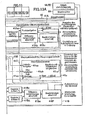
1 zeigt ein Schemadiagramm des Gesamtaufbaus eines Teilchenstrahlbestrahlungsgeräts nach einer Ausführungsform der vorliegenden Erfindung. 1 Fig. 12 is a schematic diagram showing the overall structure of a particle beam irradiation apparatus according to an embodiment of the present invention.
2 zeigt ein Ablaufdiagramm für das Steuerungsverfahren, das von den Computereinrichtungen in der in 1 gezeigten Behandlungsplanungseinheit ausgeführt wird. 2 FIG. 3 shows a flow chart for the control method used by the computer facilities in the in 1 executed treatment planning unit is executed.
3 zeigt ein Schemadiagramm mit einem Beispiel der Dosisverteilung in jeder Schicht zur Sicherstellung der Gleichmäßigkeit in einem betroffenen Bereich. 3 Fig. 12 is a schematic diagram showing an example of the dose distribution in each layer for ensuring uniformity in an affected area.
4 zeigt ein Diagramm zur Illustration eines Beispiels des betroffenen Bereichs, der mit dem in 1 gezeigten Teilchenstrahlbestrahlungsgerät bestrahlt wird. 4 FIG. 4 is a diagram illustrating an example of the affected area associated with the in 1 irradiated particle beam irradiation apparatus is irradiated.
5 zeigt ein Schemadiagramm mit einem Beispiel der Dosisverteilung in jeder Schicht zur Sicherstellung der Gleichmäßigkeit in einem betroffenen Bereich. 5 Fig. 12 is a schematic diagram showing an example of the dose distribution in each layer for ensuring uniformity in an affected area.
6 zeigt ein Ablaufdiagramm für das Steuerungsverfahren, das von den Computereinrichtungen in der in 1 gezeigten Behandlungsplanungseinheit ausgeführt wird. 6 FIG. 3 shows a flow chart for the control method used by the computer facilities in the in 1 executed treatment planning unit is executed.
7 zeigt eine Tabelle mit einem Beispiel für die Anzahl der Unterteilungen für jede Schicht zum Zeitpunkt der Bestrahlung, wobei die Anzahl der Unterteilungen in der in 1 gezeigten Behandlungsplanungseinheit geplant wird. 7 FIG. 12 is a table showing an example of the number of divisions for each layer at the time of irradiation, wherein the number of divisions in FIG 1 planned treatment planning unit is planned.
8 zeigt eine Tabelle mit einem Beispiel des Unterteilungsmodus für jede Schicht zum Zeitpunkt der Bestrahlung, wobei der Unterteilungsmodus in der in 1 gezeigten Behandlungsplanungseinheit geplant wird. 8th FIG. 12 shows a table showing an example of the division mode for each layer at the time of irradiation, wherein the division mode is shown in FIG 1 planned treatment planning unit is planned.
9 zeigt eine schematische Aufsicht zur Veranschaulichung eines Beispiels des Abtastmodus für jede Schicht zum Zeitpunkt der Bestrahlung, wobei der Abtastmodus in der in 1 gezeigten Behandlungsplanungseinheit geplant worden ist. 9 FIG. 12 is a schematic plan view illustrating an example of the scanning mode for each layer at the time of irradiation, wherein the scanning mode is shown in FIG 1 planned treatment planning unit has been planned.
10 zeigt eine schematische Aufsicht zur Veranschaulichung eines weiteren Beispiels des Abtastmodus für jede Schicht zum Zeitpunkt der Bestrahlung, wobei der Abtastmodus in der in 1 gezeigten Behandlungsplanungseinheit geplant worden ist. 10 FIG. 12 is a schematic plan view illustrating another example of the scanning mode for each layer at the time of irradiation, wherein the scanning mode is shown in FIG 1 planned treatment planning unit has been planned.
11 zeigt eine Tabelle mit dem Inhalt von Befehlssignalen zur Ausführung des Abtastmodus für jede Schicht zum Zeitpunkt der Bestrahlung, wobei die Befehlssignale in der in 1 gezeigten Behandlungsplanungseinheit geplant worden sind. 11 FIG. 12 shows a table with the contents of command signals for executing the scan mode for each layer at the time of irradiation, with the command signals in the in. FIG 1 planned treatment planning unit have been planned.
12 zeigt ein Ablaufdiagramm für das Steuerungsverfahren, das von der Abtast-Steuereinheit und der Beschleuniger- und Transportsystem-Steuereinheit in 1 ausgeführt wird. 12 FIG. 12 is a flowchart for the control method used by the scan control unit and the accelerator and transport system control unit in FIG 1 is performed.
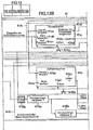
13 zeigt ein detailliertes Funktionsblockdiagramm mit dem funktionalen Aufbau der in 1 gezeigten Abtast-Steuereinheit. 13 shows a detailed functional block diagram with the functional structure of in 1 shown sampling control unit.
14 zeigt ein Ablaufdiagramm mit den Einzelheiten des Steuerungsverfahrens, das von der Abtast-Steuereinheit in 1 ausgeführt wird. 14 shows a flowchart with the details of the control method that is used by the scan control unit in 1 is performed.
15 zeigt ein Taktdiagramm zur Veranschaulichung der Betriebsabläufe in dem Aufnahmezähler und dem Vorwahlzähler in 13. 15 shows a timing diagram illustrating the operations in the recording counter and the preset counter in 13 ,
16 zeigt ein Taktdiagramm mit einem Beispiel für die Betriebsabläufe in einem Vorwahlzähler und einem Aufnahmezähler sowie des tatsächlichen Strahlbetriebs, der mit den Steuerungsverfahren realisiert wird, die von einem Vorwahlzähler-Steuerungsabschnitt und einem Aufnahmezähler-Steuerungsabschnitt in 14 ausgeführt werden. 16 FIG. 12 is a timing chart showing an example of the operations in a preset counter and a recording counter and the actual shot operation realized by the control methods executed by a preset counter control section and a recording counter control section in FIG 14 be executed.
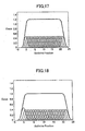
17 zeigt ein Diagramm mit einem Beispiel für die Bestrahlungsdosisverteilung, die mit einem Vergleichsbeispiel nach der vorliegenden Erfindung realisiert wird, wobei das Vergleichsbeispiel der herkömmlichen Technik entspricht. 17 Fig. 10 is a diagram showing an example of the irradiation dose distribution realized by a comparative example according to the present invention, which comparative example is the conventional technique.
18 zeigt ein Diagramm mit einem Beispiel für die Bestrahlungsdosisverteilung, die mit den Steuerungsverfahren realisiert werden, die von dem Vorwahlzähler-Steuerungsabschnitt und dem Aufnahmezähler-Steuerungsabschnitt in 14 ausgeführt werden. 18 FIG. 15 is a diagram showing an example of the irradiation dose distribution realized by the control methods executed by the preset counter control section and the recording counter control section in FIG 14 be executed.
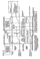
19 zeigt ein Schemadiagramm des Gesamtaufbaus eines Teilchenstrahlbestrahlungsgeräts nach einer weiteren Ausführungsform der vorliegenden Erfindung. 19 Fig. 12 is a schematic diagram showing the overall structure of a particle beam irradiation apparatus according to another embodiment of the present invention.
BESCHREIBUNG DER BEVORZUGTEN AUSFÜHRUNGSFORMENDESCRIPTION OF THE PREFERRED EMBODIMENTS
Nachstehend wird ein Teilchenstrahlbehandlungssystem mit einem Teilchenstrahlbestrahlungsgerät nach einer Ausführungsform der vorliegenden Erfindung unter Bezugnahme auf die anliegenden Zeichnungen beschrieben.Hereinafter, a particle beam treatment system with a particle beam irradiation apparatus according to an embodiment of the present invention Invention described with reference to the accompanying drawings.
Wie in 1 gezeigt, umfasst ein Protonenstrahl-Behandlungssystem, das ein Teilchenstrahlbehandlungssystem nach dieser Ausführungsform darstellt, eine Erzeugungseinheit 1 für geladene Teilchenstrahlen und ein Strahltransportsystem 4, das auf der stromabwärtigen Seite der Erzeugungseinheit 1 für geladene Teilchenstrahlen angeschlossen istAs in 1 As shown in FIG. 1, a proton beam treatment system constituting a particle beam treatment system according to this embodiment includes a generation unit 1 for charged particle beams and a beam transport system 4 located on the downstream side of the generating unit 1 is connected for charged particle beams
Die Erzeugungseinheit 1 für geladene Teilchenstrahlen umfasst eine Ionenquelle (nicht gezeigt), eine Vorstufen-Erzeugungseinheit 11 für geladene Teilchenstrahlen (Linearbeschleuniger (Linac)) und ein Synchrotron (Beschleuniger) 12. Das Synchrotron 12 weist eine Hochfrequenz-Anlegeeinheit 9 und eine Beschleunigungseinheit 10 auf. Die Hochfrequenz-Anlegeeinheit 9 ist dadurch gebildet, dass eine Hochfrequenzelektrode 93, die auf der Kreisumlaufbahn des Synchrotrons 12 angeordnet ist, und eine Hochfrequenz-Energiequelle 91 durch einen Auf/Zu-Schalter 92 verbunden sind. Die Beschleunigungseinheit (zweites Element, Energieänderungseinheit für geladene Teilchenstrahlen) 10 umfasst einen Hochfrequenz-Beschleunigungsresonator (nicht gezeigt), der auf ihrer Kreisumlaufbahn angeordnet ist, und eine Hochfrequenz-Energiequelle (nicht gezeigt) zum Anlegen von Hochfrequenzenergie an den Hochfrequenz-Beschleunigungs resonator. In der Ionenquelle erzeugte Ionen, zum Beispiel Wasserstoffionen (Protonen) oder Kohlenstoffionen, werden durch die Vorstufen-Erzeugungseinheit 11 für geladene Teilchenstrahlen (zum Beispiel die lineare Erzeugungseinheit für geladene Teilchenstrahlen) beschleunigt. Der von der Vorstufen-Erzeugungseinheit 11 für geladene Teilchenstrahlen ausgestrahlte Ionenstrahl (Protonenstrahl) wird in das Synchrotron 12 eingeführt. Im Synchrotron 12 wird dieser Ionenstrahl, der ein geladener Teilchenstrahl ist, mit Energie beaufschlagt und durch die Hochfrequenzenergie beschleunigt, die durch den Hochfrequenz-Beschleunigungsresonator aus der Hochfrequenz-Energiequelle 91 an den Ionen strahl angelegt wird. Nachdem die Energie des durch das Synchrotron 12 umlaufenden Ionenstrahls bis auf eine eingestellte Energie (zum Beispiel 100 bis 200 MeV) erhöht worden ist, erreicht eine Hochfrequenz zur Emission aus der Hochfrequenz-Energiequelle 91 die Hochfrequenzelektrode 93 durch den Auf/Zu-Schalter 92 in geschlossenem Zustand und wird an den Ionenstrahl aus der Hochfrequenzelektrode 93 angelegt. Das Anlegen dieser Hochfrequenz bewirkt, dass sich der Ionenstrahl, der innerhalb einer Stabilitätsgrenze umläuft, zur Außenseite der Stabilitätsgrenze verschiebt, wodurch der Ionenstrahl durch einen Extraktionsdeflektor 8 aus dem Synchrotron 12 extrahiert wird. Bei der Extraktion des Ionenstrahls werden die den Quadrupol-Elektromagneten 13 und den Beugungselektromagneten 14 zugeführten Ströme auf eingestellten Werten gehalten, und die Stabilitätsgrenze wird im Wesentlichen konstant gehalten. Durch Öffnen des Auf/Zu-Schalters 92, um das Anlegen der Hochfrequenzenergie an die Hochfrequenzelektrode 93 zu unterbrechen, wird die Extraktion des Ionenstrahls aus dem Synchrotron 12 unterbrochen.The generating unit 1 For charged particle beams, an ion source (not shown) comprises a precursor generation unit 11 for charged particle beams (linear accelerator (Linac)) and a synchrotron (accelerator) 12 , The synchrotron 12 has a high frequency application unit 9 and an acceleration unit 10 on. The high-frequency application unit 9 is formed by a high-frequency electrode 93 placed on the circular orbit of the synchrotron 12 is arranged, and a high frequency power source 91 through an on / off switch 92 are connected. The acceleration unit (second element, charged particle energy change unit) 10 comprises a high-frequency acceleration resonator (not shown) disposed in its circular orbit, and a high-frequency power source (not shown) for applying high-frequency power to the high-frequency acceleration resonator. Ions generated in the ion source, for example, hydrogen ions (protons) or carbon ions, are passed through the precursor generation unit 11 for charged particle beams (for example, the charged particle beam linear generating unit). That of the precursor generation unit 11 For charged particle beams emitted ion beam (proton beam) is in the synchrotron 12 introduced. In the synchrotron 12 For example, this ion beam, which is a charged particle beam, is energized and accelerated by the high frequency energy generated by the high frequency acceleration resonator from the high frequency power source 91 is applied to the ion beam. After the energy of the synchrotron 12 circulating ion beam has been increased to a set energy (for example 100 to 200 MeV) reaches a high frequency for emission from the high frequency power source 91 the high-frequency electrode 93 through the on / off switch 92 in the closed state and is applied to the ion beam from the radio frequency electrode 93 created. The application of this high frequency causes the ion beam, which orbits within a stability limit, to shift to the outside of the stability limit, causing the ion beam to pass through an extraction deflector 8th from the synchrotron 12 is extracted. Upon extraction of the ion beam, they become the quadrupole electromagnets 13 and the diffraction electromagnet 14 supplied currents are kept at set values, and the stability limit is kept substantially constant. By opening the on / off switch 92 to apply the radio frequency energy to the radio frequency electrode 93 to interrupt, the extraction of the ion beam from the synchrotron 12 interrupted.
Der aus dem Synchrotron 12 extrahierte Ionenstrahl wird zur stromabwärtigen Seite des Strahltransportsystems 4 transportiert. Das Strahltransportsystem 4 umfasst Quadrupol-Elektromagnete 18 und einen Ablenkelektromagnet 17 sowie Quadrupol-Elektromagnete 21 und 22 und Ablenkelektromagnete 23 und 24, die nacheinander auf einem Strahlweg 62 angeordnet sind, der mit dem Strahlausgabegerät 15 in einem Behandlungsraum von der stromaufwärtigen Seite in Strahllaufrichtung verbunden ist. Hierbei bilden die vorstehend genannten Elektromagnete jeweils ein erstes Element. Der in das Strahltransportsystem 4 eingeführte Ionenstrahl wird durch den Strahlweg 62 zum Strahlausgabegerät 15 transportiert.The one from the synchrotron 12 extracted ion beam becomes the downstream side of the beam transport system 4 transported. The jet transport system 4 includes quadrupole electromagnets 18 and a deflection electromagnet 17 as well as quadrupole electromagnets 21 and 22 and deflection electromagnets 23 and 24 , one after the other on a beam path 62 are arranged with the jet dispenser 15 is connected in a treatment space from the upstream side in the jet running direction. In this case, the above-mentioned electromagnets each form a first element. The into the jet transport system 4 introduced ion beam is through the beam path 62 to the jet dispenser 15 transported.
Im Behandlungsraum ist das Strahlausgabegerät 15 an einer darin vorgesehenen rotierenden Gantry (nicht gezeigt) angebracht. Eine Strahltransporteinheit mit umgekehrter U-Form, die einen Teil des Strahlwegs 62 im Strahltransport system 4 einschließt, und das Strahlausgabegerät 15 sind in einer rotierenden Trommel (nicht gezeigt) mit im Wesentlichen zylindrischer Form in der rotierenden Gantry (nicht gezeigt) angeordnet. Die rotierende Trommel ist so beschaffen, dass sie mit einem Motor (nicht gezeigt) gedreht werden kann. Ein Bestrahlungsfeld (nicht gezeigt) ist in der rotierenden Trommel gebildet.In the treatment room is the jet dispenser 15 attached to a rotating gantry (not shown) provided therein. A jet transport unit of inverted U-shape forming part of the beam path 62 in the beam transport system 4 includes, and the jet dispenser 15 are arranged in a rotating drum (not shown) of substantially cylindrical shape in the rotating gantry (not shown). The rotating drum is adapted to be rotated by a motor (not shown). An irradiation field (not shown) is formed in the rotary drum.
Das Strahlausgabegerät 15 weist ein Gehäuse (nicht gezeigt) auf, das an der rotierenden Trommel angebracht und mit der vorstehend genannten Strahltransporteinheit mit umgekehrter U-Form verbunden ist. Abtastelektromagnete 5A und 5B zum Abtasten eines Strahls, ein Dosismonitor 6A, ein Positionsmonitor 6B und dergleichen sind in dem Gehäuse angeordnet. Die Abtastelektromagnete 5A und 5B werden verwendet, um einen Strahl zum Beispiel in zueinander senkrechten, einander schneidenden Richtungen (einer X-Richtung und einer Y-Richtung) auf einer zur Strahlachse senkrechten Ebene abzulenken und um eine Bestrahlungsposition in X- und Y-Richtung zu bewegen.The jet dispenser 15 has a housing (not shown) attached to the rotary drum and connected to the aforementioned U-shaped beam transport unit. scanning electromagnets 5A and 5B for scanning a beam, a dose monitor 6A , a position monitor 6B and the like are arranged in the housing. The scanning electromagnets 5A and 5B are used to deflect a beam in, for example, mutually perpendicular intersecting directions (an X direction and a Y direction) on a plane perpendicular to the beam axis and to move an irradiation position in the X and Y directions.
Bevor ein Ionenstrahl aus dem Strahlausgabegerät 15 ausgestrahlt wird, wird eine Behandlungsliege 29 durch eine Liegentransporteinheit (nicht gezeigt) transportiert und in das vorstehend genannte Bestrahlungsfeld eingebracht; danach wird die Positionierung der Liege 29 für die Bestrahlung in Bezug auf das Strahlausgabegerät 15 durchgeführt. Die rotierende Trommel wird durch Steuerung der Drehung des Motors durch eine Gantry-Steuereinheit (nicht gezeigt) so gedreht, dass die Strahlachse des Strahlausgabegeräts 15 zu dem betroffenen Körperteil eines Patienten 30 gedreht wird. Der aus der umgekehrt U-förmigen Strahltransporteinheit durch den Strahlweg 62 in das Strahlausgabegerät 15 eingeführte Ionenstrahl wird durch die Abtastelektromagnete (geladene Teilchenstrahl-Abtasteinheit) 5A und 5B veranlasst, nacheinander die Bestrahlungspositionen abzutasten, und auf den betroffenen Körperteil (zum Beispiel den von einem Krebs oder Tumor betroffenen Bereich) des Patienten 30 gelenkt. Dieser Ionenstrahl setzt seine Energie in dem betroffenen Körperteil frei und bildet dort einen Hochdosisbereich. Die Abtastelektromagnete 5A und 5B im Strahlausgabegerät 15 werden von einer Abtast-Steuereinheit 41 gesteuert, die zum Beispiel in der Gantry-Kammer in einer Behandlungseinheit angeordnet ist.Before an ion beam from the jet dispenser 15 is broadcast, becomes a treatment couch 29 transported by a couch transport unit (not shown) and introduced into the above-mentioned irradiation field; after that, the positioning of the lounger 29 for irradiation with respect to the jet dispenser 15 carried out. The rotating drum is controlled by the Rotation of the motor through a gantry control unit (not shown) rotated so that the beam axis of the jet dispenser 15 to the affected body part of a patient 30 is turned. The from the inverted U-shaped beam transport unit through the beam path 62 into the jet dispenser 15 introduced ion beam is passed through the scanning electromagnets (charged particle beam scanning unit) 5A and 5B causing the patient to sequentially scan the irradiation positions and to the affected body part (for example, the area affected by a cancer or tumor) 30 directed. This ion beam releases its energy in the affected body part and forms a high-dose area there. The scanning electromagnets 5A and 5B in the jet dispenser 15 be from a scanning control unit 41 controlled, which is arranged for example in the gantry chamber in a treatment unit.
Ein Steuerungssystem in dem Protonenstrahl-Behandlungssystem nach dieser Ausführungsform wird anhand von 1 beschrieben. Dieses Steuerungssystem 90 weist eine zentrale Steuerungseinheit 100, eine Speichereinheit 110 zur Speicherung der Behandlungsplanungsdatenbank, eine Abtast-Steuereinheit 41 und eine Beschleuniger- und Transportsystem-Steuereinheit 40 (nachstehend als „Beschleuniger-Steuereinheit” bezeichnet) auf. Weiter weist das Protonenstrahl-Behandlungssystem nach dieser Ausführungsform eine Behandlungsplanungseinheit 140 auf.A control system in the proton beam treatment system according to this embodiment will be described with reference to FIG 1 described. This control system 90 has a central control unit 100 , a storage unit 110 for storing the treatment planning database, a scan control unit 41 and an accelerator and transport system controller 40 (hereinafter referred to as "accelerator control unit"). Further, the proton beam treatment system according to this embodiment has a treatment planning unit 140 on.
Obwohl die vorstehend genannten Behandlungsplanungsdaten (Patientendaten), die für jeden einzelnen Patienten in der Speichereinheit 110 gespeichert sind, nicht im Einzelnen gezeigt sind, umfassen die Behandlungsplanungsdaten zum Beispiel Daten wie Patientennummern, Bestrahlungsdosen (durch eine Behandlung und/oder pro Teil), Bestrahlungsenergie, Bestrahlungsrichtungen, Bestrahlungspositionen usw.Although the above treatment planning data (patient data), for each individual patient in the storage unit 110 are not shown in detail, the treatment planning data include, for example, data such as patient numbers, radiation doses (by treatment and / or by part), irradiation energy, irradiation directions, irradiation positions, etc.
Die zentrale Steuerungseinheit 100 weist eine CPU und einen Speicher 103 auf. Die CPU 101 liest die vorstehend beschriebenen Behandlungsplanungsdaten für die zu behandelnden Patienten anhand der eingegebenen Patientenkenndaten aus der Speichereinheit 110 aus. Das Steuerungsmuster im Hinblick auf die Anregungsenergiezufuhr zu jedem der vorstehend beschriebenen Elektromagnete wird durch den Wert der Bestrahlungsenergie aus den Behandlungsplanungsdaten individuell für jeden Patienten bestimmt.The central control unit 100 has a CPU and a memory 103 on. The CPU 101 reads the above-described treatment planning data for the patients to be treated from the storage unit on the basis of the entered patient characteristics 110 out. The control pattern with respect to the excitation power supply to each of the electromagnets described above is determined by the value of the irradiation energy from the treatment planning data individually for each patient.
Der Speicher 103 speichert im Voraus eine Stromversorgungs-Steuerungstabelle. Im Einzelnen sind zum Beispiel entsprechend den verschiedenen Werten der Bestrahlungsenergie (70, 80, 90, ... [MeV]) Werte für die Anregungsenergiezufuhr oder deren Muster im Hinblick auf einen Quadrupol-Elektromagnet 13 und einen Ablenkelektromagnet 14 in der Erzeugungseinheit 1 für geladene Teilchenstrahlen mit dem Synchrotron 12 sowie die Quadrupol-Elektromagnete 18, den Ablenkelektromagnet 17, die Quadrupol-Elektromagnete 21 und 22 und die Ablenkelektromagnete 23 und 24 im Strahltransportsystem 4 voreingestellt.The memory 103 stores in advance a power supply control table. Specifically, for example, according to the different values of the irradiation energy (70, 80, 90, ... [MeV]), there are values for the excitation energy supply or its pattern with respect to a quadrupole electromagnet 13 and a deflection electromagnet 14 in the production unit 1 for charged particle beams with the synchrotron 12 as well as the quadrupole electromagnets 18 , the deflection electromagnet 17 , the quadrupole electromagnets 21 and 22 and the deflection electromagnets 23 and 24 in the jet transport system 4 preset.
Außerdem erzeugt die CPU 101 als Steuerungsinformations-Erzeugungseinheit anhand der vorstehend beschriebenen Behandlungsplanungsdaten und der Stromversorgungs-Steuerungstabelle Steuerbefehldaten (Steuerbefehlinformationen) zur Steuerung der Elektromagnete in der Erzeugungseinheit 1 für geladene Teilchenstrahlen und den Strahlwegen für einen zu behandelnden Patienten. Danach gibt die CPU 101 die auf diese Weise erzeugten Steuerbefehldaten an die Abtast-Steuereinheit 41 und die Beschleuniger-Steuereinheit 40 aus.In addition, the CPU generates 101 as a control information generation unit based on the treatment planning data described above and the power supply control table, control instruction data (control instruction information) for controlling the electromagnets in the generation unit 1 for charged particle beams and the beam paths for a patient to be treated. After that, the CPU gives 101 the control instruction data generated in this way to the scan control unit 41 and the accelerator control unit 40 out.
Eine der Besonderheiten dieser Ausführungsform besteht darin, dass die zentrale Steuerungseinheit 100, die Abtast-Steuereinheit 41 und die Beschleuniger-Steuereinheit 40 basierend auf den von der Behandlungsplanungseinheit 140 erzeugten Behandlungsplanungsdaten die Steuerungsoperationen in enger Abstimmung miteinander wie folgt durchführen: (1) Sie unterbrechen die Ausstrahlung eines Ionenstrahls aus dem Strahlausgabegerät 15 und, in einem Zustand, in dem die Ausstrahlung des Ionenstrahls unterbrochen ist, steuern sie die Abtastelektromagnete 5A und 5B so, dass die Bestrahlungsposition (Punkt) des Ionenstrahls geändert wird und nach der Änderung die Ausstrahlung des Ionenstrahls aus dem Strahlausgabegerät 15 begonnen wird (das so genannte „Abtasten”), und (2) steuern sie, um Schwankungen in der Bestrahlungsdosis an einem Punkt zu verringern, das Synchrotron 12 und das Strahlausgabegerät 15 so, dass die Ausstrahlung eines Ionenstrahls im Hinblick auf wenigstens eine identische Bestrahlungsposition (Punkt), an der die Dosis ansonsten eine Unterteilungs-Referenzbestrahlungsdosis (nachstehend erläutert) übersteigen würde, in mehrere Bestrahlungsvorgänge unterteilt wird.One of the peculiarities of this embodiment is that the central control unit 100 , the scanning control unit 41 and the accelerator control unit 40 based on the treatment planning unit 140 treatment planning data generated, the control operations in close coordination with each other as follows: (1) they interrupt the emission of an ion beam from the jet dispenser 15 and, in a state where the emission of the ion beam is interrupted, they control the scanning electromagnets 5A and 5B such that the irradiation position (point) of the ion beam is changed and, after the change, the radiation of the ion beam from the beam output device 15 (so-called "sampling"), and (2) control the synchrotron to reduce fluctuations in the radiation dose at one point 12 and the jet dispenser 15 such that the emission of an ion beam is subdivided into a plurality of irradiation operations with respect to at least one identical irradiation position (point) at which the dose would otherwise exceed a subdivision reference irradiation dose (discussed below).
Nachstehend wird dies anhand von 2 bis 18 ausführlich beschrieben.The following is based on 2 to 18 described in detail.
Zuerst wird die Erstellung eines Behandlungsplans durch die Behandlungsplanungseinheit 140 erläutert. Die Behandlungsplanungseinheit 140 besteht zum Beispiel aus einem Personalcomputer. Auch wenn in der Abbildung nicht gezeigt, umfasst die Behandlungsplanungseinheit 140 eine Eingabeeinheit (zum Beispiel eine Tastatur), die von einem Bediener betätigt werden kann und mit der er Eingaben vornehmen kann, eine Computereinheit (zum Beispiel eine CPU), die eine vorbestimmte arithmetische Verarbeitung auf der Grundlage einer Eingabe über die vorstehend erwähnte Eingabeeinrichtung und Bedieneinrichtung durchführt, eine Ein-/Ausgabeschnittstelle, die die Eingabe bzw. Ausgabe von Informationen durchführt, zum Beispiel die Eingabe externer Bilddaten und die Ausgabe von mit dieser Computereinheit erzeugten Behandlungsplanungsdaten, und eine Anzeigeeinheit.First, the preparation of a treatment plan by the treatment planning unit 140 explained. The treatment planning unit 140 consists of a personal computer, for example. Although not shown in the figure, the treatment planning unit includes 140 an input unit (for example a keyboard) that can be operated by an operator and with which he can make inputs, a computer unit (for example a CPU) that has a predetermined value performs arithmetic processing based on input via the above-mentioned input device and operating device, an input / output interface that performs the input / output of information, for example, the input of external image data and the output of treatment planning data generated with this computer unit; display unit.
2 zeigt ein Ablaufdiagramm der Arithmetikverarbeitungsschritte, die von den vorstehend genannten Computereinrichtungen in der Behandlungsplanungseinheit 140 ausgeführt werden. In 2 ist, wenn ein Bediener (im Allgemeinen ein Arzt oder ein Angehöriger des medizinischen Personals) Identifikationsinformationen (zum Beispiel einen Namen oder eine ID-Nummer) für einen zu behandelnden Patienten über die Eingabeeinheit eingibt, die Bedingung in Schritt 101 erfüllt, und die Verarbeitung wird mit Schritt 102 fortgesetzt, in dem eine Patientenbilddatei (eine zuvor mit zusätzlichen Aufnahmeeinrichtungen wie einem CT-Scanner aufgenommene und in der Datenbank in der Speichereinheit 110 gespeicherte Datei) des betreffenden Patienten gelesen wird. Hier handelt es sich bei der Patientenbilddatei um Tomographieaufnahmen. 2 FIG. 12 is a flow chart of the arithmetic processing steps performed by the aforementioned computing devices in the treatment planning unit. FIG 140 be executed. In 2 is when an operator (generally, a doctor or a member of the medical staff) inputs identification information (for example, a name or an ID number) for a patient to be treated through the input unit, the condition in step 101 fulfilled, and the processing comes with step 102 in which a patient image file (a previously recorded with additional recording devices such as a CT scanner and in the database in the memory unit 110 stored file) of the patient in question is read. Here, the patient image file is a tomographic image.
Danach wird in Schritt 103 die gelesene Patientenbilddatei auf einer Anzeigeeinheit als Anzeigesignale ausgegeben und eine entsprechende Darstellung erfolgt. Wenn der Bediener die Spezifikation durchführt, indem er über die Eingabeeinheit einen mit einem Ionenstrahl zu bestrahlenden Zielbereich eingibt, während er die angezeigte Patientenbilddatei betrachtet, ist die Bedingung in Schritt 104 erfüllt, und die Verarbeitung wird mit Schritt 105 fortgesetzt, in dem eine dreidimensionale Erkennungsverarbeitung im Hinblick auf den eingegebenen Bereich durchgeführt wird. Wenn der Bediener in dieser Situation über die Eingabeeinheit eine Solldosis eingibt, die auf einen entsprechenden Zielbereich angewendet werden soll, ist die Bedingung in Schritt 106 erfüllt. Wenn der Bediener weiter eine Bestrahlungsrichtung für den Ionenstrahl eingibt, ist die Bedingung in Schritt 107 erfüllt, und die Verarbeitung wird mit Schritt 108 fortgesetzt. Wenn der Bediener außerdem über die Eingabeeinheit eine Unterteilungs-Referenzbestrahlungsdosis eingibt, das heißt eine solche Referenzbestrahlungsdosis, dass eine unterteilte Bestrahlung durchgeführt wird, wenn eine Bestrahlungsdosis pro Flächeneinheit diese Referenzbestrahlungsdosis übersteigt, ist die Bedingung in Schritt 108 erfüllt, und die Verarbeitung wird mit Schritt 110 fortgesetzt.After that, in step 103 the read patient image file is output on a display unit as display signals and a corresponding representation is made. When the operator performs the specification by inputting, via the input unit, a target area to be irradiated with an ion beam while viewing the displayed patient image file, the condition is in step 104 fulfilled, and the processing comes with step 105 continued, in which a three-dimensional recognition processing is performed with respect to the inputted area. In this situation, when the operator inputs a target dose to be applied to a corresponding target area via the input unit, the condition is in step 106 Fulfills. If the operator continues to input an irradiation direction for the ion beam, the condition in step 107 fulfilled, and the processing comes with step 108 continued. In addition, when the operator inputs a subdivision reference irradiation dose via the input unit, that is, a reference irradiation dose such that a divided irradiation is performed when an irradiation dose per unit area exceeds this reference irradiation dose, the condition in step 108 fulfilled, and the processing comes with step 110 continued.
Nachstehend wird der Zusammenhang zwischen der Tiefe eines Ziels und der Energie eines Ionenstrahls beschrieben. Das Ziel oder Target ist ein Bereich, einschließlich eines betroffenen Körperteils, der mit einem Ionenstrahl bestrahlt werden soll, und ist etwas größer als der betroffene Körperteil. 3 zeigt den Zusammenhang zwischen der Tiefe des Targets im Körper und der Bestrahlungsdosis des Ionenstrahls. Der Peak der Dosis, wie in 3 gezeigt, wird als „Bragg-Peak” bezeichnet. Das Anwenden eines Ionenstrahls auf das Target erfolgt an der Position des Bragg-Peaks. Die Position des Bragg-Peaks variiert je nach der Energie des Ionenstrahls. Daher ist es durch Unterteilen des Targets in mehrere Schichten (Schnitte) in Tiefenrichtung (Laufrichtung des Ionenstrahls im Körper) und Ändern der Energie des Ionenstrahls auf die Energie entsprechend der Tiefe (der Schicht) möglich, den Ionenstrahl über das gesamte Target (Zielbereich) mit einer in Tiefenrichtung möglichst gleichmäßigen Dicke auszustrahlen. Unter diesem Gesichtspunkt wird in Schritt 110 die Anzahl der Schichten in dem zu unterteilenden Zielbereich in Tiefenrichtung bestimmt. Ein mögliches Verfahren zur Bestimmung der Anzahl der Schichten besteht darin, die Dicke einer Schicht festzulegen und die Anzahl der Schichten automatisch entsprechend dieser Dicke und einer Dicke des Zielbereichs in Tiefenrichtung zu bestimmen. Die Dicke der Schicht kann ein fester Wert unabhängig von der Größe des Zielbereichs sein oder sie kann alternativ entsprechend der maximalen Tiefe des Zielbereichs automatisch bestimmt werden. Nach einer weiteren Alternative kann die Dicke der Schicht automatisch entsprechend der Ausbreitung der Energie des Ionenstrahls bestimmt werden, oder die Anzahl der Schichten selbst kann einfach vom Bediener über die Eingabeeinheit eingegeben werden, anstatt die Dicke der Schicht zu bestimmen.The relationship between the depth of a target and the energy of an ion beam will be described below. The target is a region including an affected body part to be irradiated with an ion beam and is slightly larger than the affected body part. 3 shows the relationship between the depth of the target in the body and the irradiation dose of the ion beam. The peak of the dose, as in 3 shown is called "Bragg peak". Applying an ion beam to the target occurs at the position of the Bragg peak. The position of the Bragg peak varies depending on the energy of the ion beam. Therefore, by dividing the target into multiple layers (cuts) in the depth direction (running direction of the ion beam in the body) and changing the energy of the ion beam to the energy corresponding to the depth (of the layer), it is possible to transmit the ion beam over the entire target (target area) to emit a thickness that is as uniform as possible in the depth direction. From this point of view, in step 110 determines the number of layers in the target area to be divided in the depth direction. One possible method for determining the number of layers is to determine the thickness of a layer and to automatically determine the number of layers according to this thickness and a thickness of the target area in the depth direction. The thickness of the layer may be a fixed value regardless of the size of the target area or, alternatively, it may be determined automatically according to the maximum depth of the target area. As a further alternative, the thickness of the layer may be determined automatically according to the propagation of the energy of the ion beam, or the number of layers themselves may simply be entered by the operator via the input unit, rather than determining the thickness of the layer.
4 zeigt ein Diagramm mit einem Beispiel für nach dem vorstehend beschriebenen Verfahren bestimmte Schichten. In diesem Beispiel beträgt die Anzahl der Schichten vier, und zwar Schicht 1, 2, 3 und 4 in dieser Reihenfolge von der untersten Schicht. Die Schichten 1 und 2 weisen jeweils eine Ausdehnung von 10 cm in X-Richtung und von 10 cm in Y-Richtung auf. Die Schichten 3 und 4 weisen jeweils eine Ausdehnung von 20 cm in X-Richtung und von 10 cm in Y-Richtung auf. 3 zeigt ein Beispiel für die Dosisverteilung in Tiefenrichtung entlang der Linie A-A' in 4. Andererseits zeigt 5 ein Beispiel für die Dosisverteilung in Tiefenrichtung entlang der Linie B-B' in 4. 4 shows a diagram with an example of layers determined by the method described above. In this example, the number of layers is four, layers 1, 2, 3, and 4 in this order from the lowest layer. The layers 1 and 2 each have an extension of 10 cm in the X direction and 10 cm in the Y direction. The layers 3 and 4 each have an extension of 20 cm in the X direction and 10 cm in the Y direction. 3 shows an example of the dose distribution in the depth direction along the line AA 'in 4 , On the other hand shows 5 an example of the dose distribution in the depth direction along the line BB 'in 4 ,
Nachdem die Anzahl der Schichten auf diese Weise bestimmt worden ist, wird die Verarbeitung mit Schritt 111 fortgesetzt, in dem die Anzahl (und die Positionen) der Punkte bestimmt wird, die die einzelnen Schichten (Target-Querschnitt) jeweils in der Richtung senkrecht zur Tiefenrichtung unterteilen. Bei dieser Bestimmung wird ähnlich wie bei den vorstehend beschriebenen Schichten ein Punktdurchmesser festgelegt, und die Anzahl der Punkte wird automatisch entsprechend der Größe des Punktes und der Größe der zugehörigen Schicht bestimmt. Der Punktdurchmesser kann ein fester Wert sein oder er kann alternativ automatisch entsprechend dem Target-Querschnitt bestimmt werden. Nach einer weiteren Alternative kann der Punktdurchmesser automatisch entsprechend der Größe des Ionenstrahls (das heißt dem Strahldurchmesser) bestimmt werden, oder die Punktpositionen selbst oder der Abstand zwischen den Punktpositionen können vom Bediener einfach über die Eingabeeinheit eingegeben werden, anstatt die Punktgröße zu bestimmen. Nach Abschluss von Schritt 111 wird die Verarbeitung mit Schritt 120 fortgesetzt, in dem die Bestrahlungsdosis an jedem Punkt in allen Schichten bestimmt wird.After the number of layers has been determined in this way, the processing in step 111 is continued, in which the number (and the positions) of the points is determined, which divide the individual layers (target cross section) respectively in the direction perpendicular to the depth direction. In this determination, similar to the above-described layers, a dot diameter is set, and the number of dots is automatically determined according to the size of the dot and the size of the associated layer. The dot diameter may be a fixed value or he can alternatively be determined automatically according to the target cross-section. According to another alternative, the dot diameter may be automatically determined according to the size of the ion beam (ie, the beam diameter), or the dot positions themselves or the distance between the dot positions may be simply input by the operator via the input unit instead of determining the dot size. After completing step 111 the processing starts with step 120 continued, in which the irradiation dose is determined at each point in all layers.
6 zeigt ein Ablaufdiagramm für das detaillierte Verfahren im vorstehend erwähnten Schritt 120. Wie vorstehend beschrieben, erfolgt das Anwenden eines Ionenstrahls auf das Target grundsätzlich an der Position des Bragg-Peaks, und es ist wünschenswert, dass der Ionenstrahl über das gesamte Target (Zielbereich) mit einer in Tiefenrichtung möglichst gleichmäßigen Dicke ausgestrahlt wird. Bei der Bestimmung der Bestrahlungsdosis an jedem Punkt muss daher letztlich eine gleichmäßige Bestrahlung über den gesamten Zielbereich sichergestellt werden. In Anbetracht der vorstehenden Ausführungen werden in den Schritten 121 bis 123 zuerst die Ausgangsbedingungen in Schritt 121 bestimmt. Im Einzelnen werden durch Kumulierung von früheren Berechnungsbeispielen, die Anwendung einfacher Modelle oder dergleichen die Bestrahlungsdosen im Hinblick auf alle Punkte Schicht für Schicht, von denen angenommen wird, dass sie den Solldosen entsprechen, die Bestrahlungsrichtung für den Ionenstrahl und die Anzahl der Schichten, die in den Schritten 106 bis 111 eingegeben oder bestimmt wurden, als temporäre Werte bestimmt. 6 shows a flowchart for the detailed method in the aforementioned step 120 , As described above, applying an ion beam to the target is basically performed at the position of the Bragg peak, and it is desirable that the ion beam is irradiated over the entire target (target area) with a thickness as uniform as possible in the depth direction. Therefore, when determining the dose of radiation at each point, it is ultimately necessary to ensure uniform irradiation over the entire target area. In view of the above, in the steps 121 to 123 first the initial conditions in step 121 certainly. Specifically, by cumulating previous calculation examples, the application of simple models or the like, the irradiation doses with respect to all the points, layer by layer, which are assumed to correspond to the target doses, the irradiation direction for the ion beam and the number of layers, which are shown in FIG the steps 106 to 111 entered or determined as temporary values.
Danach wird die Verarbeitung mit Schritt 122 fortgesetzt, in dem nach einem bekannten Verfahren eine Simulationsrechnung durchgeführt wird, wie die tatsächliche Dosisverteilung im gesamten Zielbereich aussieht, wenn eine Bestrahlung mit den Werten für die Bestrahlungsdosen im Hinblick auf alle Punkte durchgeführt wird, wobei die Dosen in Schritt 121 bestimmt worden sind. In Schritt 123 wird dann bestimmt, ob die berechnete Dosisverteilung im Wesentlichen über den gesamten Bereich des Targets gleichmäßig ist, das heißt ob die Schwankungen innerhalb eines gegebenen Grenze liegen. Wenn nicht, wird die Verarbeitung mit Schritt 124 fortgesetzt, in dem eine vorbestimmte Korrektur vorgenommen wird. Diese Korrektur kann so sein, dass die Bestrahlungsdosen an Punkten, die etwas höher/niedriger als ein Durchschnittsdosiswert sind, automatisch mit einer Korrekturbreite verringert/erhöht werden, und dass die Korrekturbreite durch eine manuelle Operation eingestellt werden kann. Nach einer solchen Korrektur kehrt die Verarbeitung zu Schritt 121 zurück, und dasselbe Verfahren wird wiederholt. Daher werden die Korrektur in Schritt 124 und die Dosisverteilungsberechnung in Schritt 122 durchgeführt, bis die Bestrahlungsdosisverteilung bis zu einem gewissen Maß gleichmäßig ist. Daher werden letztlich die Bestrahlungsdosen im Hinblick auf alle Punkte, die eine im Wesentlichen gleichmäßige Dosisverteilung im gesamten Zielbereich ermöglichen, bestimmt. Danach wird die Verarbeitung mit Schritt 130 fortgesetzt.Thereafter, the processing with step 122 in which, according to a known method, a simulation calculation is performed, as the actual dose distribution in the entire target area looks like, when irradiation with the values for the irradiation doses with respect to all points is carried out, the doses in step 121 have been determined. In step 123 it is then determined whether the calculated dose distribution is substantially uniform over substantially the entire area of the target, that is, whether the fluctuations are within a given limit. If not, the processing goes to step 124 continued, in which a predetermined correction is made. This correction may be such that the irradiation doses at points that are slightly higher / lower than an average dose value are automatically decreased / increased with a correction width, and that the correction width can be adjusted by a manual operation. After such a correction, the processing returns to step 121 back, and the same procedure is repeated. Therefore, the correction in step 124 and the dose distribution calculation in step 122 carried out until the irradiation dose distribution is uniform to some extent. Therefore, in the end, the radiation doses are determined with respect to all points that allow a substantially uniform dose distribution throughout the target area. Thereafter, the processing with step 130 continued.
In dieser Phase werden, obwohl die Bestrahlungsdosen jeweils für alle Punkte bestimmt worden sind, alle diese Punkte jeweils so eingestellt, dass sie jeweils auf einmal mit einer zugehörigen zugewiesenen Bestrahlungsdosis bestrahlt werden. In Schritt 130 wird, wenn unter den im Hinblick auf alle Punkte bestimmten Bestrahlungsdosen solche vorliegen, die die zuvor in Schritt 108 eingegebene Unterteilungs-Referenzbestrahlungsdosis überschreiten, die Ionenstrahlbestrahlung für jeden dieser Punkte nicht auf ein mal durchgeführt, sondern in Form von in mehrere (wenigstens zwei) Vorgänge unterteilten Bestrahlungen. Hierbei wird angenommen, dass die Anzahl N der Bestrahlungen die kleinste natürliche Zahl n ist, die die Beziehung n ≥ R/Rs erfüllt, wobei R und Rs die Bestrahlungsdosis bzw. die Unterteilungs-Referenzbestrahlungsdosis an einem zugehörigen Punkt bezeichnen. Mit anderen Worten, es wird angenommen, dass die Anzahl N der Bestrahlungen ein Wert ist, der durch Aufrunden der Dezimalstellen von R dividiert durch Rs erhalten wird. Wenn N = 1 ist, gilt daher R ≤ Rs, und somit werden mehrere unterteilte Bestrahlungsvorgänge nicht durchgeführt (das heißt, die Bestrahlung erfolgt in einem Vorgang). Wenn N = 2 ist, gilt R > Rs, und daher wird geplant, dass in mehrere Vorgänge unterteilte Bestrahlungen durchgeführt werden.In this phase, although the irradiation doses have been determined for each of the points, all of these points are respectively set to be irradiated at one time with an associated irradiation dose assigned thereto. In step 130 if there are among the irradiation doses determined in respect of all points, those 108 For example, if the inputted subdivision reference irradiation dose exceeds 1, the ion beam irradiation is not performed once for each of these points but in the form of irradiations subdivided into a plurality of (at least two) processes. Here, it is assumed that the number N of irradiations is the smallest natural number n satisfying the relationship n ≥ R / Rs, where R and Rs denote the irradiation dose and the subdivision reference irradiation dose at an associated point, respectively. In other words, it is assumed that the number N of the irradiations is a value obtained by rounding up the decimal places of R divided by Rs. Therefore, when N = 1, R ≦ Rs, and thus plural divided irradiation operations are not performed (that is, the irradiation is done in one process). When N = 2, R> Rs, and therefore it is planned that irradiations divided into a plurality of operations are performed.
7 zeigt ein Beispiel (Schichten 1 bis 4) für unterteilte Bestrahlungen, wie sie vorstehend anhand von 4 und 5 beschrieben sind. In diesem Beispiel wird die Unterteilungs-Referenzbestrahlungsdosis mit 10 angenommen (ein relativer Wert ohne Einheit; dies gilt auch im Folgenden). Wie in 7 gezeigt, betrug für Schicht 1 vor der Unterteilungsverarbeitung (das heißt, wenn die Bestrahlung in einem Vorgang erfolgt) die Bestrahlungsdosis an jedem Punkt 70. In dieser Situation wird geplant, dass in sieben Vorgänge unterteilte Bestrahlungen durchgeführt werden, wobei die Bestrahlungsdosis für jede unterteilte Bestrahlung 10 beträgt. In gleicher Weise betrugen für die Schichten 2, 3 und 4 die Bestrahlungsdosen an jedem Punkt vor der Unterteilungsverarbeitung 25, 17,9 bzw. 12,6. Daher wird für die Schichten 2, 3 und 4 geplant, dass in drei, zwei bzw. zwei Vorgänge unterteilte Bestrahlungen durchgeführt werden, wobei die Bestrahlungsdosis für jede einzelne unterteilte Bestrahlung 8, 3, 9 bzw. 6,3 beträgt. 7 shows an example (layers 1 to 4) for subdivided radiation, as described above with reference to 4 and 5 are described. In this example, the subdivision reference irradiation dose is called 10 assumed (a relative value without unity, also in the following). As in 7 For layer 1, prior to subdivision processing (that is, when the irradiation is done in one process), the irradiation dose at each point was 70. In this situation, it is planned to perform subdivided irradiations in seven procedures, with the irradiation dose for each subdivided irradiation 10 is. Likewise, for layers 2, 3 and 4, the radiation doses at each point prior to subdivision processing were 25, 17.9 and 12.6, respectively. Therefore, for the layers 2, 3, and 4, it is planned to perform divided irradiations in three, two, and two operations, respectively, wherein the irradiation dose for each individual divided irradiation is 8, 3, 9, and 6.3, respectively.
Diese Vorgänge werden anhand von 8 ausführlich beschrieben. Wie vorstehend beschrieben, werden für Schicht 1 (der Bereich entsprechend der rechten Hälfte von Schicht 1 in 8; die Rechts-Links-Richtung in 8 entspricht hierbei der in 4) in sieben Vorgänge unterteilte Bestrahlungen durchgeführt, und es wird geplant, dass eine Bestrahlung mit einer Bestrahlungsdosis von 10 bei jedem der ersten bis sieben Bestrahlungsvorgänge wiederholt wird. Für Schicht 2 (der Bereich entsprechend der rechten Hälfte von Schicht 2 in 8) wird geplant, dass eine Bestrahlung mit einer Bestrahlungsdosis von 8,3 dreimal wiederholt. Für Schicht 3, bezogen auf den Bereich in der rechten Hälfte in 8, wird geplant, dass eine Bestrahlung mit einer Bestrahlungsdosis von 9,0 zweimal wiederholt wird, während bezogen auf den Bereich in der linken Hälfte in 8 geplant wird, dass eine Bestrahlung mit einer Bestrahlungsdosis von 10 siebenmal wiederholt wird. Für Schicht 4, bezogen auf den Bereich in der rechten Hälfte in 8, wird geplant, dass eine Bestrahlung mit einer Bestrahlungsdosis von 6,3 zweimal wiederholt wird, während bezogen auf den Bereich in der linken Hälfte in 8 geplant wird, dass eine Bestrahlung mit einer Bestrahlungsdosis von 8,3 dreimal wiederholt wird. These operations are based on 8th described in detail. As described above, for Layer 1 (the area corresponding to the right half of Layer 1 in FIG 8th ; the right-left direction in 8th corresponds to the in 4 ) is performed in seven operations, and irradiation with an irradiation dose of 10 is scheduled to be repeated in each of the first to seven irradiations. For layer 2 (the area corresponding to the right half of layer 2 in 8th ) it is planned that an irradiation with an irradiation dose of 8.3 is repeated three times. For layer 3, refer to the area in the right half in 8th , it is planned that an irradiation with an irradiation dose of 9.0 is repeated twice while referring to the area in the left half in FIG 8th It is planned that an irradiation with an irradiation dose of 10 is repeated seven times. For layer 4, referring to the area in the right half in 8th , it is planned that an irradiation with an irradiation dose of 6.3 is repeated twice, while referring to the area in the left half in 8th It is planned that an irradiation with an irradiation dose of 8.3 is repeated three times.
Nach Abschluss von Schritt 130 wird die Verarbeitung mit Schritt 131 fortgesetzt, in dem die Reihenfolge der Bestrahlung für die Punkte in jeder der Schichten bestimmt wird. Im Einzelnen wird in dem Protonenstrahl-Behandlungssystem nach dieser Ausführungsform, wie vorstehend beschrieben, die Ausstrahlung eines Ionenstrahls aus dem Strahlausgabegerät 15 unterbrochen, und in dem Zustand, in dem die Ausstrahlung des Ionenstrahls unterbrochen ist, wird eine Abtastbestrahlung durchgeführt, um die Bestrahlungsposition (den Punkt) zu ändern. In Schritt 131 wird bestimmt, wie der Ionenstrahl bezogen auf jeden Punkt bei der Abtastbestrahlung bewegt werden muss. Hierbei ist der auf das Ziel auszustrahlende Ionenstrahl schmal, und sein Durchmesser ist etwas größer als der Punktdurchmesser.After completing step 130 the processing starts with step 131 continued, in which the order of irradiation for the points in each of the layers is determined. Specifically, in the proton beam treatment system of this embodiment, as described above, the emission of an ion beam from the jet output apparatus becomes 15 in the state where the emission of the ion beam is interrupted, scanning irradiation is performed to change the irradiation position (the dot). In step 131 It is determined how the ion beam has to be moved with respect to each point in the scanning irradiation. Here, the ion beam to be irradiated to the target is narrow, and its diameter is slightly larger than the dot diameter.
9 und 10 zeigen jeweils ein Beispiel für das Einstellen der Reihenfolge der Punktbestrahlung. Diese Reihenfolge der Punktbestrahlung entspricht dem anhand von 3, 4, 5, 7 und 8 beschriebenen Beispiel. 9 and 10 each show an example of setting the order of spot irradiation. This order of spot irradiation corresponds to that of 3 . 4 . 5 . 7 and 8th example described.
9 zeigt das Einstellen der Bestrahlungsreihenfolge in den beiden Schichten 1 und 2 in einer kombinierten und vereinfachten Weise. Wie in 9 gezeigt, werden für jede der Schichten 1 und 2 insgesamt 100 Punkte in einer Gitterform von zehn Reihen und zehn Spalten eingestellt. Das Ausstrahlen eines Ionenstrahls auf das Ziel (der quadratische Bereich in 9) in den Schichten 1 und 2 erfolgt zum Beispiel wie folgt: Eine Bestrahlung wird Punkt für Punkt von einem Ende (der Ecke links unten in 9) in der Punktreihe (mit zehn Punkten) an einem Ende dieser Schichten bis zum anderen Ende (der Ecke rechts unten in 9) dieser Punktreihe durchgeführt, das heißt von links nach rechts in 9. Nach Abschluss der Bestrahlung bis zum anderen Ende wird die Bestrahlung Punkt für Punkt von einem Ende (dem Ende rechts unten in 9) in einer anderen Punktreihe neben der vorherigen Punktreihe bis zum anderen Ende (dem linken Ende in 9) der anderen Reihe durchgeführt, das heißt von rechts nach links in 9. Nach Abschluss der Bestrahlung bis zum anderen Ende in der anderen Reihe wird der Ionenstrahl auf die nächste benachbarte Punktreihe bewegt. Auf diese Weise wird bei dieser Ausführungsform geplant, dass in der horizontalen Fläche jeder der Schichten 1 und 2 der Ionenstrahl durch Umkehren seiner Laufrichtung (das heißt durch Veranlassen des Ionenstrahls zu einer mäanderförmigen Bewegung) für jede der benachbarten Punktreihen bewegt wird, bis der Ionenstrahl den letzten Punkt (die Ecke links oben in 9) in der letzten Punktreihe erreicht, womit ein Bestrahlungsvorgang (einer von mehreren Abtastvorgängen) bezogen auf die Schichten 1 und 2 abgeschlossen ist. Für die Schicht 1 beträgt die Bestrahlungsdosis an jedem der insgesamt 100 Punkte für jeden unterteilten Bestrahlungsvorgang jeweils 10, und ein mäanderförmiger Abtastvorgang für jede der Punktreihen wird, wie vorstehend beschrieben, siebenmal wiederholt. Vom ersten bis zum siebten Abtastvorgang kann dieselbe Einstellung für die Bestrahlungsreihenfolge angewendet werden. Alternativ kann jedoch, um eine Bestrahlung zu beschleunigen, zum Beispiel das zweite Abtasten von der Ecke links oben zur Ecke links unten in 9 entlang der umgekehrten Route erfolgen (das gleiche gilt auch im Folgenden). Außerdem wird für die Schicht 2 geplant, wie anhand von 8 beschrieben, dass die Bestrahlungsdosis an jedem der insgesamt 100 Punkte für jeden unterteilten Bestrahlungsvorgang 8,3 beträgt, und es wird geplant, dass ein mäanderförmiger Abtastvorgang, wie vorstehend beschrieben, dreimal wiederholt wird. 9 Figure 3 shows the setting of the irradiation order in the two layers 1 and 2 in a combined and simplified manner. As in 9 For each of the layers 1 and 2, a total of 100 points are set in a lattice form of ten rows and ten columns. The emission of an ion beam to the target (the square area in 9 ) in layers 1 and 2, for example, is as follows: Irradiation is done point by point from one end (the lower left corner in FIG 9 ) in the row of dots (with ten points) at one end of these layers to the other end (the corner at the bottom right in 9 ) of this row of points, that is from left to right in 9 , After completing the irradiation to the other end, the irradiation is done point by point one end (the bottom right in 9 ) in another row of dots next to the previous row of dots to the other end (the left end in 9 ) of the other row, that is from right to left in 9 , Upon completion of the irradiation to the other end in the other row, the ion beam is moved to the next adjacent row of dots. In this way, in this embodiment, it is planned that, in the horizontal surface of each of the layers 1 and 2, the ion beam is moved by reversing its traveling direction (that is, causing the ion beam to meander) for each of the adjacent dot rows until the ion beam reaches the ion beam last point (the upper left corner in 9 ) in the last dot row, completing an irradiation process (one of several scans) with respect to the layers 1 and 2. For the layer 1, the irradiation dose at each of the total 100 points for each divided irradiation process is 10, respectively, and meandering scanning for each of the dot rows is repeated seven times as described above. From the first to the seventh scan, the same order of irradiation can be applied. Alternatively, however, to speed up exposure, for example, the second scan may be from the top left corner to the bottom left corner in FIG 9 along the reverse route (the same applies below). In addition, it is planned for the layer 2, as based on 8th described that the irradiation dose at each of the total 100 points for each divided irradiation process is 8.3, and it is planned that a meander-shaped scanning process as described above is repeated three times.
10 zeigt das Einstellen der Bestrahlungsreihenfolge in den beiden Schichten 3 und 4 in einer kombinierten nd vereinfachten Weise, obwohl dies ein Beispiel für die ersten und zweiten Abtastvorgänge ist. Wie in 10 gezeigt, werden für jede der Schichten 1 und 2 insgesamt 200 Punkte in einer Gitterform von zehn Reihen und zwanzig Spalten eingestellt. Das Ausstrahlen eines Zonenstrahls auf das Ziel (der rechteckige Bereich in 10) in den Schichten 3 und 4 erfolgt wie bei den Schichten 1 und 2 zum Beispiel wie folgt: Eine Bestrahlung wird Punkt für Punkt von einem Ende (der Ecke links unten in 10) in der Punktreihe (mit zwanzig Punkten) an einem Ende dieser Schichten bis zum anderen Ende (der Ecke rechts unten in 10) dieser Punktreihe durchgeführt. Nach Abschluss der Bestrahlung bis zum anderen Ende wird die Bestrahlung von einem Ende (dem Ende rechts unten in 10) in einer anderen Punktreihe neben der vorherigen Punktreihe bis zum anderen Ende (dem linken Ende in 10) der anderen Reihe durchgeführt. Nach Abschluss der Bestrahlung bis zum anderen Ende in der anderen Reihe wird der Ionenstrahl auf die nächste benachbarte Punktreihe bewegt. Auf diese Weise wird bei dieser Ausführungsform, auch für jede der Schichten 3 und 4, geplant, dass in der horizontalen Fläche der Ionenstrahl durch Veranlassen des Ionenstrahls zu mäanderförmiger Bewegung für jede der benachbarten Punktreihen bewegt wird und dass ein Bestrahlungsvorgang (einer von zwei Abtastvorgängen) bezogen auf die Schichten 3 und 4 abgeschlossen ist. 10 FIG. 12 shows the setting of the irradiation order in the two layers 3 and 4 in a combined and simplified manner, although this is an example of the first and second scans. As in 10 For each of the layers 1 and 2, a total of 200 dots are set in a lattice form of ten rows and twenty columns. The emission of a zone beam to the target (the rectangular area in 10 ) in layers 3 and 4, as in layers 1 and 2, for example, is as follows: Irradiation is done point by point from one end (the lower left corner in FIG 10 ) in the row of dots (with twenty dots) at one end of these layers to the other end (the corner at the bottom right in 10 ) performed this point row. After completion of the irradiation to the other end, the irradiation is from one end (the end right below in 10 ) in another row of dots next to the previous row of dots to the other end (the left end in 10 ) of the other row. Upon completion of the irradiation to the other end in the other row, the ion beam is moved to the next adjacent row of dots. In this way, in this embodiment, also for each of the layers 3 and 4, it is planned that in the horizontal plane, the ion beam is moved by causing the ion beam to meander-shaped movement for each of the adjacent dot rows, and that an irradiation operation (one of two scans) based on the layers 3 and 4 is completed.
In Schicht 3, wie in 8 gezeigt, beträgt die Bestrahlungsdosis für jeden unterteilten Bestrahlungsvorgang bezogen auf jeden der insgesamt 200 Punkte 9 für jeden der 100 Punkte in der rechten Hälfte in 10 bzw. 10 für jeden der 100 Punkte in der linken Hälfte in 10. Daher wird geplant, dass ein mäanderförmiger Abtastvorgang für jede der Punktreihen unter gleichzeitiger Änderung der Bestrahlungsdosis an einem Mittelpunkt in einer Punktreihe zweimal wiederholt wird. In gleicher Weise beträgt in Schicht 4 die Bestrahlungsdosis für jeden unterteilten Bestrahlungsvorgang bezogen auf jeden der insgesamt 200 Punkte 6,3 für jeden der 100 Punkte in der rechten Hälfte in 10 bzw. 8,3 für jeden der 100 Punkte in der rechten Hälfte in 10. Daher wird geplant, dass ein mäanderförmiger Abtastvorgang für jede der Punktreihen unter gleichzeitiger Änderung der Bestrahlungsdosis an einem Mittelpunkt in einer Punktreihe zweimal wiederholt wird.In layer 3, as in 8th 1, the irradiation dose for each divided irradiation operation is 9 for each of the 100 points in the right half in FIG 10 or 10 for each of the 100 points in the left half in 10 , Therefore, it is planned that a meander-shaped scanning operation is repeated twice for each of the dot rows while simultaneously changing the irradiation dose at a center in a dot row. Likewise, in layer 4, the irradiation dose for each divided irradiation operation with respect to each of the total of 200 points is 6.3 for each of the 100 points in the right half in FIG 10 or 8.3 for each of the 100 points in the right half in 10 , Therefore, it is planned that a meander-shaped scanning operation is repeated twice for each of the dot rows while simultaneously changing the irradiation dose at a center in a dot row.
Für jede der Schichten 3 und 4 ist bei der dritten Bestrahlung und danach die Bestrahlung für die 100 Punkte in der rechten Hälfte in 10 nicht nötig, und es wird nur die Bestrahlung für die 100 Punkte in der linken Hälfte durchgeführt (siehe 8). Bezüglich der Bestrahlungsreihenfolge ist dann, auch wenn nicht besonders gezeigt, zum Beispiel die Durchführung wie für die Schichten 1 und 2 in 9 auch für die Schichten 3 und 4 ausreichend. Für die Schicht 3 beträgt die Bestrahlungsdosis bezogen auf jeden ihrer 100 Punkte 10 für jeden unterteilten Bestrahlungsvorgang, und es wird geplant, dass nur in der linken Hälfte zum Beispiel ein mäanderförmiger Abtastvorgang fünfmal durchgeführt wird (beim dritten bis siebten Abtastvorgang). In gleicher Weise beträgt für die Schicht 4 die Bestrahlungsdosis bezogen auf jeden ihrer 100 Punkte 8,3 für jeden unterteilten Bestrahlungsvorgang, und es wird geplant, dass nur in der linken Hälfte zum Beispiel ein mäanderförmiger Abtastvorgang durchgeführt wird (beim dritten Abtastvorgang).For each of the layers 3 and 4, at the third irradiation and then the irradiation for the 100 points in the right half in FIG 10 not necessary, and only the irradiation for the 100 points in the left half is performed (see 8th ). With respect to the order of irradiation, for example, although not particularly shown, the procedure is as for layers 1 and 2 in FIG 9 also sufficient for layers 3 and 4. For the layer 3, the irradiation dose relative to each of its 100 points is 10 for each divided irradiation process, and it is planned that, for example, a meander-shaped scan is performed five times only (in the third to seventh scanning processes) only in the left half. Similarly, for the layer 4, the irradiation dose per each of its 100 points is 8.3 for each divided irradiation process, and it is planned that only in the left half, for example, a meandering scan is performed (at the third scan).
Nachdem die Reihenfolge der Punktbestrahlung wie vorstehend beschrieben bestimmt worden ist, wird die Verarbeitung mit Schritt 132 fortgesetzt, in dem die Dosisverteilung in einem Zielbereich, die geschätzt wird, wenn Bestrahlungen mit der Bestrahlungsdosis für alle Schichten und alle Punkte und in der Punktbestrahlungsreihenfolge durchgeführt werden, die jeweils wie vorstehend beschrieben bestimmt wurden, nach einem bekannten Verfahren berechnet wird. Für diese Simulation wird ein Verfahren mit höherer Genauigkeit benutzt, das eine etwas längere Berechnungszeit als die zuvor in 6 gezeigte einfache Methode benötigt. Danach wird die Verarbeitung mit Schritt 133 fortgesetzt, in dem das in Schritt 132 berechnete geschätzte Dosisverteilungsergebnis auf der Anzeigeeinheit als Anzeigesignale angezeigt wird, zusammen mit einem Planungsergebnis. Die Anzeige kann dann zum Beispiel eine Zusammenfassung mit eifern Dosis-Volumen-Histogramm (DVH) oder dergleichen sein. Vorzugsweise kann auch ein Hinweis über Einflüsse auf gesunde Organe usw. angezeigt werden.After the order of the spot irradiation has been determined as described above, the processing in step 132 in which the dose distribution in a target area estimated when irradiating the irradiation dose for all layers and all points and in the spot irradiation order, each determined as described above, is calculated by a known method. For this simulation, a method with higher accuracy is used, which takes a slightly longer calculation time than the one previously described in 6 needed simple method shown. Thereafter, the processing with step 133 continued in which the in step 132 calculated estimated dose distribution result is displayed on the display unit as display signals, together with a planning result. The display may then be, for example, a summary with a dose-volume histogram (DVH) or the like. Preferably, an indication of influences on healthy organs, etc. may also be displayed.
Wenn der Bediener nach Betrachtung dieser Anzeige entscheidet, dass die Anzeige unzureichend (ungeeignet) ist, gibt er nicht „OK” ein, und daher kehrt die Verarbeitung entsprechend der Bestimmung in Schritt 134 zu Schritt 107 zurück. Bis das Ergebnis der Bestimmung in Schritt 134 „Ja” lautet, wird die Verarbeitung in den Schritten 107 bis 134 wiederholt.When the operator decides after considering this display that the display is insufficient (inappropriate), he does not input "OK", and therefore the processing returns as determined in step 134 to step 107 back. Until the result of the determination in step 134 "Yes" is the processing in the steps 107 to 134 repeated.
Wenn der Bediener entscheidet, dass die erzeugten Behandlungsplanungsinformationen in Ordnung sind, gibt er „OK” ein, womit die Bedingung in Schritt 134 erfüllt ist. Danach führt der Bediener die Eingabe einer Registrierungsanweisung (über eine Schaltfläche auf der Bildschirmanzeige oder eine Taste auf der Tastatur) durch, um die Registrierung in den Behandlungsplanungsinformationen zu ermöglichen, wodurch die Bedingung in Schritt 135 erfüllt ist. Im nächsten Schritt 136 führt der Bediener dann die Registrierungsverarbeitung für die Behandlungsplanungsinformationen in der Speichereinheit 110 durch, womit die in 2 gezeigte Verarbeitung abgeschlossen ist.If the operator decides that the generated treatment planning information is in order, he enters "OK", completing the condition in step 134 is satisfied. Thereafter, the operator performs the input of a registration instruction (via a button on the screen display or a key on the keyboard) to enable the registration in the treatment planning information, whereby the condition in step 135 is satisfied. In the next step 136 The operator then performs the registration processing for the treatment planning information in the storage unit 110 through, with which the in 2 shown processing is completed.
Als Nächstes liest die zentrale Steuerungseinheit 100 die Behandlungsplanungsinformationen, in denen unterteilte Bestrahlungsvorgänge wie vorstehend beschrieben geplant sind und die in der Speichereinheit 110 gespeichert sind, und speichert sie im Speicher 103. Die CPU 101 übermittelt die im Speicher 103 gespeicherten Behandlungsplanungsinformationen (das heißt Informationen wie die Anzahl der Schichten, die Anzahl der Bestrahlungspositionen (die Anzahl der Punkte), die Bestrahlungsreihenfolge bezogen auf die Bestrahlungspositionen in jeder der Schichten, eine Soll-Bestrahlungsdosis (eingestellte Bestrahlungsdosis) an jeder Bestrahlungsposition und Stromwerte für die Abtastelektromagnete 5A und 5B bezogen auf alle Punkte in jeder der Schichten) an den Speicher 41M in der Abtast-Steuereinheit 41. Die Abtast-Steuereinheit 41 speichert diese Behandlungsplanungsinformationen im Speicher 41M. Außerdem übermittelt die CPU 101 alle Daten der Beschleunigungsparameter für das Synchrotron 12 bezogen auf alle Schichten aus den Behandlungsplanungsinformationen an die Beschleuniger-Steuereinheit 40. Die Daten der Beschleunigungsparameter enthalten den Wert des Anregungsstroms für jeden der Elektromagnete für das Synchrotron 12 und das Strahltransportsystem und den Wert der an den Hochfrequenz-Beschleunigungsresonator anzulegenden Hochfrequenzenergie, die durch die Energie des auf jede der Schichten einwirkenden Ionenstrahls bestimmt werden. Die Daten dieser Beschleunigungsparameter sind zum Beispiel im Voraus in mehrere Beschleunigungsmuster eingeteilt.Next, the central control unit reads 100 the treatment planning information in which divided irradiation procedures are planned as described above and those in the storage unit 110 stored and stores them in memory 103 , The CPU 101 transmits those in memory 103 stored treatment planning information (that is, information such as the number of layers, the number of irradiation positions (the number of dots), the irradiation order with respect to the irradiation positions in each of the layers, a target irradiation dose (set irradiation dose) at each irradiation position, and current values for the scanning electromagnets 5A and 5B related to all points in each of the layers) to the memory 41M in the scanning control unit 41 , The scanning control unit 41 stores this treatment planning information in memory 41M , In addition, the CPU transmits 101 all data of the acceleration parameters for the synchrotron 12 based on all layers from the treatment planning information to the accelerator control unit 40 , The acceleration parameter data includes the value of the excitation current for each of the electromagnets for the synchrotron 12 and the beam transport system and the value of the high frequency energy to be applied to the high frequency acceleration resonator determined by the energy of the ion beam applied to each of the layers. The data of these acceleration parameters are, for example, divided into several acceleration patterns in advance.
11 zeigt einen Teil der im Speicher 41M in der Abtast-Steuereinheit 41 gespeicherten Behandlungsplanungsinformationen. Dieser Teil der Informationen umfasst Bestrahlungsparameter, das heißt Informationen über die Bestrahlungsindexnummer (Schichtnummer und Bestrahlungsnummer), Informationen über die Position in X-Richtung (X-Position) und die Position in Y-Richtung (V-Position) einer Bestrahlungsposition (Punkt), und Informationen über eine Soll-Bestrahlungsdosis (Bestrahlungsdosis) für jeden unterteilten Bestrahlungsvorgang. Außerdem enthalten die Bestrahlungsparameter Informationen über ein Schicht-Wechsel-Flag. Bei den Informationen über die Bestrahlungsnummer bedeutet zum Beispiel „2-2” eine „zweite Bestrahlung in Schicht 2, „2-3” bedeutet eine „dritte Bestrahlung in Schicht 2” und „3-1” bedeutet eine „erste Bestrahlung in Schicht 3”. Die Informationen über eine Position in X-Richtung und eine Position in Y-Richtung sind durch Stromwerte für die Abtastelektromagnete 5A und 5B zum Bewegen eines Ionenstrahls an die durch die zugehörige X- und Y-Position angegebene Bestrahlungsposition angegeben. Die Punktnummern j (weiter unten beschrieben) sind in der Bestrahlungsreihenfolge für alle unterteilten Bestrahlungsvorgänge für die Schicht 2 angegeben, das heißt „2-1” (nicht gezeigt), „2-2” und „2-3”. In gleicher Weise sind die Punktnummern für alle unterteilten Bestrahlungsvorgänge für die anderen Schichten 1, 3 und 4 angegeben. 11 shows part of the memory 41M in the scan control unit 41 stored treatment planning information. This part of the information includes irradiation parameters, that is information about the irradiation index number (layer number and irradiation number), information about the position in the X direction (X position) and the position in the Y direction (V position) of an irradiation position (point), and information about a target irradiation dose (irradiation dose) for each divided irradiation process. In addition, the irradiation parameters contain information about a layer change flag. In the irradiation number information, for example, "2-2" means "second irradiation in layer 2," 2-3 "means" third irradiation in layer 2 ", and" 3-1 "means" first irradiation in layer 3 ". The information about a position in the X direction and a position in the Y direction are given by current values for the scanning electromagnets 5A and 5B for moving an ion beam to the irradiation position indicated by the associated X and Y position. The dot numbers j (described later) are given in the irradiation order for all the divided irradiations for the layer 2, that is, "2-1" (not shown), "2-2" and "2-3". In the same way, the point numbers for all subdivided irradiation processes for the other layers 1, 3 and 4 are indicated.
Als Nächstes werden anhand von 12 spezielle Beschreibungen der jeweiligen Kontrollen durch die Abtast-Steuereinheit 41 und die Beschleuniger-Steuereinheit 40 bei der Durchführung der Punktabtastung nach dieser Ausführungsform gegeben. Wenn eine im Behandlungsraum angeordnete Bestrahlungsstart-Anweisungseinheit (nicht gezeigt) betätigt wird, initialisiert die Beschleuniger-Steuereinheit 40 daraufhin in Schritt 201 entsprechend einen Operator i zur Angabe einer Schichtnummer auf „1” sowie einen Operator j zur Angabe einer Punktnummer auf „1” und gibt Signale zu diesem Zweck aus.Next will be based on 12 special descriptions of the respective controls by the scan control unit 41 and the accelerator control unit 40 in performing the dot scanning according to this embodiment. When an irradiation start instructing unit (not shown) disposed in the treatment room is operated, the accelerator control unit initializes 40 then in step 201 corresponding to an operator i for specifying a layer number to "1" and an operator j for specifying a point number to "1" and outputs signals for this purpose.
Nach der Initialisierung in Schritt 201 liest die Beschleuniger-Steuereinheit 40 in Schritt 202 die Beschleunigerparameter im Hinblick auf die i-te Schicht (i = 1 zu diesem Zeitpunkt) aus den Beschleunigungsparametern für mehrere im Speicher gespeicherte Muster und stellt diese ein. Danach gibt die Beschleuniger-Steuereinheit 40 diese in Schritt 203 an das Synchrotron 12 aus. Ebenfalls in Schritt 203 gibt die Beschleuniger-Steuereinheit 40 Anregungsstrominformationen für die Elektromagnete, die in den i-ten Beschleunigerparametern enthalten sind, an die Energiequelle für jeden der Elektromagnete des Synchrotrons 12 und des Strahltransportsystems 5 aus und steuert eine zugehörige Energiequelle so, dass jeder der Elektromagnete anhand dieser Anregungsstrominformationen mit einem vorbestimmten Strom angeregt wird. Außerdem steuert die Beschleuniger-Steuereinheit 40 in Schritt 203 die Hochfrequenz-Energiequelle zum Anlegen einer Hochfrequenzenergie an den Hochfrequenz-Resonator, um die Frequenz auf einen vorbestimmten Wert zu erhöhen. Dadurch kann die Energie eines durch das Synchrotron 12 umlaufenden Ionenstrahls bis zu der durch den Behandlungsplan bestimmten Energie erhöht werden. Danach wird die Verarbeitung mit Schritt 204 fortgesetzt, in dem die Beschleuniger-Steuereinheit 40 einen Extraktions-Vorbereitungsbefehl an die Abtast-Steuereinheit 41 ausgibt.After initialization in step 201 reads the accelerator control unit 40 in step 202 the accelerator parameters with respect to the i-th layer (i = 1 at this time) from the acceleration parameters for a plurality of stored in the memory patterns and adjusts them. After that gives the accelerator control unit 40 this in step 203 to the synchrotron 12 out. Also in step 203 gives the accelerator control unit 40 Excitation current information for the electromagnets included in the ith accelerator parameters to the energy source for each of the electromagnets of the synchrotron 12 and the jet transport system 5 and controls an associated energy source so that each of the electromagnets is excited by means of this excitation current information with a predetermined current. In addition, the accelerator control unit controls 40 in step 203 the high frequency power source for applying high frequency power to the high frequency resonator to increase the frequency to a predetermined value. This allows the energy of one through the synchrotron 12 circulating ion beam up to the energy determined by the treatment plan. Thereafter, the processing with step 204 continued in which the accelerator control unit 40 an extraction preparation command to the scan control unit 41 outputs.
Nach Empfang der Informationen über die Anfangseinstellung in Schritt 201 und des Extraktions-Vorbereitungsbefehls in Schritt 204 von der Beschleuniger-Steuereinheit 40 liest die Abtast-Steuereinheit 41 in Schritt 205 die Stromwertdaten und die Bestrahlungsdosisdaten für den j-ten Punkt (j = 1 zu diesem Zeitpunkt) aus den Stromwertdaten (Daten in den Spalten „X-Position” und „Y-Position” in 11) und den Bestrahlungsdosisdaten (Daten in der Spalte „Bestrahlungsdosis” in 11), die bereits im Speicher 41M gespeichert sind, wie vorstehend beschrieben (siehe 13), und stellt diese ein. In gleicher Weise liest die Abtast-Steuereinheit 41 auch im Hinblick auf die vorstehend genannte und im Speicher 41M gespeicherte Soll-Zählernummer die Daten für den j-ten Punkt (j = 1 zu diesem Zeitpunkt) und stellt diese ein. Dabei steuert die Abtast-Steuereinheit 41 die zugehörige Energie so, dass die Elektromagnete 5A und 5B mit dem Stromwert für den j-ten Punkt angeregt werden.After receiving the initial setting information in step 201 and the extraction preparation command in step 204 from the accelerator control unit 40 reads the scan control unit 41 in step 205 the current value data and the irradiation dose data for the jth point (j = 1 at this time) from the current value data (data in the columns "X position" and "Y position" in FIG 11 ) and the irradiation dose data (data in the column "irradiation dose" in 11 ), which are already in memory 41M are stored as described above (see 13 ), and sets this. In the same way, the scanning control unit reads 41 also with regard to the above and in the memory 41M stored target counter number sets and sets the data for the jth point (j = 1 at this time). The sampling control unit controls this 41 the associated energy so that the electromagnets 5A and 5B be excited with the current value for the jth point.
Nachdem die Vorbereitungen für die Bestrahlung des betreffenden Punkts auf diese Weise abgeschlossen sind, gibt die Abtast-Steuereinheit 41 in Schritt 300 ein Strahlextraktions-Startsignal aus und steuert die Hochfrequenz-Anlegeeinheit 9, um einen Ionenstrahl aus dem Synchrotron zu extrahieren. Im Einzelnen wird der Auf/Zu-Schalter 92 durch das Strahlextraktions-Startsignal, das die Beschleuniger-Steuereinheit 40 durchläuft, geschlossen, und eine Hochfrequenz wird an den Ionenstrahl angelegt, wodurch der Ionenstrahl extrahiert wird. Weil die Elektromagnete 5A und 5B angeregt werden, so dass der Ionenstrahl die erste Punktposition erreicht, wird der Ionenstrahl durch das Strahlausgabegerät 15 auf den ersten Punkt in einer zugehörigen Schicht ausgestrahlt. Wenn die Bestrahlungsdosis an dem ersten Punkt eine zugehörige Soll-Bestrahlungsdosis erreicht, gibt die Abtast-Steuereinheit 41 in Schritt 300 ein Strahlextraktions-Unterbrechungssignal aus. Das Strahlextraktions-Unterbrechungssignal passiert die Beschleuniger-Steuereinheit 40 und öffnet den Auf/Zu-Schalter 92, wodurch die Extraktion des Ionenstrahls unterbrochen wird.After the preparations for the irradiation of the subject point are completed in this way, the scan control unit outputs 41 in step 300 a beam extraction start signal and controls the high frequency application unit 9 to extract an ion beam from the synchrotron. Specifically, the on / off switch becomes 92 through the jet extraction start signal, which is the accelerator control unit 40 goes through, closed, and a radio frequency is applied to the ion beam, whereby the ion beam is extracted. Because the electromagnets 5A and 5B are excited, so that the ion beam reaches the first point position, the ion beam through the beam output device 15 broadcast to the first point in an associated layer. When the irradiation dose at the first point reaches an associated target irradiation dose, the scan control unit issues 41 in step 300 a beam extraction interrupt signal. The beam extraction interrupt signal passes the accelerator control unit 40 and opens the on / off switch 92 , whereby the extraction of the ion beam is interrupted.
Zu diesem Zeitpunkt ist nur die erste Bestrahlung des ersten Punkts in Schicht 1 abgeschlossen. Weil das Ergebnis der Bestimmung in Schritt 208 „Nein” lautet, wird die Verarbeitung mit Schritt 209 fortgesetzt, in dem die Punktnummer j um 1 erhöht wird (das heißt die Bestrahlungsposition wird auf den nächsten benachbarten Punkt verschoben). Danach wird die Verarbeitung in den Schritten 205, 300 und 208 wiederholt. Im Einzelnen wird, bis die Bestrahlung aller Punkte in Schicht 1 abgeschlossen ist, die Bestrahlung (Abtastbestrahlung) mit dem Ionenstrahl durchgeführt, wobei der Ionenstrahl durch die Abtastelektromagnete 5A und 5B nacheinander auf die benachbarten Punkte gebracht wird und die Bestrahlung während der Bewegung unterbrochen wird.At this time, only the first irradiation of the first point in layer 1 is completed. Because the result of the determination in step 208 If the answer is no, the processing goes to step 209 in which the point number j is incremented by 1 (that is, the irradiation position is shifted to the next adjacent point). After that, the processing is in the steps 205 . 300 and 208 repeated. Specifically, until the irradiation of all the dots in Layer 1 is completed, irradiation (scanning irradiation) with the ion beam is performed, with the ion beam passing through the scanning electromagnets 5A and 5B is successively brought to the adjacent points and the irradiation is interrupted during the movement.
Wenn alle unterteilten Bestrahlungen aller Punkte in Schicht 1 (sieben Bestrahlungen im vorstehend beschriebenen Beispiel) abgeschlossen sind, wird das Ergebnis der Bestimmung in Schritt 208 „Ja”. Jetzt gibt die Abtast-Steuereinheit 41 einen Schicht-Wechselbefehl an die CPU der Beschleuniger-Steuereinheit 40 aus. Bei Empfang des Schicht-Wechselbefehls erhöht die CPU der Beschleuniger-Steuereinheit 40 in Schritt 213 die Schichtnummer i um 1 (das heißt sie ändert das Bestrahlungsobjekt auf Schicht 2) und gibt in Schritt 214 einen Reststrahl-Bremsbefehl an das Synchrotron 12 aus. Durch Ausgabe des Reststrahl-Bremsbefehls steuert die Beschleuniger-Steuereinheit 40 die Energiequelle für jeden der Elektromagnete im Synchrotron 12 so, dass der Anregungsstrom für jeden der Elektromagnete allmählich verringert wird, bis er den vorbestimmten Strom erreicht, zum Beispiel den für das Einführen” des Strahls aus dem Vorstufenbeschleuniger geeigneten Strom. Damit wird ein durch das Synchrotron 12 umlaufender Ionenstrahl abgebremst. Als Folge variiert der Zeitraum, während dessen ein Strahl extrahiert werden kann, je nach Anzahl der Punkte und Bestrahlungsdosis. Weil nur die Bestrahlung im Hinblick auf Schicht 1 abgeschlossen ist, lautet zu diesem Zeitpunkt das Ergebnis der Bestimmung in Schritt 215 „Nein”. In Schritt 202 werden die Beschleunigerparameter für die zweite Schicht (Schicht 2) aus dem Speicher für die Beschleuniger-Steuereinheit 40 gelesen und eingestellt. Danach wird die Verarbeitung in den Schritten 203 bis 215 für Schicht 2 durchgeführt. Außerdem wird, bis alle unterteilten Bestrahlungen für alle Punkte in Schicht 4 abgeschlossen sind, die Verarbeitung in den Schritten 202 bis 215 durchgeführt.When all the divided irradiations of all the dots in Layer 1 (seven irradiations in the example described above) are completed, the result of the determination in Step 208 "Yes". Now gives the sampling control unit 41 a shift change command to the CPU of the accelerator control unit 40 out. Upon receipt of the shift change command, the CPU increments the accelerator control unit 40 in step 213 the layer number i is 1 (that is, it changes the irradiation object on layer 2) and gives in step 214 a residual beam brake command to the synchrotron 12 out. By issuing the residual beam brake command, the accelerator control unit controls 40 the source of energy for each of the electromagnets in the synchrotron 12 such that the excitation current for each of the electromagnets is gradually reduced until it reaches the predetermined current, for example the current suitable for the introduction of the beam from the precursor accelerator. This becomes one through the synchrotron 12 Braking slowed down the ion beam. As a result, the period during which a beam can be extracted varies depending on the number of dots and the irradiation dose. Since only the irradiation with respect to layer 1 is completed, at this time is the result of the determination in step 215 "No". In step 202 For example, the accelerator parameters for the second layer (layer 2) are retrieved from the memory for the accelerator control unit 40 read and set. After that, the processing is in the steps 203 to 215 carried out for layer 2. In addition, until all the divided irradiations for all the dots in layer 4 are completed, the processing in the steps 202 to 215 carried out.
Wenn das Ergebnis der Bestimmung in Schritt 215 „Ja” lautet (das heißt wenn die vorbestimmten Bestrahlungen aller Punkte in allen Schichten im Zielbereich eines Patienten 30 abgeschlossen sind), gibt die CPU der Beschleuniger-Steuereinheit 40 ein Bestrahlungs-Endesignal an die CPU 101 aus.If the result of the determination in step 215 "Yes" is (that is, if the predetermined irradiations of all points in all layers in the target area of a patient 30 completed), the CPU gives the accelerator control unit 40 an irradiation end signal to the CPU 101 out.
Wie vorstehend beschrieben, wird unter der Beschleunigung durch das Synchrotron 12 ein aus dem Synchrotron 12 extrahierter Ionenstrahl durch das Strahltransportsystem transportiert. Sodann wird das Target des betreffenden Patienten in einem optimalen Modus wie mit dem Behandlungsplan geplant über das Strahlausgabegerät 15 in dem Behandlungsraum, in dem sich der zu bestrahlende Patient befindet, mit dem Ionenstrahl bestrahlt.As described above, under the acceleration by the synchrotron 12 one out of the synchrotron 12 extracted ion beam transported by the beam transport system. Then, the target of the subject in question is scheduled in an optimal mode as with the treatment plan via the jet delivery device 15 in the treatment room in which the patient to be irradiated is irradiated with the ion beam.
Dabei wird ein Erfassungssignal des Dosismonitors 6A in der Düse des Strahlausgabegeräts 15 in die Abtast-Steuereinheit 41 eingegeben. Weitere Merkmale dieser Ausführungsform sind: Durch Verwendung dieses Erfassungssignals wird (1) der integrierte Wert der Bestrahlungsdosen gleichzeitig mit einem Strahl-Aus-Signal gelöscht, (2) das Auftreten eines ungewöhnlichen Vorgangs entsprechend einer verstrichenen Zeit nach Starten der Strahlextraktion bestimmt und (3) das Auftreten eines ungewöhnlichen Vorgangs auf der Grundlage des Vergleichs zwischen dem integrierten Wert der Bestrahlungsdosen und einem vorbestimmten geregelten Wert bestimmt.Thereby a detection signal of the dose monitor becomes 6A in the nozzle of the jet dispenser 15 in the scan control unit 41 entered. Further features of this embodiment are: By using this detection signal, (1) the integrated value of the radiation doses is erased simultaneously with a beam-off signal, (2) the occurrence of an unusual process corresponding to an elapsed time after starting the jet extraction is determined, and (3) determines the occurrence of an unusual event based on the comparison between the integrated value of the radiation doses and a predetermined regulated value.
Dies wird nachstehend anhand von 13 bis 18 ausführlich beschrieben.This will be explained below with reference to 13 to 18 described in detail.
13 zeigt ein detailliertes Funktionsblockdiagramm mit dem funktionalen Aufbau der Abtast-Steuereinheit 41. Wie in 13 gezeigt, weist die Abtast-Steuereinheit 41 einen Vorwahlzähler 41a, einen Aufnahmezähler 41b und einen Maximaldosiszähler 41c als diejenigen für die Erfassung einer Bestrahlungsdosis auf, und zur Steuerung dieser Zähler weist sie einen Vorwahlzähler-Steuerungsabschnitt 41A, einen Aufnahmezähler-Steuerungsabschnitt 41B und einen Maximaldosiszähler-Steuerungsabschnitt 41C auf. Hierbei ist der Dosismonitor 6A von einem bekannten Typ, der Impulse entsprechend dem Betrag der durch das Hindurchtreten des Strahls ionisierten elektrischen Ladungen ausgibt. Im Einzelnen gibt der Dosismonitor 6A einen Impuls für jeden vorbestimmten geringen Ladungsbetrag aus. Der Vorwahlzähler 41a und der Aufnahmezähler 41b bestimmen die Bestrahlungsdosis durch Zählen der Anzahl der vom Dosismonitor 6A ausgegebenen Impulse. 13 shows a detailed functional block diagram with the functional structure of the scan control unit 41 , As in 13 shown, the scanning control unit 41 a preselection counter 41a , a recording counter 41b and a maximum dose counter 41c as those for detecting an irradiation dose, and for controlling these counters, it has a preset counter control section 41A , a recording counter control section 41B and a maximum dose counter control section 41C on. Here is the dose monitor 6A of a known type which outputs pulses corresponding to the amount of electric charges ionized by the passage of the beam. In detail, the dose monitor is available 6A a pulse for each predetermined small amount of charge. The preselection counter 41a and the recording counter 41b determine the irradiation dose by counting the Number of the dose monitor 6A output pulses.
Neben dem vorstehend beschriebenen Vorwahlzähler 41a enthält der Vorwahlzähler-Steuerungsabschnitt 41A einen Punktzeitgeber 41Aa, einen Differenzberechnungsabschnitt 41Ab, einen Bestimmungsabschnitt 41Ac und ODER-Schaltungen 41Ad und 41Ae. Der Vorwahlzähler 41a weist einen Impulseingabeabschnitt 41aa, einen Einstellwert-Eingabeabschnitt 41ab, einen Initialisierungssignal-Eingabeabschnitt 41ac (Löschen), einen Betriebsstartsignal-Eingabeabschnitt 41ad (START), einen Zählerwert-Leseabschnitt 41ae und einen Einstellwertvergleichsergebnis-Ausgabeabschnitt 41af auf.In addition to the preselection counter described above 41a contains the preset counter control section 41A a point timer 41 aa a difference calculation section 41ab , a determination section 41ac and OR circuits 41ad and 41Ae , The preselection counter 41a has a pulse input section 41 aa , a set value input section 41ab , an initialization signal input section 41ac (Clear), an operation start signal input section 41ad (START), a counter reading section 41Ae and a set value comparison result output section 41af on.
Neben dem vorstehend beschriebenen Aufnahmezähler 41b enthält der Aufnahmezähler-Steuerungsabschnitt 41B einen ersten Verzögerungszeitgeber 41Ba, einen zweiten Verzögerungszeitgeber 41Bb, ein erstes Register 41Bc, ein zweites Register 41Bd, einen Differenzberechnungsabschnitt 41Be, einen Bestimmungsabschnitt 41Bf, eine NICHT-Schaltung 41Bg und eine ODER-Schaltung 41Bh. Der Aufnahmezähler 41b weist einen Impulseingabeabschnitt 41ba, einen Initialisierungssignal-Eingabeabschnitt 41bc (Löschen), einen Betriebsstartsignal-Eingabeabschnitt 41bd (START) und einen Zählerwert-Leseabschnitt 41be auf.In addition to the recording counter described above 41b contains the recording counter control section 41B a first delay timer 41 ba , a second delay timer 41Bb , a first register 41bc , a second register 41Bd a difference calculation section 41Be , a determination section 41Bf , a NOT circuit 41Bg and an OR circuit 41Bh , The admission counter 41b has a pulse input section 41 ba , an initialization signal input section 41bc (Clear), an operation start signal input section 41Bd (START) and a counter reading section 41be on.
Wie vorstehend beschrieben, weist der Maximaldosiszähler-Steuerungsabschnitt 41C einen Maximaldosiszähler 41c auf, der einen Impulseingabeabschnitt 41ca, einen Einstellwert-Eingabeabschnitt 41cb, einen Initialisierungssignal-Eingabeabschnitt 41cc (Löschen), einen Betriebsstartsignal-Eingabeabschnitt 41cd (START) und einen Einstellwertvergleichsergebnis-Ausgabeabschnitt 41cf enthält.As described above, the maximum dose counter control section 41C a maximum dose counter 41c on, which has a pulse input section 41Ca , a set value input section 41CB , an initialization signal input section 41cc (Clear), an operation start signal input section 41cd (START) and a set value comparison result output section 41cf contains.
Darüber hinaus weist die Abtast-Steuereinheit 41 einen Speicher 41M und einen Erzeugungsabschnitt 41S für das Strahlextraktions-Start-/Unterbrechungssignal auf.In addition, the scanning control unit has 41 a memory 41M and a generating section 41S for the beam extraction start / stop signal.
14 zeigt ein Ablaufdiagramm mit den detaillierten Verfahrensabläufen in den Schritten 205 und 300 in 12, die von der Abtast-Steuereinheit 41 mit den vorstehend beschriebenen Merkmalen ausgeführt werden. Wie vorstehend beschrieben, wird der Operator i im Voraus auf den Wert „1” initialisiert, und der Operator j wird ebenfalls auf den Wert „1” initialisiert. In Schritt 301 gibt die Abtast-Steuereinheit 41 einen Vorwahlzähler-Einstellbefehl entsprechend der bereits im Speicher 41M gespeicherten Soll-Zählernummer des Vorwahlzählers 41a an den Vorwahlzähler-Einstellwert-Eingabeabschnitt 41ab im Vorwahlzähler-Steuerungsabschnitt 41A aus. In Schritt 302 stellt die Abtast-Steuereinheit 41 eine Soll-Zählernummer am ersten Punkt in Schicht 1 entsprechend dem erwähnten Einstellbefehl ein. Hier bezieht sich „Soll-Zählernummer” auf einen Wert, der der Soll-Bestrahlungsdosis an einem zugehörigen Punkt in einer zugehörigen Schicht in der Spalte „Bestrahlungsdosis” in 11 entspricht. Diese Soll-Zählernummer wird von der Abtast-Steuereinheit 41 basierend auf der vorstehend beschriebenen Soll-Bestrahlungsdosis vor dem Start der Ionenstrahlbestrahlung berechnet. Die Berechnung der Soll-Zählernummer anhand der Soll-Bestrahlungsdosis kann sofort erfolgen, nachdem der Vorwahlzähler-Steuerungsabschnitt 41A den erwähnten Einstellbefehl erhält, oder sie kann alternativ durchgeführt werden, bevor die zentrale Steuerungseinheit 100 Daten an die Abtast-Steuereinheit 41 sendet, wenn die zentrale Steuerungseinheit 100 die Berechnung durchführt. In gleicher Weise gibt zu diesem Zeitpunkt die Abtast-Steuereinheit 41 einen maximalen Punkt- oder Schichtdosiszähler-Einstellbefehl entsprechend der im Speicher 41M gespeicherten Soll-Zählernummer (Maximaldosiszählernummer) des Maximaldosiszählers 41c an den Maximaldosiszähler-Einstellwert-Eingabeabschnitt 41cb im Maximaldosiszähler-Steuerungsabschnitt 41C aus. Weitere Einzelheiten hierzu sind weiter unten beschrieben. 14 shows a flowchart with the detailed procedures in the steps 205 and 300 in 12 that from the sampling control unit 41 be carried out with the features described above. As described above, the operator i is initialized to the value "1" in advance, and the operator j is also initialized to the value "1". In step 301 gives the sampling control unit 41 a preset counter setting command corresponding to that already in memory 41M stored target counter number of the preset counter 41a to the preset counter set value input section 41ab in the preset counter control section 41A out. In step 302 represents the scanning control unit 41 a target counter number at the first point in shift 1 according to the mentioned setting command. Here, "target counter number" refers to a value corresponding to the target irradiation dose at an associated point in an associated layer in the "irradiation dose" column 11 equivalent. This target counter number is received by the scan control unit 41 calculated based on the above-described target irradiation dose before the start of the ion beam irradiation. The computation of the target counter number based on the target irradiation dose may be performed immediately after the preset counter control section 41A receives the mentioned setting command, or it may alternatively be performed before the central control unit 100 Data to the scan control unit 41 sends when the central control unit 100 performs the calculation. Likewise, at this time, the scan control unit is present 41 a maximum point or shift dose counter setting command corresponding to that in memory 41M stored target counter number (maximum dose counter number) of the maximum dose counter 41c to the maximum dose counter set value input section 41CB in the maximum dose counter control section 41C out. Further details are described below.
Nach Abschluss von Schritt 301 wird die Verarbeitung mit Schritt 303 fortgesetzt, in dem die Abtast-Steuereinheit 41 einen Stromeinstellbefehl für die Elektromagnete 5A und 5B für einen zugehörigen Punkt, das heißt Stromdaten entsprechend der jeweiligen X- und V-Position in 11, an die Energiequelle für die Elektromagnete 5A und 5B ausgibt. Die Elektromagnete 5A und 5B erzeugen eine elektromagnetische Ablenkkraft mit den zugehörigen Stromwerten und geben ein Stromeinstellungs-Abschlusssignal, das angibt, dass dieser Vorgang abgeschlossen ist, an die Abtast-Steuereinheit 41 aus. In Schritt 304 wird dieses Stromeinstellungs-Abschlusssignal in den Erzeugungsabschnitt 41S für das Strahlextraktions-Start-/Unterbrechungssignal eingegeben.After completing step 301 the processing starts with step 303 continued, in which the sampling control unit 41 a Stromeinstellbefehl for the electromagnets 5A and 5B for an associated point, that is, current data corresponding to the respective X and V position in FIG 11 , to the energy source for the electromagnets 5A and 5B outputs. The electromagnets 5A and 5B generate an electromagnetic deflection force with the associated current values and supply a current adjustment completion signal indicating that this process is completed to the sense control unit 41 out. In step 304 This current adjustment completion signal is sent to the generating section 41S for the jet extraction start / stop signal.
Andererseits wird im Vorwahlzähler-Steuerungsabschnitt 41A, wenn die Soll-Zählernummer in Schritt 302 wie vorstehend beschrieben eingestellt wird, dieser Einstellwert nicht nur in den erwähnten Vorwahlzähler-Einstellwert-Eingabeabschnitt 41ab eingegeben, sondern auch in den Differenzberechnungsabschnitt 41Ab. Darüber hinaus wird die an diesem Zeitpunkt gezählte Zählernummer (das heißt die Zählernummer bei Einstellung) aus dem Vorwahlzähler-Zählerwert-Leseabschnitt 41ae gelesen und ebenfalls in den Differenzberechnungsabschnitt 41Ab eingegeben. Der Differenzberechnungsabschnitt 41Ab berechnet die Differenz zwischen diesen Werten: (Zählernummer bei Einstellung) – (Soll-Zählernummer), und gibt sie in den Bestimmungsabschnitt 41Ac ein. In Schritt 302A bestimmt der Bestimmungsabschnitt 41Ac, ob diese Differenz negativ ist, das heißt ob der Zählerwert bei Einstellung kleiner ist als die Soll-Zählernummer. Ist diese Bedingung erfüllt, gibt der Bestimmungsabschnitt 41Ac ein Signal „Soll-Zählernummereinstellung OK” an den Erzeugungsabschnitt 41S für das Strahlextraktions-Start-/Unterbrechungssignal aus.On the other hand, in the preset counter control section 41A when the target counter number in step 302 As described above, this set value is not limited to the aforementioned preset counter setting input section 41ab but also in the difference calculation section 41ab , In addition, the counter number counted at that time (that is, the counter number when set) becomes the preset count counter reading section 41Ae read and also in the difference calculation section 41ab entered. The difference calculation section 41ab calculates the difference between these values: (counter number at setting) - (target counter number), and puts them in the determining section 41ac one. In step 302A the determination section determines 41ac whether this difference is negative, that is, whether the counter value at setting is smaller than the target counter number. If this condition is met, the determination section indicates 41ac a signal "set counter number setting OK" to the generating section 41S for the beam extraction start / stop signal.
In Schritt 305 gibt die Abtast-Steuereinheit 41 ein Strahlextraktions-Startsignal (Bestrahlungs-Startsignal) aus dem Erzeugungsabschnitt 41S für das Strahlextraktions-Start-/Unterbrechungssignal unter der Bedingung aus, dass das Signal „Soll-Zählernummereinstellung OK” aus dem Bestimmungsabschnitt 41Ac im Vorwahlzähler-Steuerungsabschnitt 41A, der Stromeinstellbefehl in Schritt 303 und das Stromeinstellungs-Abschlusssignal von den Abtastelektromagneten 5A und 5B eingegeben worden sind. Das Strahl extraktions-Startsignal durchläuft die Beschleuniger-Steuereinheit 40 und schließt den Auf/Zu-Schalter 92. Ein Ionenstrahl wird aus dem Synchrotron 12 extrahiert, und ein zugehöriger Punkt (zum Beispiel der erste Punkt in Schicht 1) wird mit dem Ionenstrahl bestrahlt. Danach wird die Verarbeitung mit Schritt 306 fortgesetzt, in dem der Erzeugungsabschnitt 41S für das Strahlextraktions-Start-/Unterbrechungssignal ein Zeitgeber-Startbefehlssignal zum Starten des Punktzeitgebers 41Aa im Vorwahlzähler-Steuerungsabschnitt 41A ausgibt. Wenn die verstrichene Zeit nach diesem Start, die mit dem Punktzeitgeber 41Aa gemessen wird, eine vorbestimmte eingestellte Zeit oder mehr erreicht (das heißt wenn die Strahlextraktion für eine vorbestimmte Zeit oder länger durchgeführt wird, ohne zurückgestellt zu werden, wie nachstehend beschrieben), wird in Schritt 307 ein Zeitüberschreitungssignal ausgegeben. In Schritt 308 wird, unter der Bedingung, dass das Zeitüberschreitungssignal gegeben worden ist und das Zeitgeber-Startbefehlssignal eingegeben worden ist, ein erstes Abnormalitätssignal an die zentrale Steuerungseinheit 100 ausgegeben. Nach Empfang des ersten Abnormalitätssignals führt die zentrale Steuerungseinheit 100 eine vorbestimmte Abnormalitätsverarbeitung, zum Beispiel eine sofortige erzwungene Unterbrechung im Hinblick auf die Strahlextraktion aus dem Synchrotron 12, und eine Aufzeichnung zu diesem Zweck durch den Vermittler der Abtast-Steuereinheit 41 und der Beschleuniger-Steuereinheit 41 (oder alternativ nicht durch deren Vermittler) durch.In step 305 gives the sampling control unit 41 a beam extraction start signal (irradiation start signal) from the generating section 41S for the beam extraction start / stop signal under the condition that the signal "target counter number setting OK" from the determining section 41ac in the preset counter control section 41A , the power setting command in step 303 and the current adjustment completion signal from the scanning electromagnets 5A and 5B have been entered. The beam extraction start signal passes through the accelerator control unit 40 and closes the on / off switch 92 , An ion beam gets out of the synchrotron 12 is extracted, and a corresponding point (for example, the first point in layer 1) is irradiated with the ion beam. Thereafter, the processing with step 306 continued, in which the generating section 41S for the beam extraction start / stop signal, a timer start command signal for starting the dot timer 41 aa in the preset counter control section 41A outputs. If the elapsed time after this startup, use the point timer 41 aa is reached, reaches a predetermined set time or more (that is, when the jet extraction is performed for a predetermined time or longer without being reset, as described below), in step 307 a timeout signal is output. In step 308 is, under the condition that the time-out signal has been given and the timer start command signal has been input, a first abnormality signal to the central control unit 100 output. Upon receiving the first abnormality signal, the central control unit performs 100 a predetermined abnormality processing, for example, an immediate forced interruption with respect to the beam extraction from the synchrotron 12 , and a record for this purpose by the scanner controller 41 and the accelerator control unit 41 (or alternatively not by their mediator).
Andererseits wird, wenn eine Bestrahlung durch Ausgabe des Strahlextraktions-Startsignals in Schritt 305 gestartet worden ist, das Erfassungssignal des Dosismonitors 6A von einem Strom-Frequenz-Wandler (das heißt einem I-F-Wandler, nicht gezeigt) in eine Folge von Dosisimpulsen umgewandelt und danach in den Vorwahlzähler-Impulseingabeabschnitt 41aa, den Aufnahmezähler-Impulseingabeabschnitt 41ba und den Maximaldosiszähler-Impulseingabeabschnitt 41ca in der Abtast-Steuereinheit 41 eingegeben. Diese Zähler 41a, 41b und 41c zählen gleichzeitig die Impulse. Diese Zählernummer gibt die Bestrahlungsdosis ab dem Beginn des Zählens an.On the other hand, when irradiation by issuing the jet extraction start signal in step 305 has been started, the detection signal of the dose monitor 6A from a current-to-frequency converter (ie, an IF converter, not shown) into a train of dose pulses and then into the preset counter pulse input section 41 aa , the recording counter pulse input section 41 ba and the maximum dose counter pulse input section 41Ca in the scan control unit 41 entered. These counters 41a . 41b and 41c count the pulses at the same time. This counter number indicates the irradiation dose from the beginning of counting.
Wenn der Zählerwert basierend auf den eingegebenen Impulsen aus dem Impulseingabeabschnitt 41aa einen Wert erreicht, der mindestens dem in Schritt 302 eingestellten Wert der Soll-Zählernummer entspricht, gibt der Vorwahlzähler 41a in Schritt 309 ein Bestrahlungsdosis-Überschreitungssignal aus. Unter der Bedingung, dass das Bestrahlungsdosis-Überschreitungssignal gegeben worden ist und die in Schritt 302 eingestellte Soll-Zählernummer eingegeben worden ist, gibt der Vorwahlzähler 41a in Schritt 310 ein Auslösesignal aus dem Einstellwertvergleichsergebnis-Ausgabeabschnitt 41af aus. Als ein erstes Rückstellsignal wird dieses Auslösesignal über die ODER-Schaltungen 41Ad und 41Ae in den Initialisierungssignal-Eingabeabschnitt 41ac (Löschen) und den Betriebsstartsignal-Eingabeabschnitt 41ad (START) des Vorwahlzählers 41a eingegeben, und in Schritt 311 wird die Zählernummer des Vorwahlzählers 41a zurückgestellt, um das Zählen erneut zu starten.When the counter value based on the input pulses from the pulse input section 41 aa reaches a value at least equal to that in step 302 set value corresponds to the setpoint counter number, is the preset counter 41a in step 309 an irradiation dose overrun signal. On the condition that the irradiation dose exceedance signal has been given and that in step 302 set target counter number has been entered, gives the preselection counter 41a in step 310 a trigger signal from the set value comparison result output section 41af out. As a first reset signal, this trip signal will be via the OR circuits 41ad and 41Ae in the initialization signal input section 41ac (Clear) and the operation start signal input section 41ad (START) of the preset counter 41a entered, and in step 311 becomes the counter number of the preset counter 41a reset to restart counting.
In Schritt 312 erzeugt der Erzeugungsabschnitt 41S für das Strahlextraktions-Start-/Unterbrechungssignal in der Abtast-Steuereinheit 41 basierend auf dem vorstehend beschriebenen Auslösesignal ein Strahlextraktions-Start-/Unterbrechungssignal und gibt es an die Beschleuniger-Steuereinheit 40 aus. Das Strahlextraktions-Start-/Unterbrechungssignal durchläuft die Beschleuniger-Steuereinheit 40 und erreicht den Auf/Zu-Schalter 92. Im Wesentlichen steuert die Abtast-Steuereinheit 41 mit dem Strahlextraktions-Start-/Unterbrechungssignal den Auf/Zu-Schalter 92, um diesen zu öffnen. Damit wird die Extraktion des Ionenstrahls aus dem Synchrotron 12 unterbrochen, und gleichzeitig wird die Bestrahlung des Patienten mit dem Ionenstrahl unterbrochen. Mit der Unterbrechung der Bestrahlung gibt der Erzeugungsabschnitt 41S für das Strahlextraktions-Start-/Unterbrechungssignal in Schritt 313 ein Befehlssignal zum Stoppen oder Zurücksetzen des Punktzeitgebers 431Aa aus.In step 312 generates the generating section 41S for the beam extraction start / stop signal in the scan control unit 41 based on the trigger signal described above, a beam extraction start / stop signal and it gives to the accelerator control unit 40 out. The beam extraction start / stop signal passes through the accelerator control unit 40 and reaches the on / off switch 92 , In essence, the scan control unit controls 41 with the beam extraction start / stop signal, the on / off switch 92 to open it. This will cause the extraction of the ion beam from the synchrotron 12 interrupted, and at the same time the irradiation of the patient is interrupted with the ion beam. With the interruption of the irradiation gives the generating section 41S for the beam extraction start / stop signal in step 313 a command signal to stop or reset the dot timer 431Aa out.
Der Aufnahmezähler-Steuerungsabschnitt 41B in der Abtast-Steuereinheit 41 weist einen ersten und einen zweiten Verzögerungszeitgeber 41Ba und 41Bb auf. In Schritt 314 wird das vorstehend beschriebene, vom Erzeugungsabschnitt 41S für das Strahlextraktions-Start-/Unterbrechungssignal ausgegebene Strahlextraktions-Start-/Unterbrechungssignal als ein Befehlssignal zum Starten des ersten Verzögerungszeitgebers 413a in Form der Umwandlung zum Schalten des Strahls von EIN → AUS in ein Schalten von AUS → EIN über die NICHT-Schaltung 41Bg eingegeben. Wenn die verstrichene Zeit nach diesem Start eine vorbestimmte eingestellte Zeit erreicht (das heißt eine erste Verzögerungszeit, entsprechend der in 16 gezeigten „Verzögerung”), wird in Schritt 315 ein erstes Zeitankunftssignal an das erste Register 41Bc im Aufnahmezähler-Steuerungsabschnitt 41B gesendet. In Schritt 316 wird, unter der Bedingung, dass das erste Zeitankunftssignal und ein erstes Verzögerungszeitgeberstart-Befehlssignal eingegeben worden sind, ein Aufnahmezähler-Lesesignal aus dem ersten Register 413c an den Aufnahmezähler 41Bc ausgegeben, und der Zählerwert wird dann aus dem Aufnahmezähler-Zählerwert-Leseabschnitt 41be in das erste Register 41Bc eingegeben. Auch wenn in 14 der Einfachheit halber nicht gezeigt, wird das vorstehend beschriebene Zeitankunftssignal als ein Signal zum Starten des zweiten Verzögerungszeitgebers 418b eingegeben. Wie im Falle des ersten Verzögerungszeitgebers wird, wenn die verstrichene Zeit nach dem Start eine vorbestimmte eingestellte Zeit erreicht (das heißt eine zweite Verzögerungszeit), ein zweites Zeitankunftssignal an das zweite Register 418d im Aufnahmezähler-Steuerungsabschnitt 41B gesendet. Unter der Bedingung, dass das zweite Zeitankunftssignal und das zweite Verzögerungszeitgeberstart-Befehlssignal eingegeben worden sind, wird ein Aufnahmezähler-Lesesignal aus dem zweiten Register 41Bd an den Aufnahmezähler 41b ausgegeben, und der Zählerwert wird dann aus dem Aufnahmezähler-Zählerwert-Leseabschnitt 41be in das zweite Register 41Bd eingegeben.The recording counter control section 41B in the scan control unit 41 has a first and a second delay timer 41 ba and 41Bb on. In step 314 becomes the above-described from the generating section 41S beam extraction start / stop signal outputted for the beam extraction start / stop signal as a command signal for starting the first delay timer 413a in the form of the conversion for switching the beam from ON → OFF to a switching of OFF → ON via the NOT circuit 41Bg entered. When the elapsed time after this start reaches a predetermined set time (that is, a first delay time, corresponding to the time in FIG 16 shown " Delay "), in step 315 a first time arrival signal to the first register 41bc in the recording counter control section 41B Posted. In step 316 under the condition that the first time arrival signal and a first delay-timer start command signal have been input, a pick-up counter read signal is output from the first register 413c to the recording counter 41bc is output, and the counter value is then taken out of the recording counter-counter reading section 41be in the first register 41bc entered. Even if in 14 For the sake of simplicity not shown, the above-described time arrival signal becomes a signal for starting the second delay timer 418b entered. As in the case of the first delay timer, when the elapsed time after startup reaches a predetermined set time (that is, a second delay time), a second time arrival signal is applied to the second register 418d in the recording counter control section 41B Posted. Under the condition that the second time-arrival signal and the second delay-timer start command signal have been input, a pick-up counter read signal becomes the second register 41Bd to the recording counter 41b is output, and the counter value is then taken out of the recording counter-counter reading section 41be in the second register 41Bd entered.
Die Zählerwerte im ersten und zweiten Register 41Bc und 41Bd werden in den Differenzberechnungsabschnitt 41Be eingegeben, und nach Berechnen der Differenz zwischen diesen Werten wird die Differenz in den Bestimmungsabschnitt 41Bf eingegeben.The counter values in the first and second registers 41bc and 41Bd be in the difference calculation section 41Be and after calculating the difference between these values, the difference becomes the determining section 41Bf entered.
In Schritt 317 bestimmt der Bestimmungsabschnitt 41Bf im Aufnahmezähler-Steuerungsabschnitt 41B, ob der aufgezeichnete Zählerwert ein normaler Wert ist, das heißt ob die vorstehend beschriebene Differenz innerhalb eines vorbestimmten geeigneten Bereichs liegt, und wenn der Bestimmungsabschnitt 41Bf feststellt, dass die Differenz ein anomaler Wert ist, gibt er in Schritt 318 ein zweites Abnormalitätssignal an die zentrale Steuerungseinheit 100 aus. Nach Empfang des zweiten Abnormalitätssignals führt die zentrale Steuerungseinheit 100 die vorbestimmte Abnormalitätsverarbeitung durch, wie vorstehend beschrieben. Wenn festgestellt wird, dass die Differenz in Schritt 317 ein normaler Wert ist, gibt der Bestimmungsabschnitt 41Bf über die ODER-Schaltung 41Bb ein zweites Rückstellsignal zum Zurücksetzen des Aufnahmezählers 41b in den Initialisierungssignal-Eingabeabschnitt 41bc (Löschen) und den Betriebsstartsignal-Eingabeabschnitt 41bd (START) des Aufnahmezählers 41b ein, und nach dem Zurücksetzen wird das Zählen in Schritt 319 neu gestartet. Außerdem wird der Zählwert dann als ein Ist-Dosiswert aus dem Bestimmungsabschnitt 41Bf in die zentrale Steuerungseinheit 100 eingegeben. Weiter gibt der Bestimmungsabschnitt 41Bf in Schritt 320 über die ODER-Schaltung 41Bb ein drittes Rückstellsignal zum Zurücksetzen des Maximaldosiszähler-Steuerungsabschnitts 41C an den Initialisierungssignal-Eingabeabschnitt 41cc (Löschen) und den Betriebsstartsignal-Eingabeabschnitt 41cd (START) des Maximaldosiszählers 41c aus.In step 317 the determination section determines 41Bf in the recording counter control section 41B whether the recorded counter value is a normal value, that is, whether the difference described above is within a predetermined suitable range, and if the determining section 41Bf determines that the difference is an anomalous value, he states in step 318 a second abnormality signal to the central control unit 100 out. Upon receipt of the second abnormality signal, the central control unit performs 100 the predetermined abnormality processing as described above. If it is determined that the difference in step 317 is a normal value, the determination section gives 41Bf via the OR circuit 41Bb a second reset signal for resetting the recording counter 41b in the initialization signal input section 41bc (Clear) and the operation start signal input section 41Bd (START) of the recording counter 41b on, and after the reset, the counting in step 319 restarted. In addition, the count value is then counted as an actual dose value from the determination section 41Bf in the central control unit 100 entered. Next gives the determination section 41Bf in step 320 via the OR circuit 41Bb a third reset signal for resetting the maximum dose counter control section 41C to the initialization signal input section 41cc (Clear) and the operation start signal input section 41cd (START) of the maximum dose counter 41c out.
Andererseits löscht der Maximaldosiszähler 41c in Schritt 321 basierend auf dem in den Initialisierungssignal-Eingabeabschnitt 41cc (Löschen) und den Betriebsstartsignal-Eingabeabschnitt 41cd (START) eingegebenen dritten Rückstellsignal den Zählerwert und startet das Zählen neu. Wenn das Strahlextraktions-Startsignal in Schritt 305 ausgegeben wird, zählt der Maximaldosiszähler 41c die Impulse als ein Erfassungssignal des Dosismonitors 6A, das in den Impulseingabeabschnitt 41ca des Maximaldosiszähler 41c eingegeben wird. Diese Zählernummer gibt die Bestrahlungsdosis ab dem Beginn des Zählens an. In dieser Zeit hat der Maximaldosiszähler 41c in Schritt 323 eine Soll-Zählernummer (Maximaldosiszählernummer) für einen zugehörigen zu bestrahlenden Punkt entsprechend einem Maximaldosiszähler-Einstellbefehl eingestellt, der im vorstehend beschriebenen Schritt 301 in den Einstellwert-Eingabeabschnitt 41cb eingegeben worden ist. Wenn der vorstehend beschriebene integrierte Wert der Bestrahlungsdosis einen Wert erreicht, der mindestens dem eingestellten Wert der in vorstehendem Schritt 323 eingestellten maximalen Soll-Zählernummer entspricht, erzeugt der Maximaldosiszähler 41c in Schritt 322 ein Zählerüberschreitungssignal. Unter der Bedingung, dass die eingestellte maximale Soll-Zählernummer (Schritt 323) und das Zählerüberschreitungssignal eingegeben worden sind, gibt der Maximaldosiszähler 41c in Schritt 324 ein drittes Abnormalitätssignal aus dem Einstellwertvergleichsergebnis-Ausgabeabschnitt 41cf an die zentrale Steuerungseinheit 100 aus. Nach Empfang des dritten Abnormalitätssignals führt die zentrale Steuerungseinheit 100 die vorstehend beschriebene vorbestimmte Abnormalitätsverarbeitung durch. Die maximale Soll-Zählernummer gibt eine Bestrahlungsdosis an, die so eingestellt ist, dass sie ein weniger größer als die höchste Solldosis in den jeweiligen Soll-Bestrahlungsdosen im Hinblick auf alle Bestrahlungspositionen (alle Punkte) in einem Ziel ist.On the other hand, the maximum dose counter clears 41c in step 321 based on the in the initialization signal input section 41cc (Clear) and the operation start signal input section 41cd (START) entered the third reset signal counter value and restart the counting. When the jet extraction start signal in step 305 is output, the maximum dose counter counts 41c the pulses as a detection signal of the dose monitor 6A which enters the pulse input section 41Ca of the maximum dose counter 41c is entered. This counter number indicates the irradiation dose from the beginning of counting. In this time has the maximum dose counter 41c in step 323 set a target counter number (maximum dose counter number) for an associated point to be irradiated in accordance with a maximum dose counter setting command set in the above-described step 301 in the set value input section 41CB has been entered. When the above-described integrated value of the irradiation dose reaches a value at least equal to the set value of the above step 323 set maximum target counter number, the maximum dose counter generates 41c in step 322 a counter overrun signal. Under the condition that the set maximum target counter number (step 323 ) and the counter overrun signal have been input, is the maximum dose counter 41c in step 324 a third abnormality signal from the set value comparison result output section 41cf to the central control unit 100 out. Upon receipt of the third abnormality signal, the central control unit performs 100 the predetermined abnormality processing described above. The maximum target counter number indicates an irradiation dose that is set to be one less than the highest target dose in the respective target irradiation doses with respect to all irradiation positions (all points) in a target.
15 zeigt ein Taktdiagramm für eine Folge von Betriebsabläufen im Vorwahlzähler 41a und im Aufnahmezähler 41b, wie vorstehend beschrieben. 15 shows a timing diagram for a sequence of operations in the preset counter 41a and in the recording counter 41b as described above.
Mit dem Teilchenstrahlbehandlungssystem nach dieser Ausführungsform mit den vorstehend beschriebenen Merkmalen können die folgenden Wirkungen erzielt werden.With the particle beam processing system of this embodiment having the above-described features, the following effects can be obtained.
(1) Erhöhung der Auflösung durch unterteilte Bestrahlungen (1) Increase in Resolution by Subdivided Irradiations
Im Allgemeinen ist der Positionsmonitor 6B von einem Typ, der die durch das Hindurchtreten eines Ionenstrahls ionisierten elektrischen Ladungen in einem Kondensator speichert und eine in dem Kondensator induzierte Spannung nach der Punktbestrahlung erfasst. Die Kapazität dieses Kondensators wird so bestimmt, dass er den Betrag der durch den Punkt, der der höchsten Bestrahlungsdosis ausgesetzt ist, ionisierten elektrischen Ladungen zulässt. Für diesen Kondensator gilt, dass mit abnehmender Kapazität die Ausgangsspannung steigt und das Signal-Rausch-Verhältnis höher wird, wodurch die Auflösung für die Positionsmessung erhöht wird. Umgekehrt nimmt die Auflösung mit zunehmender Kapazität ab.In general, the position monitor 6B of a type which stores the electric charges ionized by the passage of an ion beam in a capacitor and detects a voltage induced in the capacitor after the spot irradiation. The capacitance of this capacitor is determined so as to allow the amount of electric charges ionized by the point of highest irradiation dose to be ionized. For this capacitor, as the capacitance decreases, the output voltage increases and the signal-to-noise ratio becomes higher, increasing the resolution for the position measurement. Conversely, the resolution decreases with increasing capacity.
Dementsprechend wird bei dieser Ausführungsform in einem Behandlungsplan mit der Behandlungsplanungseinheit 140 geplant, dass die Bestrahlung für jeden einzelnen Punkt in einer Schicht durch Unterteilung in mehrere Bestrahlungsvorgänge durchgeführt wird (in dem in 7 gezeigten Beispiel werden zum Beispiel sieben Bestrahlungsvorgänge in Schicht 1, drei in Schicht 2, zwei in Schicht 3 und zwei in Schicht 4 durchgeführt). Die zentrale Steuerungseinheit 100, die Beschleuniger-Steuereinheit 40 und die Abtast-Steuereinheit 41 steuern das Synchrotron 12 und das Strahlausgabegerät 15 anhand von Behandlungsinformationen, die durch den vorstehenden Behandlungsplan erhalten werden.Accordingly, in this embodiment, in a treatment plan with the treatment planning unit 140 planned that the irradiation for each individual point in a layer is carried out by subdivision into several irradiation processes (in which 7 For example, seven exposures are performed in Layer 1, three in Layer 2, two in Layer 3 and two in Layer 4). The central control unit 100 , the accelerator control unit 40 and the scan control unit 41 control the synchrotron 12 and the jet dispenser 15 based on treatment information obtained through the above treatment plan.
Dank diesem Merkmal ist es im Hinblick auf eine Bestrahlungsposition, die durch eine einmalige Ionenstrahlbestrahlung einer zu hohen Bestrahlungsdosis ausgesetzt wäre, möglich, eine unterteilte Bestrahlung durchzuführen, um die Bestrahlungsdosis für jeden unterteilten Bestrahlungsvorgang zu verringern. Dies ermöglicht es, die Differenz bezüglich der Bestrahlungsdosis zwischen der Bestrahlungsposition, die der höchsten Dosis ausgesetzt ist, und der, die der geringsten Dosis ausgesetzt ist, zu verringern, wodurch die Bestrahlungsdosis angeglichen wird. In dem Beispiel in 7 beträgt an den Punkten in Schicht 1 die maximale Bestrahlungsdosis 10, während die minimale Bestrahlungsdosis an den Punkten in Schicht 4 bei 6,3 liegt. Folglich kann die Kapazität des Kondensators des Positionsmonitors 6B entsprechend verringert werden, um die Auflösung zu verbessern. Dies macht es möglich, die tatsächliche Strahlposition bei der Behandlung weiter korrekt zu erfassen.By virtue of this feature, with respect to an irradiation position which would be exposed to too high an irradiation dose by a single ion beam irradiation, it is possible to perform a divided irradiation to reduce the irradiation dose for each divided irradiation process. This makes it possible to reduce the difference in the irradiation dose between the irradiation position which is exposed to the highest dose and that which is exposed to the lowest dose, whereby the irradiation dose is equalized. In the example in 7 at the points in layer 1 is the maximum irradiation dose 10 while the minimum irradiation dose at the points in layer 4 is 6.3. Consequently, the capacitance of the position monitor capacitor 6B be reduced accordingly to improve the resolution. This makes it possible to further correctly detect the actual beam position in the treatment.
(2) Hohe Bestrahlungspräzision durch Löschen des Vorwahlzählers(2) High irradiation precision by deleting the preset counter
Bei dieser Art von Teilchenstrahlbestrahlungsgerät ist gewöhnlich ein Bestrahlungsdosismonitor zum Messen der Bestrahlungsdosis eines Ionenstrahls vorgesehen, um die Strahlenexposition für gesundes Gewebe auf ein Minimum zu reduzieren und eine ordnungsgemäße Behandlung mit weder zu hoher noch zu geringer Bestrahlung durchzuführen. Bei der Durchführung der Bestrahlung jedes einzelnen Punktes wird Punkt für Punkt eine Soll-Bestrahlungsdosis eingestellt. Sobald der integrierte Wert der mit dem Bestrahlungsdosismonitor gemessenen Bestrahlungsdosis den Sollwert erreicht hat, wird ein Strahlextraktions-Unterbrechungsbefehlssignal (Strahlunterbrechungsbefehl) an den Beschleuniger ausgegeben, und in Reaktion darauf unterbricht der Beschleuniger die Extraktion eines geladenen Teilchenstrahls. Bei typischen Beschleunigern wie etwa einem Slow-Cycling-Synchrotron oder einem Zyklotron, ist es, selbst wenn der Strahlunterbrechungsbefehl eingegeben wird, genau genommen möglich, dass es zu einer gewissen Reaktionsverzögerung kommt, anstatt die Ausstrahlung des geladenen Teilchenstrahls sofort zu unterbrechen.In this type of particle beam irradiation apparatus, an irradiation dose monitor for measuring the irradiation dose of an ion beam is usually provided to minimize the irradiation exposure to healthy tissue and to perform proper treatment with neither too high nor too little irradiation. When performing the irradiation of each individual point, a target irradiation dose is set point by point. Once the integrated value of the dose of radiation measured by the irradiation dose monitor has reached the target value, a beam extraction interrupt command signal (beam interrupt command) is issued to the accelerator, and in response the accelerator interrupts the extraction of a charged particle beam. In typical accelerators, such as a slow cycling synchrotron or a cyclotron, even if the beam interrupt command is input, it is in fact possible for there to be some delay in response rather than immediately interrupting the radiation of the charged particle beam.
In Anbetracht des vorstehenden Problems gibt bei dieser Ausführungsform, sobald die mit dem Dosismonitor 6A erfasste und mit dem Vorwahlzähler 41a gezählte Bestrahlungsdosis einen vorbestimmten Wert, das heißt einen Sollwert, erreicht (siehe Schritt 309), der Vorwahlzähler-Steuerungsabschnitt 41A ein Auslösesignal aus, mit dem die Abtast-Steuereinheit 41 veranlasst wird, das Strahlextraktions-Unterbrechungssignal an die Hochfrequenz-Anlegeeinheit 9 auszugeben (siehe Schritt 312), und in Schritt 311 löscht sie die integrierte Zählernummer des Vorwahlzählers 41a, um die Integration erneut zu starten, ohne die tatsächliche Unterbrechung des Strahls aus dem Beschleuniger abzuwarten.In view of the above problem, in this embodiment, as soon as with the dose monitor 6A recorded and with the preset counter 41a counted irradiation dose reaches a predetermined value, that is, a target value (see step 309 ), the preset counter control section 41A a trigger signal, with which the scanning control unit 41 is caused, the beam extraction interrupt signal to the high-frequency application unit 9 output (see step 312 ), and in step 311 deletes the integrated counter number of the preset counter 41a to restart the integration without waiting for the actual interruption of the beam from the accelerator.
16 zeigt ein Taktdiagramm mit den Abläufen zu dieser Zeit. Wie in 16 gezeigt, kann es zu einer Reaktionsverzögerung zwischen der Ausgabe des Strahlextraktions-Unterbrechungssignals und der tatsächlichen Unterbrechung der Extraktion des Ionenstrahls aus dem Synchrotron 12 kommen. Während dieser Reaktionsverzögerung wird die Bestrahlungsdosis des aus dem Synchrotron 12 extrahierten Ionenstrahls nach dem erwähnten Löschvorgang integriert. Nach dem die Extraktion des Ionenstrahls tatsächlich unterbrochen worden ist, wird die Bestrahlungsposition durch die Verarbeitung in den Schritten 209 und 205 (siehe 12) auf die nächste Bestrahlungsposition (nächster Punkt) geändert, und in Schritt 302 wird die Soll-Zählernummer geändert (in 16 erfolgt zum Beispiel eine Änderung von Zustand 1 (der Soll-Bestrahlungsdosis für den Punkt an einer bestimmten Position) auf den Zustand 2 (der Soll-Bestrahlungsdosis für den nächsten Punkt)). Hierbei ist die Soll-Zählernummer eine Zählernummer, die einer Soll-Bestrahlungsdosis entspricht. In Schritt 303 werden die Abtastelektromagnete 5A und 5B gesteuert, und in Schritt 305 wird die Extraktion des Ionenstrahls aus dem Synchrotron 12 erneut gestartet. Dabei wird die Bestrahlungsdosis an dem erwähnten nächsten Punkt, nachdem der Strahl dorthin bewegt worden ist, mit dem Dosismonitor 6A erfasst und mit dem Vorwahlzähler 41a integriert, wie vorstehend beschrieben. Die Integration der Zählernummer umfasst dann zunächst als Ausgangswert die Zählernummer im Hinblick auf einen unmittelbar vorgehenden Punkt während der Zeit der Reaktionsverzögerung des Beschleunigers, und die Bestrahlungsdosis an den Punkt nach dem vorhin genannten Punkt wird zu diesem Ausgangswert addiert (siehe den Teil „Einstellen von Zustand 2” in 16). Folglich bedeutet das Bestrahlen des vorstehend beschriebenen nächsten Punktes mit dem aus dem Synchrotron 12 extrahierten Ionenstrahl, bis eine Soll-Bestrahlungsdosis erreicht ist, dass dieser Punkt mit der Bestrahlungsdosis bestrahlt wird, die durch Subtrahieren des erwähnten Ausgangswerts von der Soll-Bestrahlungsdosis an diesem Punkt erhalten wird (das heißt der Bestrahlungsdosis bei „Zustand 2” in 16). Sobald die Bestrahlungsdosis an diesem Punkt nach der Bewegung eine Soll-Bestrahlungsdosis erreicht hat, gibt der Vorwahlzähler-Steuerungsabschnitt 40A ein Auslösesignal aus, um die Abtast-Steuereinheit 41 zu veranlassen, das Strahlextraktions-Unterbrechungssignal an die Hochfrequenz-Anlegeeinheit 9 auszugeben, und löscht die Zählernummer des Vorwahlzählers 41a, wie vorstehend beschrieben. Die Bestrahlungsdosis während des Zeitraums der Reaktionsverzögerung des Synchrotrons 12 wird als Ausgangswert für die Bestrahlung des Punktes nach einer weiteren Bewegung addiert, und danach wird derselbe Vorgang wiederholt. 16 shows a timing diagram with the processes at this time. As in 16 As shown, there may be a response delay between the output of the beam extraction interrupt signal and the actual interruption of extraction of the ion beam from the synchrotron 12 come. During this reaction delay, the dose of radiation from the synchrotron 12 extracted ion beam after the aforementioned deletion integrated. After the extraction of the ion beam has actually been interrupted, the irradiation position becomes by the processing in the steps 209 and 205 (please refer 12 ) is changed to the next irradiation position (next item), and in step 302 the reference counter number is changed (in 16 For example, a change from state 1 (the target irradiation dose for the point at a certain position) to state 2 (the target irradiation dose for the next point) is made. Here, the target counter number is a counter number corresponding to a target irradiation dose. In step 303 become the scanning electromagnets 5A and 5B controlled, and in step 305 becomes the extraction of the ion beam from the synchrotron 12 restarted. In this case, the dose of irradiation at the mentioned next point after the jet has been moved there, with the dose monitor 6A recorded and with the preset counter 41a integrated as described above. The integration of the counter number then first comprises as an initial value the counter number with respect to an immediately preceding point during the time of the response delay of the accelerator, and the irradiation dose at the point after the aforementioned point is added to this output value (see the section "Setting State 2 "in 16 ). Thus, irradiation of the above-described next point with that of the synchrotron means 12 extracted ion beam until a target irradiation dose is reached, that this point is irradiated with the irradiation dose obtained by subtracting said output value from the target irradiation dose at that point (that is, the irradiation dose at "state 2" in FIG 16 ). Once the radiation dose at that point after the movement has reached a target radiation dose, the preset counter control section gives 40A a trigger signal to the scan control unit 41 to cause the beam extraction interrupt signal to the high frequency application unit 9 and clears the counter number of the preset counter 41a as described above. The dose of radiation during the period of the response delay of the synchrotron 12 is added as the initial value for the irradiation of the point after a further movement, and thereafter the same process is repeated.
Weil die Abtast-Steuereinheit 41 die vorstehende Steuerung durchführt, wird bei dem Versuch, jeden Punkt zu bestrahlen, immer ein Ionenstrahl auf den Punkt einwirken gelassen, bis die Solldosis für den Punkt erreicht ist, wobei angenommen wird, dass die Bestrahlungsdosis für den Zeitraum während einer Reaktionsverzögerung des Synchrotrons 12 bei der Bestrahlung eines Punktes Teil der Bestrahlungsdosis für einen nachfolgenden Punkt ist. Wenn die Steuerung der Bestrahlungsdosis durchgeführt wird, ohne die Reaktionsverzögerung zu berücksichtigen, erfolgt eine übermäßige Bestrahlung entsprechend der Reaktionsverzögerung. Dies erhöht die Möglichkeit, dass die Bestrahlungsdosis zum Beispiel an allen Punkten 1,2 erreicht (die vorgesehene Bestrahlungsdosis ist mit 1,0 angegeben, wie in 17 gezeigt). Im Gegensatz dazu kann bei dieser Ausführungsform mittels der vorstehend beschriebenen Steuerung eine Ionenstrahldosis (von nahezu 1,0), was im Wesentlichen gleich der eingestellten Soll-Bestrahlungsdosis für einen zugehörigen Punkt ist, mit hoher Genauigkeit ohne übermäßige Bestrahlung aufgrund einer Reaktionsverzögerung auf alle Punkte mit Ausnahme des ersten zu bestrahlenden Punktes (das heißt den Punkt am linken Ende in 18) angewendet werden.Because the sampling control unit 41 is performing the above control, in an attempt to irradiate each spot, an ion beam is always allowed to act on the spot until the target dose for the dot is reached, assuming that the irradiation dose for the period during a response delay of the synchrotron 12 when irradiating a point is part of the irradiation dose for a subsequent point. When the control of the irradiation dose is carried out without considering the response delay, excessive irradiation occurs according to the response delay. This increases the possibility that the irradiation dose reaches, for example, 1.2 at all points (the intended irradiation dose is given as 1.0, as in FIG 17 shown). In contrast, in this embodiment, by the above-described control, an ion beam dose (nearly 1.0), which is substantially equal to the set target irradiation dose for an associated point, with high accuracy without excessive irradiation due to a response delay to all points Exception of the first point to be irradiated (ie the point at the left end in 18 ) be applied.
Bei dieser Ausführungsform wird, basierend auf der Annahme, dass die Bestrahlungsdosis, die einer Reaktionsverzögerung des Synchrotrons 12 beim Bestrahlen eines zugehörigen Punktes entspricht, Teil der Bestrahlungsdosis an einem nächsten Punkt ist, ein Ionenstrahl auf den zugehörigen Punkt angewendet, bis die Solldosis an dem zugehörigen Punkt erreicht ist. Dieselbe Wirkung kann jedoch auch mit den nachstehenden Methoden (1) und (2) erreicht werden.
- (1) Ausgeben eines Auslösesignals in Schritt 310 basierend auf der Bedingung, dass in Schritt 309 im Vorwahlzähler-Steuerungsabschnitt 41A, wenn von der Soll-Bestrahlungsdosis an einem Punkt die Bestrahlungsdosis, die der Reaktionsverzögerung beim Bestrahlen des unmittelbar vorherigen Punktes entspricht, abgezogen wird und weiter wenn von der verbleibenden Bestrahlungsdosis die Zählernummer im Hinblick auf den Punkt während der Bestrahlung abgezogen wird, die verbleibende Bestrahlungsdosis den Wert null erreicht hat und dass die eingestellte Soll-Zählernummer in Schritt 302 eingegeben worden ist.
- (2) Einstellen der Bestrahlungsdosis, die durch Abziehen der Bestrahlungsdosis, die der Reaktionsverzögerung beim Bestrahlen des unmittelbar vorherigen Punktes entspricht, von der Soll-Bestrahlungsdosis an einem Punkt erhalten wird, als die in Schritt 302 im Vorwahlzähler-Steuerungsabschnitt 41A eingestellte Soll-Zählernummer.
In this embodiment, based on the assumption that the irradiation dose, that of a response delay of the synchrotron 12 when irradiating an associated point corresponding to part of the irradiation dose at a next point, an ion beam is applied to the associated point until the target dose at the associated point is reached. However, the same effect can be obtained also by the following methods (1) and (2). - (1) Output a trigger signal in step 310 based on the condition that in step 309 in the preset counter control section 41A when the irradiation dose corresponding to the response delay in irradiation of the immediately preceding point is subtracted from the target irradiation dose at a point, and further when the counter number with respect to the point during the irradiation is subtracted from the remaining irradiation dose, the remaining irradiation dose is Has reached zero value and that the set nominal counter number in step 302 has been entered.
- (2) Setting the irradiation dose obtained by subtracting the irradiation dose corresponding to the response delay when irradiating the immediately previous point from the target irradiation dose at a point than that in step 302 in the preset counter control section 41A set nominal counter number.
(3) Erhöhung der Sicherheit durch den Punktzeitgeber(3) Increasing security by the point timer
Weil der Dosismonitor 6A eine Maschine ist, kann die Möglichkeit, dass der Bestrahlungsdosismonitor eine Störung oder einen Fehler verursacht, nicht vollkommen ausgeschlossen werden. Weil die Soll-Bestrahlungsdosis für jeden einzelnen Punkt im Allgemeinen ein Wert ist, der aus einer Datenbank übermittelt wird, oder ein Wert, der aus dem übermittelten Wert berechnet wird, ist es außerdem möglich, dass in der Phase der Übermittlung oder der Berechnung ein falscher Wert eingegeben wird.Because the dose monitor 6A is a machine, the possibility that the irradiation dose monitor will cause a disturbance or an error can not be completely ruled out. In addition, because the target irradiation dose for each individual point is generally a value transmitted from a database, or a value calculated from the transmitted value, it is possible that in the phase of transmission or calculation, a wrong one Value is entered.
In Anbetracht der vorstehenden Ausführungen weist bei dieser Ausführungsform die Abtast-Steuereinheit 41 einen Punktzeitgeber auf und bestimmt anhand der verstrichenen Zeit nach Starten der Extraktion eines Ionenstrahls für einen Punkt, ob ein ungewöhnlicher Vorgang aufgetreten ist (siehe die Schritte 306 und 307 in 14). Wenn die verstrichene Zeit nach dem Starten der Extraktion eine vorbestimmte Zeit überschreitet, gibt die Abtast-Steuereinheit 41 in Schritt 308 ein Abnormalitätssignal aus (erstes Abnormalitätssignal), um das Auftreten eines ungewöhnlichen Vorgangs anzuzeigen. Daher kann, auch wenn die Extraktionszeit des geladenen Teilchenstrahls aufgrund einer Störung oder des Auftretens eines Fehlers des Dosismonitors 6A oder eines falschen Eingabewertes vermutlich anomal verlängert wird, die Extraktion des Ionenstrahls nach Ablauf einer bestimmten Zeit unterbrochen werden. Dies verhindert zuverlässig eine übermäßige Bestrahlung eines betroffenen Körperteils und trägt weiter zur Erhöhung der Sicherheit bei.In view of the above, in this embodiment, the scanning control unit 41 a dot timer and determines from the elapsed time after starting the extraction of an ion beam for a point whether an unusual event has occurred (see the steps 306 and 307 in 14 ). When the elapsed time after starting the extraction exceeds a predetermined time, the sampling control unit outputs 41 in step 308 an abnormality signal from (first abnormality signal) to indicate the occurrence of an abnormal process. Therefore, even if the extraction time of the charged particle beam due to a malfunction or the occurrence of a defect of the dose monitor 6A or an incorrect input value is likely to be abnormally prolonged, the extraction of the ion beam will be interrupted after a certain time has elapsed. This reliably prevents excessive irradiation of an affected body part and further contributes to the increase in safety.
(4) Erhöhung der Sicherheit durch den Maximaldosiszähler(4) Increased safety by the maximum dose counter
Bezüglich der Funktion zum Unterbrechen der Ausstrahlung des Ionenstrahls, wenn die mit dem Dosismonitor erfasste Bestrahlungsdosis den Sollwert erreicht, ist es möglich, dass die mit dieser Funktion verbundene Ausrüstung eine Störung oder einen Fehler verursacht. Außerdem ist es möglich, dass ein Fehler bei der Einstellung der Bestrahlungsdaten auftritt.As for the function of stopping the radiation of the ion beam when the irradiation dose detected by the dose monitor reaches the target value, it is possible that the equipment associated with this function may cause a malfunction or an error. In addition, it is possible that an error occurs in the setting of the irradiation data.
In Anbetracht der vorstehenden Probleme bestimmt bei dieser Ausführungsform der Maximaldosiszähler-Steuerungsabschnitt 41C in der Abtast-Steuereinheit 41, ob ein ungewöhnlicher Vorgang aufgetreten ist (siehe die Schritte 322 und 323 in 14), anhand der Größenbeziehung zwischen der durch den Dosismonitor 6A erfassten und durch den Maximaldosiszähler-Steuerungsabschnitt 41C integrierten Zählernummer und einem vorbestimmten geregelten Wert. Wenn die Zählernummer einen vorbestimmten geregelten Wert erreicht, gibt die Abtast-Steuereinheit 41 in Schritt 324 ein drittes Abnormalitätssignal aus. Daher kann, auch wenn aufgrund einer Störung oder dergleichen in der Strahlunterbrechungsfunktion der Ionenstrahl nicht sofort unterbrochen wird und sich die Bestrahlungsdosis anomal erhöhen kann, die Bestrahlung bei einem bestimmten oberen Bestrahlungsdosis-Grenzwert unterbrochen werden, wodurch zuverlässig eine übermäßige Bestrahlung eines betroffenen Körperteils verhindert wird. Dies trägt weiter zur Erhöhung der Sicherheit bei.In view of the above problems, in this embodiment, the maximum dose counter control section determines 41C in the scan control unit 41 whether an unusual event has occurred (see the steps 322 and 323 in 14 ), based on the size relationship between the dose monitor 6A detected by the maximum dose counter control section 41C integrated counter number and a predetermined regulated value. When the counter number reaches a predetermined regulated value, the sampling control unit outputs 41 in step 324 a third abnormality signal. Therefore, even if the ion beam is not immediately interrupted due to a disturbance or the like in the beam interrupting function and the irradiation dose may abnormally increase, the irradiation may be interrupted at a certain upper irradiation dose threshold, thereby reliably preventing excessive irradiation of an affected body part. This further contributes to the increase in safety.
Außerdem kann, auch wenn sich die Soll-Bestrahlungsdosis aufgrund einer Störung oder dergleichen in der Datenkommunikation, wenn ein Bediener direkt einen geregelten Wert als eingestellten Wert einstellt, zum Beispiel mit einem Hardware-Schalter, anomal erhöht und der geladene Teilchenstrahl aufgrund einer Störung oder dergleichen in der Strahlunterbrechungsfunktion nicht sofort unterbrochen wird und sich die Bestrahlungsdosis anomal erhöhen kann, die Bestrahlung bei einem bestimmten oberen Bestrahlungsdosis-Grenzwert unterbrochen werden, wodurch zuverlässig eine übermäßige Bestrahlung eines betroffenen Körperteils verhindert wird. Dies trägt weiter zur Erhöhung der Sicherheit bei.In addition, even if the target irradiation dose due to a disturbance or the like in the data communication when an operator directly sets a regulated value as a set value, for example with a hardware switch, abnormally increases and the charged particle beam due to a disturbance or the like in the beam interrupting function is not immediately interrupted and the irradiation dose may abnormally increase, the irradiation is interrupted at a certain upper exposure dose limit, thereby reliably preventing excessive irradiation of an affected body part. This further contributes to the increase in safety.
(5) Abbremsen des verbleibenden Ionenstrahls im Synchrotron bei Abschluss der Bestrahlung aller Punkte in einer Schicht(5) decelerating the remaining ion beam in the synchrotron upon completion of irradiation of all points in a layer
Bei der Punktabtastungsbestrahlung nach der vorliegenden Erfindung ändert sich, weil sich die Größe des Targets ändert, die Anzahl der Punkte in einer Schicht, und folglich ändert sich auch die erforderliche Zeit zur Durchführung einer Bestrahlung aller Punkte in der Schicht. Im Hinblick auf die zulässige Extraktionszeit des Synchrotrons, wenn sie unter der Annahme eines großen Targets lang eingestellt ist, erfordert die Durchführung der Bestrahlungsvorgänge für alle Schichten viel Zeit, wodurch sich die Behandlungszeit für einen Patienten verlängert. In Anbetracht dessen wird bei dieser Ausführungsform der geladene Teilchenstrahl nach Abschluss der Bestrahlung aller Punkte in einer Schicht im Beschleuniger abgebremst, und schnell ein Reststrahl-Bremsbefehl ausgegeben, wodurch die Ionenstrahlen im Synchrotron abgebremst werden. Damit endet die zulässige Extraktionszeit des Synchrotrons. Als Folge wird die zulässige Extraktionszeit auf das erforderliche Minimum geregelt, wodurch die Behandlungszeit für einen Patienten verkürzt wird.In the dot-scanning irradiation of the present invention, as the size of the target changes, the number of dots in a layer changes, and hence the time required to carry out irradiation of all dots in the layer also changes. In view of the allowable extraction time of the synchrotron, if set long on the assumption of a large target, carrying out the irradiation procedures for all layers takes a long time, thereby prolonging the treatment time for a patient. In view of this, in this embodiment, the charged particle beam is decelerated after completion of the irradiation of all the dots in a layer in the accelerator, and a residual beam braking command is rapidly output, whereby the ion beams in the synchrotron are decelerated. This ends the allowable extraction time of the synchrotron. As a result, the allowable extraction time is controlled to the minimum necessary, thereby shortening the time of treatment for a patient.
Die vorstehend beschriebene Ionenstrahlbestrahlung durch Punktabtastung kann auf ein Protonenstrahl-Behandlungssystem mit einem Zyklotron als Beschleuniger angewendet werden. Dieses Protonenstrahl-Behandlungssystem wird anhand von 19 erläutert. Das Protonenstrahl-Behandlungssystem nach dieser Ausführungsform weist einen Aufbau auf, bei dem in dem in 19 gezeigten Protonenstrahl-Behandlungssystem das Synchrotron durch ein Zyklotron 12A ersetzt ist und eine Energieänderungseinheit (ein zweites Element und eine Energieänderungseinheit für geladene Teilchenstrahlen) 42 neu hinzugekommen ist. Die Erzeugungseinheit 1A für geladene Teilchenstrahlen weist ein Zyklotron 12A auf, das Ionenstrahlen mit fester Energie beschleunigt. Das Zyklotron 12A weist eine Beschleunigungseinheit 10A auf. Die Energieänderungseinheit 42 für geladene Teilchenstrahlen ist an einem Strahltransportsystem 4 in der Nähe des Zyklotrons 12A installiert. Die Energieänderungseinheit 42 umfasst mehrere planare Abschwächungseinheiten (nicht gezeigt) zum Durchleiten der Ionenstrahlen, um dadurch einen Energieverlust zu bewirken, Beugungselektromagnete (nicht gezeigt) zum Ablenken der Ionenstrahlen, deren Energie verringert worden ist, und eine Blende (nicht gezeigt) zum Abschneiden eines Teils der Ionenstrahlen nach Passieren der Beugungselektromagnete. Die Energieänderungseinheit 42 weist weiter mehrere Energieeinstellplatten mit jeweils unterschiedlicher Dicke zum Ändern der Energiewerte auf. Der Energiewert der Ionenstrahlen wird durch Hindurchleiten durch die Abschwächungseinheiten geändert. Die mehreren Abschwächungseinheiten weisen unterschiedliche Dicken auf, um verschiedene Energiewerte zu erhalten.The ion beam irradiation by dot scanning described above can be applied to a proton beam treatment system having a cyclotron as an accelerator. This proton beam treatment system is based on 19 explained. The proton beam treatment system according to this embodiment has a structure in which in the in 19 proton beam treatment system showed the synchrotron through a cyclotron 12A is replaced and a power changing unit (a second element and a charged particle energy changing unit) 42 newly added. The generating unit 1A for charged particle beams has a cyclotron 12A which accelerates ion beams with solid energy. The cyclotron 12A has an acceleration unit 10A on. The energy change unit 42 for charged particle beams is at a beam transport system 4 near the cyclotron 12A Installed. The energy change unit 42 comprises a plurality of planar attenuation units (not shown) for passing the ion beams thereby causing energy loss, diffraction electromagnets (not shown) for deflecting the ion beams whose energy has been reduced, and a shutter (not shown) for cutting off a part of the ion beams Passing the diffraction electromagnets. The energy change unit 42 further includes a plurality of energy adjustment plates each having a different thickness for changing the energy values. The energy value of the ion beams is changed by passing through the attenuation units. The several Attenuation units have different thicknesses to obtain different energy values.
Wie bei der in 1 gezeigten Ausführungsform liest die CPU 101 in der zentralen Steuerungseinheit 100 die im Speicher 103 gespeicherten Behandlungsplanungsinformationen (siehe 11) aus der Speichereinheit 110 und veranlasst den Speicher (nicht gezeigt) in der Abtast-Steuereinheit 41, sie zu speichern. Die CPU 101 übermittelt alle Daten der Betriebsparameter für alle Schichten aus den Behandlungsplanungsinformationen an eine Beschleuniger-Steuereinheit 40A. Hierbei umfassen die Daten der Betriebsparameter auch die Nummern der Abschwächungseinheiten und einen Anregungsstromwert für jeden der Elektromagnete im Strahltransportsystem, die durch die Energie der auf jede der Schichten einwirkenden Ionenstrahlen bestimmt werden.As with the in 1 In the embodiment shown, the CPU reads 101 in the central control unit 100 those in the store 103 stored treatment planning information (see 11 ) from the storage unit 110 and causes the memory (not shown) in the scan control unit 41 to save her. The CPU 101 transmits all data of the operating parameters for all layers from the treatment planning information to an accelerator control unit 40A , Here, the data of the operating parameters also include the numbers of the attenuation units and an excitation current value for each of the electromagnets in the beam transport system, which are determined by the energy of the ion beams acting on each of the layers.
Die Steuerung durch die Abtast-Steuereinheit 41 bei der Punktabtastung nach der vorliegenden Ausführungsform erfolgt ähnlich wie die in 12 und 14 gezeigte Steuerung nach der Ausführungsform in 1. Die Steuerung durch die Beschleuniger-Steuereinheit 40A entspricht bis auf Schritt 214 der in 12 gezeigten Steuerung durch die Beschleuniger-Steuereinheit 40. Daher führt die Beschleuniger-Steuereinheit 40A Schritt 215 nach Schritt 213 aus. Hier wird von der Steuerung durch die Beschleuniger-Steuereinheit 40A hauptsächlich die für diese Ausführungsform spezifische Steuerung erläutert. In Schritt 202 werden die erwähnten Daten der Betriebsparameter im Hinblick auf eine i-e Schicht (zum Beispiel Schicht 1) eingestellt. In Schritt 203 gibt die Beschleuniger-Steuereinheit 40A die Nummern der Abschwächungseinheiten an die Energieänderungseinheit 42 und außerdem den jeweiligen Anregungsstromwert an die jeweiligen Elektromagnet-Energiequellen im Strahltransportsystem 4 aus. Im Einzelnen führt die Beschleuniger-Steuereinheit 40A die Steuerung zum Einfügen einer vorbestimmten Abschwächungseinheit in der Energieänderungseinheit 42 in den Strahlweg 62 auf der Grundlage der Nummer der Abschwächungseinheit durch, und auf der Grundlage der Steuerung für die jeweiligen Anregungsstromwerte veranlasst sie die entsprechenden Elektromagnet-Energiequellen, die jeweiligen Elektromagnete (erstes Element) im Strahltransportsystem 4 anzuregen. Das Einführen des Ionenstrahls in das Zyklotron 12A erfolgt durch eine Ionenquelle 11A.The control by the sampling control unit 41 in the dot scanning of the present embodiment, similar to that in FIG 12 and 14 shown control according to the embodiment in 1 , The control by the accelerator control unit 40A corresponds to step 214 the in 12 shown control by the accelerator control unit 40 , Therefore, the accelerator control unit performs 40A step 215 after step 213 out. This is from the controller through the accelerator control unit 40A mainly explains the specific for this embodiment control. In step 202 the mentioned data of the operating parameters are set with respect to an ie layer (for example layer 1). In step 203 gives the accelerator control unit 40A the numbers of the attenuation units to the energy change unit 42 and also the respective excitation current value to the respective solenoid energy sources in the jet transport system 4 out. In detail, the accelerator control unit performs 40A the controller for inserting a predetermined attenuation unit in the power changing unit 42 in the beam path 62 on the basis of the number of the attenuation unit, and on the basis of the control for the respective excitation current values, it causes the respective electromagnet energy sources, the respective electromagnets (first element) in the beam transport system 4 to stimulate. Introducing the ion beam into the cyclotron 12A done by an ion source 11A ,
Das von der Abtast-Steuereinheit 41 in Schritt 300 und insbesondere in Schritt 305 (siehe 14) ausgegebene Strahlextraktions-Startsignal wird durch die Beschleuniger-Steuereinheit 40A in die Energiequelle für die Zonenquelle 11A eingegeben. Basierend auf dem Strahlextraktions-Startsignal aktiviert die Abtast-Steuereinheit 41 die Ionenquelle 11A, um Ionenstrahlen an das Zyklotron 12A anzulegen. Wenn das Strahlextraktions-Startsignal durch das Innere der Beschleuniger-Steuereinheit 40A geleitet wird, gibt die Beschleuniger-Steuereinheit 40A einen vorbestimmten Hochfrequenzenergie-Einstellwert an die Hochfrequenz-Energiequelle (nicht gezeigt) der Beschleunigungseinheit 10A aus. Danach wird der Ionenstrahl im Zyklotron 12 auf die vorbestimmte Energie beschleunigt und durch einen Extraktionsdeflektor 8 aus dem Zyklotron 12A extrahiert. Die Energie des Ionenstrahls wird durch die im Strahlweg 62 vorgesehene Abschwächungseinheit auf die eingestellte Energie verringert und erreicht das Strahlausgabegerät 15 durch den Strahlweg 62. Mit diesem Ionenstrahl wird der zugehörige Punkt in einer zugehörigen Schicht im Zielbereich eines Patienten 30 durch Abtasten mit den Abtastelektromagneten 5A und 5B bestrahlt.That of the scan control unit 41 in step 300 and especially in step 305 (please refer 14 ) issued beam extraction start signal is by the accelerator control unit 40A into the energy source for the zone source 11A entered. Based on the beam extraction start signal, the scan control unit activates 41 the ion source 11A to ion beams to the cyclotron 12A to apply. When the jet extraction start signal passes through the interior of the accelerator control unit 40A is headed, gives the accelerator control unit 40A a predetermined high-frequency power setting value to the high-frequency power source (not shown) of the acceleration unit 10A out. Thereafter, the ion beam in the cyclotron 12 accelerated to the predetermined energy and through an extraction deflector 8th from the cyclotron 12A extracted. The energy of the ion beam is through the beam path 62 Reduced attenuation unit is reduced to the set power and reaches the jet dispenser 15 through the beam path 62 , With this ion beam, the corresponding point in an associated layer in the target area of a patient 30 by scanning with the scanning electromagnets 5A and 5B irradiated.
Wenn die mit dem Dosismonitor 6A gemessene Bestrahlungsdosis eine Solldosis für den zugehörigen Punkt erreicht, gibt die Abtast-Steuereinheit 41 in Schritt 300 und insbesondere in Schritt 312 (siehe 14) ein Strahlextraktions-Unterbrechungssignal aus. Das Strahlextraktions-Unterbrechungssignal wird durch die Beschleuniger-Steuereinheit 40A in die Energiequelle für die Ionenquelle 11A eingegeben. Basierend auf dem Strahlextraktions-Unterbrechungssignal führt die Abtast-Steuereinheit 41 die Steuerung zum Unterbrechen der Ionenquelle 11A und zum Unterbrechen des Anlegens des Ionenstrahls an das Zyklotron 12A durch. Wenn das Strahlextraktions-Startsignal durch das Innere der Beschleuniger-Steuereinheit 40A geleitet wird, steuert die Beschleuniger-Steuereinheit 40A die Hochfrequenz-Energiequelle für die Beschleunigungseinheit 10A, um das Anlegen von Hochfrequenzenergie an die Beschleunigungseinheit 10A zu unterbrechen. Damit endet die Bestrahlung mit dem Ionenstrahl für den zugehörigen Punkt. Danach wird die Ionenstrahlbestrahlung im Hinblick auf einen nachfolgenden Punkt in derselben Weise wie bei der in 1 gezeigten Ausführungsform durchgeführt.If the with the dose monitor 6A measured irradiation dose reaches a target dose for the associated point, gives the sampling control unit 41 in step 300 and especially in step 312 (please refer 14 ), a beam extraction interrupt signal. The beam extraction interrupt signal is sent by the accelerator control unit 40A into the energy source for the ion source 11A entered. Based on the beam extraction interrupt signal, the scan control unit executes 41 the controller for interrupting the ion source 11A and interrupting the application of the ion beam to the cyclotron 12A by. When the jet extraction start signal passes through the interior of the accelerator control unit 40A is directed, controls the accelerator control unit 40A the high-frequency energy source for the acceleration unit 10A to apply high frequency energy to the acceleration unit 10A to interrupt. This ends the irradiation with the ion beam for the corresponding point. Thereafter, the ion beam irradiation with respect to a subsequent point in the same manner as in FIG 1 shown embodiment performed.
Nach dieser Ausführungsform können die mit der Ausführungsform in 1 erzielten Wirkungen (1) bis (4) erreicht werden.According to this embodiment, the embodiment shown in FIG 1 achieved effects (1) to (4) can be achieved.
Wie aus den vorstehenden Ausführungen ersichtlich, kann nach der vorliegenden Erfindung die Messgenauigkeit im Hinblick auf die tatsächliche Bestrahlungsdosis bei der Behandlung mit geladenen Teilchenstrahlen verbessert werden.As apparent from the above, according to the present invention, the measurement accuracy with respect to the actual irradiation dose in the charged particle beam treatment can be improved.
Auch kann nach der vorliegenden Erfindung die Steuerungsgenauigkeit im Hinblick auf die Bestrahlungsdosis der geladenen Teilchenstrahlen verbessert werden.Also, according to the present invention, the control accuracy with respect to the irradiation dose of the charged particle beams can be improved.
Weiter kann nach der vorliegenden Erfindung die übermäßige Ausstrahlung von geladenen Teilchenstrahlen aufgrund einer Monitorstörung, eines Eingabefehlers oder dergleichen zuverlässig verhindert werden.Further, according to the present invention, the excessive radiation of charged particle beams due to a monitor noise, an input error or the like can be reliably prevented.
Darüber hinaus kann nach der vorliegenden Erfindung die übermäßige Ausstrahlung von geladenen Teilchenstrahlen aufgrund einer Störung einer Strahlunterbrechungsfunktion oder dergleichen zuverlässig verhindert werden.Moreover, according to the present invention, the excessive radiation of charged particle beams due to a disturbance of a beam interrupting function or the like can be reliably prevented.
Daneben kann nach der vorliegenden Erfindung die Behandlungszeit für einen Patienten verkürzt werden.Besides, according to the present invention, the treatment time for a patient can be shortened.