DE602004008579T2 - Transmission to the CDMA communication system through a MIMO channel - Google Patents
Transmission to the CDMA communication system through a MIMO channel Download PDFInfo
- Publication number
- DE602004008579T2 DE602004008579T2 DE602004008579T DE602004008579T DE602004008579T2 DE 602004008579 T2 DE602004008579 T2 DE 602004008579T2 DE 602004008579 T DE602004008579 T DE 602004008579T DE 602004008579 T DE602004008579 T DE 602004008579T DE 602004008579 T2 DE602004008579 T2 DE 602004008579T2
- Authority
- DE
- Germany
- Prior art keywords
- data
- spreading
- codes
- matrix
- coding
- Prior art date
- Legal status (The legal status is an assumption and is not a legal conclusion. Google has not performed a legal analysis and makes no representation as to the accuracy of the status listed.)
- Expired - Lifetime
Links
- 230000005540 biological transmission Effects 0.000 title claims abstract description 26
- 238000004891 communication Methods 0.000 title description 5
- 239000011159 matrix material Substances 0.000 claims abstract description 59
- 238000000034 method Methods 0.000 claims abstract description 45
- 230000009021 linear effect Effects 0.000 claims abstract description 37
- 239000013598 vector Substances 0.000 claims abstract description 20
- 230000007480 spreading Effects 0.000 claims description 43
- 108010003272 Hyaluronate lyase Proteins 0.000 claims 3
- 238000011144 upstream manufacturing Methods 0.000 claims 1
- 230000003595 spectral effect Effects 0.000 description 9
- 230000002123 temporal effect Effects 0.000 description 9
- 229920006395 saturated elastomer Polymers 0.000 description 8
- 230000000737 periodic effect Effects 0.000 description 5
- 230000004044 response Effects 0.000 description 3
- 230000033764 rhythmic process Effects 0.000 description 3
- 238000005070 sampling Methods 0.000 description 3
- 239000000470 constituent Substances 0.000 description 2
- 238000005562 fading Methods 0.000 description 2
- 230000014509 gene expression Effects 0.000 description 2
- 230000008569 process Effects 0.000 description 2
- 238000001228 spectrum Methods 0.000 description 2
- 240000003517 Elaeocarpus dentatus Species 0.000 description 1
- 238000013459 approach Methods 0.000 description 1
- 238000010276 construction Methods 0.000 description 1
- 125000004122 cyclic group Chemical group 0.000 description 1
- 230000001419 dependent effect Effects 0.000 description 1
- 238000001514 detection method Methods 0.000 description 1
- 230000009931 harmful effect Effects 0.000 description 1
- 230000007246 mechanism Effects 0.000 description 1
- 238000012545 processing Methods 0.000 description 1
- 238000011084 recovery Methods 0.000 description 1
- 230000009467 reduction Effects 0.000 description 1
- 238000002407 reforming Methods 0.000 description 1
- 238000011160 research Methods 0.000 description 1
- 238000007493 shaping process Methods 0.000 description 1
Classifications
-
- H—ELECTRICITY
- H04—ELECTRIC COMMUNICATION TECHNIQUE
- H04B—TRANSMISSION
- H04B7/00—Radio transmission systems, i.e. using radiation field
- H04B7/02—Diversity systems; Multi-antenna system, i.e. transmission or reception using multiple antennas
- H04B7/04—Diversity systems; Multi-antenna system, i.e. transmission or reception using multiple antennas using two or more spaced independent antennas
- H04B7/06—Diversity systems; Multi-antenna system, i.e. transmission or reception using multiple antennas using two or more spaced independent antennas at the transmitting station
-
- H—ELECTRICITY
- H04—ELECTRIC COMMUNICATION TECHNIQUE
- H04L—TRANSMISSION OF DIGITAL INFORMATION, e.g. TELEGRAPHIC COMMUNICATION
- H04L1/00—Arrangements for detecting or preventing errors in the information received
- H04L1/02—Arrangements for detecting or preventing errors in the information received by diversity reception
- H04L1/06—Arrangements for detecting or preventing errors in the information received by diversity reception using space diversity
- H04L1/0618—Space-time coding
- H04L1/0625—Transmitter arrangements
-
- H—ELECTRICITY
- H04—ELECTRIC COMMUNICATION TECHNIQUE
- H04B—TRANSMISSION
- H04B7/00—Radio transmission systems, i.e. using radiation field
- H04B7/02—Diversity systems; Multi-antenna system, i.e. transmission or reception using multiple antennas
- H04B7/04—Diversity systems; Multi-antenna system, i.e. transmission or reception using multiple antennas using two or more spaced independent antennas
- H04B7/0413—MIMO systems
-
- H—ELECTRICITY
- H04—ELECTRIC COMMUNICATION TECHNIQUE
- H04B—TRANSMISSION
- H04B7/00—Radio transmission systems, i.e. using radiation field
- H04B7/02—Diversity systems; Multi-antenna system, i.e. transmission or reception using multiple antennas
- H04B7/04—Diversity systems; Multi-antenna system, i.e. transmission or reception using multiple antennas using two or more spaced independent antennas
- H04B7/06—Diversity systems; Multi-antenna system, i.e. transmission or reception using multiple antennas using two or more spaced independent antennas at the transmitting station
- H04B7/0613—Diversity systems; Multi-antenna system, i.e. transmission or reception using multiple antennas using two or more spaced independent antennas at the transmitting station using simultaneous transmission
- H04B7/0667—Diversity systems; Multi-antenna system, i.e. transmission or reception using multiple antennas using two or more spaced independent antennas at the transmitting station using simultaneous transmission of delayed versions of same signal
-
- H—ELECTRICITY
- H04—ELECTRIC COMMUNICATION TECHNIQUE
- H04J—MULTIPLEX COMMUNICATION
- H04J13/00—Code division multiplex systems
- H04J13/16—Code allocation
- H04J13/18—Allocation of orthogonal codes
-
- H—ELECTRICITY
- H04—ELECTRIC COMMUNICATION TECHNIQUE
- H04L—TRANSMISSION OF DIGITAL INFORMATION, e.g. TELEGRAPHIC COMMUNICATION
- H04L1/00—Arrangements for detecting or preventing errors in the information received
- H04L1/02—Arrangements for detecting or preventing errors in the information received by diversity reception
- H04L1/06—Arrangements for detecting or preventing errors in the information received by diversity reception using space diversity
- H04L1/0618—Space-time coding
- H04L1/0637—Properties of the code
- H04L1/0668—Orthogonal systems, e.g. using Alamouti codes
Landscapes
- Engineering & Computer Science (AREA)
- Computer Networks & Wireless Communication (AREA)
- Signal Processing (AREA)
- Radio Transmission System (AREA)
- Radio Relay Systems (AREA)
- Mobile Radio Communication Systems (AREA)
Abstract
Description
ALLGEMEINES TECHNISCHES GEBIETGENERAL TECHNICAL AREA
Die vorliegende Erfindung betrifft das Gebiet der digitalen Kommunikationen. Sie betrifft die Art des Beförderns digitaler Daten auf einem in Frequenz selektiven MIMO-Kanal zum Maximieren der spektralen Effizienz.The The present invention relates to the field of digital communications. It concerns the mode of transport digital data on a frequency selective MIMO channel for Maximize spectral efficiency.
ALLGEMEINE PRÄSENTATION DES FRÜHEREN STANDS DER TECHNIKGENERAL PRESENTATION THE EARLIER STATE OF THE ART
Beim SendenOn sending
Mit der Einführung der Antennentechniken werden die Kommunikationsmodelle, die auf den verschiedenen Mehrfachzugriffsmethoden im Zeitmultiplex TDMA (Mehrfachzugriff im Zeitmultiplex), CDMA (Mehrfachzugriff durch Codeteilung), ODFMA (Mehrfachzugriff durch Verteilung orthogonaler Frequenzen) beruhen, systematisch überarbeitet und auf den Fall der MIMO-Kanäle ausgedehnt. Mit dem Ziel, die spektrale Effizienz zu verbessern, müssen die Systeme ferner im überlasteten Betrieb untersucht werden, das heißt, wenn die Anzahl von Benutzern größer ausgewählt wird als die zur Verfügung stehende Ressource (in disjunkten Zeit- oder Frequenzschlitzen und/oder in orthogonalen Spreizungscodes), unter Wahren der Möglichkeit, sie beim Erfassen zu trennen (siehe zum Beispiel [1]). With the introduction The antenna techniques are the communication models that the various time division TDMA multiple access methods (Time Division Multiple Access), CDMA (Multiple Access Through Code division), ODFMA (multiple access by distribution orthogonal Frequencies), systematically revised and to the case the MIMO channels extended. With the aim of improving spectral efficiency, have to the systems also in overloaded Operation are investigated, that is, when the number of users greater is selected as the available standing resource (in disjoint time or frequency slots and / or in orthogonal spreading codes), with the possibility of to separate them on detection (see for example [1]).
[1] H. Sati, F. Vanhaverbeke, M. Moeneclaev, „Channel Overloading in Multiuser and Single User Communications" Ref.[1] H. Sati, F. Vanhaverbeke, M. Moeneclaev, "Channel Overloading in Multiuser and Single User Communications "Ref.
Jüngere theoretische Arbeiten haben das Potenzial der Sendemehrfachantennen (T Antennen) und Empfangsantenhen (R Antennen) erforscht und zeigen eine beträchtliche potenzielle Steigerung der Kapazität auf. Unter den Raum-Zeit-Codier-Systemen, die für diese so genannten MIMO-Übertragungen geeignet sind, erlaubt es nur der BLAST-Ansatz [2] (unten präsentiert), für den die Kapazität linear mit min (T, R) (ergodischer Fall) steigt, Unterstützen bemerkenswert hohe Durchsätze zu unterstützen.Younger theoretical Work has the potential of transmitting multiple antennas (T antennas) and receiving antennae (R antennas) research and show a considerable amount potential increase in capacity. Among the space-time coding systems, the for these so-called MIMO transmissions only the BLAST approach [2] (presented below) allows for the the capacity linear with min (T, R) (ergodic case) increases, supporting remarkably high throughputs to support.
[2] G. J. Foschini, „Layered Space-Time Architecture for Wireless Communication in a Fading Environment When Using Multiple Antennas" Bell Labs Tech. J., Band 2, Nr. 2, Seiten 41–59, 1966.[2] G.J. Foschini, "Layered Space-Time Architecture for Wireless Communication in a Fading Environment When Using Multiple Antennas "Bell Labs Tech. J., Vol. 2, No. 2, pp. 41-59, 1966.
Unter
Bezugnahme auf
Daher wird ein Sendemodell des Typs STBICM, das eigene Verwürfelungscodes auf jeder Schicht verwendet, zum Beispiel in dem Dokument [3] (unten präsentiert) offenbart. Eine formelle Analogie kann mit dem MC-CDMA erfolgen, wenn das Spreizen im Frequenzbereich erfolgt.Therefore becomes a transmission model of the type STBICM, the own scrambling codes used on each layer, for example in document [3] (below presents) disclosed. A formal analogy can be made with the MC-CDMA, if the spreading takes place in the frequency domain.
Der
Empfang seinerseits ist in
[3] D. L. Shilling, „Efficient Shadow Reduction
Antenna System for Spread Spectrum"
PRÄSENTATION DER ERFINDUNGPRESENTATION OF THE INVENTION
Die Erfindung schlägt gemäß einem ersten Aspekt ein Sendeverfahren gemäß einem der Ansprüche 1 bis 21 vor.The Invention proposes according to one First aspect of a transmission method according to one of claims 1 to 21 before.
Gemäß einem zweiten Aspekt schlägt die Erfindung ein Sendesystem gemäß einem der Ansprüche 22 bis 25 vor.According to one second aspect the invention a transmission system according to one of claims 22 to 25 before.
Es ist eine Aufgabe der vorliegenden Erfindung, ein Raum-Zeit-Codierungsschema basierend auf einer Kombination einfacher Techniken und Mechanismen vorzuschlagen, um die spektrale Effizienz zu erhöhen und um die schädlichen Wirkungen des in Frequenz selektiven MIMO-Übertragungskanals auf T Sendeantennen und R Empfangsantennen unter der allgemeinen Annahme eines Fehlens von CSI (das heißt Information über den Zustand des Kanals) beim Senden zu bekämpfen.It It is an object of the present invention to provide a space-time coding scheme based on a combination of simple techniques and mechanisms propose to increase the spectral efficiency and to reduce the harmful Effects of frequency selective MIMO transmission channel on T transmit antennas and R receive antennas with the general assumption of a miss from CSI (that is information about the state of the channel) when sending.
Unter anderem gehören die folgenden Hauptzielsetzungen zu der vorliegenden Erfindung:
- • ein Raum-Zeit-Sendecodierschema, das ein Verfahren zum Kanal-korrigierenden Codieren und externen Verschachteln aufweist,
- • ein Raum-Zeit-Sendecodierschema basierend auf einem Demultiplexen der codierten Daten, um K > T getrennte Flüsse symbolischer codierter verschachtelter Daten zu erzeugen;
- • ein Raum-Zeit-Sendecodierschema basierend auf einer internen linearen räumlich-zeitlich oder räumlich-frequenziellen Codierung (oder Spreizung), das mittels einer eingeschränkten Ressource an orthogonalen Codes mit der Länge N oder N/T ausgeführt wird, wobei diese Codes derart wiederverwendet werden, dass ein Funktionieren des Systems über die Sättigung hinaus mit dem Ziel, die spektrale Effizienz zu erhöhen, in Betracht gezogen werden kann;
- • ein Multiplexen der codierten, modulierten, räumlich und zeitlich gespreizten Daten auf T getrennte Sendeantennen;
- • ein Raum-Zeit-Sendecodierschema, dessen spektrale Effizienz mit einer großen Feinheit an die Ausbreitungsbedingungen angepasst werden kann.
- A space-time transmission coding scheme comprising a method of channel corrective coding and external interleaving,
- A space-time transmission coding scheme based on demultiplexing the coded data to produce K> T separate flows of symbolic coded interleaved data;
- A space-time transmission coding scheme based on an internal linear spatio-temporal or spatial-frequency coding (or spreading) carried out by means of a restricted resource of orthogonal codes of length N or N / T, such codes being reused in this way in that functioning of the system beyond saturation may be considered with the aim of increasing spectral efficiency;
- Multiplexing the coded, modulated, spatially and temporally spread data onto T separate transmit antennas;
- A space-time transmission coding scheme whose spectral efficiency can be adapted to the propagation conditions with great fineness.
Insbesondere schlägt die Erfindung beim Senden eine Vorrichtung vor, die Folgendes aufweist:
- • Mittel zum Garantieren einer zeitlichen Dekorrelation der Rauschabtastwerte, die die Chips beeinträchtigen, wenn man beim Empfang das Mehrfachzugriffsmodell mit K Benutzern unter angenommenem Fehlen von MAI + ISI neu formt, wobei die Mittel aus einem periodischen linearen internen Codieren gefolgt von einem Chip-Verschachteln oder einem aperiodischen linearen internen Codieren vor dem Übertragen auf dem MIMO-Kanal bestehen. Zu bemerken ist, dass, wenn ein Chip-Verschachteln nicht für ein aperiodisches lineares internes Codieren erforderlich ist, dieses optional bleibt.
- • means for guaranteeing a temporal decorrelation of the noise samples affecting the chips when reconfiguring the multiple access model with K users assuming absence of MAI + ISI upon receipt, the means consisting of periodic linear internal coding followed by chip interleaving or an aperiodic linear internal coding prior to transmitting on the MIMO channel. It should be noted that if chip interleaving is not required for aperiodic linear internal coding, it remains optional.
BESCHREIBUNG DER FIGURENDESCRIPTION OF THE FIGURES
Weitere Merkmale und Vorteile der Erfindung ergeben sich noch aus der folgenden Beschreibung, die allein veranschaulichend und nicht einschränkend ist und unter Bezugnahme auf die anliegenden Zeichnungen gelesen werden muss, auf welchen:Further Features and advantages of the invention will become apparent from the following A description which is merely illustrative and not restrictive and with reference to the attached drawings must, on which:
BESCHREIBUNG BEVORZUGTER AUSFÜHRUNGSFORMEN DER VORLIEGENDEN ERFINDUNGDESCRIPTION OF PREFERRED EMBODIMENTS THE PRESENT INVENTION
1. Allgemeiner Aufbau des Senders1. General structure of the transmitter
Die vorliegende Erfindung beschreibt ein Modulations/Codiersystem mit großer spektraler Effizienz, hoher Anpassungsfähigkeit, das auf dem Gebrauch von Modulationen durch Spektrumspreizen und auf dem Gebrauch mehrerer Sende- und Empfangsantennen beruht. Die vorgeschlagene Lösung ist unter der Annahme eines Fehlens der Kenntnis des Sendekanals (kein CSI) und einer perfekten Kenntnis des Empfangskanals (CSI) relevant.The The present invention describes a modulation / coding system with greater spectral efficiency, high adaptability based on the use modulations by spectrum spreaders and on the use of several Transmit and receive antennas is based. The proposed solution is assuming a lack of knowledge of the transmission channel (no CSI) and perfect knowledge of the receiving channel (CSI).
1.1 Externes Codieren der Daten1.1 External coding of the data
Die
digitalen Nutzdaten werden gesammelt und in einer Mitteilung m zu
K0 Bits gruppiert, die die Quelle
Die
externe Codierungsleistung lautet: ![]()
![]()
Die
Länge N0 der Codewörter ist mit den verschiedenen
Parametern des Systems durch die folgende Beziehung verbunden:
1.2 Binäres Verschachteln1.2 Binary nesting
Nach
dem Multiplexen
1.3 Demultiplexen und Modulation1.3 Demultiplexing and modulation
Der
Ganzzahlfluss wird einem Demultiplexverfahren ![]()
![]()
![]()
![]()
Unter
Bezugnahme auf ![]()
![]()
![]()
![]()
![]()
![]()
Es
ist nützlich,
hier die folgenden umgekehrten Beziehungen zu präzisieren:
1.4 Strategien zum linearen internen Codieren (oder Spreizen)1.4 Strategies for Linear Internal Coding (or spreading)
Was die Definition der Erzeugungsmatrix W betrifft, die ein lineares internes Codieren auf dem Körper der Komplexe (oder Spreizen) definiert, die sich auf die Struktur des Senders und auf die Merkmale der linearen Frontends beim Empfang auswirken, sind mehrere Optionen möglich:
- • periodisches Spreizen (oder internes Codieren), wobei W bei jeder Symbolzeit wiederverwendet wird. Um die zeitliche Dekorrelation der Rauschabtastwerte, die die Chips beeinträchtigen, wenn man das System mit Mehrfachzugriff nach dem Ausgleichen wieder bildet, zu garantieren, muss ein Chip-Verschachteln vor dem Senden auf dem MIMO-Kanal angewandt werden, oder
- • aperiodisches Spreizen (oder internes Codieren), wobei W explizit von der Symbolzeit anhängt. Das aperiodische Spreizen garantiert die zeitliche Dekorrelation der Rauschabtastwerte, die die Chips beeinträchtigen, wenn man das System mit Mehrfachzugriff nach Ausgleichen neu bildet. Das Chip-Verschachteln ist nicht mehr erforderlich, sondern bleibt optional.
- • periodic spreading (or internal coding), where W is reused at each symbol time. In order to guarantee the temporal decorrelation of the noise samples affecting the chips when restoring the multiple access system after equalization, chip interleaving must be applied before transmission on the MIMO channel, or
- • Aperiodic spreading (or internal coding), where W explicitly depends on the symbol time. Aperiodic spreading guarantees the temporal decorrelation of the noise samples affecting the chips when reforming the multiple access system after equalization. Chip nesting is no longer required, but remains optional.
Das Spreizen kann ferner räumlich-zeitlich (oder räumlich-frequenziell) sein, wenn es in einem Block auf der Gesamtheit der Antennen erfolgt, oder nur zeitlich (oder frequenziell), wenn es unabhängig pro Antenne erfolgt.The Spreaders can also spatially-temporally (or spatial-frequency) be if it takes place in a block on the entirety of the antennas, or only temporally (or frequency) if it is independent per Antenna takes place.
Hier werden daher vier Haupttypen des linearen internen Codierens präsentiert:
- – ein aperiodisches räumlich-zeitliches (oder räumlich-frequenzielles) lineares internes Codieren (oder Spreizen);
- – ein aperiodisches zeitliches (oder frequenzielles) lineares internes Codieren (oder Spreizen);
- – ein periodisches räumlich-zeitliches (oder räumlich-frequenzielles) lineares internes Codieren (oder Spreizen);
- – ein periodisches zeitliches (oder frequenzielles) lineares internes Codieren (oder Spreizen).
- An aperiodic spatio-temporal (or spatial-frequency) linear internal coding (or spreading);
- An aperiodic temporal (or frequency) linear internal coding (or spreading);
- A periodic spatio-temporal (or spatial-frequency) linear internal coding (or spreading);
- A periodic temporal (or frequency) linear internal coding (or spreading).
1.5 Aperiodisches räumlich-zeitliches (oder räumlich-frequenzielles) Spreizen (oder lineares internes Codieren) ohne Chip-Verschachtelung1.5 Aperiodic Spatio-temporal (or Spatial-Frequency) Spreader (or linear internal coding) without chip interleaving
Unter
Bezugnahme auf
Man
versteht unter internem Codieren (oder load) des Systems das Verhältnis:
Das
Multiplizieren des Vektors von Symbolen s[n] mit der internen Codierungsmatrix
W ergibt einen Vektor: ![]()
![]()
Die
Beziehung kann auch auf Matrixebene geschrieben werden:
Die
Chipvektoren zn[n] n = 0, ..., L – 1 werden
in T Flüsse
getrennter Chips (einer pro Sendeantenne) gemultiplext. Dieser Vorgang
wandelt die Chipmatrix Z mit Maß N × L: ![]()
![]()
![]()
![]()
Zum
Bauen der internen Codierungsmatrix Wn verfügt man über N orthogonale
Codes mit der Länge N.
Das System ist überlastet
sobald:
Nun
wird das Ergebnis der polynomischen Division von K durch N betrachtet:
Die
K Benutzer werden daher in A gesättigte
Gruppen zu N Benutzern verteilt, und 1 nicht gesättigte Gruppe aus B Benutzern.
Man setzt: 
![]()

![]()
![]()
![]()
Man
nennt Verwürfelungsmatrix
für die
gesättigte
Benutzergruppe i = l, ..., A und schreibt: 

Diese
Verwürfelungsmatrix
erlaubt es daher, eine Dekorrelation der Chip-Flüsse, die auf den verschiedenen
Antennen (mittels der Verwürfelungscodes)
gesendet werden, zu garantieren, wenn man sie wie folgt an die Spreizungsmatrix
zum Bilden der internen Codierungsmatrix Wn anwendet: 
Sie
kann immer noch wie folgt geschrieben werden: 
1.6 Aperiodisches zeitliches (oder frequenzielles) Spreizen unabhängig pro Sendeantenne (Prinzip des „code re-use"), ohne Chipverschachtelung1.6 Aperiodic temporal (or frequency) Spreading independently per transmitting antenna (principle of "code re-use"), without chip interleaving
Bei
dieser anderen erfindungsgemäßen Variante
und unter Bezugnahme auf
Die
SF Codes, über die man verfügt, werden
auf jeder Sendeantenne wiederverwendet (so genanntes Prinzip des „code re-use"). Das Spreizen,
das unabhängig
pro Antenne ausgeführt
wird, ist zeitlich oder frequenziell. Das bedingt, dass K gleich
einem Vielfachen von T ist:
Diese
erfindungsgemäße nicht
einschränkende
Bedingung bewirkt daher einen neuen Ausdruck der Leistung des internen
Codierens (auch load genannt): ![]()
![]()
Die
interne Codierungsmatrix Wn besitzt eine
Diagonalstruktur in Blöcken: 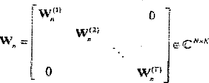
![]()
![]()
Unter
Bezugnahme auf ![]()
![]()
![]()
![]()
Unter
Bezugnahme auf ![]()
![]()
![]()
![]()
Das
Multiplizieren ![]()
![]()
![]()
![]()
Für jede Antenne
t wird der Chipvektor z( t )[n] in
Man
bemerkt, dass bei dieser Sendevariante die Rückge winnung der räumlichen
Diversität über den Code
G0 (in
Die Überlastbedingungen
und der explizite Aufbau der Matrix Wn können präzisiert
werden. Das System ist überlastet,
sobald:
Das bedeutet nicht unbedingt U > SF (das heißt, dass nicht notwendigerweise pro Antenne eine Überlast besteht).This does not necessarily mean U> S F (that is, there is not necessarily an overload per antenna).
Wenn U > SF, sind die verschiedenen Antennen einzeln überlastet. Die Ungleichheit T × U > SF wird daher trivial geprüft, und das System mit mehreren Antennen wird als komplett überlastet qualifiziert.If U> S F , the different antennas are individually overloaded. The inequality T × U> S F is therefore checked trivially, and the system with multiple antennas is qualified as completely overloaded.
Nun
wird das Ergebnis der polynomischen Division von U durch SF betrachtet:
Die U Benutzer, die zu jeder der Sendeantennen gehören, werden daher in A gesättigte Gruppen zu SF Benutzern verteilt, und 1 nicht gesättigte Gruppe zu B Benutzern.The U users belonging to each of the broadcasting antennas are therefore distributed in A saturated groups to S F users, and 1 non-saturated group to B users.
Man
setzt: 
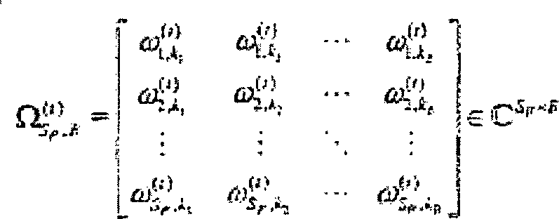
Eine
Matrix SF × SF,
die eine Gruppe von Spreizungscodes, einzeln, gebildet aus den SF orthogonalen Codes (zum Beispiel Hadamard-Matrix)
darstellt, die hinsicht lich des Aufbaus der folgenden Gleichmäßigkeit entspricht: ![]()
![]()
Eine
gekürzte
Version, die der Antenne t eigen ist, gebildet aus B willkürlich aus ![]()
![]()
![]()
![]()
Man
nennt Verwürfelungsmatrix
für die
gesättigte
Gruppe von Benutzern i = l, ..., A und man schreibt: 

Diese
Verwürfelungsmatrix,
die zu dem Block ![]()
![]()


![]()
![]()
Hinweis:
Aus offensichtlichen Einfachheitsgründen wurde in diesem Kapitel
ein Fall behandelt, bei dem die interne Codierungsmatrix Wn aus Blöcken ![]()
![]()
Dieser
Fall kann auf allgemeinere Fälle
erweitert werden, bei welchen die interne Codierungsmatrix Wn aus Blöcken
mit untereinander unterschiedlichen Maßen besteht und insbesondere
auf den allgemeineren Fall, in dem der Block ![]()
![]()
Die
Matrix Wn hat daher das Maß N × K mit ![]()
![]()
Man kann daher das Sendeverfahren an diese Variante anpassen.you can therefore adapt the transmission method to this variant.
1.7 Periodisches Spreizen1.7 Periodic spreading
Die
Verarbeitung ist hier identisch mit der in Kapitel 1.5 oder 1.6
ausgeführten,
mit der Ausnahme, dass die Erzeugungsmatrix hier periodisch in der
Zeit angewandt und wie folgt geschrieben wird:
1.8 Chip-Verschachteln1.8 chip nesting
Unter
Bezugnahme auf die
Nach
dem Spreizen pro Chip ![]()
![]()
![]()
![]()
MIMO-Kanals
bilden: ![]()
![]()
1.9 Spektrale Effizienz1.9 Spectral efficiency
Das
Sendeverfahren fällt
naturgemäß in die
allgemeine Klasse der Raum-Zeit-Codes. Die spektrale Effizienz des
Systems (in Bits pro Nutzung des Kanals) unter der Annahme eines
idealen Nyquist-Filters mit beschränktem Band ist gleich:
In der Praxis weist das Filter zum Formen beim Senden einen Überlauffaktor ε nicht gleich Null (roll-off) auf. Beim Empfang wendet man ein Filter, das an dieses Sendefilter angepasst ist, für alle Empfangsantennen an. Es wird angenommen, dass die Kanalschätzungs- und Rhythmussynchronisations- und Trägerwellensynchronisationsfunktionen derart ausgeführt werden, dass die Impulsantwortkoeffizienten des Kanals regelmäßig um einen Wert gleich der Chipzeit beabstandet sind (Kanal äquivalent in diskretem Basisband zur Chipzeit). Diese Annahme ist legitim, denn das Abtasttheorem von Shannon auferlegt ein Abtasten mit dem Rhythmus (1 + ε)/Tc, das durch 1/Tc angenähert werden kann, wenn ε klein ist.In practice, the filter for shaping on transmission has an overflow factor ε not equal to zero (roll-off). On reception, a filter adapted to this transmit filter is used for all receive antennas. It is assumed that the channel estimation and rhythm synchronization and carrier wave synchronization functions are performed such that the impulse response coefficients of the channel are regularly spaced by a value equal to the chip time (channel equivalent in discrete baseband at chip time). This assumption is legitimate because Shannon's sampling theorem imposes a sampling on the rhythm (1 + ε) / T c that can be approximated by 1 / T c when ε is small.
Man kann direkt Ausdrücke verallgemeinern, die auf ein Abtasten gleich einem Mehrfachen von 1/Tc folgen.One can directly generalize expressions that follow a sampling equal to a multiple of 1 / T c .
2. Kanalmodus2nd channel mode
Die Übertragung
erfolgt auf einem B-Blöcke-Kanal
mit mehrfachen Eingängen
und Ausgängen
(MIMO) in Frequenz selektiv: ![]()
![]()
Der
Kanal H(b) wird als auf Lx Chips
konstant mit der folgenden Vereinbarung angenommen:
Die Chipmatrix X kann in B Matrizen zu einzelnen Chips X(1), ..., X(B) mit dem Maß T × Lx segmentiert werden (bei Bedarf rechts und links durch physikalische Nullen oder Abstandszeiten ergänzt), wobei jede Matrix X( b) den Kanal H(b) sieht.The chip matrix X can be segmented in B matrices into individual chips X (1) ,..., X (B) with the dimension T × L x (if necessary, supplemented by physical zeros or spacings on the right and left), each matrix X ( b ) sees the channel H (b) .
Die
Extremfälle
des B-Blöcke-Modells
sind die Folgenden:
B = 1 und LX =
LSF quasi-statisches Modell
B = LSF und LX = 1 ergodisches
Modell (Chip)The extreme cases of the B-block model are the following:
B = 1 and L X = LS F quasi-static model
B = LS F and L X = 1 ergodic model (chip)
Eine Neunummerierung der Chips wird innerhalb jedes Blocks angewandt.A Renumbering of the chips is applied within each block.
Für jeden
Index eines Blocks b erlaubt es das in Basisband äquivalente
Kanalmodell mit diskreter Zeit (Chiprhythmus) die empfangenen Vektoren
y(b)[l] ∊ CR im
Augenblick Chip 1 in der folgenden Form zu schreiben: ![]()
![]()
![]()
![]()
![]()
![]()
![]()
![]()
![]()
![]()
3. Einzelträgerwellenübertragung auf MIMO-Kanal mit mehreren Bahnen (HSDPA)3. Single carrier wave transmission on MIMO channel with several tracks (HSDPA)
Es wird hier angenommen, dass der Durchsatz sehr hoch und die Dopplerfrequenz des Kanals gering ist, so dass LX ≫ SF. Für den HSDPA-Modus der Norm UMTS ist der Kanal quasi statisch, das heißt, wenn B = 1.It is assumed here that the throughput is very high and the Doppler frequency of the channel is low, so that L X »S F. For the HSDPA mode of the UMTS standard, the channel is quasi-static, that is, when B = 1.
4. Mehrfachträgerwellenübertragung auf MIMO-Kanal mit mehreren Bahnen (MC-CDMA)4. Multi-carrier wave transmission on MIMO channel with several tracks (MC-CDMA)
Das
lineare interne Codieren
Das erfindungsgemäße Senden betrifft nicht nur ein Verfahren, das seine Umsetzung erlaubt, sondern auch das System, das das Verfahren ausführen kann.The Send according to the invention concerns not only a procedure that allows its implementation, but also the system that can perform the procedure.
Claims (25)
Applications Claiming Priority (1)
| Application Number | Priority Date | Filing Date | Title |
|---|---|---|---|
| EP04291041A EP1589686B1 (en) | 2004-04-22 | 2004-04-22 | Transmission for CDMA communications system on MIMO channel |
Publications (2)
| Publication Number | Publication Date |
|---|---|
| DE602004008579D1 DE602004008579D1 (en) | 2007-10-11 |
| DE602004008579T2 true DE602004008579T2 (en) | 2008-05-15 |
Family
ID=34931047
Family Applications (1)
| Application Number | Title | Priority Date | Filing Date |
|---|---|---|---|
| DE602004008579T Expired - Lifetime DE602004008579T2 (en) | 2004-04-22 | 2004-04-22 | Transmission to the CDMA communication system through a MIMO channel |
Country Status (9)
| Country | Link |
|---|---|
| US (1) | US7885316B2 (en) |
| EP (1) | EP1589686B1 (en) |
| JP (1) | JP4809328B2 (en) |
| KR (1) | KR101107631B1 (en) |
| CN (1) | CN1973474B (en) |
| AT (1) | ATE372002T1 (en) |
| DE (1) | DE602004008579T2 (en) |
| ES (1) | ES2293180T3 (en) |
| WO (1) | WO2005114888A1 (en) |
Families Citing this family (11)
| Publication number | Priority date | Publication date | Assignee | Title |
|---|---|---|---|---|
| US20100189162A1 (en) * | 2006-09-06 | 2010-07-29 | Takashi Yoshimoto | Transmission-and-reception apparatus, transmission-and-reception system, and transmission-and-reception method |
| US8831042B2 (en) | 2007-03-29 | 2014-09-09 | Lg Electronics Inc. | Method of transmitting sounding reference signal in wireless communication system |
| WO2008156293A2 (en) | 2007-06-19 | 2008-12-24 | Lg Electronics Inc. | Method of transmitting sounding reference signal |
| EP2180629B1 (en) | 2007-08-14 | 2017-11-29 | LG Electronics Inc. | Method for acquiring resource region information for PHICH and method of receiving PDCCH |
| WO2009022790A1 (en) | 2007-08-14 | 2009-02-19 | Lg Electronics Inc. | Method of transmitting data in a wireless communication system |
| KR101397039B1 (en) | 2007-08-14 | 2014-05-20 | 엘지전자 주식회사 | Signal Transmission Method Using CDM Against The Effect Of Channel Estimation Error in Transmit Diversity System |
| KR101405974B1 (en) | 2007-08-16 | 2014-06-27 | 엘지전자 주식회사 | Methods for transmitting codewords in multiple input multiple output system |
| KR101507785B1 (en) | 2007-08-16 | 2015-04-03 | 엘지전자 주식회사 | A method for transmitting channel quality information in a MIMO (Multiple Input Multiple Output) system |
| US8995559B2 (en) | 2008-03-28 | 2015-03-31 | Qualcomm Incorporated | Signaling message transmission in a wireless communication network |
| KR101420177B1 (en) * | 2010-04-07 | 2014-07-17 | 알까뗄 루슨트 | Method and apparatus for feeding back and constructing correlation matrix in multi-input multi-output systems |
| DE102011079972B4 (en) * | 2011-07-28 | 2017-07-06 | Siemens Convergence Creators Gmbh | Method for transmitting information data |
Family Cites Families (15)
| Publication number | Priority date | Publication date | Assignee | Title |
|---|---|---|---|---|
| EP0931388B1 (en) * | 1996-08-29 | 2003-11-05 | Cisco Technology, Inc. | Spatio-temporal processing for communication |
| EP1035677A1 (en) * | 1999-03-10 | 2000-09-13 | Lucent Technologies Inc. | Code branch allocation for CDMA systems |
| US6351499B1 (en) * | 1999-12-15 | 2002-02-26 | Iospan Wireless, Inc. | Method and wireless systems using multiple antennas and adaptive control for maximizing a communication parameter |
| US20020154705A1 (en) * | 2000-03-22 | 2002-10-24 | Walton Jay R. | High efficiency high performance communications system employing multi-carrier modulation |
| US7068628B2 (en) * | 2000-05-22 | 2006-06-27 | At&T Corp. | MIMO OFDM system |
| US6879576B1 (en) | 2000-09-06 | 2005-04-12 | Qualcomm Incorporated | Method and apparatus for processing a physical channel with partial transport format information |
| EP1330888B1 (en) * | 2000-10-27 | 2008-01-09 | Nortel Networks Limited | Method of space-time coding and corresponding transmitter |
| FR2821217B1 (en) * | 2001-02-21 | 2003-04-25 | France Telecom | METHOD AND SYSTEM FOR ITERATIVE CODING-DECODING OF DIGITAL DATA STREAMS ENCODED BY SPATIO-TEMPORAL COMBINATIONS, IN MULTIPLE TRANSMISSION AND RECEPTION |
| US7133459B2 (en) * | 2001-05-01 | 2006-11-07 | Texas Instruments Incorporated | Space-time transmit diversity |
| JP4317008B2 (en) * | 2001-06-21 | 2009-08-19 | コーニンクレッカ フィリップス エレクトロニクス エヌ ヴィ | MIMO transmission system, transmission apparatus, reception apparatus and method in wireless network |
| US7170926B2 (en) * | 2001-11-29 | 2007-01-30 | Interdigital Technology Corporation | Efficient multiple input multiple output system for multi-path fading channels |
| US7542446B2 (en) * | 2002-07-31 | 2009-06-02 | Mitsubishi Electric Research Laboratories, Inc. | Space time transmit diversity with subgroup rate control and subgroup antenna selection in multi-input multi-output communications systems |
| KR100457188B1 (en) | 2002-10-07 | 2004-11-16 | 한국전자통신연구원 | Method and apparatus for mc/mc-ds dual-mode spreading for adaptive multicarrier code division multiple access system |
| DE60320250T2 (en) * | 2003-08-29 | 2008-07-10 | Mitsubishi Denki K.K. | Method for transmitting data in a telecommunication system |
| TWI264194B (en) * | 2004-02-06 | 2006-10-11 | Univ Nat Chiao Tung | Framework and method for multiple-input multiple-output (MIMO) multi-carrier code division multiple access communication system |
-
2004
- 2004-04-22 DE DE602004008579T patent/DE602004008579T2/en not_active Expired - Lifetime
- 2004-04-22 EP EP04291041A patent/EP1589686B1/en not_active Expired - Lifetime
- 2004-04-22 AT AT04291041T patent/ATE372002T1/en not_active IP Right Cessation
- 2004-04-22 ES ES04291041T patent/ES2293180T3/en not_active Expired - Lifetime
-
2005
- 2005-04-21 US US11/587,222 patent/US7885316B2/en active Active
- 2005-04-21 KR KR1020067024372A patent/KR101107631B1/en active IP Right Grant
- 2005-04-21 CN CN200580020550.9A patent/CN1973474B/en active Active
- 2005-04-21 WO PCT/EP2005/004411 patent/WO2005114888A1/en active Application Filing
- 2005-04-21 JP JP2007508866A patent/JP4809328B2/en active Active
Also Published As
| Publication number | Publication date |
|---|---|
| US7885316B2 (en) | 2011-02-08 |
| CN1973474A (en) | 2007-05-30 |
| JP4809328B2 (en) | 2011-11-09 |
| CN1973474B (en) | 2015-10-07 |
| KR20070038958A (en) | 2007-04-11 |
| KR101107631B1 (en) | 2012-01-25 |
| EP1589686B1 (en) | 2007-08-29 |
| EP1589686A1 (en) | 2005-10-26 |
| US20070206662A1 (en) | 2007-09-06 |
| ES2293180T3 (en) | 2008-03-16 |
| WO2005114888A1 (en) | 2005-12-01 |
| WO2005114888A8 (en) | 2007-06-21 |
| JP2007534246A (en) | 2007-11-22 |
| DE602004008579D1 (en) | 2007-10-11 |
| ATE372002T1 (en) | 2007-09-15 |
Similar Documents
| Publication | Publication Date | Title |
|---|---|---|
| DE69838824T2 (en) | Method and device for transmitting data in a multicarrier transmission system | |
| DE69929788T2 (en) | METHOD AND DEVICE FOR DIVERSITY TRANSMISSION | |
| DE602004013462T2 (en) | BROADCAST TRANSMISSION WITH SPATIAL SPREAD IN A MULTIPLE COMMUNICATION SYSTEM | |
| DE60224672T2 (en) | TRANSMISSION METHOD AND DEVICE IN A RADIO COMMUNICATION NETWORK | |
| DE10237868B4 (en) | Apparatus and method for transmitting and receiving data using an antenna array in a mobile communication system | |
| EP2289213B1 (en) | Apparatus for assigning and assessing transmission symbols | |
| DE69434353T2 (en) | Multi-carrier frequency hopping communication system | |
| DE60215811T3 (en) | METHOD AND DEVICE FOR PROCESSING DATA FOR TRANSMISSION IN A MULTICHANNEL COMMUNICATION SYSTEM USING SELECTIVE CHANNEL INVERSION | |
| DE602005005115T2 (en) | Method and arrangement for combined wireless broadband communications | |
| DE69925173T2 (en) | Channel coding method and apparatus and data transmission apparatus in a CDMA communication system | |
| DE60211705T2 (en) | METHOD AND DEVICE FOR PROCESSING DATA FOR TRANSMISSION IN A MULTI-CHANNEL COMMUNICATION SYSTEM USING A SELECTIVE CHANNEL TRANSMISSION | |
| DE602004006817T2 (en) | Device and method for assigning subcarriers in a MIMO OFDM system | |
| DE60035439T2 (en) | DIFFERENTIAL ROOM TIME BLOCK CODING | |
| DE69921207T2 (en) | Multi-carrier CDMA transmission system with frequency and space diversity | |
| DE60215813T2 (en) | Radio communication system with transmit diversity and multi-user diversity | |
| DE60121476T2 (en) | TRANSMITTER FOR A WIRELESS COMMUNICATION SYSTEM WITH A VARIETY OF CODES AND ANTENNAS | |
| DE60005374T2 (en) | OFDM system with transmitter antenna diversity and pre-equalization | |
| EP2445136B1 (en) | Method for generating transmission signals or OFDM symbols in a communication system and communication system device | |
| DE602004008579T2 (en) | Transmission to the CDMA communication system through a MIMO channel | |
| DE69922116T2 (en) | Spread spectrum / receiver | |
| DE602004001576T2 (en) | Method for transmitting data in a telecommunication system with at least one transmitter | |
| DE69835087T2 (en) | Receiver architecture for a multiple scrambling code CDMA transmission method | |
| DE60316477T2 (en) | DEVICE AND METHOD FOR PRE-CODING A MULTI SUCH SIGNAL | |
| DE60318291T2 (en) | Apparatus and method for transmitting and receiving coded signals with multiple antennas in mobile communication systems | |
| DE60208200T2 (en) | Radio communication system with transmit diversity and multi-user diversity |
Legal Events
| Date | Code | Title | Description |
|---|---|---|---|
| 8364 | No opposition during term of opposition |