DE4433552B4 - Electronic HF dimmer for high and low voltage light bulbs - Google Patents
Electronic HF dimmer for high and low voltage light bulbs Download PDFInfo
- Publication number
- DE4433552B4 DE4433552B4 DE4433552A DE4433552A DE4433552B4 DE 4433552 B4 DE4433552 B4 DE 4433552B4 DE 4433552 A DE4433552 A DE 4433552A DE 4433552 A DE4433552 A DE 4433552A DE 4433552 B4 DE4433552 B4 DE 4433552B4
- Authority
- DE
- Germany
- Prior art keywords
- voltage
- electronic
- dimmer
- pwm
- switches
- Prior art date
- Legal status (The legal status is an assumption and is not a legal conclusion. Google has not performed a legal analysis and makes no representation as to the accuracy of the status listed.)
- Expired - Fee Related
Links
Classifications
-
- H—ELECTRICITY
- H02—GENERATION; CONVERSION OR DISTRIBUTION OF ELECTRIC POWER
- H02M—APPARATUS FOR CONVERSION BETWEEN AC AND AC, BETWEEN AC AND DC, OR BETWEEN DC AND DC, AND FOR USE WITH MAINS OR SIMILAR POWER SUPPLY SYSTEMS; CONVERSION OF DC OR AC INPUT POWER INTO SURGE OUTPUT POWER; CONTROL OR REGULATION THEREOF
- H02M1/00—Details of apparatus for conversion
- H02M1/42—Circuits or arrangements for compensating for or adjusting power factor in converters or inverters
- H02M1/4208—Arrangements for improving power factor of AC input
- H02M1/425—Arrangements for improving power factor of AC input using a single converter stage both for correction of AC input power factor and generation of a high frequency AC output voltage
-
- H—ELECTRICITY
- H05—ELECTRIC TECHNIQUES NOT OTHERWISE PROVIDED FOR
- H05B—ELECTRIC HEATING; ELECTRIC LIGHT SOURCES NOT OTHERWISE PROVIDED FOR; CIRCUIT ARRANGEMENTS FOR ELECTRIC LIGHT SOURCES, IN GENERAL
- H05B39/00—Circuit arrangements or apparatus for operating incandescent light sources
- H05B39/04—Controlling
- H05B39/041—Controlling the light-intensity of the source
- H05B39/044—Controlling the light-intensity of the source continuously
- H05B39/045—Controlling the light-intensity of the source continuously with high-frequency bridge converters
-
- H—ELECTRICITY
- H05—ELECTRIC TECHNIQUES NOT OTHERWISE PROVIDED FOR
- H05B—ELECTRIC HEATING; ELECTRIC LIGHT SOURCES NOT OTHERWISE PROVIDED FOR; CIRCUIT ARRANGEMENTS FOR ELECTRIC LIGHT SOURCES, IN GENERAL
- H05B39/00—Circuit arrangements or apparatus for operating incandescent light sources
- H05B39/04—Controlling
- H05B39/041—Controlling the light-intensity of the source
- H05B39/044—Controlling the light-intensity of the source continuously
- H05B39/047—Controlling the light-intensity of the source continuously with pulse width modulation from a DC power source
-
- Y—GENERAL TAGGING OF NEW TECHNOLOGICAL DEVELOPMENTS; GENERAL TAGGING OF CROSS-SECTIONAL TECHNOLOGIES SPANNING OVER SEVERAL SECTIONS OF THE IPC; TECHNICAL SUBJECTS COVERED BY FORMER USPC CROSS-REFERENCE ART COLLECTIONS [XRACs] AND DIGESTS
- Y02—TECHNOLOGIES OR APPLICATIONS FOR MITIGATION OR ADAPTATION AGAINST CLIMATE CHANGE
- Y02B—CLIMATE CHANGE MITIGATION TECHNOLOGIES RELATED TO BUILDINGS, e.g. HOUSING, HOUSE APPLIANCES OR RELATED END-USER APPLICATIONS
- Y02B20/00—Energy efficient lighting technologies, e.g. halogen lamps or gas discharge lamps
-
- Y—GENERAL TAGGING OF NEW TECHNOLOGICAL DEVELOPMENTS; GENERAL TAGGING OF CROSS-SECTIONAL TECHNOLOGIES SPANNING OVER SEVERAL SECTIONS OF THE IPC; TECHNICAL SUBJECTS COVERED BY FORMER USPC CROSS-REFERENCE ART COLLECTIONS [XRACs] AND DIGESTS
- Y02—TECHNOLOGIES OR APPLICATIONS FOR MITIGATION OR ADAPTATION AGAINST CLIMATE CHANGE
- Y02B—CLIMATE CHANGE MITIGATION TECHNOLOGIES RELATED TO BUILDINGS, e.g. HOUSING, HOUSE APPLIANCES OR RELATED END-USER APPLICATIONS
- Y02B70/00—Technologies for an efficient end-user side electric power management and consumption
- Y02B70/10—Technologies improving the efficiency by using switched-mode power supplies [SMPS], i.e. efficient power electronics conversion e.g. power factor correction or reduction of losses in power supplies or efficient standby modes
Landscapes
- Engineering & Computer Science (AREA)
- Power Engineering (AREA)
- Circuit Arrangement For Electric Light Sources In General (AREA)
Abstract
Elektronischer HF-Dimmer zum Betreiben und Dimmen von Hochvolt-Glühlampen mit hohem Leistungsfaktor und geringen Netzstrom-Oberschwingungen, bestehend aus einem Funkenstörfilter (1), einem Zweiweggleichrichter (2), einem Spannungswandler zur Erzeugung einer IC-Versorgungsspannung (3), einem HF-Generator (4) mit integriertem Pulsweiten-Modulator (PWM), der vier Halbleiterschalter (S1 bis S4) in Vollbrückenanordnung mit gleichem Tastverhältnis ansteuert, wobei zwei diagonal gegenüberliegende Schalter (S2, S3) vom PWM-Signal gleichphasig und die anderen diagonal gegenüberliegenden Schalter (S1, S4) vom invertierten PWM-Signal gegenphasig angesteuert werden und die Hochvolt-Glühlampe (L1) in der Brückendiagonalen (A, B) liegt.Electronic HF dimmer for operating and dimming high-voltage light bulbs with a high power factor and low mains current harmonics, consisting of a spark interference filter (1), a two-way rectifier (2), a voltage converter for generating an IC supply voltage (3), an HF Generator (4) with integrated pulse width modulator (PWM), which controls four semiconductor switches (S1 to S4) in full bridge arrangement with the same pulse duty factor, whereby two diagonally opposite switches (S2, S3) are in phase from the PWM signal and the other diagonally opposite switches ( S1, S4) are driven in phase opposition by the inverted PWM signal and the high-voltage incandescent lamp (L1) lies in the bridge diagonal (A, B).
Description
Unter Netzrückwirkung versteht man die Wirkung von nichtsinusförmigen Verbraucherströmen am Innenwiderstand (Generator und Leitungen) des speisenden Netzes mit der Folge einer unerwünschten Spannungsverzerrung (Abweichung von der Sinusform) der Netzspannung. Ein hoher Leistungsfaktor (λ ≈ 1) reduziert die Blindströme und damit die ohmschen Verluste in den Netzleitungen der Stromversorgungsunternehmen.Network feedback is understood to mean Effect of non-sinusoidal Consumer flows on Internal resistance (generator and lines) of the supply network resulting in an undesirable Voltage distortion (deviation from the sine shape) of the mains voltage. A high power factor (λ ≈ 1) reduces the reactive currents and thus the ohmic losses in the power supply companies' power lines.
Verbraucher mit nichtsinusförmiger, impulsförmiger Stromaufnahme sind z. B.: TV-Empfänger, HiFi-Geräte, Computer, Meß-, Steuer- und Regelgeräte, Dimmer für Glühlampen, dimmbare elektronische Transformatoren für Niedervolt-Halngenglühlampen, einfache elektronische Entladungslampenvorschaltgeräte ohne passive oder aktive Oberschwingungsbegrenzungsfilter, sowie eine Vielzahl von Geräten, wo Phasenanschnitt- bzw. Abschnittsteuerungen mit Halbleiterbauelementen der Leistungselektronik zur Anwendung kommen.Consumers with non-sinusoidal, pulsed Current consumption are e.g. E.g .: TV receivers, HiFi devices, computers, measuring, Control and regulating devices, Dimmer for Lightbulbs, dimmable electronic transformers for low-voltage halogen lamps, simple electronic discharge lamp ballasts without passive or active harmonic limitation filter, as well as a Variety of devices, where phase gating or section controls with semiconductor components power electronics are used.
Bei modernen elektronischen HF-Dimmern (EHFD) für Lampen sind daher ein Leistungsfaktor 1 und ein geringer Oberschwingungsgehalt anzustreben. Beides kann mit konventionellen Schaltnetzteilen – welche pulsförmige Ströme aufnehmen – nicht erreicht werden.With modern electronic HF dimmers (EHFD) for lamps are therefore a power factor 1 and a low harmonic content desirable. Both can be done with conventional switching power supplies - which pulsed streams record - not reached become.
Elektronische HF-Dimmer für Lampen senken die Energiekosten für die Beleuchtung und schonen die Umwelt durch Reduzierung von Kraftwerksemissionen.Electronic HF dimmers for lamps reduce energy costs for the lighting and protect the environment by reducing power plant emissions.
Der Stand der Technik geht aus nachfolgenden Veröffentlichungen hervor:
- 1. STURM, C. H.; KLEIN, E.: Betriebsgeräte und Schaltungen für elektrische Lampen: Vorschaltgeräte, Transformatoren, Starter, Lampen und Leuchten, Normen. 6., neubearb. Aufl. Berlin (u. a.): Siemens-Aktienges., 1992, S. 295–304, ISBN: 3-8009-1586-3
- 2. LIMANN, O; PELKA, H: Elektronik ohne Ballast. 7., neu bearb. Aufl. München; Franzis, 1987, S. 458, ISBN 3-7723-5617-6
- 3. SÖYLEMEZ, A. I.: Gegentakt-Schaltnetzteil mit IGBTs. In: Elektronik, 1990, H. 22, S. 196–203
- 4.
EP 0 460 736 A1 - 5. QUINN, H. P.: POWER REGULATOR FOR A RESISTIVE LOAD. In: XEROX DISCLOSURE JOURNAL, Vol. 3, Nov/Dec 1978
- 1. STORM, CH; KLEIN, E .: Control gear and circuits for electric lamps: ballasts, transformers, starters, lamps and lights, standards. 6th, new editing. Aufl. Berlin (among others): Siemens-Aktienges., 1992, pp. 295-304, ISBN: 3-8009-1586-3
- 2. LIMANN, O; PELKA, H: Electronics without ballast. 7th, reprocess Aufl. Munich; Franzis, 1987, p. 458, ISBN 3-7723-5617-6
- 3. SÖYLEMEZ, AI: push-pull switching power supply with IGBTs. In: Elektronik, 1990, H. 22, pp. 196-203
- 4th
EP 0 460 736 A1 - 5. QUINN, HP: POWER REGULATOR FOR A RESISTIVE LOAD. In: XEROX DISCLOSURE JOURNAL, Vol. 3, Nov / Dec 1978
In 1 werden elektronische Transformatoren für Niedervolt-Glühlampen beschrieben.1 shows electronic transformers for low-voltage incandescent lamps described.
In 2 sind Auswahlkriterien für Durchflusswandler- und Sperrwandler-Varianten angegeben.2 shows selection criteria for flow converter and flyback converter variants specified.
In 3 wird ein PWM-Gegentakt-Schaltnetzteil als Dimmschaltung für Niedervolt-Glühlampen beschrieben.3 shows a PWM push-pull switching power supply as Dimming circuit for Low-voltage bulbs described.
In 4 wird ein elektronischer Transformator für Niedervolt-Glühlampen mit einer Stabilisierungsschaltung für die Lampenspannung erläutert.4 is an electronic transformer for low-voltage incandescent lamps explained with a stabilizing circuit for the lamp voltage.
In 5 ist ein Leistungsregler für eine ohmsche Last (z. B. Glühlampe) angegeben, wobei die Regelung durch einen PWM-Regler erfolgt.5 is a power controller for an ohmic load (e.g. incandescent lamp), where the Regulation by a PWM controller.
In
Sollen Hochvoltglühlampen (z. B. für 230 V) gedimmt werden, kann diese einfache Schaltung verwendet werden, die ebenfalls beim Dimmen dem Netz einen weitestgehend sinusförmigen Strom entnimmt, der mit der Netzspannung in Phase ist.If high-voltage incandescent lamps (e.g. for 230 V) dimmed this simple circuit can also be used when dimming takes a largely sinusoidal current from the network, which is in phase with the mains voltage.
Zum Dimmen der Glühlampe L (ohmsche Last) genügt ein Halbleiterschalter S. Die HF-Spannung wird sinusförmig moduliert und der gefilterte, dem Netz entnommene Strom ist wiederum weitestgehend sinusförmig, d. h., diese Dimmschaltung wirkt gegenüber dem speisenden Netz wie ein quasi "ohmscher Verbraucher", wobei der Leistungsfaktor sehr hoch und der Oberschwingungsgehalt des aufgenommenen Netzstroms sehr gering ist.A semiconductor switch is sufficient to dim the incandescent lamp L (ohmic load) S. The RF voltage becomes sinusoidal modulated and the filtered current drawn from the network is again largely sinusoidal, d. that is, this dimming circuit works against the feeding network like a quasi "ohmic Consumer ", whereby the power factor is very high and the harmonic content of the recorded mains current is very low.
Die erfindungsgemäße Aufgabe ist die Realisierung eines elektronischen HF-Dimmers zum Betrieb von Hochvoltglühlampen mit sehr hohem Leistungsfaktor und äußerst geringen Netzstromoberschwingungen. Diese Aufgabe wird durch einen Gegenstand mit den Merkmalen des Patentanspruchs 1 gelöst. Vorteilhafte Ausgestaltungen sind in den Unteransprüchen angegeben.The object of the invention is the realization of an electronic HF dimmer for operating high-voltage incandescent lamps with a very high power factor and extremely low mains harmonics. This task is accomplished by an object with the characteristics of Claim 1 solved. Advantageous refinements are specified in the subclaims.
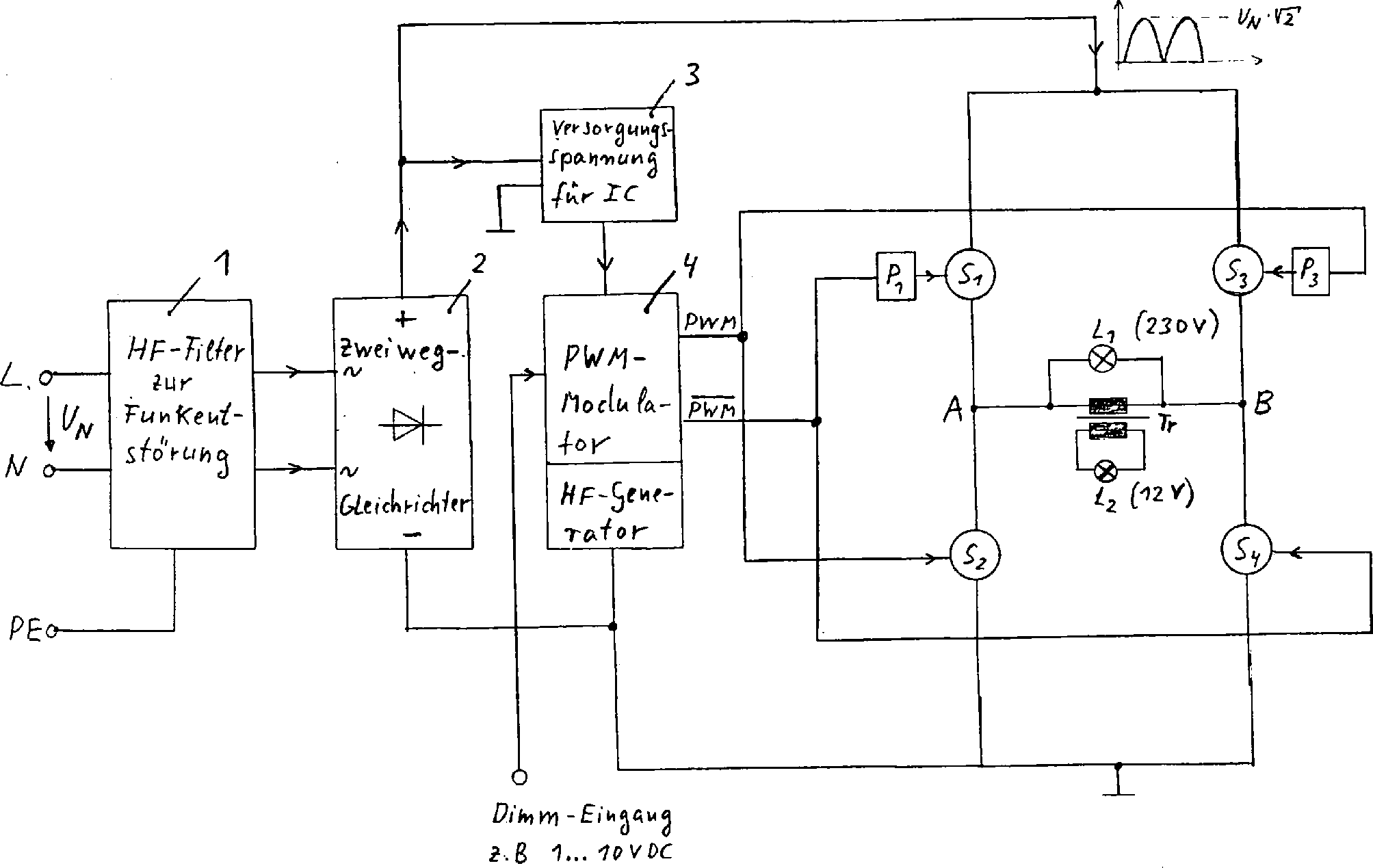
Die Erfindung wird anhand des Schaltplans in
Die Netzspannung gelangt nach
Die Ansteuerung der vier Halbleiterschalter erfolgt
mit einem HF-Generator mit integriertem Pulsweitenmodulator (PWM)
Der Pulsweitenmodulator erzeugt zwei gegenphasige Rechtecksignale mit variablem Tastverhältnis (PWM und PWM), wobei das PWM-Signal die Schalter S2 und S3 gleichphasig und das invertierte PWM-Signal die Schalter S1 und S4 gleichphasig ansteuern. Die notwendige Potentialtrennung für die Halbleiterschalter S1 und S3 geschieht durch die Potentialtrennbauelemente P1 und P3 (z. B. Impuls-Übertrager, Optokoppler, Hochvolttreiber-IC usw.).The pulse width modulator generates two square-phase signals with a variable pulse duty factor (PWM and PWM), the PWM signal triggering the switches S2 and S3 in phase and the inverted PWM signal triggering the switches S1 and S4 in phase. The potential isolation required for the semiconductor switches S1 and S3 occurs through the potential isolation components P1 and P3 (e.g. Im pulse transformer, optocoupler, high-voltage driver IC, etc.).
Es ergibt sich bei dieser Betriebsweise in der Brückendiagonalen (A. . .B) eine mit der Netzspannung (50 Hz) modulierte HF-Spannung (z. B. 40 kHz) mit variabler Pulsbreite, wodurch ein Dimmen ermöglicht wird.It results from this mode of operation in the bridge diagonal (A. .B.) one modulated with the mains voltage (50 Hz) HF voltage (e.g. 40 kHz) with variable pulse width, which enables dimming.
Durch die vollkommen symmetrische PWM-Steuerung der Vollbrücke ist der HF-Verbraucherstrom durch Hochvoltglühlampen L1 öder HF-Transformatoren Tr mit sekundärseitig angeschlossenen Niedervoltglühlampen L2 in der Brückendiagonalen gleichfalls sinusförmig moduliert mit dem großen Vorteil, daß – auch beim Dimmen – der über das Funkentstörfilter geglättete 50 Hz-Netzstrom weitestgehend sinusförmig und nahezu in Phase mit der Netzspannung ist.Thanks to the completely symmetrical PWM control the full bridge is the HF consumer current by high-voltage light bulbs L1 or HF transformers Door with secondary connected low-voltage light bulbs L2 in the bridge diagonal also sinusoidal modulates with the big one Advantage that - even with Dimming - the one about that RFI smoothed 50 Hz mains current largely sinusoidal and is almost in phase with the mains voltage.
Claims (6)
Priority Applications (3)
| Application Number | Priority Date | Filing Date | Title |
|---|---|---|---|
| DE4433552A DE4433552B4 (en) | 1994-09-06 | 1994-09-06 | Electronic HF dimmer for high and low voltage light bulbs |
| AU34698/95A AU3469895A (en) | 1994-09-06 | 1995-09-06 | Electronic h.f. dimmer for high voltage and low voltage incandescent lamps |
| PCT/DE1995/001265 WO1996008123A2 (en) | 1994-09-06 | 1995-09-06 | Electronic h.f. dimmer for high voltage and low voltage incandescent lamps |
Applications Claiming Priority (1)
| Application Number | Priority Date | Filing Date | Title |
|---|---|---|---|
| DE4433552A DE4433552B4 (en) | 1994-09-06 | 1994-09-06 | Electronic HF dimmer for high and low voltage light bulbs |
Publications (2)
| Publication Number | Publication Date |
|---|---|
| DE4433552A1 DE4433552A1 (en) | 1996-03-07 |
| DE4433552B4 true DE4433552B4 (en) | 2004-01-15 |
Family
ID=6528726
Family Applications (1)
| Application Number | Title | Priority Date | Filing Date |
|---|---|---|---|
| DE4433552A Expired - Fee Related DE4433552B4 (en) | 1994-09-06 | 1994-09-06 | Electronic HF dimmer for high and low voltage light bulbs |
Country Status (3)
| Country | Link |
|---|---|
| AU (1) | AU3469895A (en) |
| DE (1) | DE4433552B4 (en) |
| WO (1) | WO1996008123A2 (en) |
Cited By (1)
| Publication number | Priority date | Publication date | Assignee | Title |
|---|---|---|---|---|
| WO2008028563A1 (en) * | 2006-09-08 | 2008-03-13 | Schiederwerk Mbz Telekommunikation Gmbh & Co. Kg | Dimmer circuit |
Families Citing this family (5)
| Publication number | Priority date | Publication date | Assignee | Title |
|---|---|---|---|---|
| US5661645A (en) * | 1996-06-27 | 1997-08-26 | Hochstein; Peter A. | Power supply for light emitting diode array |
| DE19729705A1 (en) * | 1997-07-11 | 1999-01-14 | Philips Patentverwaltung | Circuit arrangement for feeding a load |
| DE10012363A1 (en) * | 2000-03-14 | 2001-10-11 | Tridonic Bauelemente | Electronic transformer |
| DE102006013692A1 (en) * | 2006-03-24 | 2007-10-04 | Handlbauer, Gerhard | Dimmer for controlling light source active at low voltage, has housing, free from manually operated switching or adjusting equipment, comprising infrared signal receiver influenced by signals of remote control transmitter |
| KR101001241B1 (en) | 2008-09-05 | 2010-12-17 | 서울반도체 주식회사 | Ac led dimmer and dimming method thereby |
Citations (1)
| Publication number | Priority date | Publication date | Assignee | Title |
|---|---|---|---|---|
| EP0460736A1 (en) * | 1990-06-07 | 1991-12-11 | Waters Beheer B.V. | An electronic transformer for low voltage lamps with lamp voltage stabilisation |
Family Cites Families (1)
| Publication number | Priority date | Publication date | Assignee | Title |
|---|---|---|---|---|
| AT399073B (en) * | 1990-10-11 | 1995-03-27 | Hermann Hans | METHOD FOR OPERATING AN INVERTER-CONTROLLED BRIDGE CIRCUIT AND BRIDGE CIRCUIT FOR IMPLEMENTING THE METHOD |
-
1994
- 1994-09-06 DE DE4433552A patent/DE4433552B4/en not_active Expired - Fee Related
-
1995
- 1995-09-06 AU AU34698/95A patent/AU3469895A/en not_active Abandoned
- 1995-09-06 WO PCT/DE1995/001265 patent/WO1996008123A2/en active Application Filing
Patent Citations (1)
| Publication number | Priority date | Publication date | Assignee | Title |
|---|---|---|---|---|
| EP0460736A1 (en) * | 1990-06-07 | 1991-12-11 | Waters Beheer B.V. | An electronic transformer for low voltage lamps with lamp voltage stabilisation |
Non-Patent Citations (6)
| Title |
|---|
| LIMANN,O., PELKA,H: Elektronik ohne Ballast. 7., neu bearb. Aufl. München: Franzis, 1987, S. 458, ISBN 3-7723-5617-6 * |
| QUINN,H.P.: POWER REGULATOR FOR A RESISTIVE LOAD. In: XEROX DISCLOSURE JOURNAL, Vol. 3, Nr. 6, Nov/Dec 1978 * |
| SÖYLEMEZ,A.I.: Gegentakt-Schaltnetzteil mit IGBTs. In: Elektronik, 1990, H. 22, S. 196-203 |
| SÖYLEMEZ,A.I.: Gegentakt-Schaltnetzteil mit IGBTs.In: Elektronik, 1990, H. 22, S. 196-203 * |
| STURM,C.H., KLEIN,E.: Betriebsgeräte und Schaltungen für elektrische Lampen: Vorschaltger- äte, Transformatoren, Starter, Lampen und Leuchter Normen. 6., neubearb. Aufl. Berlin [u.a.]: Siemens AG 1992, S. 295-304, ISBN: 3-8009-1586-3 |
| STURM,C.H., KLEIN,E.: Betriebsgeräte und Schaltungen für elektrische Lampen: Vorschaltger- äte, Transformatoren, Starter, Lampen und LeuchterNormen. 6., neubearb. Aufl. Berlin [u.a.]: Siemens AG 1992, S. 295-304, ISBN: 3-8009-1586-3 * |
Cited By (2)
| Publication number | Priority date | Publication date | Assignee | Title |
|---|---|---|---|---|
| WO2008028563A1 (en) * | 2006-09-08 | 2008-03-13 | Schiederwerk Mbz Telekommunikation Gmbh & Co. Kg | Dimmer circuit |
| DE202007018812U1 (en) | 2006-09-08 | 2009-07-16 | Schiederwerk Mbz Telekommunikation Gmbh & Co Kg | dimmer circuit |
Also Published As
| Publication number | Publication date |
|---|---|
| WO1996008123A3 (en) | 1996-05-17 |
| AU3469895A (en) | 1996-03-27 |
| DE4433552A1 (en) | 1996-03-07 |
| WO1996008123A2 (en) | 1996-03-14 |
Similar Documents
| Publication | Publication Date | Title |
|---|---|---|
| DE60207113T2 (en) | LAMP TRANSFORMER FOR USE WITH AN ELECTRONIC DIMMER AND METHOD FOR USE THEREOF TO REDUCE ACOUSTIC NOISE | |
| EP0264765B1 (en) | Circuit arrangement for operating low-voltage halogen incandescent lamps | |
| EP0244644B1 (en) | Circuit arrangement for the high-frequency operation of low-pressure discharge lamps | |
| DE3829388A1 (en) | CIRCUIT ARRANGEMENT FOR OPERATING A LOAD | |
| DE102004047399A1 (en) | Simplified topology for HID lamps | |
| DE19821351A1 (en) | Circuit arrangement for operating electric lamps | |
| EP0439240B1 (en) | Electronic ballast | |
| EP0825806B1 (en) | Circuit for operating incandescent lamps | |
| DE69831666T2 (en) | LOW VOLTAGE LIGHTING SYSTEM | |
| US20070057640A1 (en) | Apparatus and method for providing dimming control of lamps and electrical lighting systems | |
| DE4433552B4 (en) | Electronic HF dimmer for high and low voltage light bulbs | |
| EP1467474A2 (en) | Interface circuit for operation of capacitive loads | |
| DE60217044T2 (en) | Dimming control system for electronic ballasts | |
| WO2014075116A2 (en) | Converter module for the phase dimming of leds | |
| KR100615745B1 (en) | Wave shaping circuit | |
| EP0697803A2 (en) | Circuit for operating discharge lamps | |
| DE19613703C2 (en) | Circuit arrangement for dimming an electronic transformer | |
| DE19903015A1 (en) | Dimmable ballast apparatus for cold cathode fluorescent lamps, has controllable voltage source as pulse width/frequency controllable AC generator with output is supplied to intermediate tapping of first part-winding. | |
| DE2910492A1 (en) | POWER SUPPLY CIRCUIT WITH TWO POWER LEVELS | |
| DE102008000027B4 (en) | Electronic ballast and circuit arrangement for dimming gas discharge lamps | |
| DE10253245B4 (en) | Method and device for generating a supply voltage for lighting means | |
| EP0671867B1 (en) | Circuit for operating a discharge lamp | |
| WO2004015865A1 (en) | Circuit arrangement for controlling two independent load resistors that can be operated with a rectified alternating current voltage | |
| DE2303553A1 (en) | ELECTRONIC SWITCHING DEVICE | |
| DE4328306A1 (en) | Circuit for HF operation for low presence discharge lamps - has rectifier and inverter and several opto-couplers, with controlled load circuit |
Legal Events
| Date | Code | Title | Description |
|---|---|---|---|
| 8122 | Nonbinding interest in granting licences declared | ||
| 8120 | Willingness to grant licences paragraph 23 | ||
| 8110 | Request for examination paragraph 44 | ||
| 8364 | No opposition during term of opposition | ||
| 8339 | Ceased/non-payment of the annual fee |