DE202011000341U1 - Lock for a flap or door - Google Patents
Lock for a flap or door Download PDFInfo
- Publication number
- DE202011000341U1 DE202011000341U1 DE201120000341 DE202011000341U DE202011000341U1 DE 202011000341 U1 DE202011000341 U1 DE 202011000341U1 DE 201120000341 DE201120000341 DE 201120000341 DE 202011000341 U DE202011000341 U DE 202011000341U DE 202011000341 U1 DE202011000341 U1 DE 202011000341U1
- Authority
- DE
- Germany
- Prior art keywords
- spring
- lock
- catch
- pawl
- stop
- Prior art date
- Legal status (The legal status is an assumption and is not a legal conclusion. Google has not performed a legal analysis and makes no representation as to the accuracy of the status listed.)
- Expired - Lifetime
Links
- 230000000903 blocking effect Effects 0.000 claims description 17
- 210000003746 feather Anatomy 0.000 claims description 12
- 239000002184 metal Substances 0.000 claims description 6
- 238000001746 injection moulding Methods 0.000 description 3
- 210000001331 nose Anatomy 0.000 description 3
- 238000004519 manufacturing process Methods 0.000 description 2
- BUHVIAUBTBOHAG-FOYDDCNASA-N (2r,3r,4s,5r)-2-[6-[[2-(3,5-dimethoxyphenyl)-2-(2-methylphenyl)ethyl]amino]purin-9-yl]-5-(hydroxymethyl)oxolane-3,4-diol Chemical compound COC1=CC(OC)=CC(C(CNC=2C=3N=CN(C=3N=CN=2)[C@H]2[C@@H]([C@H](O)[C@@H](CO)O2)O)C=2C(=CC=CC=2)C)=C1 BUHVIAUBTBOHAG-FOYDDCNASA-N 0.000 description 1
- 210000003128 head Anatomy 0.000 description 1
- 238000009434 installation Methods 0.000 description 1
- JEIPFZHSYJVQDO-UHFFFAOYSA-N iron(III) oxide Inorganic materials O=[Fe]O[Fe]=O JEIPFZHSYJVQDO-UHFFFAOYSA-N 0.000 description 1
Images


Classifications
-
- E—FIXED CONSTRUCTIONS
- E05—LOCKS; KEYS; WINDOW OR DOOR FITTINGS; SAFES
- E05B—LOCKS; ACCESSORIES THEREFOR; HANDCUFFS
- E05B79/00—Mounting or connecting vehicle locks or parts thereof
- E05B79/10—Connections between movable lock parts
- E05B79/12—Connections between movable lock parts using connecting rods
- E05B79/16—Connections between movable lock parts using connecting rods characterised by the means for linking the rods to other lock parts, e.g. to levers
-
- E—FIXED CONSTRUCTIONS
- E05—LOCKS; KEYS; WINDOW OR DOOR FITTINGS; SAFES
- E05B—LOCKS; ACCESSORIES THEREFOR; HANDCUFFS
- E05B15/00—Other details of locks; Parts for engagement by bolts of fastening devices
- E05B15/04—Spring arrangements in locks
-
- E—FIXED CONSTRUCTIONS
- E05—LOCKS; KEYS; WINDOW OR DOOR FITTINGS; SAFES
- E05B—LOCKS; ACCESSORIES THEREFOR; HANDCUFFS
- E05B79/00—Mounting or connecting vehicle locks or parts thereof
- E05B79/02—Mounting of vehicle locks or parts thereof
- E05B79/08—Mounting of individual lock elements in the lock, e.g. levers
-
- E—FIXED CONSTRUCTIONS
- E05—LOCKS; KEYS; WINDOW OR DOOR FITTINGS; SAFES
- E05B—LOCKS; ACCESSORIES THEREFOR; HANDCUFFS
- E05B85/00—Details of vehicle locks not provided for in groups E05B77/00 - E05B83/00
- E05B85/02—Lock casings
-
- E—FIXED CONSTRUCTIONS
- E05—LOCKS; KEYS; WINDOW OR DOOR FITTINGS; SAFES
- E05B—LOCKS; ACCESSORIES THEREFOR; HANDCUFFS
- E05B85/00—Details of vehicle locks not provided for in groups E05B77/00 - E05B83/00
- E05B85/20—Bolts or detents
- E05B85/24—Bolts rotating about an axis
-
- E—FIXED CONSTRUCTIONS
- E05—LOCKS; KEYS; WINDOW OR DOOR FITTINGS; SAFES
- E05B—LOCKS; ACCESSORIES THEREFOR; HANDCUFFS
- E05B85/00—Details of vehicle locks not provided for in groups E05B77/00 - E05B83/00
- E05B85/20—Bolts or detents
- E05B85/24—Bolts rotating about an axis
- E05B85/26—Cooperation between bolts and detents
-
- E—FIXED CONSTRUCTIONS
- E05—LOCKS; KEYS; WINDOW OR DOOR FITTINGS; SAFES
- E05B—LOCKS; ACCESSORIES THEREFOR; HANDCUFFS
- E05B15/00—Other details of locks; Parts for engagement by bolts of fastening devices
- E05B15/04—Spring arrangements in locks
- E05B2015/0403—Wound springs
- E05B2015/0406—Wound springs wound in a cylindrical shape
- E05B2015/041—Wound springs wound in a cylindrical shape loaded perpendicular to cylinder axis
-
- E—FIXED CONSTRUCTIONS
- E05—LOCKS; KEYS; WINDOW OR DOOR FITTINGS; SAFES
- E05B—LOCKS; ACCESSORIES THEREFOR; HANDCUFFS
- E05B15/00—Other details of locks; Parts for engagement by bolts of fastening devices
- E05B15/04—Spring arrangements in locks
- E05B2015/0437—Attachments or mountings; Mounting of springs
-
- Y—GENERAL TAGGING OF NEW TECHNOLOGICAL DEVELOPMENTS; GENERAL TAGGING OF CROSS-SECTIONAL TECHNOLOGIES SPANNING OVER SEVERAL SECTIONS OF THE IPC; TECHNICAL SUBJECTS COVERED BY FORMER USPC CROSS-REFERENCE ART COLLECTIONS [XRACs] AND DIGESTS
- Y10—TECHNICAL SUBJECTS COVERED BY FORMER USPC
- Y10T—TECHNICAL SUBJECTS COVERED BY FORMER US CLASSIFICATION
- Y10T292/00—Closure fasteners
- Y10T292/08—Bolts
- Y10T292/1043—Swinging
- Y10T292/1051—Spring projected
- Y10T292/1052—Operating means
- Y10T292/1055—Link and lever
Landscapes
- Lock And Its Accessories (AREA)
Abstract
Schloss für eine Tür oder Klappe mit einem Schlossgehäuse, einem Gesperre aus Drehfalle (4) und mindestens einer Sperrklinke (6) und mindestens einer Feder (23), die eine verschwenkbare Komponente des Schlosses durch Federkraft von einer Ausgangsstellung in Richtung einer Endstellung zu verschwenken vermag, dadurch gekennzeichnet, dass die Feder (23) durch einen Lagerdorn (22) gehalten wird, der einteilig mit dem Schlossgehäuse (25) des Schlosses verbunden ist und wobei der Lagerdorn einen Anschlag (24) für die Feder aufweist und/oder wobei der Lagerdorn (22) einteilig mit dem Anschlag (24) verbunden, wobei der Anschlag (24) bewirkt, dass die verschwenkbare Komponente in ihrer Endstellung nicht federbelastet ist.Lock for a door or flap with a lock housing, a locking mechanism consisting of a rotary latch (4) and at least one pawl (6) and at least one spring (23) which can pivot a pivotable component of the lock from an initial position towards an end position by spring force , characterized in that the spring (23) is held by a bearing pin (22) which is integrally connected to the lock housing (25) of the lock and wherein the bearing pin has a stop (24) for the spring and / or wherein the bearing pin (22) connected in one piece to the stop (24), the stop (24) having the effect that the pivotable component is not spring-loaded in its end position.
Description
Die Erfindung betrifft ein Schloss für eine Klappe oder eine Tür mit den Merkmalen des Oberbegriffs des Anspruchs 1. Bei der Tür oder Klappe kann es sich um eine Tür oder Klappe eines Kraftfahrzeugs oder eines Gebäudes handeln.The invention relates to a lock for a flap or a door having the features of the preamble of claim 1. The door or flap may be a door or flap of a motor vehicle or a building.
Das eingangs genannte Schloss umfasst ein Gesperre mit einer Drehfalle und mindestens einer Sperrklinke, mit der die Drehfalle in einer Schließstellung verrostet werden kann. Das Gesperre wird an einer in der Regel aus Metall bestehenden Schlossplatte oder einem in der Regel aus Metall bestehenden Schlosskasten angebracht. Üblicherweise umfasst ein solches Schloss darüber hinaus ein Schlossgehäuse, welches in der Regel aus Kunststoff besteht und welches Komponenten des Schlosses nach außen abzuschirmen vermag. Darüber hinaus kann es einen insbesondere aus Kunststoff bestehenden Schlossdeckel und/oder einen insbesondere aus Kunststoff bestehenden Deckel für eine Zentralverriegelung geben, die ebenfalls der Abschirmung dienen.The aforementioned lock comprises a locking mechanism with a catch and at least one pawl, with which the catch can be rusted in a closed position. The locking mechanism is attached to a usually made of metal lock plate or a usually metal lock case. Usually, such a lock also includes a lock housing, which is usually made of plastic and which is able to shield components of the castle to the outside. In addition, there may be a particular consisting of plastic lock cover and / or a particular existing plastic cover for a central locking, which also serve the shield.
Die Erfindung betrifft Insbesondere ein Schloss mit einer Sperrklinke für die Position Hauptrast der Drehfalle (nachfolgend „Hauptrast-Sperrklinke” genannt), einer Sperrklinke für die Position Vorrast der Drehfalle (nachfolgend „Vorrast-Sperrklinke” genannt) und einem Blockadehebel für die genannte Hauptrast-Sperrklinke. Ein solches Schloss ist aus der Druckschrift
Die Drehfalle des aus der
Das aus der
Um zu vermelden, dass eine Sperrklinke nicht unplanmäßig aus seiner Raststellung heraus bewegt wird, kann ein Blockadehebel vorgesehen sein, der eine solche Bewegung blockiert, wenn die Drehfalle verrostet ist. Ein solcher Blockadehebel ist bei dem aus der Druckschrift
Die vorgenannten, aus dem Stand der Technik bereits bekannten Merkmale können einzeln oder In beliebiger Kombination mit dem Gegenstand der vorliegenden Erfindung kombiniert werden.The aforementioned features already known from the prior art can be combined individually or in any combination with the subject matter of the present invention.
Bei einem Schloss der eingangs genannten Art gibt es also Komponenten wie Sperrklinke, Blockadehebel oder Drehfalle, die verschwenkt werden können und sollen. Regelmäßig gibt es zumindest eine vorgespannte Feder, mit der eine gewünschte Schwenkbewegung einer solchen Komponente durch Federkraft bewirkt wird. Eine solche vorgespannte Feder vermag beispielsweise eine Sperrklinke in ihre Raststellung hinein zu bewegen, einen Blockadehebel in seine blockierende Stellung hinein oder aber eine Drehfalle in ihre geöffnete Stellung. So ist aus der
Es ist Aufgabe der Erfindung, ein Schloss der eingangs genannten Art weiter zu entwickeln.It is an object of the invention to further develop a lock of the type mentioned.
Die Aufgabe der Erfindung wird durch ein Schloss mit den Merkmalen des ersten Anspruchs gelöst. Vorteilhafte Ausgestaltungen ergeben sich aus den Unteransprüchen.The object of the invention is achieved by a lock with the features of the first claim. Advantageous embodiments emerge from the subclaims.
Zur Lösung der Aufgabe wird ein Schloss für eine Tür oder Klappe mit einem Gesperre aus Drehfalle und mindestens einer Sperrklinke und einer Feder bereitgestellt. Die Feder kann eine verschwenkbare Komponente des Schlosses durch Federkraft von einer Ausgangsstellung in Richtung einer Endstellung verschwenken. Die Feder, insbesondere eine Schenkelfeder wird durch einen Lagerdorn gehalten, der einteilig mit einem Schlossgehäuse des Schlosses verbunden ist. Bei dieser Ausführungsform muss kein separater Dorn vernietet werden, mit dem die Feder gehalten wird. Der Lagerdorn für die Feder wird insbesondere einfach durch Spritzguss zusammen mit dem Schlossgehäuse hergestellt und zwar grundsätzlich aus Kunststoff. Darüber hinaus gibt es einen einteilig mit dem Schlossgehäuse sowie dem Lagerdorn verbundenen Anschlag für die Feder, der bewirkt, dass die verschwenkbare Komponente in ihrer Endstellung nicht federbelastet ist. In der Endstellung wirkt also keine Federkraft der Feder auf die verschwenkbare Komponente ein. Die verschwenkbare Komponente fällt damit ohne den Druck der Feder in die Endstellung ein. Hierdurch wird eine erhebliche Geräuschminderung im Vergleich zu dem Fall erzielt, dass der Druck der Feder bis in die Endstellung hinein auf die verschwenkbare Komponente einwirkt. Der Anschlag wird daher ebenfalls insbesondere durch Spritzguss zusammen mit dem Schlossgehäuse hergestellt und zwar grundsätzlich aus Kunststoff.To achieve the object, a lock for a door or flap is provided with a catch of rotary latch and at least one pawl and a spring. The spring can pivot a pivotable component of the lock by spring force from a starting position in the direction of an end position. The spring, in particular a leg spring is held by a bearing mandrel, which is integrally connected to a lock housing of the castle. In this embodiment, no separate mandrel has to be riveted with which the spring is held. The bearing mandrel for the spring is in particular simply produced by injection molding together with the lock housing and in principle made of plastic. In addition, there is a one-piece connected to the lock housing and the bearing pin stop for the spring, which causes the pivotable component is not spring-loaded in its end position. In the end position, therefore, no spring force of the spring acts on the pivotable component. The pivotable component thus falls without the pressure of Spring in the end position. As a result, a significant reduction in noise is achieved in comparison to the case that the pressure of the spring acts on the pivotable component up to the end position. The stop is therefore also produced in particular by injection molding together with the lock housing and in principle made of plastic.
Der Anschlag bewirkt, dass in der Endstellung sowie vorzugsweise auch kurz davor keine Federkraft der Feder auf die verschwenkbare Komponente einwirkt. Es ist daher möglich, die Feder in frei wählbarer Weise vorzuspannen. Die Vorspannung der Feder kann also so gewählt werden, dass die verschwenkbare Komponente mit einer gewünschten Geschwindigkeit und/oder mit einer hinreichenden Kraft verschwenkt wird. Außerdem kann durch den Anschlag sichergestellt werden, dass keinesfalls eine Federkraft in der Endstellung auf die verschwenkbare Komponente einwirkt. Die verschwenkbare Komponente ist in der Endstellung also mit Sicherheit nicht federbelastet, selbst wenn die Feder unter anderem in der Ausgangsstellung relativ stark vorgespannt ist.The stop causes in the end position and preferably also shortly before no spring force of the spring acts on the pivotable component. It is therefore possible to bias the spring in a freely selectable manner. The bias of the spring can thus be chosen so that the pivotable component is pivoted at a desired speed and / or with a sufficient force. In addition, it can be ensured by the stop that under no circumstances acts a spring force in the end position on the pivotable component. The pivotable component is therefore not spring-loaded in the end position, even if the spring is relatively strongly biased, inter alia, in the starting position.
In einer Ausführungsform der Erfindung handelt es sich um eine Schenkelfeder. Das Schlossgehäuse umfasst vorzugsweise wenigstens zwei Anschläge für die Schenkel der Schenkelfeder. Die Anschläge sind dann ebenfalls einteilig mit dem Schlossgehäuse verbunden. Die Herstellung erfolgt wiederum insbesondere durch Spritzguss und zwar grundsätzlich aus Kunststoff. Die einteilige Herstellung reduziert die Zahl der Teile, die hergestellt werden müssen.In one embodiment of the invention, it is a leg spring. The lock housing preferably comprises at least two stops for the legs of the leg spring. The stops are then also connected in one piece with the lock housing. The production is again carried out in particular by injection molding and that in principle of plastic. One-piece manufacturing reduces the number of parts that need to be manufactured.
In einer Ausführungsform der Erfindung handelt es sich bei einem der vorgenannten Anschläge um eine Seitenwand des Schlossgehäuses, die sich insbesondere parallel zum Lagerdorn der Feder erstreckt. Vorzugsweise umfasst die Seitenwand einen Vorsprung, der im Schnitt insbesondere dreiecksförmig ist. Die Unterseite des Vorsprungs erstreckt sich dann vorzugsweise zumindest in wesentlichen senkrecht zur Seitenwand, an der der Vorsprung befestigt ist. Diese Unterseite des Vorsprungs schließt also bei dieser Ausführungsform mit der Seitenwand einen rechten Winkel ein. An diese Unterseite grenzt im montierten Zustand der Feder ein Schenkel der Feder an und wird durch den Vorsprung also in der Einbaulage gehalten, wenn die Feder eingebaut worden ist. Die relativ zur Seitenwand schräg nach unten verlaufende Oberseite des Vorsprungs fungiert dann als Rampe, um den Schenkel der Feder bequem in die richtige Einbaulage durch einfaches Herunterdrücken im Rahmen der Montage bringen zu können.In one embodiment of the invention, one of the aforementioned stops is a side wall of the lock housing, which extends in particular parallel to the bearing pin of the spring. Preferably, the side wall comprises a projection, which is in particular triangular in section. The underside of the projection then preferably extends at least substantially perpendicular to the side wall to which the projection is attached. This bottom of the projection thus includes in this embodiment with the side wall at a right angle. In the mounted state of the spring, a limb of the spring adjoins this underside and is thus held in the installed position by the projection when the spring has been installed. The obliquely downwardly extending relative to the side wall top of the projection then acts as a ramp to bring the leg of the spring comfortably in the correct installation position by simply pressing down during assembly can.
Ein anderer Anschlag für einen Schenkel der Feder kann unabhängig von einer Seitenwand einteilig mit dem Schlossgehäuse verbunden sein. Dieser Anschlag erstreckt sich insbesondere parallel zum Lagerdorn der Feder. Er verfügt vorzugsweise über einen Ausleger, der als Führung des entsprechenden Schenkels der Schenkelfeder dient. Der Schenkel der Schenkelfeder grenzt dann an diese Führung an. Dieser Schenkel verschwenkt zu gegebener Zeit im Rahmen des Betriebs des Schlosses, um eine damit federbelastete drehbare Komponente von einer Ausgangsstellung in eine Endstellung zu bringen.Another stop for a leg of the spring may be integrally connected to the lock housing independently of a side wall. This stop extends in particular parallel to the bearing mandrel of the spring. He preferably has a boom which serves as a guide of the corresponding leg of the leg spring. The leg of the leg spring then adjoins this guide. This leg pivots at the appropriate time in the context of the operation of the lock to bring a spring-loaded rotatable component from a starting position to an end position.
Insgesamt ist es bei dieser Ausführungsform möglich, die Feder zu montieren, bevor das Schlossgehäuse zusammen mit der Feder auf eine Schlossplatte aufgesetzt oder in einen Schlosskasten des Schlosses eingesetzt wird. Die Schlossplatte bzw. der Schlosskasten bestehen grundsätzlich aus Metall. An der Schlossplatte bzw. am Schlosskasten ist das Gesperre drehbar angebracht. Eine besonders einfache Montage ist bei dieser Ausführungsform möglich.Overall, it is possible in this embodiment to mount the spring before the lock housing is placed together with the spring on a lock plate or inserted into a lock case of the castle. The lock plate or the lock case are basically made of metal. On the lock plate or on the lock case, the locking mechanism is rotatably mounted. A particularly simple assembly is possible in this embodiment.
Die Federbelastung der verschwenkbaren Komponente endet vorzugsweise kurz vor dem Erreichen der Endstellung. Besonders zuverlässig wird so sichergestellt, dass die verschwenkbare Komponente Ihrer Endstellung erreicht. Hierunter ist zu verstehen, dass die verschwenkbare Komponente ab Erreichen einer nicht mehr federbelasteten Stellung lediglich um wenige Grad gedreht werden muss, um die Endstellung zu erreichen. Insbesondere muss die Komponente dann nur einen geringen Weg ohne Unterstützung durch die Federkraft zurücklegen. In einer Ausführungsform muss dann die Komponente um nicht mehr als 5°, vorzugsweise um nicht mehr als 3°, besonders bevorzugt um nicht mehr als 1° gedreht werden, um ohne einwirkende Federkraft die Endstellung zu erreichen.The spring load of the pivotable component preferably ends shortly before reaching the end position. This ensures that the pivotable component reaches its end position in a particularly reliable manner. This is to be understood that the pivotable component from reaching a no longer spring-loaded position only has to be rotated by a few degrees in order to reach the end position. In particular, the component then only has to travel a short distance without the assistance of the spring force. In one embodiment, then the component must be rotated by not more than 5 °, preferably not more than 3 °, more preferably not more than 1 ° to reach the end position without acting spring force.
Die verschwenkbare Komponente kann eine Sperrklinke und/oder ein Blockadehebel sein. Die jeweilige Komponente ist dann zwar in der Ausgangsstellung federbelastet, nicht aber in der Endstellung. In der Endstellung wirkt also die Federkraft nicht auf die verschwenkbare Komponente ein. Ist die verschwenkbare Komponente eine Sperrklinke, so verringern sich Öffnungskräfte, die aufgewendet werden müssen, um die Sperrklinke aus ihrer Raststellung heraus zu bewegen. Es wird also in diesem Fall neben einer deutlichen Geräuschminderung ein weiterer Vorteil erzielt.The pivotable component may be a pawl and / or a blocking lever. The respective component is then spring loaded in the initial position, but not in the end position. In the end position, therefore, the spring force does not affect the pivotable component. If the pivotable component is a pawl, then opening forces that have to be expended in order to move the pawl out of its rest position are reduced. It is thus achieved in this case, in addition to a significant noise reduction, another advantage.
Nachfolgend wird ein in den Figuren dargestelltes bevorzugtes Ausführungsbeispiel der Erfindung näher erläutert. Anhand des Ausführungsbeispiels werden Vorteile von weiteren Ausführungsformen der Erfindung verdeutlicht.Hereinafter, a preferred embodiment of the invention shown in the figures will be explained in more detail. On the basis of the embodiment advantages of further embodiments of the invention are illustrated.
Es zeigen:Show it:
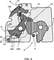
In der
Ist die Drehfalle
Dies wird allerdings in der Position Hauptrast der Drehfalle bei verschlossener Fahrzeugtür oder Fahrzeugklappe durch einen verschwenkbar angebrachten Blockadehebel
Im Fall der
Die Vorrast-Sperrklinke
Das Schloss gemäß der
Zur Erfindung gehört auch der Fall, dass die verschwenkbare Komponente, die in ihrer Endstellung nicht federbelastet ist, also im vorliegenden Fall die Hauptrast-Sperrklinke
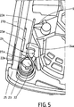
In der
In der
In der
Vorzugsweise ist die Hauptrast-Sperrklinke
Die
In der
Bezugszeichenliste LIST OF REFERENCE NUMBERS
- 11
- Wand einer Schlossplatte oder eines SchlosskastensWall of a lock plate or a lock case
- 22
- Einlaufschlitzinlet slot
- 33
- Schließbolzenlocking pin
- 44
- Drehfallecatch
- 55
- Befestigungsachsemounting axis
- 66
- Hauptrast-SperrklinkeMain position pawl
- 77
- Befestigungsachsemounting axis
- 88th
- Blockadehebelblocking lever
- 99
- Befestigungsachsemounting axis
- 1010
- Federfeather
- 10b10b
- Federarmspring arm
- 10b10b
- Federarmspring arm
- 1111
- Öffnungsrichtungopening direction
- 1212
- Anschlagattack
- 1313
- Vorrast-SperrklinkePosition pawl
- 1414
- Bolzenbolt
- 1616
- Drehrichtungdirection of rotation
- 1717
- Bolzenbolt
- 1818
- Bolzenbolt
- 1919
- Sperrfläche der Vorrast-SperrklinkeLocking surface of the pre-locking pawl
- 2121
- Hebelarm der Vorrast-SperrklinkeLever arm of the pre-locking pawl
- 2020
- Bolzenbolt
- 2222
- Dornmandrel
- 22a22a
- Nasenose
- 2323
- vorgespannte Federpreloaded spring
- 23a23a
- Federarmspring arm
- 23b23b
- Federarmspring arm
- 2424
- Anschlagattack
- 24a24a
- Auslegerboom
- 2525
- Schlossgehäuselock housing
- 25a25a
- Vorsprunghead Start
ZITATE ENTHALTEN IN DER BESCHREIBUNG QUOTES INCLUDE IN THE DESCRIPTION
Diese Liste der vom Anmelder aufgeführten Dokumente wurde automatisiert erzeugt und ist ausschließlich zur besseren Information des Lesers aufgenommen. Die Liste ist nicht Bestandteil der deutschen Patent- bzw. Gebrauchsmusteranmeldung. Das DPMA übernimmt keinerlei Haftung für etwaige Fehler oder Auslassungen.This list of the documents listed by the applicant has been generated automatically and is included solely for the better information of the reader. The list is not part of the German patent or utility model application. The DPMA assumes no liability for any errors or omissions.
Zitierte PatentliteraturCited patent literature
- DE 102007003948 A1 [0003, 0004, 0005, 0006, 0008] DE 102007003948 A1 [0003, 0004, 0005, 0006, 0008]
Claims (13)
Priority Applications (8)
| Application Number | Priority Date | Filing Date | Title |
|---|---|---|---|
| DE201120000341 DE202011000341U1 (en) | 2011-02-15 | 2011-02-15 | Lock for a flap or door |
| RU2013140478/12A RU2013140478A (en) | 2011-02-15 | 2012-01-19 | LOCK FOR FOLDING DOOR OR DOOR |
| CN201280017979.2A CN103477008B (en) | 2011-02-15 | 2012-01-19 | Lock for a flap or door |
| JP2013553787A JP5991995B2 (en) | 2011-02-15 | 2012-01-19 | Flap or door lock |
| KR1020137023572A KR101956938B1 (en) | 2011-02-15 | 2012-01-19 | Lock for a flap or door |
| EP12717148.6A EP2675975B1 (en) | 2011-02-15 | 2012-01-19 | Lock for a flap or door |
| US13/985,598 US9611677B2 (en) | 2011-02-15 | 2012-01-19 | Lock for a flap or door |
| PCT/DE2012/000047 WO2012110014A2 (en) | 2011-02-15 | 2012-01-19 | Lock for a flap or door |
Applications Claiming Priority (1)
| Application Number | Priority Date | Filing Date | Title |
|---|---|---|---|
| DE201120000341 DE202011000341U1 (en) | 2011-02-15 | 2011-02-15 | Lock for a flap or door |
Publications (1)
| Publication Number | Publication Date |
|---|---|
| DE202011000341U1 true DE202011000341U1 (en) | 2012-05-16 |
Family
ID=46017730
Family Applications (1)
| Application Number | Title | Priority Date | Filing Date |
|---|---|---|---|
| DE201120000341 Expired - Lifetime DE202011000341U1 (en) | 2011-02-15 | 2011-02-15 | Lock for a flap or door |
Country Status (8)
| Country | Link |
|---|---|
| US (1) | US9611677B2 (en) |
| EP (1) | EP2675975B1 (en) |
| JP (1) | JP5991995B2 (en) |
| KR (1) | KR101956938B1 (en) |
| CN (1) | CN103477008B (en) |
| DE (1) | DE202011000341U1 (en) |
| RU (1) | RU2013140478A (en) |
| WO (1) | WO2012110014A2 (en) |
Cited By (3)
| Publication number | Priority date | Publication date | Assignee | Title |
|---|---|---|---|---|
| DE102013012592A1 (en) * | 2013-07-30 | 2015-02-05 | Kiekert Aktiengesellschaft | Motor vehicle door lock |
| EP3321456A1 (en) * | 2016-11-10 | 2018-05-16 | Brose Schliesssysteme GmbH & Co. KG | Motor vehicle lock |
| CN110644865A (en) * | 2019-10-09 | 2020-01-03 | 上汽通用汽车有限公司 | Automobile door lock mechanism |
Families Citing this family (9)
| Publication number | Priority date | Publication date | Assignee | Title |
|---|---|---|---|---|
| DE102014201799A1 (en) * | 2014-01-31 | 2015-08-06 | Kiekert Ag | Closing device for a motor vehicle hood and method |
| JP6535919B2 (en) * | 2014-10-29 | 2019-07-03 | 三井金属アクト株式会社 | Vehicle door latch device and method of assembling vehicle door latch device |
| CN104763251B (en) * | 2015-03-26 | 2016-09-07 | 上海恩坦华汽车门系统有限公司 | Electronic promptly snap close based on lever principle |
| GB2594188B (en) * | 2016-04-08 | 2022-02-09 | Phillip Chevalier John | Latching systems for latching movable panels |
| JP7311449B2 (en) | 2017-03-24 | 2023-07-19 | 東芝ライフスタイル株式会社 | washing machine |
| CN107642284A (en) * | 2017-10-31 | 2018-01-30 | 无锡瑞林控制软件有限公司 | Automobile side door lock transmission device |
| DE102019134659A1 (en) | 2018-12-18 | 2020-06-18 | Magna Closures Inc. | INTELLIGENT LOCKING DEVICE WITH DOUBLE-LOCK LOCKING MECHANISM WITH FLEXIBLE CONNECTION TO A RELEASE MECHANISM |
| JP7215153B2 (en) * | 2018-12-26 | 2023-01-31 | 株式会社アイシン | Vehicle door lock device |
| JP7443951B2 (en) * | 2020-06-19 | 2024-03-06 | 三井金属アクト株式会社 | Vehicle door latch device |
Citations (1)
| Publication number | Priority date | Publication date | Assignee | Title |
|---|---|---|---|---|
| DE102007003948A1 (en) | 2006-11-22 | 2008-05-29 | Kiekert Ag | Locking unit with multipart pawl |
Family Cites Families (25)
| Publication number | Priority date | Publication date | Assignee | Title |
|---|---|---|---|---|
| US3334934A (en) * | 1965-08-09 | 1967-08-08 | Gen Motors Corp | Closure latch |
| DE2253954A1 (en) * | 1972-11-03 | 1974-05-16 | Kiekert Soehne Arn | MOTOR VEHICLE DOOR LOCK |
| JPS5532874B2 (en) | 1973-01-25 | 1980-08-27 | ||
| US4538845A (en) * | 1982-05-31 | 1985-09-03 | Mitsui Kinzoku Kogyo K. K. | Automobile locking apparatus |
| JPS6378977A (en) * | 1986-09-22 | 1988-04-09 | 株式会社 安成工業 | Body of door lock for car |
| CA1324726C (en) * | 1988-09-26 | 1993-11-30 | Yoshikazu Hamada | Noise suppressing device in lock device for vehicle |
| JPH0742818B2 (en) * | 1988-09-26 | 1995-05-10 | 三井金属鉱業株式会社 | Door opening noise prevention device for vehicle doors |
| US5181754A (en) * | 1990-07-20 | 1993-01-26 | Mitsui Kinzoku Kogyo Kabushiki Kaisha | Vehicular door lock device |
| US5328219A (en) * | 1992-12-24 | 1994-07-12 | General Motors Corporation | Vehicle closure latch |
| DE4306142C2 (en) * | 1993-02-27 | 1998-09-17 | Kiekert Ag | Motor vehicle door lock with a lock plate and with a lock housing with the housing base and end wall |
| JP3430436B2 (en) * | 1997-03-28 | 2003-07-28 | 株式会社大井製作所 | Door lock device for automobile |
| JP3143601B2 (en) * | 1997-05-16 | 2001-03-07 | 三井金属鉱業株式会社 | Device to prevent forgetting the key inside the vehicle |
| DE19725416C1 (en) * | 1997-06-17 | 1999-01-21 | Huf Huelsbeck & Fuerst Gmbh | Rotary latch lock, in particular for motor vehicles |
| GB2329928B (en) | 1997-10-06 | 2000-02-16 | Mitsui Mining & Smelting Co | Vehicle door latch device |
| GB0006931D0 (en) * | 2000-03-23 | 2000-05-10 | Meritor Light Vehicle Sys Ltd | Latch mechanism |
| US6581987B1 (en) * | 2000-11-15 | 2003-06-24 | Dura Global Technologies, Inc. | Hood latch mechanism with in-line striker spring |
| US7175211B2 (en) * | 2002-02-25 | 2007-02-13 | Intier Automotive Closures Inc. | Latch with shipping condition |
| ITTO20020511A1 (en) * | 2002-06-14 | 2003-12-15 | Intier Automotive Closures Spa | ASSEMBLY OF SUPPORT FOR A LOCK OF A VEHICLE AND METHOD OF REALIZATION OF SUCH ASSEMBLY |
| JP4230792B2 (en) * | 2003-02-14 | 2009-02-25 | シロキ工業株式会社 | Locking device |
| DE102004001988A1 (en) * | 2004-01-13 | 2005-08-04 | Kiekert Ag | Bearing mandrel for locking parts and motor vehicle door lock with a bearing mandrel |
| US20100127512A1 (en) * | 2008-11-26 | 2010-05-27 | Inteva Products Llp | Vehicle door latch |
| DE102009026452B4 (en) * | 2009-05-25 | 2019-05-23 | Kiekert Ag | Release lever with an opening moment for the rotary latch generating contour with multi-ratchet lock |
| DE102010003483B4 (en) * | 2009-06-12 | 2019-08-01 | Kiekert Ag | Lock with positive guide for pawl |
| US8235428B2 (en) | 2009-07-14 | 2012-08-07 | Kiekert Ag | Lock unit having a slotted pawl |
| CN201679327U (en) * | 2010-04-20 | 2010-12-22 | 无锡皓月汽车安全系统有限公司 | Mute car door lock |
-
2011
- 2011-02-15 DE DE201120000341 patent/DE202011000341U1/en not_active Expired - Lifetime
-
2012
- 2012-01-19 EP EP12717148.6A patent/EP2675975B1/en active Active
- 2012-01-19 KR KR1020137023572A patent/KR101956938B1/en active IP Right Grant
- 2012-01-19 JP JP2013553787A patent/JP5991995B2/en active Active
- 2012-01-19 RU RU2013140478/12A patent/RU2013140478A/en not_active Application Discontinuation
- 2012-01-19 CN CN201280017979.2A patent/CN103477008B/en active Active
- 2012-01-19 WO PCT/DE2012/000047 patent/WO2012110014A2/en active Application Filing
- 2012-01-19 US US13/985,598 patent/US9611677B2/en active Active
Patent Citations (1)
| Publication number | Priority date | Publication date | Assignee | Title |
|---|---|---|---|---|
| DE102007003948A1 (en) | 2006-11-22 | 2008-05-29 | Kiekert Ag | Locking unit with multipart pawl |
Cited By (4)
| Publication number | Priority date | Publication date | Assignee | Title |
|---|---|---|---|---|
| DE102013012592A1 (en) * | 2013-07-30 | 2015-02-05 | Kiekert Aktiengesellschaft | Motor vehicle door lock |
| EP3321456A1 (en) * | 2016-11-10 | 2018-05-16 | Brose Schliesssysteme GmbH & Co. KG | Motor vehicle lock |
| CN110644865A (en) * | 2019-10-09 | 2020-01-03 | 上汽通用汽车有限公司 | Automobile door lock mechanism |
| CN110644865B (en) * | 2019-10-09 | 2021-06-04 | 上汽通用汽车有限公司 | Automobile door lock mechanism |
Also Published As
| Publication number | Publication date |
|---|---|
| KR20140048852A (en) | 2014-04-24 |
| CN103477008B (en) | 2017-02-22 |
| US9611677B2 (en) | 2017-04-04 |
| EP2675975B1 (en) | 2015-03-11 |
| CN103477008A (en) | 2013-12-25 |
| WO2012110014A3 (en) | 2012-11-08 |
| JP5991995B2 (en) | 2016-09-14 |
| RU2013140478A (en) | 2015-03-27 |
| US20140217753A1 (en) | 2014-08-07 |
| EP2675975A2 (en) | 2013-12-25 |
| JP2014510205A (en) | 2014-04-24 |
| KR101956938B1 (en) | 2019-06-24 |
| WO2012110014A2 (en) | 2012-08-23 |
Similar Documents
| Publication | Publication Date | Title |
|---|---|---|
| EP2675975B1 (en) | Lock for a flap or door | |
| EP2553193B1 (en) | Motor vehicle lock | |
| DE102010003483B4 (en) | Lock with positive guide for pawl | |
| EP1617023B1 (en) | Lock on wings or doors of a vehicle | |
| EP2304139B1 (en) | Lock comprising a blocking lever in addition to a counterbalanced center of gravity | |
| EP2823120B1 (en) | Lock for a panel or door | |
| DE102009026921A1 (en) | Motor vehicle lock with closing aid | |
| DE102009029023A1 (en) | Lock for motor vehicle, has locking gear comprising rotary latch for retaining closing pin and ratchet pawl, where ratchet pawl is provided with rotatably mounted carrier handle and closing handle that is connected by joint | |
| EP2147178B1 (en) | Hinge arrangement | |
| DE102011004170B4 (en) | Lock for a flap or door | |
| DE102011076704A1 (en) | Lock for door or flap, is provided with locking mechanism of rotary latch and locking pawl for locking of rotary latch, where actuating lever is provided for opening of locking mechanism | |
| DE102008061524A1 (en) | Multi-way ratchet with locking hook | |
| DE102015122583A1 (en) | Safety device for a motor vehicle with a rotary latch and an ejection spring | |
| DE102012023261A1 (en) | Motor vehicle lock | |
| DE102009046880A1 (en) | Lock for locking door or flap of motor vehicle, has driving lever serving as locking lever for blocking locking gear during crash, acting together with spring, and rotating catch from preliminary locking position into main locking position | |
| DE102009026919A1 (en) | Lock for motor vehicle, has blocking lever blocking pawl when pawl locks rotary latch in closing position, where blocking lever moves pawl into locking position by pre-loading that is controlled by moving preliminary pawl | |
| DE102011003295A1 (en) | Motor vehicle lock | |
| DE102009026452B4 (en) | Release lever with an opening moment for the rotary latch generating contour with multi-ratchet lock | |
| DE102007012208A1 (en) | Device for locking a pivotable component of a motor vehicle | |
| DE102010030595A1 (en) | Lock for motor vehicle or building | |
| EP1959076B1 (en) | Automatic closing system for a door or window leaf | |
| EP3604722B1 (en) | Lock | |
| DE102013103479A1 (en) | Door Opener | |
| DE102011018848A1 (en) | Lock i.e. electrical lock, for locking e.g. closure element in motor car, has pivoted opening lever actuated for lifting ratchet pawl and coupled to or with ratchet pawl, where opening lever made of single piece of wire is curved | |
| DE102011051701A1 (en) | Locking device for cover of storage compartment e.g. glove compartment of motor vehicle, has operating element that is connected with locking bar and is displaceable in axial direction |
Legal Events
| Date | Code | Title | Description |
|---|---|---|---|
| R207 | Utility model specification |
Effective date: 20120705 |
|
| R079 | Amendment of ipc main class |
Free format text: PREVIOUS MAIN CLASS: E05B0065320000 Ipc: E05B0085260000 |
|
| R079 | Amendment of ipc main class |
Free format text: PREVIOUS MAIN CLASS: E05B0065320000 Ipc: E05B0085260000 Effective date: 20140120 |
|
| R150 | Utility model maintained after payment of first maintenance fee after three years | ||
| R150 | Utility model maintained after payment of first maintenance fee after three years |
Effective date: 20140310 |
|
| R151 | Utility model maintained after payment of second maintenance fee after six years | ||
| R152 | Utility model maintained after payment of third maintenance fee after eight years | ||
| R071 | Expiry of right | ||
| R082 | Change of representative |