DE112017002186B4 - HEAD-UP DISPLAY DEVICE - Google Patents
HEAD-UP DISPLAY DEVICE Download PDFInfo
- Publication number
- DE112017002186B4 DE112017002186B4 DE112017002186.3T DE112017002186T DE112017002186B4 DE 112017002186 B4 DE112017002186 B4 DE 112017002186B4 DE 112017002186 T DE112017002186 T DE 112017002186T DE 112017002186 B4 DE112017002186 B4 DE 112017002186B4
- Authority
- DE
- Germany
- Prior art keywords
- light
- reflection surface
- light guide
- image
- display
- Prior art date
- Legal status (The legal status is an assumption and is not a legal conclusion. Google has not performed a legal analysis and makes no representation as to the accuracy of the status listed.)
- Active
Links
- 230000003287 optical effect Effects 0.000 claims abstract description 59
- 230000015572 biosynthetic process Effects 0.000 claims abstract description 35
- 238000003384 imaging method Methods 0.000 claims abstract description 22
- 210000001747 pupil Anatomy 0.000 description 22
- 239000004973 liquid crystal related substance Substances 0.000 description 11
- 230000000052 comparative effect Effects 0.000 description 8
- 238000010586 diagram Methods 0.000 description 6
- 230000004048 modification Effects 0.000 description 6
- 238000012986 modification Methods 0.000 description 6
- 239000013256 coordination polymer Substances 0.000 description 4
- 239000011521 glass Substances 0.000 description 4
- 229920003002 synthetic resin Polymers 0.000 description 4
- 239000000057 synthetic resin Substances 0.000 description 4
- 238000002834 transmittance Methods 0.000 description 4
- 230000000694 effects Effects 0.000 description 3
- 230000001179 pupillary effect Effects 0.000 description 3
- 230000005540 biological transmission Effects 0.000 description 2
- 239000003086 colorant Substances 0.000 description 2
- 230000010287 polarization Effects 0.000 description 2
- OAICVXFJPJFONN-UHFFFAOYSA-N Phosphorus Chemical compound [P] OAICVXFJPJFONN-UHFFFAOYSA-N 0.000 description 1
- XAGFODPZIPBFFR-UHFFFAOYSA-N aluminium Chemical compound [Al] XAGFODPZIPBFFR-UHFFFAOYSA-N 0.000 description 1
- 229910052782 aluminium Inorganic materials 0.000 description 1
- 238000004040 coloring Methods 0.000 description 1
- 230000000593 degrading effect Effects 0.000 description 1
- 238000000151 deposition Methods 0.000 description 1
- 239000000446 fuel Substances 0.000 description 1
- 238000004519 manufacturing process Methods 0.000 description 1
- 239000000463 material Substances 0.000 description 1
- 239000011159 matrix material Substances 0.000 description 1
- 230000000149 penetrating effect Effects 0.000 description 1
- 230000000452 restraining effect Effects 0.000 description 1
- 239000010409 thin film Substances 0.000 description 1
- 230000000007 visual effect Effects 0.000 description 1
Images


Classifications
-
- G—PHYSICS
- G02—OPTICS
- G02B—OPTICAL ELEMENTS, SYSTEMS OR APPARATUS
- G02B27/00—Optical systems or apparatus not provided for by any of the groups G02B1/00 - G02B26/00, G02B30/00
- G02B27/01—Head-up displays
- G02B27/0179—Display position adjusting means not related to the information to be displayed
-
- G—PHYSICS
- G02—OPTICS
- G02B—OPTICAL ELEMENTS, SYSTEMS OR APPARATUS
- G02B27/00—Optical systems or apparatus not provided for by any of the groups G02B1/00 - G02B26/00, G02B30/00
- G02B27/01—Head-up displays
- G02B27/0101—Head-up displays characterised by optical features
-
- B—PERFORMING OPERATIONS; TRANSPORTING
- B60—VEHICLES IN GENERAL
- B60K—ARRANGEMENT OR MOUNTING OF PROPULSION UNITS OR OF TRANSMISSIONS IN VEHICLES; ARRANGEMENT OR MOUNTING OF PLURAL DIVERSE PRIME-MOVERS IN VEHICLES; AUXILIARY DRIVES FOR VEHICLES; INSTRUMENTATION OR DASHBOARDS FOR VEHICLES; ARRANGEMENTS IN CONNECTION WITH COOLING, AIR INTAKE, GAS EXHAUST OR FUEL SUPPLY OF PROPULSION UNITS IN VEHICLES
- B60K35/00—Instruments specially adapted for vehicles; Arrangement of instruments in or on vehicles
-
- G—PHYSICS
- G02—OPTICS
- G02B—OPTICAL ELEMENTS, SYSTEMS OR APPARATUS
- G02B27/00—Optical systems or apparatus not provided for by any of the groups G02B1/00 - G02B26/00, G02B30/00
- G02B27/01—Head-up displays
-
- B—PERFORMING OPERATIONS; TRANSPORTING
- B60—VEHICLES IN GENERAL
- B60K—ARRANGEMENT OR MOUNTING OF PROPULSION UNITS OR OF TRANSMISSIONS IN VEHICLES; ARRANGEMENT OR MOUNTING OF PLURAL DIVERSE PRIME-MOVERS IN VEHICLES; AUXILIARY DRIVES FOR VEHICLES; INSTRUMENTATION OR DASHBOARDS FOR VEHICLES; ARRANGEMENTS IN CONNECTION WITH COOLING, AIR INTAKE, GAS EXHAUST OR FUEL SUPPLY OF PROPULSION UNITS IN VEHICLES
- B60K2360/00—Indexing scheme associated with groups B60K35/00 or B60K37/00 relating to details of instruments or dashboards
- B60K2360/20—Optical features of instruments
- B60K2360/23—Optical features of instruments using reflectors
-
- B—PERFORMING OPERATIONS; TRANSPORTING
- B60—VEHICLES IN GENERAL
- B60K—ARRANGEMENT OR MOUNTING OF PROPULSION UNITS OR OF TRANSMISSIONS IN VEHICLES; ARRANGEMENT OR MOUNTING OF PLURAL DIVERSE PRIME-MOVERS IN VEHICLES; AUXILIARY DRIVES FOR VEHICLES; INSTRUMENTATION OR DASHBOARDS FOR VEHICLES; ARRANGEMENTS IN CONNECTION WITH COOLING, AIR INTAKE, GAS EXHAUST OR FUEL SUPPLY OF PROPULSION UNITS IN VEHICLES
- B60K2360/00—Indexing scheme associated with groups B60K35/00 or B60K37/00 relating to details of instruments or dashboards
- B60K2360/20—Optical features of instruments
- B60K2360/33—Illumination features
- B60K2360/334—Projection means
-
- G—PHYSICS
- G02—OPTICS
- G02B—OPTICAL ELEMENTS, SYSTEMS OR APPARATUS
- G02B27/00—Optical systems or apparatus not provided for by any of the groups G02B1/00 - G02B26/00, G02B30/00
- G02B27/01—Head-up displays
- G02B27/0101—Head-up displays characterised by optical features
- G02B2027/011—Head-up displays characterised by optical features comprising device for correcting geometrical aberrations, distortion
-
- G—PHYSICS
- G02—OPTICS
- G02B—OPTICAL ELEMENTS, SYSTEMS OR APPARATUS
- G02B27/00—Optical systems or apparatus not provided for by any of the groups G02B1/00 - G02B26/00, G02B30/00
- G02B27/01—Head-up displays
- G02B27/0101—Head-up displays characterised by optical features
- G02B2027/013—Head-up displays characterised by optical features comprising a combiner of particular shape, e.g. curvature
-
- G—PHYSICS
- G02—OPTICS
- G02B—OPTICAL ELEMENTS, SYSTEMS OR APPARATUS
- G02B27/00—Optical systems or apparatus not provided for by any of the groups G02B1/00 - G02B26/00, G02B30/00
- G02B27/01—Head-up displays
- G02B27/0179—Display position adjusting means not related to the information to be displayed
- G02B2027/0183—Adaptation to parameters characterising the motion of the vehicle
Landscapes
- Physics & Mathematics (AREA)
- Engineering & Computer Science (AREA)
- General Physics & Mathematics (AREA)
- Optics & Photonics (AREA)
- Chemical & Material Sciences (AREA)
- Combustion & Propulsion (AREA)
- Transportation (AREA)
- Mechanical Engineering (AREA)
- Instrument Panels (AREA)
Abstract
Head-up-Display-Vorrichtung, die dazu ausgelegt ist, Displaylicht, das an einer konkaven Bilderzeugungsreflexionsoberfläche (42) zu reflektieren ist, auf einen die konkave Bilderzeugungsreflexionsoberfläche (42) aufweisenden Kombinator (40) zu projizieren und ein virtuelles Bild (VI) anzuzeigen, das für einen Insassen sichtbar ist, wobei der Kombinator (40) an einer Instrumententafel (2) eines Fahrzeugs (1) befestigt und oberhalb eines oberen Oberflächenabschnitts (2a) der Instrumententafel angeordnet wird, wobei die Head-up-Display-Vorrichtung aufweist:- einen Projektor (10), der dazu ausgelegt ist, das Displaylicht in Form eines Lichtstrahls zu projizieren; und- einen Lichtleitspiegel (30) mit einer Lichtleitreflexionsoberfläche (32), die dazu ausgelegt ist, das Displaylicht von dem Projektor (10) in Richtung der Bilderzeugungsreflexionsoberfläche (42) zu reflektieren, wobei- die Lichtleitreflexionsoberfläche (32) konvex ist, und- der Projektor (10) aufweist:- eine Lichtquelleneinheit (12), die dazu ausgelegt ist, Licht zu emittieren; und- einen optischen Öffnungsabschnitt (20), der optisch offen und dazu ausgelegt ist, das von der Lichtquelleneinheit (12) emittierte Licht durch die Öffnung laufen zu lassen, um ein Bild zu erzeugen, und das Bild als das Displaylicht zu projizieren, wobei- eine Brechkraft der Lichtleitreflexionsoberfläche (32) als ϕ1 definiert ist,- eine Brechkraft der Bilderzeugungsreflexionsoberfläche (42) als ϕ2 definiert ist,- ein Abstand zwischen der Bilderzeugungsreflexionsoberfläche (42) und der Lichtleitreflexionsoberfläche (32) als L3 definiert ist,- ein Abstand zwischen einem konjugierten Punkt (CP), der optisch mit der Lichtquelleneinheit (12) konjugiert ist, und dem virtuellen Bild, das von dem konjugierten Punkt visuell erkannt wird, als Id definiert ist, was einem Wert von kleiner als null entspricht,- ein Lichtstrahlradius des Displaylichts an dem konjugierten Punkt als Es definiert ist,- ein Abstand zwischen dem konjugierten Punkt (CP) und der Bilderzeugungsreflexionsoberfläche (42) als Ed definiert ist,- -Es/Id als A definiert ist und Es+Ed-(Es/Id) als B definiert ist,- sich der folgende Ausdruck ergibt:B−L3⋅(A+B⋅ϕ2)(A+B⋅ϕ2)+{B−L3⋅(A+B⋅ϕ2)}⋅ϕ1>0- ein Abstand zwischen der Lichtleitreflexionsoberfläche (32) und dem optischen Öffnungsabschnitt als L4 definiert ist,- ein halber Bildwinkel des virtuellen Bildes als θ definiert ist,- θ als C definiert ist,- -Ed-θ als D definiert ist, und- sich der folgende Ausdruck ergibt:D−(C+D⋅ϕ2)⋅L3−L4⋅[(C+D⋅ϕ2)+{D−(C+D⋅ϕ2)⋅L3}⋅ϕ1](C+D⋅ϕ2)+{D−(C+D⋅ϕ2)⋅L3}⋅ϕ1<0A head-up display device configured to project display light to be reflected on a concave image-forming reflection surface (42) onto a combiner (40) having the concave image-forming reflection surface (42) and display a virtual image (VI). Visible to an occupant, the combiner (40) being attached to an instrument panel (2) of a vehicle (1) and being positioned above an upper surface portion (2a) of the instrument panel, the head-up display device comprising: - a projector (10) adapted to project the display light in the form of a light beam; and- a light guide mirror (30) having a light guide reflective surface (32) adapted to reflect the display light from the projector (10) toward the imaging reflective surface (42), wherein- the light guide reflective surface (32) is convex, and- the The projector (10) comprises: - a light source unit (12) adapted to emit light; and- an optical aperture portion (20) which is optically open and adapted to pass the light emitted from the light source unit (12) through the aperture to form an image and to project the image as the display light, wherein- a refractive power of the light guide reflection surface (32) is defined as φ1, - a refractive power of the image formation reflection surface (42) is defined as φ2, - a distance between the image formation reflection surface (42) and the light guide reflection surface (32) is defined as L3, - a distance between a conjugate point (CP) optically conjugated with the light source unit (12) and the virtual image visually recognized from the conjugate point is defined as Id which corresponds to a value less than zero,- a light beam radius of the display light at the conjugate point is defined as Es,- a distance between the conjugate point (CP) and the imaging reflection surface (42) a ls Ed is defined,- -Es/Id is defined as A and Es+Ed-(Es/Id) is defined as B,- the following expression results:B−L3⋅(A+B⋅ϕ2)(A+ B⋅ϕ2)+{B−L3⋅(A+B⋅ϕ2)}⋅ϕ1>0- a distance between the light guide reflecting surface (32) and the optical opening portion is defined as L4,- a half angle of view of the virtual image is defined as θ is,- θ is defined as C,- -Ed-θ is defined as D, and- the following expression results:D−(C+D⋅ϕ2)⋅L3−L4⋅[(C+D⋅ϕ2)+ {D−(C+D⋅ϕ2)⋅L3}⋅ϕ1](C+D⋅ϕ2)+{D−(C+D⋅ϕ2)⋅L3}⋅ϕ1<0
Description
QUERVERWEIS AUF VERWANDTE ANMELDUNGCROSS REFERENCE TO RELATED APPLICATION
Diese Anmeldung basiert auf der am 26. April 2016 eingereichten japanischen Patentanmeldung Nr.
GEBIET DER ERFINDUNGFIELD OF THE INVENTION
Die vorliegende Erfindung betrifft eine Head-up-Display-Vorrichtung, die dazu ausgelegt ist, ein virtuelles Bild anzuzeigen, das für einen Insassen erkennbar ist.The present invention relates to a head-up display device configured to display a virtual image recognizable to an occupant.
BISHERIGER STAND DER TECHNIKPREVIOUS STATE OF THE TECHNOLOGY
Bekannt ist eine Head-up-Display-Vorrichtung (nachstehend als HUD-Vorrichtung abgekürzt), die dazu ausgelegt ist, ein virtuelles Bild anzuzeigen, das für einen Insassen erkennbar ist. Eine HUD-Vorrichtung, die aus dem nachfolgend aufgeführten Patentdokument 1 bekannt ist, weist einen Projektor, einen Lichtleitspiegel und einen Kombinator mit einer Bilderzeugungsreflexionsoberfläche auf. Der Projektor projiziert ein Displaylicht in Form eines Lichtstrahls. Der Lichtleitspiegel weist eine planare Lichtleitreflexionsoberfläche auf, die das Displaylicht von dem Projektor in Richtung der Bilderzeugungsreflexionsoberfläche reflektiert. Die Bilderzeugungsreflexionsoberfläche des Kombinators reflektiert das Displaylicht von dem Lichtleitspiegel.There is known a head-up display (hereinafter abbreviated as HUD) device configured to display a virtual image recognizable to an occupant. A HUD device known from
Wenn die vorstehend beschriebene HUD-Vorrichtung an einer Instrumententafel eines Fahrzeugs befestigt ist, ist die Bilderzeugungsreflexionsoberfläche des Kombinators vorzugsweise oberhalb eines oberen Oberflächenabschnitts der Instrumententafel angeordnet, in Anbetracht der Sichtbarkeit (wie beispielsweise der Bewegung einer Sichtlinie) des virtuellen Bildes.When the HUD device described above is mounted on an instrument panel of a vehicle, the image formation reflection surface of the combiner is preferably located above an upper surface portion of the instrument panel in consideration of visibility (such as movement of a line of sight) of the virtual image.
Ferner würde, wenn ein Reflexionswinkel des Displaylichts an der Bilderzeugungsreflexionsoberfläche des Kombinators zunimmt, das virtuelle Bild beispielsweise asymmetrisch vertikal verzerrt werden. Aus diesem Grund ist es denkbar, eine Zunahme im Reflexionswinkel des Displaylichts an der Bilderzeugungsreflexionsoberfläche zu mindern.Further, when a reflection angle of the display light at the image formation reflection surface of the combiner increases, the virtual image would be asymmetrically vertically distorted, for example. For this reason, it is conceivable to restrain an increase in the reflection angle of the display light on the image formation reflection surface.
Bei der Bilderzeugungsreflexionsoberfläche des großen Lichtleitspiegels gemäß Patentdokument 1 würde es jedoch, da der Anordnungsfreiheitsgrad gering ist, schwierig werden, das Displaylicht in Richtung der oberhalb des oberen Oberflächenabschnitts angeordneten Bilderzeugungsreflexionsoberfläche zu reflektieren und gleichzeitig eine Zunahme im Reflexionswinkel zu mindern.However, in the image formation reflection surface of the large light guide mirror according to
LITERATUR AUS DEM STAND DER TECHNIKPRIOR ART LITERATURE
PATENTLITERATURPATENT LITERATURE
Patentdokument 1:
KURZDARSTELLUNG DER ERFINDUNGSUMMARY OF THE INVENTION
Es ist Aufgabe der vorliegenden Erfindung, eine HUD-Vorrichtung mit einer hohen Sichtbarkeit eines virtuellen Bildes bereitzustellen.It is an object of the present invention to provide a HUD device with high visibility of a virtual image.
Bei der Bilderzeugungsreflexionsoberfläche des großen Lichtleitspiegels gemäß Patentdokument 1 würde es, wie vorstehend beschrieben, da der Anordnungsfreiheitsgrad gering ist, schwierig sein, das Displaylicht in Richtung der oberhalb des oberen Oberflächenabschnitts angeordneten Bilderzeugungsreflexionsoberfläche zu reflektieren und gleichzeitig eine Zunahme im Reflexionswinkel zu mindern. Folglich haben die Erfinder der vorliegenden Erfindung eine Verringerung in der Größe des Lichtleitspiegels untersucht.In the image-forming reflection surface of the large light guide mirror according to
Insbesondere haben die Erfinder der vorliegenden Erfindung berücksichtigt, dass dann, wenn die Bilderzeugungsreflexionsoberfläche des Kombinators konkav ist und ein Krümmungsradius der konkaven Oberfläche verringert wird, die Größe des Lichtleitspiegels verringert werden kann, da ein Lichtstrahl des Displaylichts, der auf die Bilderzeugungsreflexionsoberfläche fällt, verkleinert werden kann. Wenn jedoch der Lichtleitspiegel mit einer planaren Lichtleitreflexionsoberfläche gemäß Patentdokument 1 eingesetzt wird, muss der Projektor beispielsweise in der Nähe des Lichtleitspiegels angeordnet werden. Wenn der Projektor in der Nähe des Lichtleitspiegels installiert wird, bestehen beispielsweise dahingehend Bedenken, dass der Lichtstrahl, der an der Lichtleitreflexionsoberfläche reflektiert worden ist, den Projektor beeinträchtigt oder dergleichen, wodurch die Sichtbarkeit des virtuellen Bildes beeinträchtigt wird.In particular, the inventors of the present invention considered that when the image formation reflection surface of the combiner is concave and a radius of curvature of the concave surface is reduced, the size of the light guide mirror can be reduced since a light beam of the display light incident on the image formation reflection surface is reduced can. However, if the For example, when the light guide mirror having a planar light guide reflecting surface according to
Gemäß einem Aspekt der vorliegenden Erfindung wird eine Head-up-Display-Vorrichtung bereitgestellt, die dazu ausgelegt ist, Displaylicht, das an einer konkaven Bilderzeugungsreflexionsoberfläche zu reflektieren ist, auf einen Kombinator mit der konkaven Bilderzeugungsreflexionsoberfläche zu projizieren und ein virtuelles Bild anzuzeigen, das für einen Insassen sichtbar ist. Der Kombinator wird an einer Instrumententafel eines Fahrzeugs befestigt und oberhalb eines oberen Oberflächenabschnitts der Instrumententafel angeordnet. Die Head-up-Display-Vorrichtung weist einen Projektor auf, der dazu ausgelegt ist, das Displaylicht in Form eines Lichtstrahls zu projizieren. Die Head-up-Display-Vorrichtung weist ferner einen Lichtleitspiegel mit einer Lichtleitreflexionsoberfläche auf, die dazu ausgelegt ist, das Displaylicht von dem Projektor in Richtung der Bilderzeugungsreflexionsoberfläche zu reflektieren. Die Lichtleitreflexionsoberfläche ist konvex.According to one aspect of the present invention, a head-up display device is provided, which is designed to display light to be reflected on a concave image-forming reflection surface, to project onto a combiner with the concave image-forming reflection surface and display a virtual image that is for an occupant is visible. The combiner is attached to an instrument panel of a vehicle and positioned above an upper surface portion of the instrument panel. The head-up display device has a projector configured to project the display light in the form of a light beam. The head-up display device further includes a light guide mirror having a light guide reflection surface configured to reflect the display light from the projector toward the image formation reflection surface. The light guide reflection surface is convex.
Figurenlistecharacter list
Die obigen und weitere Aufgaben, Eigenschaften und Vorteile der vorliegenden Erfindung sind aus der nachfolgenden detaillierten Beschreibung unter Bezugnahme auf die beigefügten Zeichnungen näher ersichtlich. In den Zeichnungen zeigt:
-
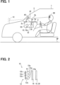
1 eine schematische Abbildung zur Veranschaulichung eines eingebauten Zustands einer HUD-Vorrichtung in einem Fahrzeug gemäß einer Ausführungsform; -
2 eine schematische Abbildung zur Veranschaulichung einer Konfiguration eines Projektors gemäß der Ausführungsform; -
3 eine schematische Abbildung eines optischen Öffnungsabschnitts, in einer Normalen-Richtung des optischen Öffnungsabschnitts betrachtet, gemäß der Ausführungsform; -
4 eine vergrößerte Ansicht zur Veranschaulichung eines Abschnitts VI in der3 ; -
5 eine schematische Abbildung zur Veranschaulichung eines optischen Systems durch die HUD-Vorrichtung gemäß der Ausführungsform; -
6 eine schematische Abbildung zur Veranschaulichung eines optischen Systems durch eine HUD-Vorrichtung gemäß einem Vergleichsbeispiel; und -
7 eine schematische Abbildung zur Veranschaulichung eines optischen Systems durch eine HUD-Vorrichtung gemäß einem Referenzbeispiel.
-
1 12 is a schematic diagram showing an installed state of a HUD device in a vehicle according to an embodiment; -
2 12 is a schematic diagram showing a configuration of a projector according to the embodiment; -
3 12 is a schematic diagram of an optical opening portion viewed in a normal direction of the optical opening portion according to the embodiment; -
4 an enlarged view illustrating a section VI in the3 ; -
5 12 is a schematic diagram showing an optical system by the HUD device according to the embodiment; -
6 12 is a schematic diagram showing an optical system by a HUD device according to a comparative example; and -
7 12 is a schematic diagram showing an optical system by a HUD device according to a reference example.
BESCHREIBUNG VON AUSFÜHRUNGSFORMENDESCRIPTION OF EMBODIMENTS
Nachstehend ist eine Ausführungsform der vorliegenden Erfindung unter Bezugnahme auf die Zeichnungen beschrieben.An embodiment of the present invention will be described below with reference to the drawings.
Wie in
Der sichtbare Bereich EB ist ein Raumbereich, in dem das virtuelle Bild VI, das von der HUD-Vorrichtung 100 angezeigt wird, sichtbar ist. Genauer gesagt, wenn sich die Augen des Insassen innerhalb des sichtbaren Bereichs EB befinden, ist das virtuelle Bild VI visuell erkennbar, und wenn die Augen des Insassen den sichtbaren Bereich EB verlassen, wird die Sichtbarkeit des virtuellen Bildes VI, verglichen mit ersterem Fall, beeinträchtigt, d.h. ist es schwieriger, das virtuelle Bild VI zu erkennen.The visible area EB is a spatial area where the virtual image VI displayed by the
In der nahfolgenden Beschreibung der vorliegenden Ausführungsform ist die Signifikanz von aufwärts oder abwärts, die ein Positionsverhältnis beschreiben, festgelegt, indem Höhen von einer horizontalen Ebene HP miteinander verglichen sind, wenn sich das Fahrzeug 1 auf der horizontalen Ebene HP befindet.In the following description of the present embodiment, the significance of upward or downward describing a positional relationship is determined by comparing heights from a horizontal plane HP with each other when the
Nachstehend ist eine bestimmte Konfiguration der obigen HUD-Vorrichtung 100 beschrieben. Die HUD-Vorrichtung 100 weist einen Projektor 10, einen Lichtleitspiegel 30 und einen Kombinator 40 auf. Von diesen Komponenten sind der Projektor 10 und der Lichtleitspiegel 30 in einem Gehäuse 50 der HUD-Vorrichtung 100 untergebracht.A specific configuration of the
Wie in
Die Lichtquelleneinheit 12 weist mehrere lichtemittierende Vorrichtungen 12a (z.B. drei) auf, wie beispielsweise LED-(Leuchtdiode)-Vorrichtungen. Die mehreren lichtemittierenden Vorrichtungen 12a sind auf einer Lichtquellenleiterplatte 12b angeordnet und über ein Verdrahtungsmuster auf der Lichtquellenleiterplatte 12b mit einer Energieversorgung verbunden. Jede der lichtemittierenden Vorrichtungen 12a emittiert ein Licht mit einer Lichtemissionsmenge entsprechend einem Strombetrag durch Bestromung. Genauer gesagt, in jeder der lichtemittierenden Vorrichtungen 12a ist beispielsweise eine blaue Diode mit Phosphor bedeckt, um so eine pseudoweiße Lichtemission zu realisieren.The
Die Kondensoreinheit 14 ist zwischen der Lichtquelleneinheit 12 und dem optischen Öffnungsabschnitt 20 angeordnet und weist eine Kondensorlinse 15 und eine Feldlinse 16 auf. Die Kondensorlinse 15 ist zwischen der Lichtquelleneinheit 12 und der Feldlinse 16 angeordnet und aus Kunstharz, Glas oder dergleichen aufgebaut, um eine Lichttransmissionseigenschaft aufzuweisen. Insbesondere ist die Kondensorlinse 15 der vorliegenden Ausführungsform ein Linsenarray, in dem mehrere konvexe Linsenelemente 15a in Übereinstimmung mit der Anzahl und Anordnung der lichtemittierenden Vorrichtungen 12a als Array angeordnet sind. Die Kondensorlinse 15 verdichtet das von der Seite der Lichtquelleneinheit 12 einfallende Licht und emittiert das verdichtete Licht zur Seite der Feldlinse 16.The condenser unit 14 is arranged between the
Die Feldlinse 16 ist zwischen der Kondensorlinse 15 und dem optischen Öffnungsabschnitt 20 angeordnet und aus Kunstharz, Glas oder dergleichen aufgebaut, um eine Lichttransmissionseigenschaft aufzuweisen. Insbesondere ist die Feldlinse 16 der vorliegenden Ausführungsform eine Fresnel-Linse, die in Form einer Platte ausgebildet ist. Die Feldlinse 16 verdichtet das von der Seite der Kondensorlinse 15 einfallende Licht weiter und emittiert das verdichtete Licht zur Seite des optischen Öffnungsabschnitts 20.The field lens 16 is arranged between the
Es sollte beachtet werden, dass andere Konfigurationen anwendbar sind, solange die Kondensoreinheit bzw. lichtverdichtende Einheit 14 das von der Lichtquelleneinheit 12 emittierte Licht verdichtet. Die Kondensoreinheit 14 kann beispielsweise durch eine Linse oder einen Spiegel aufgebaut sein und kann aufgebaut werden, indem eine Linse, ein Spiegel, eine Streuscheibe oder andere optische Elemente zu der vorstehend beschriebenen Konfiguration hinzugefügt werden.It should be noted that other configurations are applicable as long as the condensing unit 14 condenses the light emitted from the
Der optische Öffnungsabschnitt 20 ist optisch offen, um zu bewirken, dass ein Teil des von der Lichtquelleneinheit 12 emittierten Lichts den optischen Öffnungsabschnitt 20 durchläuft, um ein Bild zu bilden, und projiziert das Bild als das Displaylicht in Richtung des Lichtleitspiegels 30 auf einer Seite gegenüberliegend zu der Lichtquelleneinheit 12 und der Kondensoreinheit 14.The
Genauer gesagt, der optische Öffnungsabschnitt 20 der vorliegenden Ausführungsform ist aus einer durchlässigen Aktivmatrix-Flüssigkristalltafel 19 unter Verwendung eines Dünnschichttransistors (TFT) aufgebaut. In dem optischen Öffnungsabschnitt 20, der vorstehend beschrieben ist, sind, wie in den
Ferner weist, wie in der
In einem Abschnitt, der den Öffnungsbereich 22a des optischen Öffnungsabschnitts 20 beinhaltet, sind ein Paar von Polarisierungsplatten, eine Flüssigkristallschicht, die zwischen dem Paar von Polarisierungsplatten angeordnet ist, und dergleichen übereinandergeschichtet angeordnet. Jede der Polarisierungsplatten weist eine Eigenschaft zum Durchlassen des Lichts, das in einer vorbestimmten Richtung polarisiert ist, und zum Absorbieren des Lichts, das in einer Richtung im Wesentlichen senkrecht zu der vorbestimmten Richtung polarisiert ist, auf. Das Paar von Polarisierungsplatten ist in den jeweiligen vorbestimmten Richtungen im Wesentlichen orthogonal zueinander angeordnet. Die Flüssigkristallschicht kann eine Polarisationsrichtung des auf die Flüssigkristallschicht fallenden Lichts in Übereinstimmung mit einer angelegten Spannung durch Anlegen der Spannung für jedes Flüssigkristallpixel drehen. Ein Anteil des Lichts, das die hintere Polarisationsplatte aufgrund der Drehung der Polarisationsrichtung durchläuft, d.h. eine Lichtdurchlässigkeit oder Transmittanz, kann geändert werden.In a portion including the
Das von der Seite der Kondensoreinheit 14 auf das Array der Flüssigkristallpixel 22 in dem optischen Öffnungsabschnitt 20 fallende Licht wird in der Transmittanz des Lichts für jedes der Flüssigkristallpixel 22 gesteuert, wodurch ein Bild erzeugt wird. Farbfilter wechselseitig verschiedener Farben (wie beispielsweise rot, grün und blau) sind in den benachbarten Flüssigkristallpixeln 22 vorgesehen, und es werden verschiedene Farben durch eine Kombination dieser Farbfilter reproduziert.The light incident on the array of
Auf diese Weise projiziert der Projektor 10 das Displaylicht in Form eines Lichtstrahls durch den optischen Öffnungsabschnitt 20. Das durch den Projektor 10 projizierte Displaylicht fällt „gezielt“ auf den Lichtleitspiegel 30.In this way, the
Wie in
Der Kombinator 40 ist aus Kunstharz, Glas oder dergleichen aufgebaut und beispielsweise in Form einer lichtdurchlässigen Platte ausgebildet, die sich aus dem Gehäuse 50 heraus aufwärts erstreckt. Der Kombinator 40 weist eine Bilderzeugungsreflexionsoberfläche 42 auf, die sich oberhalb des oberen Oberflächenabschnitts 2a und an einer Oberfläche auf einer Seite, die dem Lichtleitspiegel 30 und dem sichtbaren Bereich EB zugewandt ist, befindet. Die Bilderzeugungsreflexionsoberfläche 42 ist in einer konkaven Form gekrümmt, um eine glatte, konkave Oberflächenform bereitzustellen. Das von der Lichtleitreflexionsoberfläche 32 einfallende Displaylicht wird durch die Bilderzeugungsreflexionsoberfläche 42 in Richtung des sichtbaren Bereichs EB reflektiert. Der Insasse kann das virtuelle Bild VI durch das Displaylicht des Bildes, das den sichtbaren Bereich EB auf diese Weise erreicht hat, visuell erkennen.The
In diesem Beispiel ist der Kombinator 40 näher als die Windschutzscheibe 3 zu dem sichtbaren Bereich EB angeordnet. Folglich kann der Insasse eine Szenerie außerhalb des Fahrzeugs, die eine Straße, Verkehrszeichen und dergleichen umfasst, durch den lichtdurchlässigen Kombinator 40 und die Windschutzscheibe 3 visuell erkennen. Genauer gesagt, das virtuelle Bild VI, das visuell zu erkennen ist, wird der Szenerie außerhalb des Fahrzeugs überlagert angezeigt.In this example, the
Das optische System, das durch die HUD-Vorrichtung 100 gebildet wird, die die vorstehend beschriebene überlagerte Anzeige ausführen kann, ist nachstehend unter Bezugnahme auf die
Nachstehend ist, in dem Strahlengang des optischen Systems gemäß
Ferner ist eine Strahlungsleistung der Lichtleitreflexionsoberfläche 32 als ϕ1 definiert (ϕ1<0) und eine Strahlungsleistung der Bilderzeugungsreflexionsoberfläche 42 als ϕ2 definiert (ϕ2>0). Eine Brennweite der Lichtleitreflexionsoberfläche 32 ist als f1 = 1/ϕ1 definiert, und eine Brennweite der Bilderzeugungsreflexionsoberfläche 42 ist als f2 = 1/ϕ2 definiert. Es wird angenommen, dass eine kombinierte Brennweite der Bilderzeugungsreflexionsoberfläche 42 und der Lichtleitreflexionsoberfläche 32 positiv ist.Further, a radiant power of the light
Ferner ist ein Halbwert der Größe des virtuellen Bildes VI als Is definiert, ein Halbwert der Größe des sichtbaren Bereichs EB als Es definiert und ein Halbwert der Größe des optischen Öffnungsabschnitts 20 als Os definiert (Os<0), vorausgesetzt, dass ein an der optischen Öffnung 20 erzeugtes Bild ein reelles Bild ist.Further, a half value of the size of the virtual image VI is defined as Is, a half value of the size of the visible area EB is defined as Es, and a half value of the size of the
In der vorliegenden Ausführungsform sind die Lichtquelleneinheit 12 und der sichtbare Bereich EB im Wesentlichen zueinander optisch konjugiert. Bei jedem Parameter kann der sichtbare Bereich EB durch einen konjugierten Punkt CP ersetzt werden, der optisch mit der Lichtquelleneinheit 12 konjugiert ist. Der Abstand Id kann beispielsweise als ein Abstand zwischen dem konjugierten Punkt CP und dem virtuellen Bild VI verstanden werden, und der Halbwert Es der Größe des sichtbaren Bereichs EB kann als ein Lichtstrahlradius des Displaylichts an dem konjugierten Punkt CP (insbesondere des gesamten Displaylichts, das von dem Projektor 10 projiziert wird) verstanden werden.In the present embodiment, the
In dem optischen System, das vorstehend beschrieben ist, werden ein Winkel eines paraxialen Bildlichtstrahls IMR und eine Höhe des paraxialen Bildlichtstrahls IMR der Reihe nach durch eine Rückstrahlverfolgung (Back-Ray-Tracing) von dem sichtbaren Bereich EB zu der Seite des optischen Öffnungsabschnitts 20 erhalten. In diesem Beispiel beschreibt der Winkel des paraxialen Bildlichtstrahls IMR einen Winkel, in dem sich ein Lichtstrahl (nachstehend als paraxialer Bildlichtstrahl IMR bezeichnet) in einer Richtung, die ein Ende des sichtbaren Bereichs EB und eine Mitte des virtuellen Bildes VI zwischen dem sichtbaren Bereich EB und der Bilderzeugungsreflexionsoberfläche 42 verbindet, bezüglich eines Lichtstrahls (nachstehend als Hauptlichtstrahl PRR bezeichnet) erstreckt, der durch eine Mitte (wie beispielsweise den konjugierten Punkt CP) des sichtbaren Bereichs EB und eine Mitte des optischen Öffnungsabschnitts 20 führt. Nachstehend ist der Winkel des paraxialen Bildlichtstrahls IMR in Radiant beschrieben. Die Höhe des paraxialen Bildlichtstrahls IMR ist ein Abstand zwischen dem Hauptlichtstrahl PRR und dem paraxialer Bildlichtstrahl IMR in der Richtung senkrecht zum Hauptlichtstrahl PRR.In the optical system described above, an angle of a paraxial image light beam IMR and a height of the paraxial image light beam IMR are obtained in order by back ray tracing from the visible area EB to the
Der Winkel des paraxialen Bildlichtstrahls IMR ist gleich -Es/Id zwischen dem sichtbaren Bereich EB und der Bilderzeugungsreflexionsoberfläche 42, was als HUD-Konstante A festgelegt wird. Auf der Bilderzeugungsreflexionsoberfläche 42 ist die Höhe des paraxialen Bildlichtstrahls IMR gleich Es+Ed-(Es/Id), was als HUD-Konstante B festgelegt wird. Der Winkel des paraxialen Bildlichtstrahls IMR ist gleich A+B-ϕ2 zwischen der Bilderzeugungsreflexionsoberfläche 42 und der Lichtleitreflexionsoberfläche 32. Auf der Lichtleitreflexionsoberfläche 32 ist die Höhe des paraxialen Bildlichtstrahls IMR gleich B-L3-(A+B-ϕ2). Der Winkel des paraxialen Bildlichtstrahls IMR ist gleich (A+B-ϕ2)+(B-L3-(A+B-ϕ2))-ϕ1 zwischen der Lichtleitreflexionsoberfläche 32 und dem optischen Öffnungsabschnitt 20.The angle of the paraxial image light beam IMR is equal to -Es/Id between the visible area EB and the
In dem optischen Öffnungsabschnitt 20 kann, da die Höhe des paraxialen Bildlichtstrahls IMR gleich 0 ist, der Abstand L4 durch eine Gleichung gemäß dem nachfolgenden Ausdruck 1 beschrieben werden.In the
![]()
![]()
Da sich der optische Öffnungsabschnitt 20 in dem Strahlengang nicht zwischen der Lichtleitreflexionsoberfläche 32 und der Bilderzeugungsreflexionsoberfläche 42 befinden sollte, muss die Bedingung L4>0 erfüllt sein. Folglich wird die Bedingung gemäß dem nachfolgenden Ausdruck 2 hergeleitet.Since the
![]()
![]()
Anschließend werden ein Winkel eines paraxialen Pupillenlichtstrahls PUR und eine Höhe des paraxialen Pupillenlichtstrahls PUR der Reihe nach durch Rückstrahlverfolgung von dem sichtbaren Bereich EB zu der Seite des optischen Öffnungsabschnitts 20 erhalten. In diesem Beispiel ist der Winkel des paraxialen Pupillenlichtstrahls PUR ein Winkel, in dem sich ein Lichtstrahl (nachstehend als paraxialer Pupillenlichtstrahl PUR bezeichnet) in einer Richtung, die eine Mitte des sichtbaren Bereichs EB und einen Endabschnitt des virtuellen Bildes VI zwischen dem Sichtbereich EB und der Bilderzeugungsreflexionsoberfläche 42 verbindet, bezüglich des Hauptlichtstrahls PRR erstreckt. Die Höhe des paraxialen Pupillenlichtstrahls PUR ist ein Abstand zwischen dem Hauptlichtstrahl PRR und dem paraxialen Pupillenlichtstrahl PUR in einer Richtung senkrecht zu dem Hauptlichtstrahl PRR.Then, an angle of a paraxial pupil light beam PUR and a height of the paraxial pupil light beam PUR are obtained in order by retroreflective tracing from the visible area EB to the
Der Winkel des paraxialen Pupillenlichtstrahls PUR entspricht einem halben Bildwinkel θ des virtuellen Bildes VI zwischen dem sichtbaren Bereich EB und der Bilderzeugungsreflexionsoberfläche 42 und ist θ=-Is/Id, was als HUD-Konstante C festgelegt wird. Auf der Bilderzeugungsreflexionsoberfläche 42 ist die Höhe des paraxialen Pupillenlichtstrahls PUR gleich -Ed-θ, was als HUD-Konstante D festgelegt wird. Der Winkel des paraxialen Pupillenlichtstrahls PUR ist gleich C+D-ϕ2 zwischen der Bilderzeugungsreflexionsoberfläche 42 und der Lichtleitreflexionsoberfläche 32. In der Lichtleitreflexionsoberfläche 32 ist die Höhe des paraxialen Pupillenlichtstrahls PUR gleich D-(C+D-ϕ2)-L3. Die Höhe des paraxialen Pupillenlichtstrahls PUR ist gleich (C+D-ϕ2)+{D-(C+D-ϕ2)-L3}-ϕ1 zwischen der Lichtleitreflexionsoberfläche 32 und dem optischen Öffnungsabschnitt 20. In der optischen Öffnung 20 ist die Höhe des paraxialen Pupillenlichtstrahls PUR gleich D-(C+D-ϕ2)-L3-L4-[(C+D-ϕ2)+{D-(C+D-ϕ2)-L3}-ϕ1], was mit einem Halbwert Os der Größe des optischen Öffnungsabschnitts 20 übereinstimmt.The angle of the paraxial pupil light beam PUR corresponds to a half angle of view θ of the virtual image VI between the visible area EB and the
In dem optischen System kann, da ein Pupillenabstand Pd von dem optischen Öffnungsabschnitt 20 zu einer Position ENP einer Eintrittspupille erhalten werden kann, indem ein Abstand erhalten wird, bei dem die Höhe des paraxialen Pupillenlichtstrahls PUR einen Wert von 0 annimmt, der Pupillenabstand Pd durch den nachfolgenden Ausdruck 3 beschrieben werden.In the optical system, since a pupillary distance Pd from the
![]()
![]()
Um die Größe der Lichtleitreflexionsoberfläche 32 zu verringern, ist die Position ENP der Eintrittspupille vorzugsweise näher als der optische Öffnungsabschnitt 20 zu der Seite der Lichtleitreflexionsoberfläche 32 vorhanden. Genauer gesagt, da Pd<0 geschaffen wird, wird die Bedingung gemäß dem nachfolgenden Ausdruck 4 gewonnen.In order to reduce the size of the light
![]()
![]()
Die Ergebnisse einer Gestaltung des optischen Systems der HUD-Vorrichtung 100 zur Erfüllung der Bedingung gemäß dem Ausdruck 2 und der Bedingung gemäß dem Ausdruck 4 sind in der nachfolgenden Tabelle 1 näher aufgezeigt. Als eine Vorbedingung ist der Abstand Id entsprechend dem Anzeigeabstand des virtuellen Bildes VI auf -1800 mm gesetzt. Wenn der Abstand L4 extrem groß ist, wird die HUD-Vorrichtung 100 groß und nur schwer zu befestigen. Folglich ist der Abstand L4 beispielsweise auf einen Wert in einem Bereich von 100 bis 110 mm gesetzt.The results of designing the optical system of the
[Tabelle 1]
Für einen Vergleich mit der Gestaltung bzw. dem Design von Tabelle 1 sind die Ergebnisse einer Gestaltung einer HUD-Vorrichtung 900 gemäß einem Vergleichsbeispiel (siehe
[Tabelle 2]
In den Spalten „Brennweite“ in den Tabellen 1 und 2 bedeutet „Ebene“, dass die Brennweite als unendlich betrachtet werden kann, oder dass keine Brechung und keine Reflexion in dem entsprechenden „Element“ stattfinden. Folglich wird, in den HUD-Vorrichtungen 100 und 900, die Existenz einer Feldkrümmung des angezeigten virtuellen Bildes VI nicht bestritten.In the "focal length" columns in Tables 1 and 2, "plane" means that the focal length can be considered to be infinite, or that there is no refraction and no reflection in the corresponding "element". Consequently, in the
Ferner ist, in der Spalte „Abstand“ in den Tabellen 1 und 2, ein Abstand zwischen einem Element der gleichen Reihe und einem Element von einer Reihe unterhalb des betreffenden Elements gezeigt, und ist, in der Spalte „Lichtstrahlwinkel“ der Tabellen 1 und 2, ein Winkel des paraxialen Bildlichtstrahls IMR zwischen einem Element der gleichen Reihe und einem Element von einer Reihe unterhalb des betreffenden Elements gezeigt. In den Spalten „Lichtstrahlhöhe“ in den Tabellen 1 und 2 ist die Höhe des paraxialen Bildlichtstrahls IMR in dem Element der gleichen Reihe gezeigt.Further, in the "distance" column in Tables 1 and 2, a distance between an element of the same row and an element of a row below the element concerned is shown, and is, in the "light beam angle" column of Tables 1 and 2 , an angle of the paraxial image light beam IMR between an element of the same row and an element of a row below the element in question is shown. In the "Light Beam Height" columns in Tables 1 and 2, the height of the paraxial image light beam IMR in the element of the same row is shown.
Werden die in der Tabelle 1 gezeigten Gestaltungs- bzw. Designergebnisse mit den in der Tabelle 2 gezeigten Gestaltungsergebnissen verglichen, so beträgt die „Lichtstrahlhöhe“ in der Lichtleitreflexionsoberfläche 932 in dem Vergleichsbeispiel 11,9352 mm, wohingegen die „Strahlhöhe“ der Lichtleitreflexionsoberfläche 32 in der vorliegenden Ausführungsform 8,26894 mm beträgt. Genauer gesagt, in der vorliegenden Ausführungsform wird, verglichen mit dem Vergleichsbeispiel, die Streuung des Displaylichts, das zu dem Lichtstrahl geformt wird, der zu einer Abbildung des virtuellen Bildes VI beiträgt, verringert. Folglich kann die Größe der Lichtleitreflexionsoberfläche 32 verringert werden.When the design results shown in Table 1 are compared with the design results shown in Table 2, the "light beam height" in the light guide reflecting surface 932 in the comparative example is 11.9352 mm, whereas the "beam height" of the light
Ferner beträgt die „Brennweite“ der Bilderzeugungsreflexionsoberfläche 42 in der vorliegenden Ausführungsform 166 mm, während die Brennweite in dem Vergleichsbeispiel 235 mm beträgt. Demgegenüber ist, obgleich nicht in den Tabellen 1 und 2 gezeigt, eine Verstärkung des virtuellen Bildes in der vorliegenden Ausführungsform gleich 3,526636, während die Verstärkung des virtuellen Bildes in dem Vergleichsbeispiel gleich 5,361702 ist. Folglich kann in der vorliegenden Ausführungsform, da die Verstärkung des virtuellen Bildes geringer als diejenigen in dem Vergleichsbeispiel ist, trotz der Tatsache, dass die Brennweite der Bilderzeugungsreflexionsoberfläche 42 bestimmt ist, um kürzer als diejenige in dem Vergleichsbeispiel zu sein, die Auflösung des virtuellen Bildes VI erfolgreich erhöht werden.Further, the "focal length" of the image
Die
(Operative Effekte)(Operating Effects)
Nachstehend sind die operativen Effekte der vorliegenden Ausführungsform beschrieben.The operational effects of the present embodiment are described below.
Das vom Projektor 10 projizierte Displaylicht wird, gemäß der vorliegenden Ausführungsform, von der konvexen Lichtleitreflexionsoberfläche 32 reflektiert und läuft bzw. wandert in Richtung der konkaven Bilderzeugungsreflexionsoberfläche 42. Folglich kann, auch wenn der Projektor 10 nicht näher an dem Lichtleitspiegel 30 angeordnet wird, ein Divergenzwinkel des Lichtstrahls des Displaylichts, der von der Lichtleitreflexionsoberfläche 32 zu der Bilderzeugungsreflexionsoberfläche 42 gerichtet wird, auf einen hohen Wert gesetzt werden. Genauer gesagt, der Lichtstrahl des Displaylichts, bis der Lichtstrahl auf die Bilderzeugungsreflexionsoberfläche 42 fällt, kann verkleinert werden. Folglich kann, auch wenn die Größe der Lichtleitreflexionsoberfläche 32 verringert wird, der Lichtleitspiegel 30 das Displaylicht zuverlässig leiten bzw. führen. Da die Größe des Lichtleitspiegels 30 verringert werden kann, wird der Anordnungsfreiheitsgrad des Lichtleitspiegels 30 erhöht.The display light projected from the
Folglich kann, in der HUD-Vorrichtung 100, die an der Instrumententafel 2 befestigt wird, auch mit einer Konfiguration, in der das Displaylicht von der Lichtleitreflexionsoberfläche 32 des Lichtleitspiegels 30 zu der Bilderzeugungsreflexionsoberfläche 42 geführt wird, die sich oberhalb des oberen Oberflächenabschnitts 2a befindet, die Anordnung des Lichtleitspiegels 30, der Zunahme im Reflexionswinkel des Displaylichts an der Bilderzeugungsreflexionsoberfläche 42 mindern kann, realisiert werden, indem die Größe des Lichtleitspiegels 30 verringert wird. Mit der Minderung in der Zunahme des Reflexionswinkels kann beispielsweise eine Verzerrung des virtuellen Bildes VI, die asymmetrisch vertikal auftritt, reduziert werden. Es kann, wie vorstehend beschrieben, die HUD-Vorrichtung 100 mit einer hohen Sichtbarkeit des virtuellen Bildes VI bereitgestellt werden.Consequently, in the
Gemäß der vorliegenden Ausführungsform ist eine kombinierte Brennweite der Bilderzeugungsreflexionsoberfläche 42 und der Lichtleitreflexionsoberfläche 32 positiv. Folglich sind die konvexe Lichtleitreflexionsoberfläche 32 und die konkave Bilderzeugungsreflexionsoberfläche 42 miteinander kombiniert, um so eine Vergrößerung des virtuellen Bildes VI und gleichzeitig eine Verringerung der Feldkrümmung realisieren zu können.According to the present embodiment, a combined focal length of the image
Gemäß der vorliegenden Ausführungsform ist der Lichtleitspiegel 30 mit der konvexen Lichtleitreflexionsoberfläche 32 unterhalb des oberen Oberflächenabschnitts 2a angeordnet, in einem Zustand, in dem die Größe des Lichtleitspiegels 30 verringert werden kann. Dies führt dazu, dass, obgleich eine Zunahme im Reflexionswinkel des Displaylichts an der Bilderzeugungsreflexionsoberfläche 42 gemindert wird, dadurch, dass der Insasse des Fahrzeugs 1 das Vorhandensein des Lichtleitspiegels 30 mit geringer Wahrscheinlichkeit virtuell erkennen wird, das Erscheinungsbild des Fahrzeugs 1 verbessert werden kann.According to the present embodiment, the
Gemäß der vorliegenden Ausführungsform kann, da die Bedingung gemäß Ausdruck 2 erfüllt ist, der Projektor 10 an einer Position angeordnet werden, die von dem Strahlengang zwischen der Lichtleitreflexionsoberfläche 32 und der Bilderzeugungsreflexionsoberfläche 42 abweicht.According to the present embodiment, since the condition of
Gemäß der vorliegenden Ausführungsform kann, da die Bedingung gemäß Ausdruck 4 erfüllt ist, die Position ENP der Eintrittspupille in dem optischen System der HUD-Vorrichtung 100 näher zur Lichtleitreflexionsoberfläche 32 angeordnet werden als der Projektor 10. Folglich kann, da die Lichtstrahlen, die für ein visuelles Erkennen des virtuellen Bildes VI wirksam sind, in einem schmalen Bereich der Lichtleitreflexionsoberfläche 32 konvergiert werden können, der Effekt zur Verringerung der Größe des Lichtleitspiegels 30 verstärkt werden.According to the present embodiment, since the condition of Expression 4 is satisfied, the position ENP of the entrance pupil in the optical system of the
(Referenzbeispiel)(reference example)
Für einen Vergleich mit der Gestaltung bzw. dem Design von Tabelle 1 sind die Ergebnisse einer Gestaltung einer HUD-Vorrichtung 800 (siehe
[Tabelle 3]
Gemäß den in der Tabelle 3 gezeigten Gestaltungsergebnissen ist die Brennweite der Lichtleitreflexionsoberfläche 832 extrem gering, wie beispielsweise f1=14 mm. Dies liegt daran, dass sich die Position ENP der Eintrittspupille in dem optischen System der HUD-Vorrichtung 800 in der Nähe der Lichtleitreflexionsoberfläche 832 befindet. Genauer gesagt, in dem optischen System, das in der Tabelle 3 gezeigt ist, wird, nachdem das Displaylicht als ein reelles Bild in der Nähe der Lichtleitreflexionsoberfläche 832 abgebildet worden ist, das reelle Bild als das virtuelle Bild VI an einer vorbestimmten Position (wie beispielsweise einer Position, an der ein Abstand Id = -1800 mm erfüllt ist) angezeigt, wobei die Reflexion an der Bilderzeugungsreflexionsoberfläche 42 genutzt wird. Um ein virtuelles Bild VI zu erzeugen, das weiter entfernt als die Bilderzeugungsreflexionsoberfläche 42 angezeigt wird, ist eine Bedingung L3 > f1 erforderlich und muss die Brennweite der Lichtleitreflexionsoberfläche 832 verringert werden.According to the design results shown in Table 3, the focal length of the light guide reflection surface 832 is extremely small, such as f1=14 mm. This is because the position ENP of the entrance pupil in the optical system of the
Bei der vorstehend beschriebenen Lichtleitreflexionsoberfläche 832 wird, da eine Schwankung in der Brennweite aufgrund eines Fertigungsfehlers groß ist, die Qualität des virtuellen Bildes VI instabil. Folglich wird, wie in Tabelle 1 gezeigt, vorzugsweise die konvexe Lichtleitreflexionsoberfläche 32 eingesetzt.With the light guide reflection surface 832 described above, since a variation in focal length due to a manufacturing error is large, the quality of the virtual image VI becomes unstable. Accordingly, as shown in Table 1, the convex light
(Weitere Ausführungsformen)(Further embodiments)
Die vorliegende Erfindung ist nicht auf die Ausführungsform beschränkt, sondern kann auf verschiedene Ausführungsformen innerhalb ihres Schutzumfangs angewandt werden.The present invention is not limited to the embodiment but can be applied to various embodiments within its scope.
Insbesondere kann sich, gemäß einer Modifikation 1, die Gesamtheit des Lichtleitspiegels 30 nicht unterhalb des oberen Oberflächenabschnitts 2a befinden. Es kann beispielsweise ein Teil des Lichtleitspiegels 30 angeordnet werden, um von dem oberen Oberflächenabschnitt 2a aufwärts zu ragen.Specifically, according to
Gemäß einer Modifikation 2 kann der Kombinator 40 mit der Bilderzeugungsreflexionsoberfläche 42 eine Semi-Lichtdurchlässigkeit oder kein Lichtdurchlässigkeitsvermögen durch Einfärbung oder dergleichen aufweisen.According to
Gemäß einer Modifikation 3 kann der Kombinator 40 mit der Bilderzeugungsreflexionsoberfläche 42 separat von der HUD-Vorrichtung 100 vorgesehen sein.According to
Gemäß einer Modifikation 4 kann der optische Öffnungsabschnitt 20 in einem Zustand angeordnet sein, in dem die Normalen-Richtung bezüglich des Hauptlichtstrahls PRR geneigt ist.According to Modification 4, the
Die vorstehend beschriebene Head-up-Display-Vorrichtung zeigt das virtuelle Bild VI, das für einen Insassen sichtbar ist, indem sie das von der konkaven Bilderzeugungsreflexionsoberfläche 42 reflektierte Displaylicht auf den Kombinator 40 projiziert, der an der Instrumententafel 2 des Fahrzeugs 1 befestigt wird, und die Bilderzeugungsreflexionsoberfläche 42 oberhalb eines oberen Oberflächenabschnitts 2a der Instrumententafel angeordnet aufweist. Die Head-up-Display-Vorrichtung weist den Projektor 10 zum Projizieren des Displaylichts in Form eines Lichtstrahls und den Lichtleitspiegel 30 mit der Lichtleitreflexionsoberfläche 32 zum Reflektieren des Displaylichts von dem Projektor in Richtung der Bilderzeugungsreflexionsoberfläche auf. Die Lichtleitreflexionsoberfläche ist konvex.The head-up display device described above displays the virtual image VI visible to an occupant by projecting the display light reflected from the concave
Das vom Projektor projizierte Displaylicht wird, wie vorstehend beschrieben, von der konvexen Lichtleitreflexionsoberfläche reflektiert und läuft bzw. wandert in Richtung der konkaven Bilderzeugungsreflexionsoberfläche. Folglich kann, auch wenn der Projektor nicht näher an dem Lichtleitspiegel angeordnet wird, ein Divergenzwinkel des Lichtstrahls des Displaylichts, der von der Lichtleitreflexionsoberfläche zu der Bilderzeugungsreflexionsoberfläche gerichtet ist, so bestimmt werden, dass er hoch ist. Genauer gesagt, der Lichtstrahl des Displaylichts, bis der Lichtstrahl auf die Bilderzeugungsreflexionsoberfläche fällt, kann verkleinert werden. Folglich kann, auch wenn die Größe der Lichtleitreflexionsoberfläche verringert wird, der Lichtleitspiegel das Displaylicht zuverlässig führen. Da die Größe des Lichtleitspiegels verringert werden kann, wird der Anordnungsfreiheitsgrad des Lichtleitspiegels erhöht.As described above, the display light projected from the projector is reflected by the convex light guide reflecting surface and travels toward the concave image forming reflecting surface. Consequently, even if the projector is not placed closer to the light guide mirror, a divergence angle of the light beam of the display light directed from the light guide reflection surface to the image formation reflection surface can be determined to be large. More specifically, the light beam of the display light until the light beam falls on the image formation reflection surface can be narrowed. Consequently, even if the size of the light guide reflection surface is reduced, the light guide mirror can reliably guide the display light. Since the size of the light guide mirror can be reduced, the degree of freedom of arrangement of the light guide mirror is increased.
Folglich kann, in der HUD-Vorrichtung, die an der Instrumententafel befestigt wird, auch mit einer Konfiguration, in der das Displaylicht von der Lichtleitreflexionsoberfläche des Lichtleitspiegels zu der Bildreflexionsoberfläche geführt wird, die sich oberhalb des oberen Oberflächenabschnitts befindet, die Anordnung des Lichtleitspiegels, die eine Zunahme im Reflexionswinkel des Displaylichts an der Bilderzeugungsreflexionsoberfläche mindern kann, realisiert werden, indem die Größe des Lichtleitspiegels verringert wird. Mit der Minderung in der Zunahme des Reflexionswinkels kann beispielsweise eine Verzerrung des virtuellen Bildes, die asymmetrisch vertikal auftritt, verringert werden. Es kann, wie vorstehend beschrieben, eine HUD-Vorrichtung mit einer hohen Sichtbarkeit des virtuellen Bildes bereitgestellt werden.Consequently, in the HUD device that is attached to the instrument panel, even with a configuration in which the display light is guided from the light guide reflection surface of the light guide mirror to the image reflection surface that is located above the upper surface portion, the arrangement of the light guide mirror that an increase in the reflection angle of the display light at the image formation reflection surface can be realized by reducing the size of the light guide mirror. For example, with the decrease in the increase in the reflection angle, virtual image distortion occurring asymmetrically vertically can be reduced. As described above, a HUD device with high visibility of the virtual image can be provided.
Obgleich die vorliegende Erfindung vorstehend in Verbindung mit ihren Ausführungsformen beschrieben ist, sollte wahrgenommen werden, dass sie nicht auf die Ausführungsformen oder Strukturen beschränkt ist. Die vorliegende Erfindung soll derart verstanden werden, dass sie verschiedene Modifikationsbeispiele und Modifikationen innerhalb ihres Schutzbereichs mit umfasst. Ferner sollte wahrgenommen werden, dass verschiedene Kombinationen oder Aspekte oder andere Kombinationen oder Aspekte, in denen nur ein Element, eines oder mehr Elemente oder eines oder weniger Elemente zu den verschiedenen Kombinationen oder Aspekten hinzugefügt sind, ebenso in dem Schutzumfang oder der technischen Idee der vorliegenden Erfindung umfasst sind.Although the present invention is described above in connection with its embodiments, it should be understood that it is not limited to the embodiments or structures. The present invention should be understood to include various modification examples and modifications within its scope. Further, it should be appreciated that various combinations or aspects, or other combinations or aspects in which only one element, one or more elements, or one or fewer elements are added to the various combinations or aspects, are also within the scope or technical idea of the present invention are included.
Claims (3)
Applications Claiming Priority (3)
| Application Number | Priority Date | Filing Date | Title |
|---|---|---|---|
| JP2016088313A JP6451686B2 (en) | 2016-04-26 | 2016-04-26 | Head-up display device |
| JP2016-088313 | 2016-04-26 | ||
| PCT/JP2017/007588 WO2017187758A1 (en) | 2016-04-26 | 2017-02-28 | Head-up display device |
Publications (2)
| Publication Number | Publication Date |
|---|---|
| DE112017002186T5 DE112017002186T5 (en) | 2019-01-03 |
| DE112017002186B4 true DE112017002186B4 (en) | 2023-03-02 |
Family
ID=60161404
Family Applications (1)
| Application Number | Title | Priority Date | Filing Date |
|---|---|---|---|
| DE112017002186.3T Active DE112017002186B4 (en) | 2016-04-26 | 2017-02-28 | HEAD-UP DISPLAY DEVICE |
Country Status (6)
| Country | Link |
|---|---|
| US (1) | US10732419B2 (en) |
| JP (1) | JP6451686B2 (en) |
| KR (1) | KR102051359B1 (en) |
| CN (1) | CN109073892A (en) |
| DE (1) | DE112017002186B4 (en) |
| WO (1) | WO2017187758A1 (en) |
Families Citing this family (7)
| Publication number | Priority date | Publication date | Assignee | Title |
|---|---|---|---|---|
| JP6319354B2 (en) * | 2016-02-23 | 2018-05-09 | 株式会社デンソー | Head-up display device |
| FR3060138B1 (en) * | 2016-12-08 | 2019-07-05 | Alstom Transport Technologies | RAILWAY VEHICLE COMPRISING A HIGH HEAD DISPLAY |
| JP6644265B2 (en) * | 2017-06-30 | 2020-02-12 | 株式会社Jvcケンウッド | Virtual image display |
| JP6593465B2 (en) * | 2018-01-12 | 2019-10-23 | 株式会社Jvcケンウッド | Virtual image display device |
| JP7119862B2 (en) * | 2018-10-01 | 2022-08-17 | 株式会社デンソー | virtual image display |
| JP7246026B2 (en) * | 2019-07-26 | 2023-03-27 | パナソニックIpマネジメント株式会社 | head up display |
| JP7146862B2 (en) * | 2020-08-13 | 2022-10-04 | 矢崎総業株式会社 | vehicle display |
Citations (4)
| Publication number | Priority date | Publication date | Assignee | Title |
|---|---|---|---|---|
| JPH10115797A (en) | 1996-10-09 | 1998-05-06 | Shimadzu Corp | Head-up display |
| JP2011128500A (en) | 2009-12-21 | 2011-06-30 | Nippon Sheet Glass Co Ltd | Lens optical system, image display device and head-up display |
| JP2014215459A (en) | 2013-04-25 | 2014-11-17 | 日本精機株式会社 | Head-up display device |
| JP2016088313A (en) | 2014-11-05 | 2016-05-23 | 三菱重工業株式会社 | Compressor device for railway and railway vehicle |
Family Cites Families (18)
| Publication number | Priority date | Publication date | Assignee | Title |
|---|---|---|---|---|
| GB1418891A (en) * | 1972-01-28 | 1975-12-24 | Nat Res Dev | Headup display aparatus |
| JPH0667154U (en) * | 1993-03-03 | 1994-09-20 | 日野自動車工業株式会社 | Head-up display device for vehicle |
| CN2546903Y (en) * | 2002-02-06 | 2003-04-23 | 滕冠军 | Space three-dimensional image demonstration apparatus |
| JP5126051B2 (en) | 2008-12-25 | 2013-01-23 | 株式会社デンソー | Lighting device |
| US8441733B2 (en) * | 2009-04-24 | 2013-05-14 | David Kessler | Pupil-expanded volumetric display |
| JP5392613B2 (en) * | 2009-09-28 | 2014-01-22 | スタンレー電気株式会社 | Head-up display |
| WO2012039021A1 (en) * | 2010-09-21 | 2012-03-29 | パイオニア株式会社 | Display device |
| JP5344069B2 (en) * | 2011-08-29 | 2013-11-20 | 株式会社デンソー | Head-up display device |
| CN103048786B (en) * | 2011-10-17 | 2015-07-01 | 财团法人车辆研究测试中心 | Multi-light-path head-up development device |
| US9076368B2 (en) * | 2012-02-06 | 2015-07-07 | Battelle Memorial Institute | Image generation systems and image generation methods |
| JP5831434B2 (en) | 2012-12-07 | 2015-12-09 | 株式会社デンソー | Head-up display device |
| JP5999434B2 (en) * | 2013-03-27 | 2016-09-28 | 日本精機株式会社 | Head-up display device |
| JP6131766B2 (en) * | 2013-08-06 | 2017-05-24 | 株式会社デンソー | Head-up display device for vehicle |
| JP5957709B2 (en) | 2013-12-27 | 2016-07-27 | パナソニックIpマネジメント株式会社 | Display device and display unit |
| KR101572132B1 (en) * | 2014-03-10 | 2015-12-07 | (주)그린광학 | Optical System for Focus Adjustable Head Up Display |
| JP6369148B2 (en) | 2014-06-09 | 2018-08-08 | 株式会社デンソー | Head-up display device and lighting unit thereof |
| TW201606350A (en) * | 2014-08-12 | 2016-02-16 | Automotive Res & Testing Ct | Head-up display device |
| JP5866644B1 (en) | 2014-12-26 | 2016-02-17 | パナソニックIpマネジメント株式会社 | Head-up display and moving body with head-up display |
-
2016
- 2016-04-26 JP JP2016088313A patent/JP6451686B2/en active Active
-
2017
- 2017-02-28 CN CN201780024676.6A patent/CN109073892A/en active Pending
- 2017-02-28 KR KR1020187030570A patent/KR102051359B1/en active IP Right Grant
- 2017-02-28 US US16/095,419 patent/US10732419B2/en active Active
- 2017-02-28 DE DE112017002186.3T patent/DE112017002186B4/en active Active
- 2017-02-28 WO PCT/JP2017/007588 patent/WO2017187758A1/en active Application Filing
Patent Citations (4)
| Publication number | Priority date | Publication date | Assignee | Title |
|---|---|---|---|---|
| JPH10115797A (en) | 1996-10-09 | 1998-05-06 | Shimadzu Corp | Head-up display |
| JP2011128500A (en) | 2009-12-21 | 2011-06-30 | Nippon Sheet Glass Co Ltd | Lens optical system, image display device and head-up display |
| JP2014215459A (en) | 2013-04-25 | 2014-11-17 | 日本精機株式会社 | Head-up display device |
| JP2016088313A (en) | 2014-11-05 | 2016-05-23 | 三菱重工業株式会社 | Compressor device for railway and railway vehicle |
Also Published As
| Publication number | Publication date |
|---|---|
| JP6451686B2 (en) | 2019-01-16 |
| US10732419B2 (en) | 2020-08-04 |
| CN109073892A (en) | 2018-12-21 |
| DE112017002186T5 (en) | 2019-01-03 |
| JP2017198800A (en) | 2017-11-02 |
| US20190137767A1 (en) | 2019-05-09 |
| KR102051359B1 (en) | 2019-12-03 |
| WO2017187758A1 (en) | 2017-11-02 |
| KR20180122020A (en) | 2018-11-09 |
Similar Documents
| Publication | Publication Date | Title |
|---|---|---|
| DE112017002186B4 (en) | HEAD-UP DISPLAY DEVICE | |
| DE112017006376B4 (en) | FIELD OF VIEW DISPLAY DEVICE | |
| DE112018004062B4 (en) | THREE DIMENSIONAL INDICATOR | |
| DE112017004756B4 (en) | HEAD-UP DISPLAY DEVICE | |
| DE112017000008B4 (en) | STEREOSCOPIC DISPLAY DEVICE | |
| DE102011075884A1 (en) | HUD with holographic optical elements | |
| DE112017006990B4 (en) | HEAD-UP DISPLAY DEVICE | |
| DE112016002856T5 (en) | Head-up display device | |
| DE102016220742A1 (en) | Scanning projector transmission screen and scanning projector system | |
| DE102018203292A1 (en) | Display image projection system | |
| DE4104233A1 (en) | REFLECTION TYPE VEHICLE DISPLAY DEVICE | |
| DE102015101687A1 (en) | Methods and devices for data input | |
| DE102018203289A1 (en) | Display image projection device and display image projection system | |
| DE112017000945T5 (en) | HEAD-UP DISPLAY DEVICE | |
| DE112017002525T5 (en) | BLOCK FIELD DISPLAY DEVICE AND IMAGE PROJECTION UNIT | |
| DE102014100340A1 (en) | Head-up display device | |
| DE3738648A1 (en) | HOLOGRAPHIC IMAGE DEVICE FOR UPRIGHT HEAD POSITION | |
| DE102014215453A1 (en) | HEAD-UP DISPLAY DEVICE | |
| DE112016005333T5 (en) | HEAD-UP DISPLAY DEVICE | |
| DE112018002005T5 (en) | Image display device | |
| DE102017222621A1 (en) | Projection device with an image forming unit | |
| DE112016002506T5 (en) | FOCUS ON DISPLAY DEVICE | |
| DE202018002875U1 (en) | HEAD-UP DISPLAY DEVICE FOR A VEHICLE | |
| DE112017001785T5 (en) | Head-up display | |
| DE102016202464A1 (en) | Projection device for a head-up display, head-up display and vehicle |
Legal Events
| Date | Code | Title | Description |
|---|---|---|---|
| R012 | Request for examination validly filed | ||
| R018 | Grant decision by examination section/examining division | ||
| R020 | Patent grant now final |