Gebietarea
Die vorliegende Erfindung bezieht sich auf eine Robotersteuerungsvorrichtung und ein Robotersteuerungsverfahren zum Ansteuern mehrerer Roboter, während die Roboter miteinander synchronisiert werden.The present invention relates to a robot control device and a robot control method for driving a plurality of robots while synchronizing the robots with each other.
Hintergrundbackground
Zum Zweck, eine effektive Produktion unter Nutzung eines Roboters durchzuführen, wurden mehrere Industrieroboter in einem Produktionssystem installiert, um gleichzeitig mehrere Arten von Arbeit durchzuführen. Insbesondere besteht bei einer kooperativen Arbeit zum Greifen, Halten und Montieren desselben Werkstücks unter mehreren Robotern, die gleichzeitig mehrere Arten von Arbeit durchführen, ein Problem einer übermäßigen, an das Werkstück und die Roboter während der Arbeit angelegten Belastung. Die übermäßige Belastung wird durch Verschiebungen der momentanen Greifpositionen der Roboter verursacht. Speziell tritt die übermäßige Belastung nach einem Positionsfehler ausgehend von einer idealen Greifposition auf, bei der keine Belastung anliegt. Der Positionsfehler, der die Belastung verursacht, umfasst einen statischen Positionsfehler aufgrund eines Installationspositionsfehlers und eines Kalibrierungsfehlers der Roboter, und einen dynamischen Positionsfehler, der durch eine Ansprechverzögerung der Roboter verursacht ist. Wenn eine auf das Werkstück und die Roboter wirkende Kraft, die durch ein Positionshaltungsverhältnis zwischen Greifpositionen der jeweiligen mehreren Roboter verursacht wird, eine Toleranz überschreitet, ist es möglich, einen von der Norm abweichenden Zustand beispielsweise dadurch zu erfassen, dass auf einen Stromwert eines Motors geachtet wird und die Roboter durch die Detektion der Abnormalität sicher angehalten werden. Zum Zweck, einen gegenseitigen Positionsfehler unter Robotern im Betrieb zu reduzieren, wurde eine große Anzahl von Technologien zum Verbessern der Synchronisationsgenauigkeit von grundlegenden zyklischen Signalen für jeden Betriebsablauf von Betriebsabläufen vorgeschlagen. Beispiele für bekannte Robotersteuerungssysteme zum Anlernen und zur Steuerung mehrerer Roboter sind in der US 2006 / 0 069 466 A1 , der JP 2000 - 190 266 A , der DE 692 17 420 T2 und der JP H062- 71 580 A beschrieben. In der JP H11- 119 820 A und der DE 689 23 889 T2 sind Steuerungs- und Anlernsysteme für einzelne Roboter beschrieben.For the purpose of performing effective production using a robot, several industrial robots have been installed in a production system to simultaneously perform several kinds of work. In particular, in a cooperative work of gripping, holding, and mounting the same workpiece among a plurality of robots simultaneously performing plural kinds of work, there is a problem of excessive load applied to the workpiece and the robots during work. The excessive load is caused by shifts in the robot's current gripping positions. Specifically, the excessive load occurs after a position error from an ideal gripping position where no load is applied. The position error causing the load includes a static position error due to an installation position error and a calibration error of the robot, and a dynamic position error caused by a response delay of the robots. When a force acting on the workpiece and the robots caused by a positional relationship between gripping positions of the respective plural robots exceeds a tolerance, it is possible to detect a non-standard state by, for example, paying attention to a current value of an engine and the robots are safely stopped by the detection of the abnormality. For the purpose of reducing mutual positional error among robots in operation, a large number of technologies have been proposed for improving the synchronization accuracy of basic cyclic signals for each operational flow of operations. Examples of known robot control systems for teaching and for controlling a plurality of robots are in US 2006/0 069 466 A1 , of the JP 2000 - 190 266 A , of the DE 692 17 420 T2 and the JP H062-71 580 A described. In the JP H11- 119 820 A and the DE 689 23 889 T2 Control and learning systems for individual robots are described.
Andererseits wurde eine Technologie entwickelt, um Positionshaltungen durch Kraftsteuerung zu korrigieren, wenn eine Verschiebung eines Positionshaltungsverhältnisses zwischen Greifpositionen (Fingerpositionen) von Fingern (Endeffektoren) mehrerer Roboter auftritt. Gemäß dieser Technologie werden die Greifpositionen entsprechend der Kräfte korrigiert, die in den Fingern erzeugt werden, und die Finger werden so gesteuert, dass sie sich zu Positionen bewegen, wo an die Finger angelegte Kräfte in einen Bereich zulässiger Kräfte passen. Eine solche Korrekturtechnologie für Positionshaltungen kann grob in ein Master-Slave-System und ein Impedanzsteuerungssystem unterteilt werden. Bei dem Master-Slave-System handelt es sich um ein System, in dem ein bestimmter Roboter als ein Master-Roboter eingesetzt wird und die anderen Roboter als Slave-Roboter eingesetzt werden, und der Master-Roboter eine Positionssteuerung für eine ideale Bahn durchführt und die Slave-Roboter, dem Masterroboter folgend, entsprechend einer Kraftsteuerung arbeiten. Als Master-Slave-System ist auch ein Synchronsteuerungssystem genanntes System bekannt, das keine Kraftsteuerung als Konfiguration umfasst. Dieses System wird in einem industriellen Gebrauch als eine kostengünstige Konfiguration verwendet, die keinen Kraftsensor umfasst. Ein Positionsverhältnis zwischen dem Hauptroboter und den Slave-Robotern wird vorab definiert, und Positionsbefehlswerte für die Slaves werden ausgehend vom Positionsverhältnis so definiert, dass sie einem Befehlswert des Masters entsprechen (siehe beispielsweise Patentschrift 1). Bei dem Impedanzsteuerungssystem handelt es sich um ein System, um Bahnen der Roboter ausgehend von einer gewünschten Bahn eines Handhabungszielgegenstands rückläufig zu berechnen und, wenn die Bahn als Befehlswert angesetzt ist, die Finger zu Positionen zu steuern, an denen den an die Finger angelegten Kräften ein geeigneter Impedanzkennwert gegeben ist, um gewünschte Bewegungen an die jeweiligen Roboter anzulegen (siehe beispielsweise Patentschrift 2).On the other hand, a technology has been developed to correct position postures by force control when a shift of a position holding ratio between gripping positions (finger positions) of fingers (end effectors) of a plurality of robots occurs. According to this technology, the gripping positions are corrected according to the forces generated in the fingers, and the fingers are controlled to move to positions where forces applied to the fingers fit within a range of allowable forces. Such posture correction technology can be roughly divided into a master-slave system and an impedance control system. The master-slave system is a system in which one particular robot is used as a master robot and the other robots are used as slave robots, and the master robot performs position control for an ideal path and the slave robots, following the master robot, operate according to a force control. Also known as a master-slave system is a system called a synchronous control system that does not include force control as a configuration. This system is used in an industrial use as a low cost configuration that does not include a force sensor. A positional relationship between the main robot and the slave robots is defined in advance, and position command values for the slaves are defined based on the positional relationship to correspond to a command value of the master (see, for example, Patent Document 1). The impedance control system is a system for retroactively calculating paths of the robots from a desired trajectory of a handling target object and, when the trajectory is set to command the fingers to positions where the forces applied to the fingers given appropriate impedance characteristic to apply desired movements to the respective robot (see, for example, Patent Document 2).
AnführungslisteCITATION
Patentliteraturpatent literature
-
Patentschrift 1: JP H07 - 20 915 A Patent document 1: JP H07 - 20 915 A
-
Patentschrift 2: JP H07 - 256 580 A Patent document 2: JP H07 - 256 580 A
-
Patentschrift 3: JP 2001 - 216 012 A Patent 3: JP 2001-216012 A
-
Patentschrift 4: JP 2011 - 104 740 A Patent 4: JP 2011 - 104 740 A
Nichtpatentliteratur Non-patent literature
Nichtpatentschrift 1: Suguru Arimoto „Dynamics and Control of Robots“ Asakura Publishing Co., Ltd. 1990Nonpatent 1: Suguru Arimoto "Dynamics and Control of Robots" Asakura Publishing Co., Ltd. 1990
ZusammenfassungSummary
Technisches ProblemTechnical problem
Jedoch besteht nach den Technologien der Patentschriften 1 und 2 insofern ein Problem, dass, was einen Positionsfehler (einen Absolutpositionsfehler) einer tatsächlichen Bahn betrifft, der während des Betriebs der Roboter auftritt, eine Bahngenerierung für eine kooperativen Betrieb nicht unter Berücksichtigung von Positionshaltungen der Roboter und einer Schwankung bei jeder Betriebsgeschwindigkeit erfolgt. Folglich tritt beispielsweise, wenn eine Arbeit, die durch kooperative Steuerung durchgeführt wird, kompliziert ausfällt, eine Schwankung in einem statischen Fingerpositionsfehler in den Positionshaltungen unter den Robotern auf. Deshalb gibt es einen Fall, bei dem in Abhängigkeit von einer Haltungsveränderung der Finger plötzlich eine Kraft erzeugt wird. Im Ergebnis ist es, wenn eine Grenze bei einer für einen Arbeitsgegenstand und eine Hand zulässigen Kraft besteht, schwierig, einen Hochgeschwindigkeitsarbeitsablauf in Kooperation zu bewerkstelligen.However, according to the technologies of Patent Documents 1 and 2, there is a problem in that concerning a positional error (an absolute position error) of an actual trajectory occurring during operation of the robots, trajectory generation for cooperative operation does not take into consideration positional postures of the robots and a fluctuation occurs at each operating speed. Consequently, for example, when a work performed by cooperative control is complicated, a fluctuation in a static finger position error occurs in the position postures among the robots. Therefore, there is a case where a force is suddenly generated depending on a posture change of the fingers. As a result, when there is a limit to a force permissible for a work item and a hand, it is difficult to co-operate a high-speed work process.
Die vorliegende Erfindung wurde angesichts des Vorstehenden entwickelt, und eine Aufgabe der vorliegenden Erfindung besteht darin, eine Robotersteuerung und ein Robotersteuerungsverfahren zu erhalten, die bzw. das eine an ein ergriffenes Werkstück angelegte Belastung in jeder Position auf tatsächlichen Bahnen mehrerer Roboter in einem kooperativen Arbeitsablauf (Synchronansteuerung) weitestgehend reduzieren kann.The present invention has been made in view of the above, and an object of the present invention is to obtain a robot controller and a robot control method that can apply a load applied to a gripped workpiece in every position on actual paths of a plurality of robots in a cooperative operation (FIG. Synchronous control) can reduce as much as possible.
ProblemlösungTroubleshooting
Um die vorstehend erwähnten Probleme zu lösen, werden eine Robotersteuerungsvorrichtung gemäß den Merkmalen von Anspruch 1 und ein Robotersteuerungsverfahren gemäß den Merkmalen von Anspruch 10 angegeben.In order to solve the above-mentioned problems, there are provided a robot control device according to the features of claim 1 and a robot control method according to the features of claim 10.
Vorteilhafte Ausgestaltungen und Weiterbildungen der Erfindung ergeben sich aus den Unteransprüchen.Advantageous embodiments and modifications of the invention will become apparent from the dependent claims.
Vorteilhafte Wirkungen der ErfindungAdvantageous Effects of the Invention
Gemäß der vorliegenden Erfindung ist es, was die Befehlswertgenerierung in jedem von Betriebszeiträumen für den zweiten Roboter betrifft, möglich, eine Transformationsmatrix approximativ zu berechnen und einen Befehlswert für den zweiten Roboter unter Berücksichtigung eines Fehlers, ohne eine komplizierte Berechnung zur Identifizierung von Bewegungseigenschaften der Roboter erforderlich zu machen, und unter Berücksichtigung geometrischer Fehler der Roboter, zu generieren. Deshalb wird es ermöglicht, eine Belastung, die an ein ergriffenes Werkstück angelegt wird, an jeder Position auf tatsächlichen Bahnen von Robotern bei Synchronansteuerung weitestgehend zu reduzieren.According to the present invention, regarding the command value generation in each of operation periods for the second robot, it is possible to approximately calculate a transformation matrix and a command value for the second robot considering a failure, without a complicated calculation for identifying motion characteristics of the robots to make, and taking into account geometric errors of the robot, generate. Therefore, it is possible to largely reduce a load applied to a gripped workpiece at every position on actual paths of robots in synchronous driving.
Figurenlistelist of figures
-
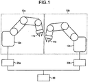
1 ist ein Schema zur Erläuterung eines Produktionssystems, das ein Robotersteuerungssystem in einer ersten Ausführungsform der vorliegenden Erfindung enthält. 1 Fig. 12 is a diagram for explaining a production system including a robot control system in a first embodiment of the present invention.
-
2 ist ein Schema zur Erläuterung der Konfiguration eines Robotersteuerungssystems nach einem Vergleichsbeispiel. 2 FIG. 12 is a diagram for explaining the configuration of a robot control system according to a comparative example. FIG.
-
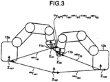
3 ist ein Schema zur Erläuterung eines idealen Positionsverhältnisses zwischen Endeffektoren. 3 FIG. 12 is a diagram for explaining an ideal positional relationship between end effectors. FIG.
-
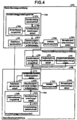
4 ist ein Schema zur Erläuterung der Konfiguration des Robotersteuerungssystems in der ersten Ausführungsform. 4 FIG. 12 is a diagram for explaining the configuration of the robot control system in the first embodiment. FIG.
-
5 ist ein Ablaufschema zur Erläuterung einer Vorbereitungsverarbeitung in der ersten Ausführungsform. 5 Fig. 10 is a flowchart for explaining preparation processing in the first embodiment.
-
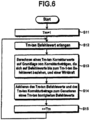
6 ist ein Ablaufschema zur Erläuterung eines Funktionsablaufs während eines Automatikbetriebs einer Master-Steuerungsvorrichtung in der ersten Ausführungsform. 6 FIG. 10 is a flowchart for explaining an operation during an automatic operation of a master control device in the first embodiment. FIG.
-
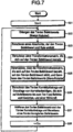
7 ist ein Ablaufschema zur Erläuterung eines Funktionsablaufs während eines Automatikbetriebs einer Slave-Steuerungsvorrichtung in der ersten Ausführungsform. 7 Fig. 10 is a flowchart for explaining an operation during an automatic operation of a slave control device in the first embodiment.
-
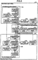
8 ist ein Schema zur Erläuterung der Konfiguration eines Robotersteuerungssystems in einer zweiten Ausführungsform. 8th Fig. 12 is a diagram for explaining the configuration of a robot control system in a second embodiment.
-
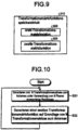
9 ist ein Schema zur Erläuterung einer Speicherkonfiguration einer Transformationsmatrixfunktionsspeichereinheit in der zweiten Ausführungsform. 9 FIG. 12 is a diagram for explaining a memory configuration of a transformation matrix function storage unit in the second embodiment. FIG.
-
10 ist ein Ablaufschema zur Erläuterung eines Funktionsablaufs, bei dem eine Positionsverhältnisberechnungseinheit in der zweiten Ausführungsform eine zweite Transformationsmatrixfunktion generiert. 10 FIG. 10 is a flowchart for explaining a flow of operation in which a position ratio calculation unit in the second embodiment generates a second transformation matrix function.
-
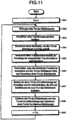
11 ist ein Ablaufschema zur Erläuterung eines Funktionsablaufs während eines Automatikbetriebs einer Slave-Steuerungsvorrichtung in der zweiten Ausführungsform. 11 Fig. 10 is a flowchart for explaining an operation during an automatic operation of a slave control device in the second embodiment.
-
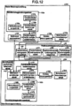
12 ist ein Schema zur Erläuterung der Konfiguration eines Robotersteuerungssystems in einer dritten Ausführungsform. 12 Fig. 12 is a diagram for explaining the configuration of a robot control system in a third embodiment.
-
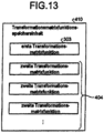
13 ist ein Schema zur Erläuterung einer Speicherkonfiguration einer Transformationsmatrixfunktionsspeichereinheit in der dritten Ausführungsform. 13 FIG. 12 is a diagram for explaining a memory configuration of a transformation matrix function storage unit in the third embodiment. FIG.
-
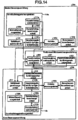
14 ist ein Schema zur Erläuterung der Konfiguration eines Robotersteuerungssystems in einer siebten Ausführungsform. 14 FIG. 12 is a diagram for explaining the configuration of a robot control system in a seventh embodiment. FIG.
-
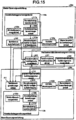
15 ist ein Schema zur Erläuterung einer anderen Konfiguration des Robotersteuerungssystems in der siebten Ausführungsform. 15 FIG. 12 is a diagram for explaining another configuration of the robot control system in the seventh embodiment. FIG.
-
16 ist ein Schema zur Erläuterung der Konfiguration eines Robotersteuerungssystems in einer achten Ausführungsform. 16 Fig. 12 is a diagram for explaining the configuration of a robot control system in an eighth embodiment.
-
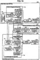
17 ist ein Schema eines Verhältnisses zwischen einer Wirkkraft, die an einen Endeffektor angelegt wird, und der Position des Endeffektors im Robotersteuerungssystem nach dem Vergleichsbeispiel. 17 FIG. 12 is a diagram of a relationship between an acting force applied to an end effector and the position of the end effector in the robot control system according to the comparative example.
-
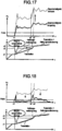
18 ist ein Schema eines Verhältnisses zwischen einer Wirkkraft, die an den Endeffektor angelegt wird, und der Position des Endeffektors bei einer Impedanzsteuerung, die auf das Robotersteuerungssystem nach dem Vergleichsbeispiel angewendet wird. 18 FIG. 12 is a diagram of a relationship between an acting force applied to the end effector and the position of the end effector in an impedance control applied to the robot control system of the comparative example.
-
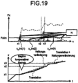
19 ist ein Schema eines Verhältnisses zwischen einer Wirkkraft, die an einen Endeffektor angelegt wird, und der Position des Endeffektors im Robotersteuerungssystem in der achten Ausführungsform. 19 FIG. 12 is a diagram of a relationship between an acting force applied to an end effector and the position of the end effector in the robot control system in the eighth embodiment.
Beschreibung der AusführungsformenDescription of the embodiments
Ausführungsformen einer Robotersteuerungsvorrichtung und eines Robotersteuerungsverfahrens nach der vorliegenden Erfindung werden nachstehend im Detail mit Bezug auf die Zeichnungen beschrieben. Anzumerken ist, dass die vorliegende Erfindung durch die Ausführungsformen nicht eingeschränkt wird.Embodiments of a robot control device and a robot control method according to the present invention will be described below in detail with reference to the drawings. It should be noted that the present invention is not limited by the embodiments.
Erste AusführungsformFirst embodiment
1 ist ein Schema zur Erläuterung eines Produktionssystems , das ein Robotersteuerungssystem (eine Robotersteuerungsvorrichtung) in einer ersten Ausführungsform der vorliegenden Erfindung enthält. Wie in der Figur gezeigt ist, umfasst das Robotersteuerungssystem einen Master-Roboter (einen ersten Roboter) 10a, einen Slave-Roboter (einen zweiten Roboter) 10b, eine Master-Steuerungsvorrichtung 20a, die den Master-Roboter 10a steuert, eine Slave-Steuerungsvorrichtung 20b, die den Slave-Roboter 10b steuert, und eine Positionsverhältnisberechnungsvorrichtung 30. Der Master-Roboter 10a ist so aufgebaut, dass ein Arm, der einen Endeffektor 11a an einem distalen Ende aufweist, an einem Installationsgestell 12a angebracht ist. Ähnlich ist der Slave-Roboter 10b so aufgebaut, dass ein Arm, der einen Endeffektor 11b an einem distalen Ende aufweist, an einem Installationsgestell 12b angebracht ist. Anzumerken ist, dass in der folgenden Erklärung als Beispiel davon ausgegangen wird, dass es sich bei den Robotern 10a und 10b um vertikale Mehrgelenkroboter mit sechs Freiheitsgraden handelt. 1 Fig. 12 is a diagram for explaining a production system including a robot control system (a robot control device) in a first embodiment of the present invention. As shown in the figure, the robot control system includes a master robot (a first robot) 10a , a slave robot (a second robot) 10b, a master control device 20a that the master robot 10a controls, a slave control device 20b that the slave robot 10b controls, and a positional relationship calculating device 30 , The master robot 10a is constructed so that an arm that has an end effector 11a at a distal end, on an installation rack 12a is appropriate. Similar is the slave robot 10b designed so that an arm that has an end effector 11b at a distal end, on an installation rack 12b is appropriate. It should be noted that in the following explanation, it is assumed as an example that it is the robots 10a and 10b is about vertical multi-joint robot with six degrees of freedom.
Die Master-Steuerungsvorrichtung 20a, die Slave-Steuerungsvorrichtung 20b und die Positionsverhältnisberechnungsvorrichtung 30 sind durch eine Kommunikationsleitung miteinander verbunden und bilden das Robotersteuerungssystem (die Robotersteuerungsvorrichtung), das den Master-Roboter 10a und den Slave-Roboter 10b ansteuert, während die Roboter miteinander synchronisiert werden. Die Master-Steuerungsvorrichtung 20a generiert Positionsbefehlswerte zum Positionieren des Endeffektors 11a und steuert den Endeffektor 11a auf Grundlage der generierten Positionsbefehlswerte an. Die Master-Steuerungsvorrichtung 20a überträgt die sich auf den Endeffektor 11a beziehenden Positionsbefehlswerte an die Slave-Steuerungsvorrichtung 20b. Die Positionsverhältnisberechnungsvorrichtung 30 berechnet Positionsverhältnisinformation, um ein Positionsverhältnis zwischen den Endeffektoren 11a und 11b während eines kooperativen Betriebs so festzulegen, dass der Endeffektor 11a und der Endeffektor 11b in Kooperation dasselbe Werkstück halten und das Werkstück (das ergriffene Werkstück) transportieren können. Die Positionsverhältnisberechnungsvorrichtung 30 überträgt die gewonnene Positionsverhältnisinformation an die Slave-Steuerungsvorrichtung 20b. Die Slave-Steuerungsvorrichtung 20b veranlasst, dass die Positionsverhältnisinformation zwischen den Endeffektoren 11a und 11b auf die Positionsbefehlswerte zum Positionieren des Endeffektors 11a wirkt, um Positionsbefehlswerte zum Positionieren des Endeffektors 11b zu berechnen. Die Slave-Steuerungsvorrichtung 20b steuert den Endeffektor 11b auf Grundlage der berechneten Positionsbefehlswerte an.The master control device 20a , the slave control device 20b and the positional relationship calculating device 30 are connected to each other by a communication line, and constitute the robot control system (the robot control device) that is the master robot 10a and the slave robot 10b controls while the robots are synchronized with each other. The master control device 20a generates position command values to position the end effector 11a and controls the end effector 11a based on the generated position command values. The master control device 20a transfers to the end effector 11a related position command values to the slave control device 20b , The position ratio calculation device 30 calculates position ratio information to a positional relationship between the end effectors 11a and 11b during a cooperative operation so to establish that the end effector 11a and the end effector 11b cooperatively hold the same workpiece and transport the workpiece (the gripped workpiece). The position ratio calculation device 30 transmits the obtained positional relationship information to the slave control device 20b , The slave control device 20b causes the position ratio information between the end effectors 11a and 11b to the position command values for positioning the end effector 11a acts to position command values to position the end effector 11b to calculate. The slave control device 20b controls the end effector 11b based on the calculated position command values.
Es wird eine Technologie im Vergleich zur ersten Ausführungsform der vorliegenden Erfindung (im Folgenden als Vergleichsbeispiel bezeichnet) erklärt. 2 ist ein Schema zur Erläuterung der Konfiguration eines Robotersteuerungssystems nach dem Vergleichsbeispiel. Anzumerken ist, dass, um das Vergleichsbeispiel von der ersten Ausführungsform zu unterscheiden, eine Positionsverhältnisberechnungsvorrichtung, auf die das Vergleichsbeispiel angewendet wird, mit dem Bezugszeichen 50 bezeichnet ist, eine Master-Steuerungsvorrichtung, auf die das Vergleichsbeispiel angewendet wird, mit dem Bezugszeichen 40a bezeichnet ist, und eine Slave-Steuerungsvorrichtung, auf die das Vergleichsbeispiel angewendet wird, mit dem Bezugszeichen 40b bezeichnet ist. Was die Komponenten betrifft, die in der Master-Steuerungsvorrichtung 40a und der Slave-Steuerungsvorrichtung 40b enthalten sind und dieselben Funktionen mit dem einzigen Unterschied dahingehend haben, ob es sich bei einem agierenden Ziel um ein Master-System (den Master-Roboter 10a und die Master-Steuerungsvorrichtung 40a) oder ein Slave-System (einen Slave-Roboter 10b und die Slave-Steuerungsvorrichtung 40b) handelt, werden die Komponenten voneinander unterschieden, indem ein Buchstabe „a“ zu den Bezugszahlen hinzugefügt wird, wenn die Komponenten im Master-System enthalten sind, und ein Buchstabe „b“ den Bezugszahlen hinzugefügt wird, wenn die Komponenten im Slave-System enthalten sind. Was zwei Komponenten betrifft, die dieselbe Funktion haben, sich aber nur in den Systemen unterscheiden, in denen sie enthalten sind, wird in manchem Fall nur eine der Komponenten erklärt und die Erklärung der anderen weggelassen.A technology compared with the first embodiment of the present invention (hereinafter referred to as a comparative example) will be explained. 2 FIG. 12 is a diagram for explaining the configuration of a robot control system according to the comparative example. FIG. Note that in order to distinguish the comparative example from the first embodiment, a positional relationship calculating apparatus to which the comparative example is applied is denoted by the reference numeral 50 is a master control device to which the comparative example is applied, with the reference numeral 40a and a slave control device to which the comparative example is applied by the reference numeral 40b is designated. As for the components involved in the master control device 40a and the slave control device 40b are contained and have the same functions with the sole difference that an acting target is a master system (the master robot 10a and the master control device 40a) or a slave system (a slave robot 10b and the slave control device 40b) the components are distinguished from each other by adding a letter "a" to the reference numbers when the components are included in the master system and adding a letter "b" to the reference numbers when the components are included in the slave system , As for two components having the same function but differing only in the systems in which they are contained, in some cases only one of the components is explained and the explanation of the others is omitted.
Die Master-Steuerungsvorrichtung 40a umfasst eine Befehlswertspeichereinheit 100, die vorab M Positionsbefehlswerte speichert, um eine Befehlsbahn des Endeffektors 11a in jedem der Betriebszeiträume zu definieren, eine Korrekturbetraggenerierungseinheit 102a, die einen Korrekturbetrag (einen Tm-ten Korrekturbetrag) für einen Tm-ten (Tm ist eine ganze Zahl, die 1≤Tm≤M erfüllt) Befehlswert (einen Tm-ten Befehlswert) unter den M Positionsbefehlswerten (im Folgenden einfach als Befehlswerte bezeichnet) berechnet, eine Generierungseinheit 101a für korrigierte Befehlswerte, die auf Grundlage des Tm-ten Befehlswerts und des Tm-ten Korrekturbetrags einen Tm-ten korrigierten Befehlswert generiert, der durch Korrigieren des Tm-ten Befehlswerts erhalten wird, eine Antriebssteuerungseinheit 103a, die einen Servoverstärker und einen Servomotor umfasst, der den Master-Roboter 10a so antreibt, dass der Endeffektor 11a den Tm-ten korrigierten Befehlswert annimmt, und eine Momentanpositionserfassungseinheit 104a, die einen Messgeber umfasst, der eine Erfassung der momentanen Position (einer Tm-ten Momentanposition) des Endeffektors 11a im Betrieb auf Grundlage des Tm-ten korrigierten Befehlswerts durchführt und die Tm-te Momentanposition an die Antriebssteuerungseinheit 103a zurückleitet.The master control device 40a includes a command value storage unit 100 which pre-stores M position command values to a command path of the end effector 11a in each of the operating periods, a correction amount generation unit 102 indicative of a correction amount (a Tm-th correction amount) for a Tm-th (Tm is an integer satisfying 1≤Tm≤M) command value (a Tm-th command value) among the M position command values (hereinafter simply referred to as command values ), a generation unit 101 for corrected command values, which generates, based on the Tm-th command value and the Tm-th correction amount, a Tm-th corrected command value obtained by correcting the Tm-th command value, a drive control unit 103a , which includes a servo amplifier and a servomotor, which is the master robot 10a so that drives the end effector 11a takes the Tm-th corrected command value, and a current position detecting unit 104a comprising a transducer which detects the current position (a Tm-th instantaneous position) of the end effector 11a in operation based on the Tm-th corrected command value and the Tm-th instantaneous position to the drive control unit 103a feeds back.
Die Korrekturbetraggenerierungseinheit 102a umfasst eine Wirkkraftberechnungseinheit 105a, eine Korrekturbetragberechnungseinheit 106a und eine Korrekturbetragspeichereinheit 107a. Die Wirkkraftberechnungseinheit 105a berechnet eine Wirkkraft, die im Endeffektor 11a erzeugt wird. Die Korrekturbetragspeichereinheit 107a akkumuliert und speichert berechnete Korrekturbeträge (d.h. den T1-ten Korrekturbetrag bis Tm-1-ten Korrekturbetrag). Die Korrekturbetragberechnungseinheit 106a berechnet den Tm-ten Korrekturbetrag unter Verwendung des T1-ten bis Tm-1-ten Korrekturbetrags, um die im Endeffektor 11a erzeugte Kraft zu reduzieren. Der berechnete Tm-te Korrekturbetrag wird an die Generierungseinheit 101a für korrigierte Befehlswerte übertragen und in der Korrekturbetragspeichereinheit 107a gespeichert.The correction amount generation unit 102 comprises an active force calculation unit 105a , a correction amount calculation unit 106a and a correction amount storage unit 107a , The effective power calculation unit 105a calculates a potency in the end effector 11a is produced. The correction amount storage unit 107a accumulates and stores calculated correction amounts (ie, the T1-th correction amount to Tm-1th correction amount). The correction amount calculation unit 106a calculates the Tm-th correction amount using the T1th to Tm-1th correction amount, that in the end effector 11a reduce generated force. The calculated Tm-th correction amount is sent to the generation unit 101 for corrected command values and in the correction amount storage unit 107a saved.
Die Positionsverhältnisberechnungsvorrichtung 50 berechnet eine Matrix (eine Transformationsmatrix), um ein Positionsverhältnis zwischen einem Befehlswert zum Positionieren des Endeffektors 11a und einem Befehlswert zum Positionieren des Endeffektors 11b zu definieren. Die Positionsverhältnisberechnungsvorrichtung 50 kann den Befehlswert zum Positionieren des Endeffektors 11b erhalten, indem sie bewirkt, dass die Transformationsmatrix auf den Befehlswert zum Positionieren des Endeffektors 11a wirkt.The position ratio calculation device 50 calculates a matrix (a transformation matrix) to obtain a positional relationship between a command value for positioning the end effector 11a and a command value for positioning the end effector 11b define. The position ratio calculation device 50 can use the command value to position the end effector 11b obtained by causing the transformation matrix to the command value to position the end effector 11a acts.
Die Slave-Steuerungsvorrichtung 40b umfasst eine Transformationsmatrixspeichereinheit 109, die eine durch die Positionsverhältnisberechnungsvorrichtung 50 berechnete Transformationsmatrix speichert, eine Befehlswertgenerierungseinheit 108, die bewirkt, dass die durch die Transformationsmatrixspeichereinheit 109 gespeicherte Transformationsmatrix auf den Tm-ten Befehlswert zum Positionieren des Endeffektors 11a wirkt, um einen Tm-ten Befehlswert zum Positionieren des Endeffektors 11b zu generieren, eine Korrekturbetraggenerierungseinheit 102b, die einen Tm-ten Korrekturbetrag zum Korrigieren des Tm-ten Befehlswerts berechnet, der sich auf den Endeffektor 11b bezieht, eine Generierungseinheit 101b für korrigierte Befehlswerte, die einen Tm-ten korrigierten Befehlswert auf Grundlage des Tm-ten Befehlswerts und des Tm-ten Korrekturbetrags generiert, die sich auf den Endeffektor 11b beziehen, eine Antriebssteuerungsvorrichtung 103b, die einen Servoverstärker und einen Servomotor umfasst, der den Slave-Roboter 10b auf Grundlage des Tm-ten korrigierten Befehlswerts antreibt, der sich auf den Endeffektor 11b bezieht, und eine Momentanpositionserfassungseinheit 104b, die einen Messgeber umfasst, der eine Erfassung einer Tm-ten Momentanposition des Endeffektors 11b durchführt und die erfasste Tm-te Momentanposition an die Antriebssteuerungseinheit 103b zurückgibt. Die Korrekturbetraggenerierungseinheit 102b umfasst eine Konfiguration, bei der es sich um dieselbe wie die der Korrekturbetraggenerierungseinheit 102a handelt. Deshalb wird die Erklärung der Korrekturbetraggenerierungseinheit 102b weggelassen.The slave control device 40b includes a transformation matrix storage unit 109 passing through the positional relationship calculator 50 stores calculated transformation matrix, a command value generation unit 108 that causes through the transformation matrix storage unit 109 stored transformation matrix on the Tm-th command value for positioning the end effector 11a acts to set a Tm-th command value to position the end effector 11b generate a correction amount generation unit 102b calculating a Tm-th correction amount for correcting the Tm-th command value related to the end effector 11b refers to a generation unit 101b for corrected command values, which generates a Tm-th corrected command value based on the Tm-th command value and the Tm-th correction amount related to the end effector 11b relate, a drive control device 103b , which includes a servo amplifier and a servomotor, which is the slave robot 10b on the basis of the Tm -th corrected command value, which refers to the end effector 11b and a current position detection unit 104b comprising a transducer which detects a Tm-th instantaneous position of the end effector 11b and the detected Tm-th instantaneous position to the drive control unit 103b returns. The correction amount generation unit 102b includes a configuration that is the same as that of the correction amount generation unit 102 is. Therefore, the explanation of the correction amount generation unit becomes 102b omitted.
Nun wird die Transformationsmatrix erklärt, die durch die Positionsverhältnisberechnungsvorrichtung 50 berechnet wird. Die Transformationsmatrix wird allgemein homogene Transformationsmatrix genannt, die einen Rotationsbetrag und eine Position darstellt. Wenn ein orthogonales Koordinatensystem als Σi und eine Transformationsmatrix zwischen zwei orthogonalen Koordinatensystemen Σ1 und Σ2 als 1T2 dargestellt wird, wird, wenn eine Rotationsmatrix als 1R2 (eine quadratische Matrix aus 3 × 3 Elementen) dargestellt wird, die Position des orthogonalen Koordinatensystems Σ2 vom orthogonalen Koordinatensystem Σ1 aus gesehen, als 1P2 (ein Vektor aus 3 × 1 Elementen) dargestellt und ein Nullvektor von 1 × 3 als Null(1,3) dargestellt, wobei die homogene Transformationsmatrix wie durch die folgende Formel (1) angegeben dargestellt wird:
Now, the transformation matrix generated by the positional relationship calculating device will be explained 50 is calculated. The transformation matrix is generally called a homogeneous transformation matrix representing a rotation amount and a position. If an orthogonal coordinate system as .sigma..sub.i and a transformation matrix between two orthogonal coordinate systems Σ1 and Σ2 is represented as 1 T 2 , when a rotation matrix is represented as 1 R 2 (a square matrix of 3 × 3 elements), the position of the orthogonal coordinate system Σ2 from the orthogonal coordinate system Σ1 is represented as 1 P 2 (a vector of 3 × 1 elements) and a zero vector of 1 × 3 is represented as zero (1.3), the homogeneous transformation matrix being represented by the following formula (1):
Anzumerken ist, dass, wenn eine Positionshaltung eines Punkts „a“ als iTa im Hinblick auf ein Koordinatensystem Σi dargestellt wird, eine Positionshaltung i+1Ta des Punkts „a“ im Hinblick auf ein anderes Koordinatensystem Σi+1 wie durch die folgende Formel (2) angegeben unter Verwendung einer Transformationsmatrix i+1Ti aus Σi bis Σi+1 dargestellt ist.
It should be noted that when positional attitude of a point "a" as i T a with respect to a coordinate system .sigma..sub.i is shown, a positional attitude i + 1 T a of the point "a" with respect to another coordinate system Σi + 1 as indicated by the following formula (2) using a transformation matrix i + 1 T i .sigma..sub.i until Σi + 1 is shown.
3 ist ein Schema zur Erläuterung eines idealen Positionsverhältnisses zwischen den Endeffektoren 11a und 11b. Σrob1 ist ein Koordinatensystem (ein Master-Roboterkoordinatensystem) mit Bezug auf das Installationsgestell 12a, ∑rob2 ist ein Koordinatensystem (ein Slave-Roboterkoordinatensystem) mit Bezug auf das Installationsgestell 12b, ∑wld ist ein absolutes Koordinatensystem (ein Weltkoordinatensystem), ΣE1 ist ein Koordinatensystem mit Bezug auf den Endeffektor 11a, und ΣE2 ist ein Koordinatensystem mit Bezug auf den Endeffektor 11b. Eine ideale Umgebung ist eine Umgebung, in der ein Befehlswinkel und eine Befehlsposition miteinander übereinstimmen, mit anderen Worten, eine Umgebung ohne absoluten Positionsfehler. In einer solchen Umgebung kann die folgende Formel (3) als Transformationsmatrix zwischen dem Master und dem Slave verwendet werden. Anzumerken ist, dass „A-1“ eine Umkehrmatrix bezüglich einer Matrix A darstellt.
3 is a scheme for explaining an ideal positional relationship between the end effectors 11a and 11b , Σ rob1 is a coordinate system (a master robot coordinate system) with respect to the installation rack 12a . Σ rob2 is a coordinate system (a slave robot coordinate system) with respect to the installation rack 12b . Σ wld is an absolute coordinate system (a world coordinate system), Σ E1 is a coordinate system related to the end effector 11a , and Σ E2 is a coordinate system related to the end effector 11b , An ideal environment is an environment in which a command angle and a command position coincide with each other, in other words, an environment without absolute position error. In such an environment, the following formula (3) may be used as a transformation matrix between the master and the slave. It should be noted that "A -1 " represents an inverse matrix with respect to a matrix A.
Jedoch tritt in einer realen Umgebung ein absoluter Positionsfehler in Fingerpositionen der Endeffektoren 11a und 11b wegen eines Installationsfehlers, eines mechanischen Spiels, einer Biegung eines Arms, eines Fehlers der Endeffektoren 11a und 11b, dem Einfluss der Starrheit eines Verzögerungsglieds und dergleichen auf. Deshalb ist im Allgemeinen ein Positionsverhältnis zwischen den Fingerpositionen und einem Werkstück kein gewünschtes Positionsverhältnis. Beim Starten des Produktionssystems betätigt beispielsweise ein Benutzer eine nicht gezeigte Bedienkonsole zum Anlernen, um dadurch die realen Roboter 10a und 10b zu bewegen, während er ein Positionsverhältnis zwischen den Robotern 10a und 10b und dem Werkstück beispielsweise visuell prüft, um die Fehler so auf die Befehlswerte einzustellen, dass ein gewünschter Betrieb ausgeführt wird, während ein gewünschtes relatives Positionsverhältnis zwischen den Endeffektoren 11a und 11b eingehalten wird. Befehlswerte robiT'Ei (i = 1 und 2) in den Steuerungsvorrichtungen 20a und 20b zu den Zeitpunkten, zu denen der Benutzer die Endeffektoren 11a und 11b zu Stellen bewegt, an denen die Fehler reduziert sind, werden als Befehlswerte zum Positionieren der Endeffektoren 11a und 11b an den Anlernpunkten gesetzt. Anzumerken ist, dass „ ‘ “ einer Transformationsmatrix dort hinzugefügt wird, wo eine Positionsanpassung durch das Anlernen berücksichtigt wird.However, in a real environment, an absolute positional error occurs in finger positions of the endeffectors 11a and 11b due to an installation error, a mechanical play, a bend of an arm, a mistake of the end effectors 11a and 11b , the influence of the rigidity of a delay element, and the like. Therefore, in general, a positional relationship between the finger positions and a workpiece is not a desired positional relationship. For example, when starting the production system, a user operates an operator console, not shown, for teaching, thereby the real robots 10a and 10b while moving a positional relationship between the robots 10a and 10b and visually inspects the workpiece, for example, to adjust the errors to the command values so that a desired operation is performed while a desired relative positional relationship between the end effectors 11a and 11b is complied with. command values robi T ' egg (i = 1 and 2) in the control devices 20a and 20b at the times when the user has the end-effectors 11a and 11b moved to places where the errors are reduced as command values for positioning the end effectors 11a and 11b set at the learning points. It should be noted that "'" is added to a transformation matrix where positional adaptation by training is considered.
Die Befehlswerte robiT'Ei (i = 1 und 2), auf die die Fehler eingestellt werden, werden in die Positionsverhältnisberechnungsvorrichtung 50 eingegeben. Die Positionsverhältnisberechnungsvorrichtung 50 setzt Befehlswerte rob1T'E1 und rob2T'E2 nach der Einstellung in rob1TE1 bzw. rob2TE2 von Formel (3) ein und setzt das somit erhaltene E1TE2 gleich E1T'E2 .The command values robi T ' egg (i = 1 and 2) to which the errors are set are input to the positional relationship calculating device 50 entered. The position ratio calculation device 50 sets command values rob1 T ' E1 and rob2 T ' E2 after setting in rob1 T E1 respectively. rob2 T E2 of formula (3) and sets the thus obtained E1 T E2 equal E1 T ' E2 ,
Auf diese Weise wird E1T'E2 berechnet, bevor ein Normalbetrieb (synchrone Ansteuerung der Roboter 10a und 10b; im Folgenden auch als „Automatikbetrieb“ bezeichnet) anläuft. Das berechnete E1T'E2 wird als Transformationsmatrix zur Positionstransformation während des Automatikbetriebs verwendet. Das heißt, während des Automatikbetriebs wird in der Slave-Steuerungsvorrichtung 40b zum Zweck, einen Arbeitsvorgang zum Annehehmen eines korrigierten Befehlswerts der Master-Steuerungsvorrichtung 40a auszuführen, ein Befehlswert für den Endeffektor 11b in der Befehlswertgenerierungsvorrichtung 108 unter Verwendung eines Befehlswerts seitens der Master-Steuerungsvorrichtung 40a und der Transformationsmatrix generiert. In diesem Fall berechnet die Befehlswertgenerierungsvorrichtung 108 den Befehlswert rob2TE2 der Slave-Steuerungsvorrichtung 40b auf Grundlage der folgenden Formel (4), unter Verwendung einer Transformationsmatrix wldTrob1 in einem Master-Roboterkoordinatensystem in Bezug auf ein Weltkoordinatensystem, einer Transformationsmatrix wldTrob2 in einem Slave-Roboterkoordinatensystem in Bezug auf das Weltkoordinatensystem, und der Transformationsmatrix E1T'E2 .
This way will E1 T ' E2 calculated before normal operation (synchronous control of the robot 10a and 10b ; hereinafter referred to as "automatic mode") starts. The calculated E1 T ' E2 is used as a transformation matrix for position transformation during automatic operation. That is, during the automatic operation, in the slave control device 40b for the purpose of, a process of accepting a corrected command value of the master control device 40a a command value for the end effector 11b in the instruction value generating device 108 using a command value from the master controller 40a and the transformation matrix is generated. In this case, the command value generating device calculates 108 the command value rob2 T E2 the slave control device 40b based on the following formula (4), using a transformation matrix wld T rob1 in a master robot coordinate system with respect to a world coordinate system, a transformation matrix wld T rob2 in a slave robot coordinate system with respect to the world coordinate system, and the transformation matrix E1 T ' E2 ,
Im Vergleichsbeispiel wird jedoch die Transformationsmatrix, die zur Transformation des Befehlswerts zwischen dem Master und dem Slave verwendet wird, auf E1T'E2 festgesetzt, die am Anlernpunkt bei einer spezifischen Roboterhaltung berechnet wurde. Deshalb ist es, selbst wenn der Befehlswert auf Grundlage einer Wirkkraft korrigiert wird, schwierig, ein Positionsverhältnis zwischen den Robotern oder zwischen den Robotern und dem Werkstück an allen Positionen auf Bahnen im kooperativen Betrieb in einem festgelegten Zustand zu halten. Deshalb wird in der ersten Ausführungsform die Transformationsmatrix E1T'E2 für die jeweiligen M Befehlswerte so berechnet, dass das Positionsverhältnis zwischen den Robotern oder zwischen den Robotern und dem Werkstück an allen Positionen auf den Bahnen im kooperativen Betrieb beibehalten werden kann.However, in the comparative example, the transformation matrix used to transform the command value between the master and the slave will be on E1 T ' E2 fixed at the learning point in a specific robot attitude. Therefore, even if the command value is corrected based on an effective force, it is difficult to maintain a positional relationship between the robots or between the robots and the workpiece at a fixed state at all positions on tracks in the cooperative operation. Therefore, in the first embodiment, the transformation matrix becomes E1 T ' E2 for the respective M command values calculated so that the positional relationship between the robots or between the robots and the workpiece at all positions on the tracks in cooperative operation can be maintained.
4 ist ein Schema zur Erläuterung eines Robotersteuerungssystems in der ersten Ausführungsform der vorliegenden Erfindung, das eine Positionsverhältnisberechnungsvorrichtung umfasst. Komponenten, die dieselben Funktionen wie im Vergleichsbeispiel haben, sind mit denselben Bezugszahlen und Bezugszeichen bezeichnet und eine redundante Erklärung der Komponenten wird weggelassen. 4 Fig. 12 is a diagram for explaining a robot control system in the first embodiment of the present invention, which includes a position ratio calculating device. Components having the same functions as in the comparative example are denoted by the same reference numerals and reference numerals, and a redundant explanation of the components is omitted.
Wie in der Figur gezeigt ist, umfasst die Master-Steuerungsvorrichtung 20a die Befehlswertspeichereinheit 100, die Korrekturbetraggenerierungseinheit 102a, die Generierungseinheit 101a für korrigierte Befehlswerte, die Antriebssteuerungseinheit 103a und die Momentanpositionserfassungseinheit 104a. Die Korrekturbetraggenerierungseinheit 102a umfasst die Wirkkraftberechnungseinheit 105a, die Korrekturbetragberechnungseinheit 106a und die Korrekturbetragspeichereinheit 107a.As shown in the figure, the master control device comprises 20a the command value storage unit 100 , the correction amount generation unit 102 , the generation unit 101 for corrected command values, the drive control unit 103a and the current position detection unit 104a , The correction amount generation unit 102 includes the active power calculation unit 105a , the correction amount calculation unit 106a and the correction amount storage unit 107a ,
Die Positionsverhältnisberechnungseinheit 30 umfasst eine Transformationsmatrixgenerierungseinheit 200, die auf Grundlage von Befehlswerten zum Positionieren an N (N ist eine natürliche Zahl kleiner als M und gleich oder kleiner als 2) Anlernpunkten, die eine Betriebsstartposition beinhalten, Transformationsmatrizes (Transformationsmatrizes zum Anlernen) berechnet, die die jeweiligen Anlernpunkte betreffen, eine Transformationsmatrixspeichereinheit 201, die N Transformationsmatrizes zum Anlernen speichert, und eine Transformationsmatrixfunktionsgenerierungseinheit 202, die eine Transformationsmatrixfunktion auf Grundlage der N Transformationsmatrizes zum Anlernen berechnet. Details der Transformationsmatrixfunktion werden nachstehend erklärt. Die berechnete Transformationsmatrixfunktion wird in der ersten Ausführungsform als Positionsverhältnisinformation an die Slave-Steuerungsvorrichtung 20b übertragen.The positional relationship calculation unit 30 includes a transformation matrix generation unit 200 which is based on command values for positioning at N (N is a natural number less than M and equal to or less than 2) of learning points including an operation start position, transformation matrices (transformation matrices for learning) relating to the respective teach points, a transformation matrix storage unit 201 , which stores N transformation matrices for training, and a transformation matrix function generation unit 202 which computes a transformation matrix function based on the N transformation matrices for training. Details of the transformation matrix function will be explained below. The calculated transformation matrix function becomes positional information to the slave control device in the first embodiment 20b transfer.
Die Slave-Steuerungsvorrichtung 20b umfasst eine Transformationsmatrixfunktionsspeichereinheit 210, die die Transformationsmatrixfunktion speichert, die durch die Positionsverhältnisberechnungsvorrichtung 30 berechnet wird, eine Befehlswertgenerierungseinheit 211, die auf Grundlage des Tm-ten Befehlswerts (eines ersten Befehlswerts zum Ansteuern) für den Endeffektor 11a und der Transformationsmatrixfunktion einen Tm-ten Befehlswert (einen zweiten Befehlswert zum Ansteuern) zum Positionieren des Endeffektors 11b generiert, die Korrekturbetraggenerierungseinheit 102b, die Generierungseinheit 101b für korrigierte Befehlswerte, die Antriebssteuerungseinheit 103b und die Momentanpositionserfassungseinheit 104b. Die Korrekturbetraggenerierungseinheit 102b umfasst eine der Konfiguration der Korrekturbetraggenerierungseinheit 102a entsprechende Auslegung.The slave control device 20b includes a transformation matrix function storage unit 210 storing the transformation matrix function generated by the positional relationship calculator 30 is calculated, a command value generation unit 211 based on the Tm-th command value (a first command value for driving) for the end effector 11a and the transformation matrix function has a Tm-th command value (a second command value for driving) for positioning the end effector 11b generates the correction amount generation unit 102b , the generation unit 101b for corrected command values, the drive control unit 103b and the current position detection unit 104b , The correction amount generation unit 102b includes one of the configuration of the correction amount generation unit 102 appropriate interpretation.
Gemäß der ersten Ausführungsform kooperieren die Generierungseinheiten 101a und 101b für korrigierte Befehlswerte und die Korrekturbetraggenerierungseinheiten 102a und 102b miteinander, um als eine Generierungseinheit für positionskorrigierte Befehlswerte zu fungieren, die einen positionskorrigierten Befehlswert (einen Befehlswert zum Anlernen oder einen nachstehend erklärten ersten Befehlswert zum Anlernen) für jeden von auf Bahnen positionierten Robotern bei den jeweiligen N Befehlswerten während der gleichzeitigen Ansteuerung generiert. Die Befehlswertspeichereinheit 100 fungiert als Erstbefehlswertausgabeeinheit, die einen Befehlswert (einen ersten Befehlswert zum Ansteuern) in jedem von M (M>N) Betriebszeiträumen ausgibt, um eine Bahn des Endeffektors 11a zu definieren. Anzumerken ist, dass in der folgenden Erklärung davon ausgegangen wird, dass die Befehlswertspeichereinheit 100 einen Befehlswert vorab speichert und den gespeicherten Befehlswert ausgibt. Jedoch kann auch eine Funktionseinheit, die einen Befehlswert sequentiell auf Grundlage einer vorbestimmten Berechnung generiert, als die Ausgabeeinheit für den ersten Befehlswert übernommen werden. Die Transformationsmatrixfunktionsgenerierungseinheit 202 und die Befehlswertgenerierungseinheit 211 kooperieren miteinander, um als eine Positionsverhältnismatrixinterpolationseinheit zu fungieren, die die N Transformationsmatrizes interpoliert und eine Transformationsmatrix für jeden der Befehlswerte für den Endeffektor 11a generiert. Die Befehlswertgenerierungseinheit 211 fungiert als eine Generierungseinheit für zweite Befehlswerte, die bewirkt, dass die Transformationsmatrix nach der Interpolation in jedem der Betriebszeiträume auf die jeweiligen Befehlswerte wirkt, um M Befehlswerte (zweite Befehlswerte zum Ansteuern) zum Definieren einer Bahn des Endeffektors 11b zu generieren.According to the first embodiment, the generation units cooperate 101 and 101b for corrected command values and the correction amount generation units 102 and 102b with each other to function as a position corrected command value generating unit that generates a position corrected command value (a command value for teaching or a first instructing command value explained below) for each of on-line positioned robots at the respective N command values during the simultaneous driving. The command value storage unit 100 functions as a first instruction value output unit which outputs a command value (a first command value for driving) in each of M (M> N) operation periods, around a path of the end effector 11a define. It should be noted that in the following explanation it is assumed that the command value storage unit 100 pre-stores a command value and outputs the stored command value. However, a functional unit that generates a command value sequentially based on a predetermined calculation may be adopted as the output unit for the first command value. The transformation matrix function generation unit 202 and the command value generation unit 211 cooperate with each other to function as a positional relationship matrix interpolation unit that interpolates the N transformation matrices and a transformation matrix for each of the command values for the end effector 11a generated. The command value generation unit 211 acts as a second command value generation unit that causes the transformation matrix after interpolation to act on the respective command values in each of the operation periods to obtain M command values (second command values for driving) for defining a path of the end effector 11b to generate.
Ein Robotersteuerungsverfahren in der ersten Ausführungsform der vorliegenden Erfindung, das unter Verwendung des in 4 gezeigten Robotersteuerungssystems durchgeführt wird, wird nun erklärt. 5 ist ein Ablaufschema zur Erläuterung einer Vorbereitungsverarbeitung, die in dem Robotersteuerungsverfahren in der ersten Ausführungsform offline erfolgt.A robot control method in the first embodiment of the present invention using the method described in FIG 4 will now be explained. 5 FIG. 10 is a flowchart for explaining preparatory processing that takes place offline in the robot control method in the first embodiment.
Zuerst bewegt der Benutzer die Endeffektoren 11a und 11b unter Verwendung der Bedienkonsole zu den Anlernpunkten auf Bahnen während eines kooperativen Betriebs zum Anlernen oder dergleichen (Schritt S1). In diesem Fall kann der Benutzer beispielsweise bewirken, dass die Endeffektoren 11a und 11b tatsächlich ein Werkstück ergreifen, um Fingerpositionen der Endeffektoren 11a und 11b einzustellen, und dass die Steuervorrichtungen 20a und 20b Positionen an diesem Punkt erfassen. Anzumerken ist, dass die Positionsanpassung an jeweiligen N Anlernpunkten durchgeführt wird.First, the user moves the end effectors 11a and 11b using the control panel to the training points on tracks during a cooperative learning operation or the like (step S1 ). In this case, for example, the user may cause the end-effectors 11a and 11b actually take a workpiece to finger positions of the end effectors 11a and 11b adjust, and that the control devices 20a and 20b Capture positions at this point. It should be noted that the position adjustment is carried out at respective N teaching points.
Die Generierungseinheit 101a für korrigierte Befehlswerte speichert eine Position des Endeffektors 11a, die an einem Tk-ten (Tk ist eine ganze Zahl, die 1≤Tk≤N erfüllt) Anlernpunkt eingenommen wird, in der Befehlswertspeichereinheit 100 als einen Tk-ten Befehlswert (Befehlswert zum Anlernen), der sich auf den Master-Roboter 10a bezieht, und gibt den Befehlswert zum Anlernen an die Positionsverhältnisberechnungsvorrichtung 30 aus (Schritt S2). Die Generierungseinheit 101b für korrigierte Befehlswerte gibt die Position des Endeffektors 11b, der dem Schritt S2 unterzogen wird, an die Positionsverhältnisberechnungsvorrichtung 30 als einen auf den Slave-Roboter 10b bezogenen Tk-ten Befehlswert zum Anlernen aus (Schritt S3).The generation unit 101 for corrected command values stores a position of the end effector 11a which is taken at a Tk-th (Tk is an integer satisfying 1≤Tk≤N) in the command value storage unit 100 as a Tk-th command value (teach-in command value) that refers to the master robot 10a and gives the instruction value for teaching to the positional relationship calculator 30 out (step S2 ). The generation unit 101b for corrected command values gives the position of the end effector 11b that's the step S2 is subjected to the position ratio calculation device 30 as one on the slave robot 10b Tk-th instruction value for learning (step S3 ).
Anzumerken ist, dass, wenn bewirkt wird, dass die Endeffektoren 11a und 11b das Werkstück tatsächlich ergreifen, um die Positionsanpassung durchzuführen, die Korrekturbetragsgenerierungseinheit 102a die Berechnung eines Korrekturbetrags fortsetzt, bis die durch die Wirkkraftberechnungseinheit 105a berechnete Wirkkraft so korrigiert ist, dass sie gleich einem oder kleiner als ein vorbestimmter Wert ist. Die Generierungseinheit 101a für korrigierte Befehlswerte kann mit einem sequentiell berechneten Korrekturbetrag einen Korrekturbetrag aktualisieren, der zu dem aus der Befehlswertspeichereinheit 100 gelieferten vorbestimmten Befehlswert hinzuaddiert wird, und kann, wenn ein korrigierter Befehlswert, mit dem die Wirkkraft gleich dem oder kleiner als der vorbestimmte Wert wird, erreicht wird, den korrigierten Befehlswert als einen Befehlswert zum Anlernen setzen. Anzumerken ist, dass die Messung einer Wirkkraft, die Berechnung eines Korrekturbetrags auf Grundlage der gemessenen Wirkkraft und die Korrektur eines Befehlswerts mit dem berechneten Korrekturbetrag auf dieselbe Weise auch in der Slave-Steuerungsvorrichtung 20b durchgeführt werden. Ein erhaltener korrigierter Befehlswert wird als Befehlswert zum Anlernen durch die Verarbeitung im Schritt S3 ausgegeben. Anzumerken ist, dass es sich bei einem Korrekturwert, der den Generierungseinheiten 101a und 101b für korrigierte Befehlswerte während der Anpassung der Position provisorisch bereitgestellt wird, um einen vorbestimmten, feststehenden Wert handeln kann.It should be noted that when it causes the end-effectors 11a and 11b actually take the workpiece to perform the position adjustment, the correction amount generation unit 102 the calculation of a correction amount continues until the calculation by the active force calculation unit 105a calculated acting force is corrected so that it is equal to or less than a predetermined value. The generation unit 101 for corrected command values, with a sequentially calculated correction amount, a correction amount corresponding to that obtained from the command value storage unit may be updated 100 supplied with the predetermined command value supplied, and when a corrected command value with which the acting force becomes equal to or less than the predetermined value is reached, may set the corrected command value as a command value for teaching. It should be noted that the measurement of an active force, the calculation of a correction amount based on the measured effective force, and the correction of a command value with the calculated correction amount are also performed in the slave control device in the same manner 20b be performed. An obtained corrected command value is used as a command value for teaching by the processing in step S3 output. It should be noted that it is a correction value that the generation units 101 and 101b is provisionally provided for corrected command values during the adjustment of the position, which may be a predetermined, fixed value.
Ein Messverfahren für eine Wirkkraft durch die Wirkkraftberechnungseinheit 105a kann ein beliebiges Verfahren sein. Beispielsweise ist es möglich, ein Verfahren zu übernehmen, bei dem ein Kraftsensor an einem Handgelenkabschnitt eines Roboters befestigt und ein Erfassungswert durch den Kraftsensor als Messwert einer Wirkkraft gesetzt wird, oder es kann ein Verfahren übernommen werden, bei dem eine Fingerwirkkraft f (3 Achsenkräfte + 3 Momente) mit Statik aus einem Drehmoment τ unter Verwendung einer Jacobimatrix J (ein Freiheitsgrad des Roboters) geschätzt wird (τ = JT * f, worin JT eine transponierte Matrix einer Matrix J ist). Ferner ist es möglich, ein Verfahren zu übernehmen, bei dem Drehmomente von Wellen von Robotern 10a und 10b aus Motorströmen der Wellen berechnet werden und eine Fingerwirkkraft aus Ausgaben der berechneten Drehmomente geschätzt wird, oder ein Verfahren, bei dem Drehmomentsensoren an den Wellen angebracht werden und eine Wirkkraft aus ausgegebenen Drehmomenten geschätzt wird, die aus den Drehmomentsensoren anstelle der Motorströme erhalten werden. A measuring method for an effective force by the effective force calculation unit 105a can be any method. For example, it is possible to adopt a method in which a force sensor is attached to a wrist portion of a robot and a detection value is set by the force sensor as a measure of an effective force, or a method in which a finger force f (3 axis forces + 3 moments) with statics from a torque τ using a Jacobian J (one degree of freedom of the robot) is estimated (τ = J T * f, where J T is a transposed matrix of a matrix J). Further, it is possible to adopt a method in which torques of shafts of robots 10a and 10b is calculated from motor currents of the waves and a finger action force estimated from outputs of the calculated torques, or a method in which torque sensors are attached to the shafts and an action force is estimated from output torques obtained from the torque sensors instead of the motor currents.
Anzumerken ist, dass in der folgenden Erklärung davon ausgegangen wird, dass die Endeffektoren 11a und 11b dazu veranlasst werden, das Werkstück tatsächlich zu ergreifen, um eine Positionsanpassung durchzuführen, und ein korrigierter Befehlswert als ein Befehlswert zum Anlernen aufgezeichnet wird. Allerdings kann, wenn die Positionsanpassung durchgeführt wird, ohne zu bewirken, dass die Endeffektoren 11a und 11b das Werkstück ergreifen, die Generierungseinheit 101a für korrigierte Befehlswerte als Befehlswert zum Anlernen einen Positionserfassungswert ansetzen, der durch die Momentanpositionserfassungseinheit 104a erfasst und als Rückkopplungssignal verwendet wird. Selbiges trifft auf die Slave-Steuerungsvorrichtung 20b zu. Selbst wenn bewirkt wird, dass die Endeffektoren 11a und 11b das Werkstück tatsächlich ergreifen, um die Positionsanpassung durchzuführen, kann ein durch die Momentanpositionserfassungseinheiten 104a und 104b erfasster Positionserfassungswert als der Befehlswert zum Anlernen angesetzt werden.It should be noted that the following explanation assumes that the end effectors 11a and 11b is actually caused to take the workpiece to perform a position adjustment, and a corrected command value is recorded as a command value for teaching. However, if the position adjustment is performed without causing the end effectors 11a and 11b grab the workpiece, the generation unit 101 For corrected command values, as instruction value for teaching, set a position detection value that is detected by the current position detection unit 104a detected and used as a feedback signal. The same applies to the slave control device 20b to. Even if it causes the end-effectors 11a and 11b Actually engage the workpiece to perform the position adjustment may be performed by the current position detection units 104a and 104b detected position detection value can be set as the instruction value for teaching.
Wenn die Steuerungsvorrichtungen 20a und 20b keine Einrichtungen zum Messen einer Wirkkraft umfassen, kann ein Benutzer die Position des Endeffektors 11b jedes Mal dann manuell fein einstellen, wenn sich eine Arbeitsfläche oder eine Haltung verändert. In diesem Fall kann die Slave-Steuerungsvorrichtung 20b den Endeffektor 11b ansteuern, indem sie bewirkt, dass eine festgelegte Transformationsmatrix 1ET'E2 , die vorab provisorisch angesetzt wird, auf einen Anlernpunkt für den Master-Roboter 10a wirkt. Der Benutzer kann jedes Mal, wenn sich eine Haltung oder eine Position verändert, einen Zustand des Werkstücks visuell oder indem ein Sensor, der eine Kraft oder Verformung erfassen kann, zum Werkstück hinzugefügt wird, beobachten, und kann eine Feineinstellung unter Verwendung der Bedienkonsole auf Grundlage des Ergebnisses der Beobachtung durchführen. Anzumerken ist, dass ein Zustand, in dem eine Wirkkraft nicht gemessen werden kann, entweder dann vorliegt, wenn schlichtweg kein Sensor zum Messen der Wirkkraft in den Endeffektoren 11a und 11b und keine Funktion zum Durchführen einer Fingerwirkkraftberechnung aus einem Motorausgang vorhanden ist oder wenn während des kooperativen Betriebs der master-seitige Roboter mit dem Werkstück in Kontakt ist aber der slave-seitige Roboter nicht mit dem Werkstück in Kontakt ist.When the control devices 20a and 20b do not include means for measuring an active force, a user may determine the position of the end effector 11b then manually fine tune each time a work surface or posture changes. In this case, the slave control device 20b the end effector 11b by causing a fixed transformation matrix 1E T ' E2 , which is provisionally set in advance, to a learning point for the master robot 10a acts. The user can observe a state of the workpiece visually or by adding a sensor capable of detecting force or deformation to the workpiece each time a posture or position changes, and can fine-tune using the operating panel based on to carry out the result of observation. It should be noted that a condition in which an effective force can not be measured exists either when there is simply no sensor for measuring the effective force in the end effectors 11a and 11b and there is no function to perform a finger force calculation from a motor output, or if, during cooperative operation, the master-side robot is in contact with the workpiece but the slave-side robot is not in contact with the workpiece.
Der Benutzer bestimmt, ob die Positionsanpassung für alle (N) Anlernpunkte durchgeführt wird (Schritt S4). Wenn die alle Anlernpunkte betreffende Positionsanpassung nicht durchgeführt wird (NEIN im Schritt S4), führt der Benutzer im Schritt S1 eine Positionsanpassung für den nächsten Anlernpunkt durch.The user determines whether the position adjustment is performed for all (N) teach points (step S4 ). If the position adjustment concerning all the teach points is not performed (NO in step S4 ), the user guides in the step S1 a position adjustment for the next learning point by.
Aus diese Weise wird der Endeffektor 11a zum Anlernpunkt bewegt, und der Endeffektor 11b wird zu einer Position bewegt, die dem Endeffektor 11a am Anlernpunkt entspricht. Folglich ist es möglich, Befehlswerte zu erhalten, an die der absolute Positionsfehler (positionskorrigierte Befehlswerte) in den jeweiligen N Befehlswerten auf den Bahnen der Endeffektoren 11a und 11b angepasst wird.This way, the end effector 11a moved to the learning point, and the end effector 11b is moved to a position corresponding to the end effector 11a at the learning point. Consequently, it is possible to obtain command values to which the absolute position error (position corrected command values) in the respective N command values on the trajectories of the end effectors 11a and 11b is adjusted.
Wenn die Positionsanpassung für alle Anlernpunkte abgeschlossen ist (JA im Schritt S4), empfängt in der Positionsverhältnisberechnungsvorrichtung 30 die Transformationsmatrixgenerierungseinheit 200 als Eingaben den Tk-ten Befehlswert zum Anlernen und den korrigierten Befehlswert, der durch die Generierungseinheit 101b für korrigierte Befehlswerte an dem Punkt generiert wird, an dem der Tk-te Befehlswert zum Anlernen bestimmt wird, und generiert eine Tk-te Transformationsmatrix (Transformationsmatrix zum Anlernen) (Schritt S5). Anzumerken ist, dass die Transformationsmatrixgenerierungseinheit 200 die generierte Transformationsmatrix zum Anlernen in der Transformationsmatrixspeichereinheit 201 speichert. Die Generierung der Transformationsmatrix zum Anlernen erfolgt die jeweiligen N Anlernpunkte betreffend.When the position adjustment for all teaching points is completed (YES in step S4 ) receives in the position ratio calculation device 30 the transformation matrix generation unit 200 as inputs, the Tk-th command value for training and the corrected command value generated by the generation unit 101b is generated for corrected command values at the point where the Tk-th command value for training is determined, and generates a Tk-th transformation matrix (transformation matrix for training) (step S5 ). It should be noted that the transformation matrix generation unit 200 the generated transformation matrix for training in the transformation matrix storage unit 201 stores. The generation of the transformation matrix for teaching takes place with regard to the respective N learning points.
Anschließend generiert die Transformationsmatrixfunktionsgenerierungseinheit 202 eine Transformationsmatrixfunktion auf Grundlage der N Transformationsmatrizes zum Anlernen, die in der Transformationsmatrixspeichereinheit 201 gespeichert sind (Schritt S6).Subsequently, the transformation matrix function generation unit generates 202 a transformation matrix function based on the N transformation matrices for training that are in the transformation matrix storage unit 201 are stored (step S6 ).
Bei der Transformationsmatrixfunktion handelt es sich um eine Funktion, um eine Transformationsmatrixgruppe zum Interpolieren von N Transformationsmatrizes E1T'E2 (k), k=1, 2, ..., N zu spezifizieren. Eine gesamte Bahn wird auf Grundlage der N Befehlswerte zum Anlernen in N-1 Abschnitte unterteilt. Die Funktion besitzt Bewegungsraten „Rate“ in den jeweiligen Abschnitten als Variablen. Ein Berechnungsverfahren für eine Transformationsmatrixfunktion durch die Transformationsmatrixfunktionsgenerierungseinheit 202 wird nachstehend erklärt. The transformation matrix function is a function to form a transformation matrix group for interpolating N transformation matrices E1 T ' E2 (k), k = 1, 2, ..., N to specify. An entire orbit is divided into N-1 sections based on the N command values for training. The function has rate of movement rates "rate" in the respective sections as variables. A calculation method for a transformation matrix function by the transformation matrix function generation unit 202 will be explained below.
Wenn ein Abstand zwischen einem k-ten Befehlswert zum Anlernen von Pk und einem k+1-ten Befehlswert zum Anlernen von Pk+1 als La11(k, k+1) und eine Restbewegungsstrecke zur momentanen Zeit Tnow als Lr (k, k+1, Tnow) dargestellt wird, wird eine Bewegungsrate Rate (k, k+1, Tnow) gemäß folgender Formel (5) definiert:
When a distance between a k-th instruction value for teaching Pk and a k + 1-th instruction value for teaching Pk + 1 as La11 (k, k + 1) and a residual moving distance at the current time Tnow as Lr (k, k + 1, Tnow), a rate of movement rate (k, k + 1, Tnow) is defined according to the following formula (5):
Eine Transformationsmatrix an einer momentanen Position, die durch Rate (k, k+1, Tnow) dargestellt wird, kann durch eine Transformationsmatrixfunktion E1T'E2 (Rate (k, k+1, Tnow)) berechnet werden. Ein Verfahren zum Berechnen einer Rotationskomponente und einer Translationskomponente der Transformationsmatrixfunktion E1T'E2 (Rate (k, k+1, Tnow)) wird nun erklärt.A transformation matrix at a current position, represented by rate (k, k + 1, Tnow), can be transformed by a transformation matrix function E1 T ' E2 (Rate (k, k + 1, Tnow)). A method of calculating a rotation component and a translation component of the transformation matrix function E1 T ' E2 (Rate (k, k + 1, Tnow)) will now be explained.
Zuerst wird eine Translationsposition E1P'E2 (Rate (k, k+1, Tnow)) wie nachstehend erklärt berechnet. Wenn eine Schwankung in einer relativen Translation von Fingerpositionen der Endeffektoren 11a und 11b an Pk und Pk+1 als Rotationsmatrix ΔPk dargestellt wird, wird ΔPk durch die folgende Formel (6) dargestellt:
First, a translational position E1 P ' E2 (rate (k, k + 1, Tnow)) is calculated as explained below. When a fluctuation in a relative translation of finger positions of the end effectors 11a and 11b is represented at Pk and Pk + 1 as a rotation matrix ΔPk, ΔPk is represented by the following formula (6):
Deshalb wird, wenn die momentane Position des Endeffektors 11a in Rate (k, k+1, Tnow) vorkommt, eine Translationsposition E1P'E2 (Rate (k, k+1, Tnow)) wie durch die folgende Formel (7) angegeben unter Verwendung von Δk dargestellt:
Therefore, when the current position of the end effector 11a in rate (k, k + 1, Tnow), a translational position E1 P ' E2 (rate (k, k + 1, Tnow)) as indicated by the following formula (7) using Δk:
Ein Verfahren zum Berechnen einer Rotationsmatrix E1R'E2 (Rate (k, k+1, Tnow)), bei der es sich um eine Rotationskomponente der Transformationsmatrixfunktion E1T'E2 (rate (k, k+1, Tnow)) handelt, wird nun erklärt. Wenn eine Schwankung in einer relativen Rotationsmatrix von Fingerpositionen der Endeffektoren 11a und 11b an Pk und Pk+1 als Rotationsmatrix ΔRk dargestellt wird, wird ΔRk durch die folgende Formel (8) dargestellt:
A method of calculating a rotation matrix E1 R ' E2 (rate (k, k + 1, Tnow)), which is a rotation component of the transformation matrix function E1 T' E2 (rate (k, k + 1, Tnow)), will now be explained. When a fluctuation in a relative rotation matrix of finger positions of the end effectors 11a and 11b is represented at Pk and Pk + 1 as a rotation matrix ΔRk, ΔRk is represented by the following formula (8):
Als ein Verfahren, die Bewegungsrate Rate (k, k+1, Tnow) zwischen Pk und Pk+1 darzustellen, ist beispielsweise ein Verfahren bekannt, eine Rotationsmatrix unter Verwendung eines Rotationsachsenvektors k und eines Rotationsbetrags α darzustellen, die anhand eines Einachsen-Rotationsverfahrens erhalten werden. In diesem Fall wird ein Verfahren übernommen, α entsprechend Rate (k, k+1, Tnow) zu verändern. Wenn das Einachsen-Rotationsverfahren übernommen wird, wird speziell ΔRk anhand des Rotationsachsenvektors k und des Rotationsbetrags α äquivalent dargestellt. Es gibt die folgende Beziehung zwischen einer Rotationsmatrix und [k, α]:
As a method of representing the rate of movement rate (k, k + 1, Tnow) between Pk and Pk + 1, for example, there is known a method of representing a rotation matrix using a rotation axis vector k and a rotation amount α obtained by a one-axis rotation method become. In this case, a procedure is adopted to change α according to rate (k, k + 1, Tnow). Specifically, when the one-axis rotation method is adopted, ΔRk is equivalently represented by the rotation axis vector k and the rotation amount α. There is the following relationship between a rotation matrix and [k, α]:
In diesem Fall wird α wie nachstehend beschrieben als αnow definiert, das sich entsprechend der Bewegungsrate Rate verändert:
In this case, α is defined as αnow as described below, which varies according to the rate of movement rate:
Indem der vorliegende Rotationsbetrag αnow verwendet wird, wird die momentane Schwankung ΔR (Rate (k, k+1, Tnow) wie folgt definiert:
Using the present rotation amount αnow, the instantaneous fluctuation ΔR (rate (k, k + 1, Tnow) is defined as follows:
Wenn ΔR (Rate_k, k+1) entsprechend einer Bewegungsposition verändert wird, ist es nebenbei möglich, ein Verfahren zum Berechnen einer Rotationsmatrix unter Verwendung einer Quaternionendarstellung zu übernehmen und das durch Quaternionen berechnete Ergebnis in eine Rotationsmatrix zu transformieren.Incidentally, when ΔR (Rate_k, k + 1) is changed according to a moving position, it is possible to adopt a method of calculating a rotation matrix using a quaternion representation and to transform the result calculated by quaternions into a rotation matrix.
Eine Transformationsmatrix E1T'E2 (Rate (k, k+1, Tnow)) wird wie folgt anhand der Translationsposition E1p'E2 (Rate (k, k+1, Tnow)) und der Rotationsmatrix E1R'E2 (Rate (k, k+1, Tnow)) dargestellt, die durch die vorstehend erklärte Berechnung erhalten werden:
A transformation matrix E1 T ' E2 (rate (k, k + 1, Tnow)) is calculated as follows from the translation position E1 p' E2 (rate (k, k + 1, Tnow)) and the rotation matrix E1 R ' E2 (rate ( k, k + 1, Tnow) represented by the calculation explained above:
Die Transformationsmatrixfunktion, die durch die Transformationsmatrixfunktionsgenerierungseinheit 202 auf Grundlage des Berechnungsverfahrens berechnet wird, wird an die Slave-Steuerungsvorrichtung 20b übertragen und in der Transformationsmatrixfunktionsspeichereinheit 210 gespeichert.The transformation matrix function generated by the transformation matrix function generation unit 202 is calculated based on the calculation method is sent to the slave control device 20b and in the transformation matrix function storage unit 210 saved.
Die Vorbereitungsverarbeitung für den kooperativen Betrieb wird durch die Verarbeitung in den Schritten S1 bis S6 abgeschlossen. Danach kann der Benutzer veranlassen, dass das Robotersteuerungssystem den Automatikbetrieb startet.The preparation processing for the cooperative operation is through the processing in the steps S1 to S6 completed. Thereafter, the user may cause the robot control system to start the automatic operation.
6 ist ein Ablaufschema zur Erläuterung eines Funktionsablaufs während des Automatikbetriebs der Master-Steuerungsvorrichtung 20a im Robotersteuerungsverfahren in der ersten Ausführungsform. 7 ist ein Ablaufschema zur Erläuterung eines Funktionsablaufs während des Automatikbetriebs der Slave-Steuerungsvorrichtung 20b im Robotersteuerungsverfahren in der ersten Ausführungsform. 6 Fig. 10 is a flowchart for explaining a flow of operation during the automatic operation of the master control device 20a in the robot control method in the first embodiment. 7 Fig. 10 is a flowchart for explaining a flow of operation during the automatic operation of the slave control device 20b in the robot control method in the first embodiment.
In der Master-Steuerungsvorrichtung 20a initialisiert, wie in 6 gezeigt ist, die Generierungseinheit 101a für korrigierte Befehlswerte zuerst Tm mit 1 (Schritt S11) und extrahiert den Tm-ten Befehlswert, der in der Befehlswertspeichereinheit 100 gespeichert ist (Schritt S12). Andererseits berechnet die Korrekturbetraggenerierungseinheit 102a einen Tm-ten Korrekturbetrag auf Grundlage der Korrekturbeträge, die sich auf Befehlswerte bis zum Tm-1-ten Befehlswert, die in der Korrekturbetragspeichereinheit 107a akkumuliert sind, und eine durch die Wirkkraftberechnungseinheit 105a gemessene Wirkkraft (Schritt S13) beziehen. Die Generierungseinheit 101a für korrigierte Befehlswerte addiert den extrahierten Tm-ten Befehlswert und den Tm-ten Korrekturbetrag auf und generiert einen Tm-ten korrigierten Befehlswert (Schritt S14). Anzumerken ist, dass die Antriebssteuerungseinheit 103a eine Positionierung des Endeffektors 11a auf Grundlage des so generierten Tm-ten korrigierten Befehlswerts durchführen kann. Nach dem Schritt S14 erhöht die Generierungseinheit 101a für korrigierte Befehlswerte Tm um 1 (Schritt S15) und führt die Verarbeitung im Schritt S11 aus. Anzumerken ist, dass im Schritt S15, wenn der Wert von Tm vor der Erhöhung gleich M, der Gesamtsumme von Befehlswerten, ist, Tm = 1 gesetzt werden kann.In the master control device 20a initialized as in 6 shown is the generation unit 101 for corrected command values first Tm with 1 (step S11 ) and extracts the Tm-th command value stored in the command value storage unit 100 is stored (step S12 ). On the other hand, the correction amount generation unit calculates 102 a Tm-th correction amount based on the correction amounts that are on Command values up to the Tm-1th command value included in the correction amount storage unit 107a are accumulated, and one by the active force calculation unit 105a Measured potency (step S13 ) Respectively. The generation unit 101 for corrected command values, adds the extracted Tm-th command value and the Tm-th correction amount, and generates a Tm-th corrected command value (step S14 ). It should be noted that the drive control unit 103a a positioning of the end effector 11a based on the thus generated Tm-th corrected command value. After the step S14 increases the generation unit 101 for corrected command values Tm by 1 (step S15 ) and performs the processing in the step S11 out. It should be noted that in the step S15 if the value of Tm before the increase is equal to M, the total of command values, Tm = 1 can be set.
In der Slave-Steuerungsvorrichtung 20b initialisiert, wie in 7 gezeigt ist, die Befehlswertgenerierungseinheit 211 zuerst Tm mit 1 (Schritt S21) und extrahiert den Tm-ten Befehlswert, der in der Befehlswertspeichereinheit 100 gespeichert ist (Schritt S22). Die Befehlswertgenerierungseinheit 211 berechnet einen Abschnitt (einen durch Pk, Pk+1 dargestellten Abschnitt), der den extrahierten Tm-ten Befehlswert und rate(k, k+1, Tnow) enthält (Schritt S23). Die Befehlswertgenerierungseinheit 211 berechnet eine Transformationsmatrix E1T'E2 (Rate (k, k+1, Tnow)) nach den Formeln 13 bis 16 (Schritt S24). Die Befehlswertgenerierungseinheit 211 veranlasst, dass die berechnete Transformationsmatrix E1T'E2 (Rate (k, k+1, Tnow) auf den erfassten Tm-ten Befehlswert wirkt und generiert den Tm-ten Befehlswert für den Endeffektor 11b (Schritt S25). Andererseits berechnet die Korrekturbetraggenerierungseinheit 102b den Tm-ten Korrekturbetrag auf Grundlage der Korrekturbeträge, die sich auf Befehlswerte bis zum Tm-1-ten Befehlswert, die in der Korrekturbetragspeichereinheit 107b akkumuliert sind, und eine durch eine Wirkkraftberechnungseinheit 105b gemessene Wirkkraft (Schritt S26) beziehen. Die Generierungseinheit 101b für korrigierte Befehlswerte addiert den generierten Tm-ten Befehlswert und den Tm-ten Korrekturbetrag auf und generiert einen Tm-ten korrigierten Befehlswert (Schritt S27). Anzumerken ist, dass die Antriebssteuerungseinheit 103b eine Positionierung des Endeffektors 11b auf Grundlage des generierten Tm-ten korrigierten Befehlswerts durchführen kann. Nach dem Schritt S27 erhöht die Befehlswertgenerierungseinheit 211 Tm um 1 (Schritt S28) und führt die Verarbeitung im Schritt S22 aus. Anzumerken ist, dass im Schritt S27, wenn der Wert von Tm vor der Erhöhung gleich M, der Gesamtsumme von Befehlswerten, ist, Tm = 1 gesetzt werden kann.In the slave control device 20b initialized as in 7 is shown, the command value generation unit 211 first Tm with 1 (step S21 ) and extracts the Tm-th command value stored in the command value storage unit 100 is stored (step S22 ). The command value generation unit 211 calculates a section (a through Pk , Pk + 1 portion) containing the extracted Tm-th command value and rate (k, k + 1, Tnow) (step S23 ). The command value generation unit 211 calculates a transformation matrix E1 T ' E2 (rate (k, k + 1, Tnow)) according to formulas 13 to 16 (step S24 ). The command value generation unit 211 causes the calculated transformation matrix E1 T ' E2 (rate (k, k + 1, Tnow) to act on the detected Tm-th command value and generates the Tm-th command value for the end effector 11b (Step S25 ). On the other hand, the correction amount generation unit calculates 102b the Tm-th correction amount based on the correction amounts based on command values up to the Tm-1th command value included in the correction amount storage unit 107b are accumulated, and one by an active force calculation unit 105b Measured potency (step S26 ) Respectively. The generation unit 101b for corrected command values, adds the generated Tm-th command value and the Tm-th correction amount, and generates a Tm-th corrected command value (step S27 ). It should be noted that the drive control unit 103b a positioning of the end effector 11b based on the generated Tm-th corrected command value. After the step S27 increases the command value generation unit 211 Tm at 1 (step S28 ) and performs the processing in the step S22 out. It should be noted that in the step S27 if the value of Tm before the increase is equal to M, the total of command values, Tm = 1 can be set.
Anzumerken ist, dass davon ausgegangen wird, dass der Wert von Tm in der Master-Steuerungsvorrichtung 20a und der Wert von Tm in der Slave-Steuerungsvorrichtung 20b miteinander synchronisieren.It should be noted that it is assumed that the value of Tm in the master control device 20a and the value of Tm in the slave controller 20b synchronize with each other.
Anzumerken ist, dass die Befehlswertspeichereinheit 100, die Generierungseinheit 101a für korrigierte Befehlswerte, die Wirkkraftberechnungseinheit 105a, die Korrekturbetragberechnungseinheit 106a und die Korrekturbetragberechnungseinheit 107a allesamt oder ein Teil von ihnen als eine Hardware oder Software oder eine Kombination aus der Hard- und Software ausgeführt sein kann. Als Software auszuführen bedeutet, dass in einem Computer, der eine Recheneinheit und eine Speichervorrichtung umfasst, Programmbausteine, die den Komponenten entsprechen, in der Speichervorrichtung gespeichert sind und die Recheneinheit die in der Speichervorrichtung gespeicherten Programmbausteine ausführt, um dadurch Funktionen der Komponenten den Programmbausteinen entsprechend auszuführen. Anzumerken ist, dass die Funktionen der Befehlswertspeichereinheit 100 und der Korrekturbetragspeichereinheit 107a ausgeführt werden, wenn Speicherplätze, die diesen jeweils entsprechen, in der Speichervorrichtung gesichert sind.It should be noted that the command value storage unit 100 , the generation unit 101 for corrected command values, the effective force calculation unit 105a , the correction amount calculation unit 106a and the correction amount calculation unit 107a all or part of them may be implemented as hardware or software or a combination of the hardware and software. To execute software means that in a computer comprising a computing unit and a memory device, program blocks corresponding to the components are stored in the memory device and the computing unit executes the program blocks stored in the memory device to thereby perform functions of the components corresponding to the program blocks , It should be noted that the functions of the command value memory unit 100 and the correction amount storage unit 107a are executed when storage locations corresponding to each are saved in the storage device.
Ähnlich können ein Teil oder alle Komponenten der Positionsverhältnisberechnungsvorrichtung 30 als Hardware oder Software oder eine Kombination aus Hard- und Software ausgeführt sein. Die Befehlswertgenerierungseinheit 211, die Transformationsmatrixfunktionsspeichereinheit 210, die Generierungseinheit 101b für korrigierte Befehlswerte, die Wirkkraftberechnungseinheit 105b, eine Korrekturbetragberechnungseinheit 106b und die Korrekturbetragspeichereinheit 107b können allesamt oder teilweise als eine Hardware oder Software oder eine Kombination aus Hard- und Software ausgeführt sein.Similarly, some or all components of the positional relationship calculator may be 30 be executed as hardware or software or a combination of hardware and software. The command value generation unit 211 , the transformation matrix function storage unit 210 , the generation unit 101b for corrected command values, the effective force calculation unit 105b , a correction amount calculation unit 106b and the correction amount storage unit 107b may be implemented in whole or in part as hardware or software or a combination of hardware and software.
Die Master-Steuerungsvorrichtung 20a, die Slave-Steuerungsvorrichtung 20b und die Positionsverhältnisberechnungsvorrichtung 30 sind als voneinander unterschiedliche Vorrichtungen beschrieben. Jedoch können beliebige zwei oder alle der Vorrichtungen als eine Vorrichtung ausgeführt sein. Jede der Vorrichtungen kann so ausgeführt sein, dass sie in mehrere Vorrichtungen unterteilt ist.The master control device 20a , the slave control device 20b and the positional relationship calculating device 30 are described as different devices from each other. However, any two or all of the devices may be implemented as one device. Each of the devices may be configured to be divided into a plurality of devices.
In der vorstehenden Erklärung sind sowohl die Master-Steuerungsvorrichtung 20a als auch die Slave-Steuerungsvorrichtung 20b so dargestellt, dass sie die Korrektur auf Grundlage der Wirkkraft durchführen. Jedoch kann auch nur eine der Steuerungsvorrichtungen die Korrektur auf Grundlage der Wirkkraft durchführen.In the above explanation, both the master control device 20a as well as the slave control device 20b shown to perform the correction based on the potency. However, only one of the control devices may perform the correction based on the effective force.
In der vorstehenden Erklärung ist das Beispiel erläutert, in dem die erste Ausführungsform der vorliegenden Erfindung auf das Produktionssystem angewendet wird, das die zwei Roboter (den Master-Roboter 10a und den Slave-Roboter 10b) umfasst. Jedoch kann die erste Ausführungsform der vorliegenden Erfindung auch auf ein Produktionssystem angewendet werden, in dem drei oder mehr Roboter in Kooperation miteinander arbeiten. In diesem Fall kann die erste Ausführungsform angewendet werden, indem einer der kooperativ arbeitenden Roboter als ein Master-Roboter und alle anderen Roboter als Slave-Roboter eingesetzt werden. In the above explanation, the example in which the first embodiment of the present invention is applied to the production system using the two robots (the master robot 10a and the slave robot 10b) includes. However, the first embodiment of the present invention can also be applied to a production system in which three or more robots work in cooperation with each other. In this case, the first embodiment can be applied by using one of the cooperative robots as a master robot and all the other robots as slave robots.
Wie vorstehend erklärt, ist nach der ersten Ausführungsform der vorliegenden Erfindung die Robotersteuerungsvorrichtung so ausgelegt, dass sie die Transformationsmatrixgenerierungseinheit 200 umfasst, die als Positionsverhältnismatrixgenerierungseinheit fungiert, die auf Grundlage des positionskorrigierten Befehlswerts bei den jeweiligen N Befehlswerten während der Synchronansteuerung für jeden der zu positionierenden Roboter, was die jeweiligen N Befehlswerte betrifft, die Transformationsmatrix zum Anlernen generiert, die als Positionsverhältnismatrix zum Definieren des Positionsverhältnisses unter den positionskorrigierten Befehlswerten der Roboter fungiert, die Befehlswertspeichereinheit 100, die als die Erstbefehlswertausgabeeinheit fungiert, die den Befehlswert für den Master-Roboter 10a in jedem der M (M>N) Betriebszeiträume zum Definieren der Bahn des Master-Roboters 10a ausgibt, die Transformationsmatrixfunktionsgenerierungseinheit 202 und die Befehlswertgenerierungseinheit 211, die als die Positionsverhältnismatrixinterpolationseinheit fungiert, die die N Transformationsmatrizes zum Anlernen interpoliert und die Transformationsmatrix für jeden der Befehlswerte in jedem der Betriebszeiträume generiert, und die Befehlswertgenerierungseinheit 211, die die Funktion als die Zweitbefehlswertgenerierungseinheit umfasst, die bewirkt, dass die Transformationsmatrix zum Anlernen nach der Interpolation auf die jeweiligen Befehlswerte in jedem der Betriebszeiträume für den Master-Roboter 10a wirkt und den Befehlswert in jedem der Betriebszeiträume für den Slave-Roboter 10b generiert. Deshalb ist es möglich, eine Transformationsmatrix in jedem der Betriebszeiträume approximativ zu berechnen und einen Befehlswert für den Slave-Roboter 10b zu generieren. Deshalb ist es möglich, eine an ein ergriffenes Werkstück angelegte Belastung an jeder Position auf tatsächlichen Bahnen mehrerer Roboter in einem kooperativen Betrieb so weit wie möglich zu reduzieren und einen hochschnellen, kooperativen Betrieb der Roboter zu realisieren.As explained above, according to the first embodiment of the present invention, the robot control device is configured to receive the transformation matrix generation unit 200 which functions as a position ratio matrix generation unit that generates the transformation matrix for training based on the position corrected command value at the respective N command values during the synchronous drive for each of the robots to be positioned, as for the respective N command values, as the position ratio matrix for defining the position ratio among the position corrected command values of the robots, the command value memory unit 100 acting as the first instruction value output unit, which is the instruction value for the master robot 10a in each of the M (M> N) operating periods for defining the trajectory of the master robot 10a outputs the transformation matrix function generation unit 202 and the command value generation unit 211 acting as the positional relationship matrix interpolation unit that interpolates the N transformation matrices for training and generates the transformation matrix for each of the instruction values in each of the operation periods, and the instruction value generation unit 211 that performs the function as the second command value generation unit that causes the transformation matrix to be taught after interpolation to the respective command values in each of the operation periods for the master robot 10a acts and the command value in each of the operating periods for the slave robot 10b generated. Therefore, it is possible to approximately calculate a transformation matrix in each of the operation periods and a command value for the slave robot 10b to generate. Therefore, it is possible to reduce as much as possible a load applied to a gripped workpiece at each position on actual paths of a plurality of robots in a cooperative operation and to realize a high-speed, cooperative operation of the robots.
Der Robotersteuerungsvorrichtung in der ersten Ausführungsform werden Anlernpunkte durch den Benutzer vorgegeben. Durch den Benutzer werden der Master-Roboter 10a und der Slave-Roboter 10b dazu veranlasst, sich zu den jeweiligen N Anlernpunkten zu begeben und dort anzuhalten. Der Master-Roboter 10a und der Slave-Roboter 10b sind so ausgelegt, dass sie die Generierungseinheiten 101a und 101b für korrigierte Befehlswerte und die Korrekturbetraggenerierungseinheiten 102a und 102b umfassen, die als Generierungseinheit für positionskorrigierte Befehlswerte arbeiten, die einen Befehlswert für jeden der Roboter generiert und den Befehlswert als einen Befehlswert zum Anlernen jedes Mal dann ansetzt, wenn der Master-Roboter 10a und der Slave-Roboter 10b an den jeweiligen N Anlernpunkten zum Stillstehen veranlasst sind. Deshalb ist es unnötig, eine Einstellung eines Kraftsteuerungssystems anzupassen, um es dem Benutzer zu ermöglichen, einen einem absoluten Positionsfehler in allen Abschnitten entsprechenden Betrag zu korrigieren, und dementsprechend wird es ermöglicht, eine Hochfahrzeit zu verkürzen.The robot control device in the first embodiment is given teaching points by the user. By the user become the master robot 10a and the slave robot 10b caused to go to the respective N learning points and stop there. The master robot 10a and the slave robot 10b are designed to be the generation units 101 and 101b for corrected command values and the correction amount generation units 102 and 102b which operate as a position corrected command value generating unit that generates a command value for each of the robots and sets the command value as a command value for teaching each time the master robot 10a and the slave robot 10b At the respective N Anlernpunkten caused to stop. Therefore, it is unnecessary to adjust a setting of a force control system to allow the user to correct an amount corresponding to an absolute position error in all sections, and accordingly, it is possible to shorten a startup time.
Zweite AusführungsformSecond embodiment
Nach der zweiten Ausführungsform ist es möglich, auch dynamisch verursachte Fehler wie etwa eine Verschiebung einer Fingerposition aufgrund einer Schwankung der Temperatur eines Roboterhauptkörpers oder einer Umgebungstemperatur und einer Verschiebung einer Fingerposition aufgrund einer Synchronisationszeitvorgabeverschiebung während des Betriebs von zwei oder mehr Robotern anzulernen und eine Transformationsmatrix zu aktualisieren. 8 ist ein Schema zur Erläuterung eines Robotersteuerungssystems in der zweiten Ausführungsform der vorliegenden Erfindung, das eine Positionsverhältnisberechnungsvorrichtung umfasst. Anzumerken ist, dass Komponenten, bei denen es sich um dieselben wie die Komponenten in der ersten Ausführungsform handelt, durch dieselben Bezugszahlen und -zeichen bezeichnet sind wie in der ersten Ausführungsform und eine redundante Erklärung der Komponenten weggelassen wird.According to the second embodiment, it is possible to learn also dynamically caused errors such as a shift of a finger position due to a fluctuation of the temperature of a robot main body or an ambient temperature and a shift of a finger position due to a synchronization timing shift during the operation of two or more robots, and to update a transformation matrix , 8th Fig. 12 is a diagram for explaining a robot control system in the second embodiment of the present invention, which includes a position ratio calculating device. It should be noted that components which are the same as the components in the first embodiment are denoted by the same reference numerals and characters as in the first embodiment, and a redundant explanation of the components is omitted.
Wie in 8 gezeigt ist, umfasst eine Master-Steuerungsvorrichtung 21a die Befehlswertspeichereinheit 100, die Korrekturbetraggenerierungseinheit 102a, die Generierungseinheit 101a für korrigierte Befehlswerte, die Antriebssteuerungseinheit 103a und die Momentanpositionserfassungseinheit 104a. Die Korrekturbetraggenerierungseinheit 102a umfasst die Wirkkraftberechnungseinheit 105a, die Korrekturbetragberechnungseinheit 106a und die Korrekturbetragspeichereinheit 107a. Im Normalbetrieb gibt die Master-Steuerungsvorrichtung 21a die durch die Momentanpositionserfassungseinheit 104a erfasste mome vntane Position an eine Positionsverhältnisberechnungsvorrichtung 31 aus.As in 8th is shown comprises a master control device 21a the command value storage unit 100 , the correction amount generation unit 102 , the generation unit 101 for corrected command values, the drive control unit 103a and the current position detection unit 104a , The correction amount generation unit 102 includes the active power calculation unit 105a , the correction amount calculation unit 106a and the correction amount storage unit 107a , In normal operation, the master control device outputs 21a that by the current position detection unit 104a detected mnt vntane position to a position ratio calculation device 31 out.
Die Positionsverhältnisberechnungsvorrichtung 31 umfasst eine Transformationsmatrixgenerierungseinheit 300, eine Transformationsmatrixspeichereinheit 301, die N Transformationsmatrizes zum Anlernen speichert, und eine Transformationsmatrixfunktionsgenerierungseinheit 302. Die Transformationsmatrixgenerierungseinheit 300, die Transformationsmatrixspeichereinheit 301und die Transformationsmatrixfunktionsgenerierungseinheit 302 führen dieselbe Verarbeitung durch wie die Verarbeitung durch die entsprechenden Komponenten in der ersten Ausführungsform bei der Vorbereitungsverarbeitung und generieren eine Transformationsmatrixfunktion (eine erste Transformationsmatrixfunktion) in der ersten Ausführungsform. Während des normalen Betriebs generieren die Transformationsmatrixgenerierungseinheit 300, die Transformationsmatrixspeichereinheit 301 und die Transformationsmatrixfunktionsgenerierungseinheit 302 dynamisch eine Transformationsmatrixfunktion (eine zweite Transformationsmatrixfunktion) auf Grundlage der jeweiligen durch die Momentanpositionserfassungseinheiten 104a und 104b erfassten momentanen Positionen. The position ratio calculation device 31 includes a transformation matrix generation unit 300 , a transformation matrix storage unit 301 , which stores N transformation matrices for training, and a transformation matrix function generation unit 302 , The transformation matrix generation unit 300 , the transformation matrix storage unit 301, and the transformation matrix function generation unit 302 perform the same processing as the processing by the corresponding components in the first embodiment in the preparation processing and generate a transformation matrix function (a first transformation matrix function) in the first embodiment. During normal operation, the transformation matrix generation unit generates 300 , the transformation matrix storage unit 301 and the transformation matrix function generation unit 302 dynamically a transformation matrix function (a second transformation matrix function) based on the respective ones by the current position detection units 104a and 104b recorded current positions.
Eine Slave-Steuerungsvorrichtung 21b umfasst eine Transformationsmatrixfunktionsspeichereinheit 310, eine Befehlswertgenerierungseinheit 311, die Korrekturbetraggenerierungseinheit 102b, die Generierungseinheit 101b für korrigierte Befehlswerte, die Antriebssteuerungseinheit 103b und die Momentanpositionserfassungseinheit 104b. Die Korrekturbetraggenerierungseinheit 102b hat eine Konfiguration entsprechend der der Korrekturbetragsgenerierungseinheit 102a.A slave control device 21b includes a transformation matrix function storage unit 310 , a command value generation unit 311 , the correction amount generation unit 102b , the generation unit 101b for corrected command values, the drive control unit 103b and the current position detection unit 104b , The correction amount generation unit 102b has a configuration corresponding to that of the correction amount generation unit 102 ,
9 ist ein Schema zur Erläuterung einer Speicherkonfiguration der Transformationsmatrixfunktionsspeichereinheit 310. Wie in der Figur gezeigt ist, speichert die Transformationsmatrixfunktionsspeichereinheit 310 eine erste Transformationsmatrixfunktion 303 und eine zweite Transformationsmatrixfunktion 304, die durch die Positionsverhältnisberechnungsvorrichtung 31 berechnet werden. Anzumerken ist, dass die zweite Transformationsmatrixfunktion 304, die durch die Transformationsmatrixfunktionsspeichereinheit 310 gespeichert wird, von der Positionsverhältnisberechnungsvorrichtung 31 dynamisch aktualisiert wird. 9 Fig. 12 is a diagram for explaining a memory configuration of the transformation matrix function storage unit 310 , As shown in the figure, the transformation matrix function storage unit stores 310 a first transformation matrix function 303 and a second transformation matrix function 304 generated by the position ratio calculation device 31 be calculated. It should be noted that the second transformation matrix function 304 generated by the transformation matrix function storage unit 310 is stored by the positional relationship calculating device 31 is updated dynamically.
Die Befehlswertgenerierungseinheit 311 kann einen Tm-ten Befehlswert unter Verwendung der ersten Transformationsmatrixfunktion 303 und der zweiten Transformationsmatrixfunktion 304 generieren.The command value generation unit 311 can use a Tm-th command value using the first transformation matrix function 303 and the second transformation matrix function 304 to generate.
Ein Robotersteuerungsverfahren in der zweiten Ausführungsform der vorliegenden Erfindung, das unter Verwendung des in 8 gezeigten Robotersteuerungssystems ausgeführt wird, wird nun erklärt. Anzumerken ist, dass es sich bei der offline erfolgenden Vorbereitungsverarbeitung um dieselbe wie in der ersten Ausführungsform handelt. Deshalb wird eine Erklärung der Vorbereitungsverarbeitung weggelassen. Die durch die Vorbereitungsverarbeitung generierte Transformationsmatrixfunktion wird in der Transformationsmatrixfunktionsspeichereinheit 310 als die erste Transformationsmatrixfunktion 303 gespeichert.A robot control method in the second embodiment of the present invention using the method described in 8th will now be explained. Note that the offline preparation processing is the same as the first embodiment. Therefore, an explanation of the preparation processing is omitted. The transformation matrix function generated by the preparation processing becomes in the transformation matrix function storage unit 310 as the first transformation matrix function 303 saved.
Bei einem normalen Betrieb der Master-Steuerungsvorrichtung 21a handelt es sich um denselben wie in der ersten Ausführungsform, mit der Ausnahme, dass die Master-Steuerungsvorrichtung 21a die durch die Momentanpositionserfassungseinheit 104a erfasste momentane Position an die Positionsverhältnisberechnungsvorrichtung 31 ausgibt. Deshalb wird die Erklärung des normalen Betriebs weggelassen. Anzumerken ist, dass die Slave-Steuerungsvorrichtung 21b wie die Master-Steuerungsvorrichtung 21a die durch die Momentanpositionserfassungseinheit 104b erfasste momentane Position an die Positionsverhältnisberechnungsvorrichtung 31 ausgibt. Der Einfachheit halber wird davon ausgegangen, dass jedes Mal, wenn die jeweiligen N Befehlswerte, die einem Befehlswert zum Anlernen unter den M Befehlswerten am nächsten kommen, durch die Generierungseinheit 101a für korrigierte Befehlswerte und die Befehlswertgenerierungseinheit 311 aus der Befehlswertspeichereinheit 100 erfasst werden, die Master-Steuerungsvorrichtung 21 und die Slave-Steuerungsvorrichtung 21b die momentane Position an die Positionsverhältnisberechnungsvorrichtung 31 ausgeben. Das heißt, die Momentanpositionserfassungseinheiten 104a und 104b geben jedes Mal dann jeweils Positionserfassungswerte als neuen Befehlswert zum Anlernen aus, wenn der Master-Roboter 10a einen Anlernpunkt oder einen dem Anlernpunkt am nächsten liegenden Punkt erreicht.In a normal operation of the master control device 21a it is the same as in the first embodiment, except that the master control device 21a that by the current position detection unit 104a detected instantaneous position to the position ratio calculation device 31 outputs. Therefore, the explanation of the normal operation is omitted. It should be noted that the slave control device 21b like the master control device 21a that by the current position detection unit 104b detected instantaneous position to the position ratio calculation device 31 outputs. For the sake of simplicity, it is assumed that each time the respective N command values closest to a command value for training among the M command values are given by the generation unit 101 for corrected command values and the command value generation unit 311 from the command value storage unit 100 to be detected, the master control device 21 and the slave control device 21b the current position to the position ratio calculation device 31 output. That is, the current position detection units 104a and 104b Each time, the master robot outputs position acquisition values as a new command value for training 10a reaches a teaching point or a point closest to the teaching point.
10 ist ein Schema zur Erläuterung eines Funktionsablaufs, bei dem die Positionsverhältnisberechnungseinheit 31 die zweite Transformationsmatrixfunktion 304 generiert. Zuerst generiert die Transformationsmatrixgenerierungseinheit 300 N Transformationsmatrizes zum Anlernen unter Verwendung von N Paaren momentaner Positionen, die von der Master-Steuerungsvorrichtung 21a und der Slave-Steuerungsvorrichtung 21b an jedem Betriebsabschlusspunkt eines Zyklus eingegeben werden als den Befehlswerten zum Anlernen in der ersten Ausführungsform (Schritt S31). Anzumerken ist, dass die Transformationsmatrixgenerierungseinheit 300 die generierten Transformationsmatrizes zum Anlernen in der Transformationsmatrixspeichereinheit 301 speichert. Danach generiert die Transformationsmatrixfunktionsgenerierungseinheit 302 die zweite Transformationsmatrixfunktion 304 auf Grundlage der N Transformationsmatrizes zum Anlernen, die durch die Verarbeitung im Schritt S31 in der Transformationsmatrixspeichereinheit 301 gespeichert wurden (Schritt S32). Die generierte zweite Transformationsmatrixfunktion 304 wird an die Slave-Steuerungsvorrichtung 21b übertragen. Die durch die Transformationsmatrixfunktionsspeichereinheit 310 gespeicherte zweite Transformationsmatrixfunktion 304 wird mit der übertragenen zweiten Transformationsmatrixfunktion 304 überschrieben. Danach wird die Verarbeitung im Schritt S31 ausgeführt. 10 Fig. 12 is a diagram for explaining a flow of operation in which the positional relationship calculation unit 31 the second transformation matrix function 304 generated. First, the transformation matrix generation unit 300 generates N transformation matrices for training using N pairs of current positions generated by the master control device 21a and the slave control device 21b at each operation completion point of a cycle are input as the instruction values for teaching in the first embodiment (step S31 ). It should be noted that the transformation matrix generation unit 300 the generated transformation matrices for training in the transformation matrix storage unit 301 stores. Thereafter, the transformation matrix function generation unit generates 302 the second transformation matrix function 304 based on the N transformation matrices for training, which are processed by the step S31 in the transformation matrix storage unit 301 saved (step S32 ). The generated second transformation matrix function 304 is sent to the slave control device 21b transfer. The data passed through the transformation matrix function storage unit 310 stored second transformation matrix function 304 becomes with the transmitted second transformation matrix function 304 overwritten. Thereafter, the processing in step S31 executed.
11 ist ein Ablaufschema zur Erläuterung eines normalen Betriebs der Slave-Steuerungsvorrichtung 21b. In der Slave-Steuerungsvorrichtung 21b initialisiert die Befehlswertgenerierungseinheit 311 zuerst Tm mit 1 (Schritt S41) und extrahiert den in der Befehlswertspeichereinheit 100 gespeicherten Tm-ten Befehlswert (Schritt S42). 11 Fig. 10 is a flowchart for explaining a normal operation of the slave control device 21b , In the slave control device 21b initializes the command value generation unit 311 first Tm with 1 (step S41 ) and extracts that in the command value storage unit 100 stored Tm-th command value (step S42 ).
Anschließend wählt die Befehlswertgenerierungseinheit 311 eine Transformationsmatrixfunktion aus, die verwendet werden soll (Schritt S43). Die Befehlswertgenerierungseinheit 311 kann die Auswahlverarbeitung im Schritt S43 auf Grundlage jedes Standards durchführen. Die zweite Transformationsmatrixfunktion 304 neigt zum Konvergieren, wenn eine im normalen Betrieb verstrichene Zeit zunimmt. Allerdings kann die Befehlswertgenerierungseinheit 311, wenn die Konvergenz unzureichend ist, die erste Transformationsmatrixfunktion 303 auswählen. Die zweite Transformationsmatrixfunktion 304 wird nicht unmittelbar nach Anlauf des normalen Betriebs generiert. Deshalb kann die Befehlswertgenerierungseinheit 311 in diesem Fall die erste Transformationsmatrixfunktion 303 auswählen.Subsequently, the command value generation unit selects 311 a transformation matrix function to be used (step S43 ). The command value generation unit 311 can the selection processing in step S43 perform on the basis of each standard. The second transformation matrix function 304 tends to converge when a time elapsed in normal operation increases. However, the command value generation unit 311 if the convergence is insufficient, the first transformation matrix function 303 choose. The second transformation matrix function 304 is not generated immediately after startup of normal operation. Therefore, the command value generation unit 311 in this case, the first transformation matrix function 303 choose.
Anschließend berechnet die Befehlswertgenerierungseinheit 311 einen Abschnitt (einen durch Pk, Pk+1 dargestellten Abschnitt), der den extrahierten Tm-ten Befehlswert und Rate(k, k+1, Tnow) enthält (Schritt S44). Die Befehlswertgenerierungseinheit 311 berechnet eine Transformationsmatrix E1T'E2 (Rate (k, k+1, Tnow)) auf Grundlage der ausgewählten Transformationsmatrixfunktion und der Formeln 13 bis 16 (Schritt S45). Die Befehlswertgenerierungseinheit 311 veranlasst, dass die berechnete Transformationsmatrix E1T'E2 (Rate (k, k+1, Tnow)) auf den erfassten Tm-ten Befehlswert wirkt, und generiert einen Tm-ten Befehlswert für den Endeffektor 11b (Schritt S46). Andererseits berechnet die Korrekturbetraggenerierungseinheit 102b einen Tm-ten Korrekturbetrag auf Grundlage der Korrekturbeträge, die sich auf in der Korrekturbetragspeichereinheit 107b akkumulierte Befehlswerte bis zum Tm-1-ten Befehlswert beziehen, und einer durch die Wirkkraftberechnungseinheit 105b gemessenen Wirkkraft (Schritt S47). Die Generierungseinheit 101b für korrigierte Befehlswerte addiert den generierten Tm-ten Befehlswert und den Tm-ten Korrekturbetrag auf und generiert einen Tm-ten korrigierten Befehlswert (Schritt S48). Nach dem Schritt S48 erhöht die Befehlswertgenerierungseinheit 311 Tm um 1 (Schritt S49) und führt die Verarbeitung im Schritt S42 aus.Then the command value generation unit calculates 311 a section (a section represented by Pk, Pk + 1) containing the extracted Tm-th command value and rate (k, k + 1, Tnow) (step S44 ). The command value generation unit 311 calculates a transformation matrix E1 T ' E2 (rate (k, k + 1, Tnow)) based on the selected transformation matrix function and formulas 13 through 16 (step S45 ). The command value generation unit 311 causes the calculated transformation matrix E1 T ' E2 (rate (k, k + 1, Tnow)) to act on the detected Tm-th command value and generates a Tm-th command value for the end effector 11b (Step S46 ). On the other hand, the correction amount generation unit calculates 102b a Tm-th correction amount based on the correction amounts arising in the correction amount storage unit 107b refer to accumulated command values up to the Tm-1th command value, and one by the active force calculation unit 105b measured potency (step S47 ). The generation unit 101b for corrected command values, adds the generated Tm-th command value and the Tm-th correction amount, and generates a Tm-th corrected command value (step S48 ). After the step S48 increases the command value generation unit 311 Tm at 1 (step S49 ) and performs the processing in the step S42 out.
Auf diese Weise umfassen nach der zweiten Ausführungsform der vorliegenden Erfindung die Master-Steuerungsvorrichtung 21a und die Slave-Steuerungsvorrichtung 21b Befehlskorrektureinheiten (die Korrekturbetraggenerierungseinheiten 102a und 102b und die Generierungseinheiten 101a und 101b für korrigierte Befehlswerte), die eine Korrektur zum Reduzieren einer Wirkkraft an Fingern auf einen Befehlswert in jedem der Betriebszeiträume des Master-Roboters 10a und/oder Slave-Roboters 10b anwenden, und die Momentanpositionserfassungseinheiten 104a und 104b, die eine Funktion einer Positionserfassungseinheit beinhalten, die eine Positionserfassung für die Roboter 10a und 10b durchführt, und eine Funktion einer Generierungseinheit für positionskorrigierte Befehlswerte haben, die als Befehlswerte zum Anlernen die Position des ersten Roboters und die Position des zweiten Roboters ausgibt, die bei den jeweiligen N Befehlswerten erfasst wurden. Deshalb berechnen die Master-Steuerungsvorrichtung 21a und die Slave-Steuerungsvorrichtung 21b eine Transformationsmatrix zum Anlernen, während gleichzeitig als ein Befehlswert zum Anlernen eine dynamisch korrigierte Position zum Reduzieren einer an die Finger angelegten Wirkkraft verwendet wird, und aktualisieren sequentiell die zweite Transformationsmatrixfunktion unter Verwendung der berechneten Transformationsmatrix zum Anlernen. Deshalb ist es möglich, wenn die Roboter 10a und 10b den kooperativen Betrieb durchführen, jeweilige Fingerpositionen zu korrigieren, bis die Wirkkraft in einer abnehmenden Richtung konvergiert, und es wird auch ermöglicht, die Roboter 10a und 10b dazu zu veranlassen, den kooperativen Betrieb auf Bahnen auszuführen, auf denen die Wirkkraft schließlich am kleinsten wird.In this way, according to the second embodiment of the present invention, the master control device 21a and the slave control device 21b Command correcting units (the correction amount generating units 102 and 102b and the generation units 101 and 101b for corrected command values), which is a correction for reducing a force on fingers to a command value in each of the operation periods of the master robot 10a and / or slave robot 10b apply, and the current position detection units 104a and 104b that include a function of a position detection unit that provides position detection for the robots 10a and 10b and having a function of position corrected command value generating unit outputting, as instruction values for teaching, the position of the first robot and the position of the second robot acquired at the respective N command values. Therefore, the master controller calculates 21a and the slave control device 21b a transformation matrix for teaching while simultaneously using, as a command value for teaching, a dynamically corrected position for reducing a finger applied force, and sequentially updating the second transformation matrix function using the calculated transformation matrix for training. That's why it's possible when the robots 10a and 10b perform the cooperative operation to correct respective finger positions until the acting force converges in a decreasing direction, and it also allows the robots 10a and 10b to initiate cooperative operation on tracks where the effectiveness finally becomes the smallest.
Wenn beispielsweise ein Modus zum Fortsetzen der Aktualisierung der zweiten Transformationsmatrixfunktion und ein Modus zum Stoppen der Aktualisierung vorgesehen werden, ist es möglich, vom Anlernen einen Versuch auszuschließen, der unnötige Störungen umfasst (z.B. eine Zunahme einer auf die Roboter wirkenden Belastung aufgrund eines Kabelgewirrs im System), und kein Anlernen während der eigentlichen Produktion durchzuführen. Indem diese Auslegung vorgesehen wird, ist es möglich, eine Slave-Bahn unter Berücksichtigung eines Synchronisationsfehlers anzulernen, der durch einen Unterschied beim Ansprechen eines Motors bei jeder Haltung beim Veranlassen der Roboter, zu arbeiten, einer Kommunikationsverzögerung und dergleichen verursacht wird. Deshalb ist es möglich, eine genauere Bahn des Slave-Roboters anzulernen.For example, if a mode for continuing the updating of the second transformation matrix function and a mode for stopping the updating are provided, it is possible to exclude from training an attempt involving unnecessary disturbances (eg, an increase in load on the robots due to tangling in the system) ), and no training during the actual production. By providing this configuration, it is possible to learn a slave trajectory in consideration of a synchronization error caused by a difference in response of a motor at each posture in causing the robots to work, a communication delay, and the like. Therefore, it is possible to learn a more accurate path of the slave robot.
Anzumerken ist, dass als ein Robotersteuerungsverfahren ein Interpolationsverfahren allgemein bekannt ist, um, wenn drei oder mehr Befehlswerte durch einen Benutzer erteilt werden, eine Bahn approximativ so zu bestimmen, dass eine Bahn zwischen einer Betriebsstartposition und einer Betriebsendposition unter Befehlswerten nahe einem Befehlswert verläuft, der sich in der Mitte der Positionen befindet (siehe z.B. Patentschrift 3). Nach dieser Technologie verläuft eine Bahn, die durch eine Robotersteuerungsvorrichtung auf Grundlage eines durch einen Benutzer erteilten Befehlswerts berechnet ist, nicht immer auf dem Befehlswert. Nach der zweiten Ausführungsform kann eine Transformationsmatrix dynamisch generiert werden. Deshalb ist es, auch wenn eine derartige Technologie angewendet wird, möglich, die Roboter 10a und 10b dazu zu veranlassen, den kooperativen Betrieb auf Bahnen durchzuführen, auf denen die an die Finger angelegte Wirkkraft abnimmt. In diesem Fall wird jedoch, was einen aus der Befehlswertspeichereinheit des Master-Roboters ausgegebenen Befehlswert betrifft, ein Befehlswert nach der Interpolationsverarbeitung im Falle, dass das Interpolationsverfahren angewendet wird, als Befehlswert in die Befehlswertgenerierungseinheit 211 eingegeben. In diesem Fall gibt in der Transformationsmatrixgenerierungseinheit 300, wie in der ersten Ausführungsform erklärt, auch der Slave-Roboter einen Befehlswert nach der Interpolationsverarbeitung an die Generierungseinheit 101b für korrigierte Befehlswerte unter Verwendung des durch die Befehlswertgenerierungseinheit 211 erfassten Befehlswerts des Slave-Roboters aus, der anhand der während der Anlernarbeit erfassten Daten berechnet wurde. Im Ergebnis unterscheidet sich, wenn das Interpolationsverfahren ausgeführt wird, eine Transformationsmatrix, die vor einem Betrieb erhalten wurde, von einer Transformationsmatrix, die erhalten wird, wenn das Interpolationsverfahren nicht ausgeführt wird. It should be noted that as a robot control method, an interpolation method is generally known to approximately determine a trajectory when three or more command values are given by a user so that a trajectory between an operation start position and an operation end position among command values is close to a command value is in the middle of the positions (see for example Patent 3 ). According to this technology, a trajectory calculated by a robot controller based on a command value given by a user does not always run on the command value. According to the second embodiment, a transformation matrix can be dynamically generated. Therefore, even if such a technology is used, it is possible to use the robots 10a and 10b to cause cooperative operation on tracks where the force applied to the fingers decreases. In this case, however, as for a command value output from the command value storage unit of the master robot, a command value after the interpolation processing in case the interpolation method is applied is input to the command value generating unit as a command value 211 entered. In this case, in the transformation matrix generation unit 300 As explained in the first embodiment, the slave robot also transmits a command value to the generation unit after the interpolation processing 101b for corrected command values using the command value generation unit 211 detected command value of the slave robot calculated based on the data acquired during the As a result, when the interpolation method is executed, a transformation matrix obtained before operation differs from a transformation matrix obtained when the interpolation method is not executed.
Wenn der Befehlswert in jedem der Betriebszeiträume an die Antriebssteuerungseinheit 103a ausgegeben wird, kann die Master-Steuerungsvorrichtung 21a eine Filterverarbeitung auf den Befehlswert anwenden. Wenn die Filterverarbeitung auf den Befehlswert in jedem der Betriebszeiträume angewendet wird, tritt eine Verschiebung zwischen einer Position auf einer Bahn, auf der der Roboter tatsächlich verläuft, und einem interpolierten Befehlswert auf. In diesem Fall setzt die Master-Steuerungsvorrichtung 21a die momentane Position als einen Befehlswert zum Anlernen. Jedoch gibt die Slave-Steuerungsvorrichtung 21b einen Befehlswert nach einer Korrektur an die Antriebssteuerungsvorrichtung 103b aus, ohne die Filterverarbeitung auf den Befehlswert anzuwenden. Alternativ kann die Slave-Steuerungsvorrichtung 21b approximativ einen Befehlswert so berechnen, dass der Befehlswert nach der Filterverarbeitung die momentane Position ist.If the command value in each of the operating periods to the drive control unit 103a is output, the master control device 21a apply filter processing to the command value. When the filter processing is applied to the command value in each of the operation periods, a shift occurs between a position on a track on which the robot actually runs and an interpolated command value. In this case, the master control device sets 21a the current position as a command value for training. However, the slave control device gives 21b a command value after a correction to the drive control device 103b without applying filter processing to the command value. Alternatively, the slave control device 21b Approximately calculate a command value such that the command value after filter processing is the current position.
Dritte AusführungsformThird embodiment
Nach einer dritten Ausführungsform werden ein Geschwindigkeitseinstellwert während einer Synchronansteuerung (der sich auf einen Override bezieht, aber ein Geschwindigkeitsbefehlswert an einer repräsentativen Position sein kann) und eine zweite Transformationsmatrixfunktion in Verbindung miteinander aufgezeichnet. Wenn ein Geschwindigkeitsbefehlswert ausgehend von einem aufgezeichneten Befehlswert verändert wird, wird eine zweite Transformationsmatrixfunktion, die dem Geschwindigkeitsbefehlswert nach der Veränderung entspricht, auf Grundlage der vorab aufgezeichneten zweiten Transformationsmatrixfunktion berechnet. Die berechnete neue zweite Transformationsmatrixfunktion dient einer Synchronansteuerung, die unter Verwendung eines Geschwindigkeitsbefehlswerts nach einer Aktualisierung durchgeführt wird. Indem ein Automatikbetrieb mehrmals experimentell durchgeführt wird, während der Geschwindigkeitseinstellwert vorab verändert und bewirkt wird, dass die Robotersteuerungsvorrichtung die zweite Transformationsmatrixfunktion bei jedem Geschwindigkeitseinstellwertaufzeichnet, kann der Benutzer im folgenden Automatikbetrieb folglich die Robotersteuerungsvorrichtung dazu veranlassen, auf Grundlage der aufgezeichneten zweiten Transformationsmatrixfunktion die zur Synchronansteuerung verwendete zweite Transformationsmatrixfunktion zu berechnen. Deshalb ist es möglich, die Steuerung in einer kürzeren Zeit zu stabilisieren, als die benötigte Zeit, bis das Positionsverhältnis zwischen den Robotern wie in der zweiten Ausführungsform konvergiert.According to a third embodiment, a speed set value during a synchronous drive (which may relate to an override, but a speed command value may be at a representative position) and a second transform matrix function may be recorded in conjunction with one another. When a speed command value is changed based on a recorded command value, a second transform matrix function corresponding to the speed command value after the change is calculated based on the pre-recorded second transform matrix function. The calculated new second transformation matrix function serves as a synchronous drive performed using a velocity command value after an update. By performing an automatic operation several times experimentally while changing the speed setting value in advance and causing the robot control apparatus to record the second transformation matrix function at each speed setting value, the user can then cause the robot control apparatus to use the second synchronizing control based on the recorded second transform matrix function in the following automatic operation Calculate transformation matrix function. Therefore, it is possible to stabilize the control in a shorter time than the time required until the positional relationship between the robots converges as in the second embodiment.
Die zweite Transformationsmatrixfunktion zum Zeitpunkt, zu dem der Geschwindigkeitseinstellwert ein Nullwert ist, wird als E1T'E2 ((k, k+1) ovrd = 0) dargestellt, die Transformationsmatrix zum Zeitpunkt, zu dem der Geschwindigkeitseinstellwert „a“ ist, wird als E1T'E2 ((k, k+1) ovrd = a) dargestellt, und die zweite Transformationsmatrixfunktion zum Zeitpunkt, zu dem der Geschwindigkeitseinstellwert „b“ (b>a) ist, wird als E1T'E2 ((k, k+1) ovrd = b) dargestellt. Ein Verfahren zum Berechnen der zweiten Transformationsmatrixfunktion aus den drei zweiten Transformationsmatrixfunktionen, die während des Normalbetriebs in der Slave-Steuerungsvorrichtung angewendet wird, wird nun erklärt. Anzumerken ist, dass die erste Transformationsmatrixfunktion zu dem Zeitpunkt gleich der zweiten Transformationsmatrixfunktion E1T'E2 ((k, k+1) ovrd = 0) ist, zu dem der Geschwindigkeitseinstellwert der Nullwert ist.The second transformation matrix function at the time when the speed setting value is a zero value is represented as E1 T ' E2 ((k, k + 1) ovrd = 0), the transformation matrix at the time when the speed setting value is "a" is called E1 T ' E2 ((k, k + 1) ovrd = a), and the second transformation matrix function at the time the velocity set value is "b"(b> a) is expressed as E1 T' E2 ((k, k +1) ovrd = b). A method of calculating the second transformation matrix function from the three second transformation matrix functions applied during normal operation in the slave control device will now be explained. It should be noted that the first transformation matrix function at the time equals the second transformation matrix function E1 T ' E2 ((k, k + 1) ovrd = 0) to which the speed setting value is the zero value.
Ein Fehler zwischen Transformationsmatrizes beim Übergang von einer Transformationsmatrix mit Pk zu einer Transformationsmatrix mit Pk+1 wird mit Bezug auf die Formeln 7 und 14 untersucht. Ein Fehler ΔT (k, k+1, ovrd = a) einer Transformation zu dem Zeitpunkt, zu dem der Geschwindigkeitseinstellwert „a“ ist, kann wie durch die folgende Formel angegeben beschrieben werden:
An error between transformation matrices in the transition from a transformation matrix with Pk to a transformation matrix with Pk + 1 is examined with reference to formulas 7 and 14. An error ΔT (k, k + 1, ovrd = a) of a transformation at the time when the speed setting value is "a" can be described as indicated by the following formula:
Ein Fehler ΔT (k, k+1, ovrd = a) einer Transformation zu dem Zeitpunkt, zu dem der Geschwindigkeitseinstellwert „b“ ist, kann wie durch die folgende Formel angegeben beschrieben werden:
An error ΔT (k, k + 1, ovrd = a) of transformation at the time when the speed setting value is "b" may be described as indicated by the following formula:
Wenn eine Transformationsmatrix zum Anlernen durch die Geschwindigkeitsveränderung nicht verändert wird, tritt genauso ein Fehler auf, auch wenn der Geschwindigkeitseinstellwert verändert wird. Deshalb kann eine mit einem beliebigen Geschwindigkeitseinstellwert angelernte Transformationsmatrixfunktion so wie sie ist in der Slave-Steuerungsvorrichtung verwendet werden. Jedoch tritt, wenn sich eine Fingerposition entsprechend einer Geschwindigkeitsveränderung verändert, beispielsweise, wenn ein Einfluss von Ansprechverhalten von Achsen, der Einfluss eines Filters oder dergleichen besteht, eine Differenz zwischen den Ergebnissen von Formel 17 und Formel 18 auf. Diese Differenz wird untersucht.If a transformation matrix for teaching by the speed change is not changed, an error also occurs even if the speed setting value is changed. Therefore, a transformation matrix function learned with any speed setting value can be used as it is in the slave control device. However, when a finger position changes in accordance with a speed change, for example, when there is an influence of axle response, the influence of a filter or the like, a difference occurs between the results of Formula 17 and Formula 18. This difference is examined.
Zuerst wird, was eine Differenz zwischen Rotationsbeträgen betrifft, wenn eine Rotationsachse und ein Rotationsbetrag des Formel 17 entsprechenden Einachsen-Rotationsverfahrens als k_a und α_a dargestellt werden, und eine Rotationsachse und ein Rotationsbetrag des Formel 18 entsprechenden Einachsen-Rotationsverfahrens als k_b und α_b dargestellt werden, eine Veränderungsrate Δα der Rotationsbeträge wie nachstehend beschrieben dargestellt. Anzumerken ist, dass unter der Annahme, dass sich eine Achsenrichtung nicht stark verändert, ungefähr die Rotationsachse mit k_a angenommen wird.
First, as for a difference between rotation amounts, when a rotation axis and a rotation amount of the one-axis rotation corresponding to Formula 17 are represented as k_a and α_a, and one rotation axis and one rotation amount of the one-axis rotation process corresponding to Formula 18 are represented as k_b and α_b, a change rate Δα of the rotation amounts as described below. It should be noted that assuming that an axis direction does not change much, approximately the rotation axis is assumed to be k_a.
Wenn angenommen wird, dass ein Fehler mit einer festen Rate größer wird, wenn die Geschwindigkeit zunimmt, kann die Slave-Steuerungsvorrichtung, indem die zweite Transformationsmatrixfunktion zu dem Zeitpunkt, zu dem der Geschwindigkeitseinstellwert „a“ ist, als Referenz unter Verwendung von aus den Formeln 19 und 20 erhaltenen Werten angesetzt wird, die zweite Transformationsmatrixfunktion berechnen, um einen Fehler, der entsprechend einer Geschwindigkeit auftritt, zu eliminieren, ungeachtet dessen, mit welchem Geschwindigkeitseinstellwert (Override) der Normalbetrieb durchgeführt wird.If it is assumed that a fixed rate error becomes larger as the speed increases, the slave control device may, by using the second transformation matrix function at the time the speed set value is "a", referenced using formulas 19 and 20 are obtained, calculate the second transformation matrix function to eliminate an error corresponding to a speed regardless of which speed setting (override) normal operation is performed.
12 ist ein Schema zur Erläuterung der Auslegung eines Robotersteuerungssystems in einer dritten Ausführungsform der vorliegenden Erfindung. Anzumerken ist, dass Komponenten, bei denen es sich um dieselben wie die Komponenten in der ersten Ausführungsform handelt, durch dieselben Bezugszahlen und -zeichen bezeichnet sind wie die Bezugszahlen und -zeichen in der ersten Ausführungsform und eine redundante Erklärung der Komponenten weggelassen wird. 12 Fig. 12 is a diagram for explaining the layout of a robot control system in a third embodiment of the present invention. It should be noted that components which are the same as the components in the first embodiment are denoted by the same reference numerals and characters as the reference numerals and characters in the first embodiment and a redundant explanation of the components is omitted.
Wie in 12 gezeigt ist, umfasst eine Master-Steuerungsvorrichtung 22a die Befehlswertspeichereinheit 100, die Korrekturbetraggenerierungseinheit 102a, die Generierungseinheit 101a für korrigierte Befehlswerte, die Antriebssteuerungseinheit 103a und die Momentanpositionserfassungseinheit 104a. Die Korrekturbetraggenerierungseinheit 102a umfasst die Wirkkraftberechnungseinheit 105a, die Korrekturbetragberechnungseinheit 106a und die Korrekturbetragspeichereinheit 107a. Wenn ein Testbetrieb durchgeführt wird, gibt die Master-Steuerungsvorrichtung 22a die durch die Momentanpositionserfassungseinheit 104a erfasste momentane Position an eine Positionsverhältnisberechnungsvorrichtung 32 aus.As in 12 is shown comprises a master control device 22a the command value storage unit 100 , the correction amount generation unit 102 , the generation unit 101 for corrected command values, the drive control unit 103a and the current position detection unit 104a , The correction amount generation unit 102 includes the active power calculation unit 105a , the correction amount calculation unit 106a and the correction amount storage unit 107a , When a test operation is performed, the master control device outputs 22a that by the current position detection unit 104a detected instantaneous position to a position ratio calculation device 32 out.
Die Positionsverhältnisberechnungsvorrichtung 32 umfasst eine Transformationsmatrixgenerierungseinheit 400, eine Transformationsmatrixspeichereinheit 401, die N Transformationsmatrizes zum Anlernen speichert, und eine Transformationsmatrixfunktionsgenerierungseinheit 402 und eine Testbetriebsgeschwindigkeitseinstelleinheit 403. Die Transformationsmatrixgenerierungseinheit 400, die Transformationsmatrixspeichereinheit 401 und die Transformationsmatrixfunktionsgenerierungseinheit 402 führen dieselbe Verarbeitung durch wie die Verarbeitung durch die entsprechenden Komponenten in der ersten Ausführungsform bei der Vorbereitungsverarbeitung und generieren eine Transformationsmatrixfunktion (die erste Transformationsmatrixfunktion 303) in der ersten Ausführungsform.The position ratio calculation device 32 includes a transformation matrix generation unit 400 , a transformation matrix storage unit 401 , which stores N transformation matrices for training, and a transformation matrix function generation unit 402 and a Testbetriebsgeschwindigkeitseinstelleinheit 403 , The transformation matrix generation unit 400 , the transformation matrix storage unit 401 and the transformation matrix function generation unit 402 perform the same processing as the processing by the corresponding components in the first embodiment in the preparation processing and generate a transformation matrix function (the first transformation matrix function 303 ) in the first embodiment.
Während des Testbetriebs empfängt eine Testbetriebsgeschwindigkeitseinstelleinheit 403 einen Eingang eines Geschwindigkeitseinstellwerts. Die Transformationsmatrixgenerierungseinheit 400, die Transformationsmatrixspeichereinheit 401 und die Transformationsmatrixfunktionsgenerierungseinheit 402 generieren dynamisch eine Transformationsmatrixfunktion (eine zweite Transformationsmatrixfunktion) auf Grundlage der jeweiligen durch die Momentanpositionserfassungseinheiten 104a und 104b erfassten momentanen Positionen und geben die generierte zweite Transformationsmatrixfunktion in Verbindung mit dem in die Testbetriebsgeschwindigkeitseinstelleinheit 403 eingegebenen Geschwindigkeitseinstellwert an die Slave-Steuerungsvorrichtung 22b aus. Anzumerken ist, dass die zweite Transformationsmatrixfunktion mit jedem der Geschwindigkeitseinstellwerte durch die Bezugszahl 404 bezeichnet wird, damit sie sich von der zweiten Transformationsmatrixfunktion 304 in der zweiten Ausführungsform unterscheiden lässt.During the test operation, a test operation speed setting unit receives 403 an input of a speed setting value. The transformation matrix generation unit 400 , the transformation matrix storage unit 401 and the transformation matrix function generation unit 402 dynamically generate a transformation matrix function (a second transformation matrix function) based on the respective ones by the current position detection units 104a and 104b detected current positions and give the generated second transformation matrix function in connection with the test operation speed setting unit 403 input speed setting value to the slave control device 22b out. It should be noted that the second transformation matrix function is referenced by each of the speed setting values 404 is designated to be different from the second transformation matrix function 304 in the second embodiment can be distinguished.
Die Slave-Steuerungsvorrichtung 22b umfasst eine Transformationsmatrixfunktionsspeichereinheit 410, eine Befehlswertgenerierungseinheit 411, eine Normalbetriebsgeschwindigkeitseinstelleinheit 412, die Korrekturbetraggenerierungseinheit 102b, die Generierungseinheit 101b für korrigierte Befehlswerte, die Antriebssteuerungseinheit 103b und die Momentanpositionserfassungseinheit 104b. Die Korrekturbetraggenerierungseinheit 102b hat eine der Auslegung der Korrekturbetraggenerierungseinheit 102a entsprechende Auslegung.The slave control device 22b includes a transformation matrix function storage unit 410 , a command value generation unit 411 , a normal operation speed setting unit 412 , the correction amount generation unit 102b , the generation unit 101b for corrected command values, the drive control unit 103b and the current position detection unit 104b , The correction amount generation unit 102b has one of the design of the correction amount generation unit 102 appropriate interpretation.
13 ist ein Schema zur Erläuterung einer Speicherauslegung der Transformationsmatrixfunktionsspeichereinheit 410. Wie in der Figur gezeigt ist, speichert die Transformationsmatrixfunktionsspeichereinheit 410 die erste Transformationsmatrixfunktion 303 und die zweite Transformationsmatrixfunktion 404 für jeden von durch die Positionsverhältnisberechnungsvorrichtung 32 berechneten Geschwindigkeitseinstellwerten. 13 FIG. 12 is a diagram for explaining a memory layout of the transformation matrix function storage unit. FIG 410 , As shown in the figure, the transformation matrix function storage unit stores 410 the first transformation matrix function 303 and the second transformation matrix function 404 for each of by the positional relationship calculating device 32 calculated speed setting values.
Die Normalbetriebsgeschwindigkeitseinstelleinheit 412 empfängt einen Eingang eines Geschwindigkeitseinstellwerts während des normalen Betriebs. Der Geschwindigkeitseinstellwert, der während des normalen Betriebs eingegeben wird, kann sich von dem Geschwindigkeitseinstellwert unterscheiden, der während des Testbetriebs eingegeben wird. Die Befehlswertgenerierungseinheit 411 berechnet eine Transformationsmatrix auf Grundlage des durch die Normalbetriebsgeschwindigkeitseinstelleinheit 412 erfassten Geschwindigkeitseinstellwerts und der zweiten Transformationsmatrixfunktion 404 (und der ersten Transformationsmatrixfunktion 303) bei jedem der in der Transformationsmatrixfunktionsspeichereinheit 410 gespeicherten Geschwindigkeitseinstellwerte, während ein einer Geschwindigkeit entsprechender Fehler unter Verwendung der Formeln 19 und 20 positionskorrigiert wird. Die Befehlswertgenerierungseinheit 411 bewirkt, dass die berechnete Transformationsmatrix auf den aus der Befehlswertspeichereinheit 100 erfassten Tm-ten Befehlswert für den Endeffektor 11a wirkt und berechnet einen Tm-ten Befehlswert für den Endeffektor 11b.The normal operation speed setting unit 412 receives an input of a speed setting value during normal operation. The speed setting value input during normal operation may differ from the speed setting value input during the test operation. The command value generation unit 411 calculates a transformation matrix based on the normal operation speed setting unit 412 detected speed setting value and the second transformation matrix function 404 (and the first transformation matrix function 303 ) at each of the in the transformation matrix function storage unit 410 stored speed setting values while a speed corresponding error is position corrected using the formulas 19 and 20. The command value generation unit 411 causes the computed transformation matrix to match that from the instruction value storage unit 100 captured Tm-th command value for the end effector 11a acts and calculates a Tm-th command value for the end effector 11b ,
Auf diese Weise umfasst nach der dritten Ausführungsform der vorliegenden Erfindung die Robotersteuerungsvorrichtung die Normalbetriebsgeschwindigkeitseinstelleinheit 412, die als eine Geschwindigkeitseinstellwerteingangseinheit fungiert, die einen Eingang eines Geschwindigkeitseinstellwerts während der Synchronansteuerung empfängt, und die Transformationsmatrixfunktionsspeichereinheit 410, die als eine Positionsverhältnismatrixfunktionsspeichereinheit fungiert, die die zweite Transformationsmatrixfunktion 404 bei jedem der Geschwindigkeitseinstellwerte vorab speichert. Die Befehlswertgenerierungseinheit 411 ist dazu ausgelegt, die in der Transformationsmatrixfunktionsspeichereinheit 410 gespeicherte zweite Transformationsmatrixfunktion auszulesen, korrigiert die zweite Transformationsmatrixfunktion auf Grundlage des eingegebenen Geschwindigkeitseinstellwerts, und berechnet einen Befehlswert in jedem von Betriebszeiträumen, der sich auf den Slave-Roboter 10b bezieht, unter Verwendung der zweiten Transformationsmatrixfunktion nach der Korrektur. Beim Hochfahren des Produktionssystems ist es, wenn ein Geschwindigkeitseinstellwert des gesamten Produktionssystems schrittweise erhöht wird, möglich, ein optimales Positionsverhältnis zwischen den Robotern 10a und 10b anhand von vorab aufgezeichneter Information zu schätzen. Deshalb ist es möglich, eine Hochfahrzeit der zweiten Ausführungsform gegenüber weiter zu verkürzen.In this way, according to the third embodiment of the present invention, the robot control device includes the normal operation speed setting unit 412 acting as a speed setting input unit receiving an input of a speed setting value during the synchronous driving and the transformation matrix function storing unit 410 acting as a position ratio matrix function storage unit, which is the second transformation matrix function 404 stores at each of the speed setting values in advance. The command value generation unit 411 is designed to be in the transformation matrix function storage unit 410 stored second transform matrix function, corrects the second transformation matrix function based on the inputted speed setting value, and calculates a command value in each of operation periods relating to the slave robot 10b using the second transformation matrix function after the correction. At the startup of the production system, when a speed setting value of the entire production system is gradually increased, it is possible to have an optimum positional relationship between the robots 10a and 10b to estimate from pre-recorded information. Therefore, it is possible to further shorten a start-up time of the second embodiment.
Vierte AusführungsformFourth embodiment
Nach einer vierten Ausführungsform führen die Korrekturbetragaenerierunaseinheiten 102a und 102b eine Impedanzsteuerung unter Berücksichtigung von Impedanzkennwerten durch. Die Impedanzsteuerung ist ein Verfahren, das ein Modell einführt, bei dem eine Hand und deren Umfeld mit einem Federdämpfungsglied verbunden werden, eine gewünschte Impedanz definiert wird, und eine Fingerposition gesteuert wird. Nach der vierten Ausführungsform ist das Generierungsverfahren für einen Korrekturbetrag durch die in der ersten Ausführungsform beschriebenen Korrekturbetraggenerierungseinheiten 102a und 102b verändert. Jedoch werden dieselben wie durch die erste Ausführungsform erzielten Wirkungen erzielt.According to a fourth embodiment, the correction amounts lead to regeneration units 102 and 102b an impedance control in consideration of impedance characteristics by. The impedance control is a method that introduces a model in which a hand and its surroundings are connected to a spring attenuator, a desired impedance is defined, and a finger position is controlled. According to the fourth embodiment, the generation method for a correction amount is the correction amount generation units described in the first embodiment 102 and 102b changed. However, the same effects as achieved by the first embodiment are achieved.
Ferner kann nach der vierten Ausführungsform ein dynamisches Verhältnis mit einem Arbeitsziel unter Verwendung der Impedanzsteuerung festgelegt werden. Deshalb ist es möglich, ein Anlernen einer Bahn in einem Zustand durchzuführen, in dem ein Überlastungszustand an den Robotern 10a und 10b oder einem Werkstück als nicht so leicht auftretbar eingestellt wird.Further, according to the fourth embodiment, a dynamic relationship with a work target can be set by using the impedance control. Therefore, it is possible to perform a teaching of a lane in a state in which a state of overload on the robots 10a and 10b or a workpiece is set as not easily apparent.
Fünfte AusführungsformFifth embodiment
In der in der ersten bis dritten Ausführungsform beschriebenen Robotersteuerungsvorrichtung können die Korrekturbetraggenerierungseinheiten 102a und 102b einen Korrekturbetrag anhand von durch Distanzsensoren gemessenen Distanzen anstelle der an die Finger angelegten Wirkkraft berechnen. Speziell werden Distanzsensoren an den Robotern 10a und 10b oder an Einspannwerkzeugen des Produktionssystems angebracht, um Distanzen zwischen den Robotern und dem Werkstück zu messen und eine relative Distanz zwischen Fingerpositionen der Roboter 10a und 10b zu berechnen. Wenn die relative Distanz von einer gewünschten Distanz abweicht, wird ein Korrekturbetrag generiert, um die relative Distanz und die gewünschte Distanz in Übereinstimmung zu bringen. Anzumerken ist, dass es sich bei einem Verfahren zum Berechnen der relativen Distanz zwischen den Robotern 10a und 10b um ein beliebiges Verfahren handeln kann. Beispielsweise kann eine relative Distanz zwischen dem Roboter 10a und dem Werkstück und eine relative Distanz zwischen dem Roboter 10b und dem Werkstück durch die Distanzsensoren gemessen werden, um eine Distanz zwischen dem Roboter 10a und dem Roboter 10b zu berechnen. Die Distanz zwischen dem Roboter 10a und dem Roboter 10b kann durch die Distanzsensoren direkt gemessen werden.In the robot control device described in the first to third embodiments, the correction amount generation units 102 and 102b calculate a correction amount based on distances measured by distance sensors instead of the force applied to the fingers. In particular, distance sensors are used on the robots 10a and 10b or attached to chucking tools of the production system to measure distances between the robots and the workpiece and a relative distance between finger positions of the robots 10a and 10b to calculate. When the relative distance deviates from a desired distance, a correction amount is generated to match the relative distance and the desired distance. It should be noted that it is a method of calculating the relative distance between the robots 10a and 10b to act by any method. For example, a relative distance between the robot 10a and the workpiece and a relative distance between the robot 10b and the workpiece are measured by the distance sensors to a distance between the robot 10a and the robot 10b to calculate. The distance between the robot 10a and the robot 10b can be measured directly by the distance sensors.
Wenn die Roboter oder periphere Ansteuerungsvorrichtungen einen kooperativen Betrieb durchführen, der es erforderlich macht, dass Arbeit kontaktlos zu erfolgen hat, während eine feststehende Distanz beibehalten wird, ist es durch Anwenden dieser Konfiguration möglich, eine Bahn des Slave-Roboters 10b anzulernen, die ein ideales Positionsverhältnis bezüglich eines Arbeitstargets einhält.When the robots or peripheral drive devices perform a cooperative operation that requires work to be made contactless while maintaining a fixed distance, by applying this configuration, it is possible to make a lane of the slave robot 10b to learn to adhere to an ideal positional relationship with respect to a work target.
Sechste AusführungsformSixth embodiment
Mit den in der zweiten, dritten und fünften Ausführungsform beschriebenen Robotersteuerungsvorrichtungen nutzen die Korrekturbetraggenerierungseinheiten 102a und 102b bein Anlernen den Korrekturbetrag, der in jedem Versuch sogar am selben Anlernpunkt schwankt. Deshalb ist eine Konvergenzeigenschaft manchmal nicht gewährleistet. Andererseits ist eine Robotersteuerungsvorrichtung in einer sechsten Ausführungsform dazu ausgelegt, unter Berücksichtigung einer durch die Transformationsmatrixgenerierungseinheit 200 generierten Transformationsmatrix eine zum k + 1-ten Zeitpunkt erfasste Transformationsmatrix uk + 1, eine zum k-ten Zeitpunkt erfasste Transformationsmatrix u, einen Veränderungsbetrag g der zum k-ten Zeitpunkt und zum k + 1-ten Zeitpunkt erfassten Transformationsmatrizes, und eine Veränderungsrate q(*) zu berechnen, die erhalten wird, indem der Veränderungsbetrag der zum k-ten Zeitpunkt und zum k + 1-ten Zeitpunkt erfassten Transformationsmatrizes durch den Steuerungszyklus dividiert wird, und zu bewirken, dass diese Transformationsmatrizes uk + 1 und u, der Veränderungsbetrag q und die Veränderungsrate q(*) unter Verwendung eines Anlernsteuerungsverfahrens mit einem Vergessensfaktor (siehe Nichtpatentschrift 1) stabil konvergieren, auch wenn eine Schwankung in einem berechneten Korrekturbetrag besteht.With the robot control devices described in the second, third, and fifth embodiments, the correction amount generation units use 102 and 102b learning the correction amount that fluctuates in each attempt even at the same learning point. Therefore, a convergence property is sometimes not guaranteed. On the other hand, in a sixth embodiment, a robot control device is designed taking into account one by the transformation matrix generation unit 200 Transformation matrix generated a transformation matrix uk + 1 detected at the k + 1-th time, a transformation matrix u detected at the k-th time, a change amount g of the transformation matrices acquired at the k-th time and k + 1-th time, and a change rate q (*) obtained by dividing the amount of change of the transformation matrices acquired at the k-th time point and the k + 1-th time by the control cycle, and making these transformation matrices uk + 1 and u, the amount of change q and the rate of change q (*) using a learning control method with a forgetting factor (see nonpatent 1 ) stably converge even if there is a fluctuation in a calculated correction amount.
Siebte AusführungsformSeventh embodiment
In einer siebten Ausführungsform wird ein Befehlswert zum Anlernen generiert, indem ein Mittelwert von Korrekturbeträgen für mehrere Zyklen zu jeweiligen N Befehlswerten vor einer Positionskorrektur hinzuaddiert wird. Hier wird der Befehlswert zum Anlernen als erster Befehlswert zum Anlernen bezeichnet. Der Befehlswert vor der Positionskorrektur, zu dem der Mittelwert der Korrekturbeträge für die Zyklen hinzuaddiert wird, um den ersten Befehlswert zum Anlernen zu generieren, wird als zweiter Befehlswert zum Anlernen bezeichnet. Anzumerken ist, dass in der zweiten Ausführungsform als Beispiel ein Anlernpunkt oder ein Befehlswert nahe dem Anlernpunkt unter M Positionsbefehlswerten zum Definieren einer Befehlsbahn des Endeffektors 11a in jedem Betriebszeitraum als der zweite Befehlswert zum Anlernen verwendet wird.In a seventh embodiment, an instruction value for training is generated by adding an average of correction amounts for several cycles to respective N instruction values prior to a position correction. Here, the command value for training is referred to as the first command value for training. The command value before the position correction to which the average of the correction amounts for the cycles is added to generate the first instruction value for teaching is called the second instruction value for teaching. It should be noted that in the second embodiment, as an example, a teaching point or a command value near the teaching point among M position command values for defining a command path of the end effector 11a in each operating period as the second command value is used for training.
14 ist ein Schema zur Erläuterung eines Robotersteuerungssystems, das eine Positionsverhältnisberechnungsvorrichtung umfasst, in der siebten Ausführungsform der vorliegenden Erfindung. Komponenten, bei denen es sich um dieselben wie die Komponenten in der ersten bis dritten Ausführungsform handelt, sind durch dieselben Bezugszahlen und -zeichen bezeichnet wie in der ersten bis dritten Ausführungsform und eine redundante Erklärung der Komponenten wird weggelassen. 14 Fig. 12 is a diagram for explaining a robot control system including a positional relationship calculating device in the seventh embodiment of the present invention. Components which are the same as the components in the first to third embodiments are denoted by the same reference numerals and characters as in the first to third embodiments, and a redundant explanation of the components will be omitted.
Wie in 14 gezeigt ist, umfasst eine Master-Steuerungsvorrichtung 23a die Befehlswertspeichereinheit 100, eine Korrekturbetraggenerierungseinheit 110a, die Generierungseinheit 101a für korrigierte Befehlswerte, die Antriebssteuerungseinheit 103a und die Momentanpositionserfassungseinheit 104a. Die Korrekturbetraggenerierungseinheit 110a umfasst die Wirkkraftberechnungseinheit 105a, die Korrekturbetragberechnungseinheit 106a und eine Korrekturbetragspeichereinheit 111a. Während des Automatikbetriebs akkumuliert und speichert die Korrekturbetragspeichereinheit 111a zuletzt berechnete R Korrekturbeträge, die jeweilige N Befehlswerte betreffen. Die Korrekturbetragspeichereinheit 111a speichert auch zuletzt berechnete R Korrekturbeträge, die jeweilige M zweite Befehlswerte zum Anlernen betreffen. Anzumerken ist, dass R beispielsweise eine vorab angesetzte ganze Zahl gleich oder größer als 2 ist. Die R Korrekturbeträge, die sich auf die jeweiligen M zweiten Befehlswerte zum Anlernen beziehen, werden durch eine Positionsverhältnisberechnungsvorrichtung 33 ausgelesen. Ein zweiter Befehlswert zum Anlernen, der in der Befehlswertspeichereinheit 100 gespeichert ist, wird durch die Positionsverhältnisberechnungsvorrichtung 33 ausgelesen. Ein durch die Generierungseinheit 101a für korrigierte Befehlswerte generierter korrigierter Befehlswert in jedem von Betriebszeiträumen wird an eine Slave-Steuerungsvorrichtung 23b übertragen. Der zweite Befehlswert zum Anlernen wird an die Slave-Steuerungsvorrichtung 23b übertragen, nachdem er durch die Generierungseinheit 101a für korrigierte Befehlswerte korrigiert wurde.As in 14 is shown comprises a master control device 23a the command value storage unit 100 , a correction amount generation unit 110a , the generation unit 101 for corrected command values, the drive control unit 103a and the current position detection unit 104a , The correction amount generation unit 110a includes the active power calculation unit 105a , the correction amount calculation unit 106a and a correction amount storage unit 111 , During the automatic operation, the correction amount storage unit accumulates and stores 111 last calculated R correction amounts pertaining to respective N command values. The correction amount storage unit 111 also stores lastly calculated R correction amounts pertaining to respective M second instruction values for teaching. It should be noted, for example, that R is a previously set integer equal to or greater than 2. The R correction amounts related to the respective M second instruction values for teaching are determined by a position ratio calculating device 33 read. A second instruction value to teach in the instruction value storage unit 100 is stored by the positional relationship calculating device 33 read. One through the generation unit 101 corrected command value generated for corrected command values in each of operation periods is sent to a slave control device 23b transfer. The second command value for training is sent to the slave control device 23b transferred after passing through the generation unit 101 corrected for corrected command values.
Anzumerken ist, dass der zweite Befehlswert zum Anlernen, der in der Befehlswertspeichereinheit 100 gespeichert ist, als zweiter Befehlswert zum Anlernen für den Endeffektor 11a bezeichnet wird, der von einem nachstehend erklärten zweiten Befehlswert zum Anlernen für den Endeffektor 11b unterschieden werden soll.It should be noted that the second instruction value to be taught in the instruction value memory unit 100 is stored as the second command value for training for the end effector 11a from a second instruction value to be taught for the end effector explained below 11b should be distinguished.
Die Positionsverhältnisberechnungsvorrichtung 33 umfasst eine Transformationsmatrixgenerierungseinheit 500, die Transformationsmatrixspeichereinheit 301 und die Transformationsmatrixfunktionsgenerierungseinheit 302. Die Transformationsmatrixgenerierungseinheit 500 generiert N Transformationsmatrizes auf Grundlage von N zweiten Befehlswerten zum Anlernen für den Endeffektor 11a, N zweiten Befehlswerten zum Anlernen für den Endeffektor 11b, einen Mittelwert von aktuellsten R Sätzen von Korrekturbeträgen, die in Bezug auf die N zweiten Befehlswerte zum Anlernen für den Endeffektor 11a berechnet wurden, und einen Mittelwert von aktuellsten R Sätzen von Korrekturbeträgen, die in Bezug auf die N zweiten Befehlswerte zum Anlernen für den Endeffektor 11b berechnet wurden. Die Transformationsmatrixspeichereinheit 301 speichert die durch die Transformationsmatrixgenerierungseinheit 500 generierten N Transformationsmatrizes zum Anlernen. Im Automatikbetrieb generiert die Transformationsmatrixfunktionsgenerierungseinheit 302 dynamisch eine Transformationsmatrixfunktion (eine zweite Transformationsmatrixfunktion) auf Grundlage der jeweiligen durch die Momentanpositionserfassungseinheiten 104a und 104b erfassten momentanen Positionen.The position ratio calculation device 33 includes a transformation matrix generation unit 500 , the transformation matrix storage unit 301 and the transformation matrix function generation unit 302 , The transformation matrix generation unit 500 generates N transformation matrices based on N second instruction values to teach for the end effector 11a , N second instruction values to teach for the end effector 11b , an average of most recent R sets of correction amounts relating to the N second instruction values for teaching to the end effector 11a and an average of most recent R sets of correction amounts related to the N second command values for training for the end effector 11b were calculated. The transformation matrix storage unit 301 stores them by the transformation matrix generation unit 500 generated N transformation matrices for learning. In automatic mode, the transformation matrix function generation unit generates 302 dynamically a transformation matrix function (a second transformation matrix function) based on the respective ones by the current position detection units 104a and 104b recorded current positions.
Anzumerken ist, dass in der Vorbereitungsverarbeitung die Transformationsmatrixfunktionsgenerierungseinheit 302 eine Verarbeitung durchführt, bei der es sich um dieselbe wie die Verarbeitung durch die entsprechende Komponente in der ersten Ausführungsform handelt, und die Transformationsmatrixfunktion (die erste Transformationsmatrixfunktion) in der ersten Ausführungsform generiert. Um die Erklärung zu vereinfachen, werden die Erklärung einer Konfiguration zum Generieren von N Transformationsmatrizes in der Vorbereitungsverarbeitung und die Darstellung eines Eingangs- und Ausgabeverhältnisses von Daten weggelassen.It should be noted that in the preparation processing, the transformation matrix function generation unit 302 performs processing that is the same as the processing by the corresponding component in the first embodiment and generates the transformation matrix function (the first transformation matrix function) in the first embodiment. To simplify the explanation, the explanation of a configuration for generating N transformation matrices in the preparation processing and the representation of an input and output ratio of data are omitted.
Die Slave-Steuerungsvorrichtung 23b umfasst die Transformationsmatrixfunktionsspeichereinheit 310, eine Befehlswertgenerierungseinheit 511, eine Korrekturbetraggenerierungseinheit 110b, die Generierungseinheit 101b für korrigierte Befehlswerte, die Antriebssteuerungseinheit 103b und die Momentanpositionserfassungseinheit 104b.The slave control device 23b includes the transformation matrix function storage unit 310 , a command value generation unit 511 , a correction amount generation unit 110b , the generation unit 101b for corrected command values, the drive control unit 103b and the current position detection unit 104b ,
Die Befehlswertgenerierungseinheit 511 generiert M Befehlswerte zum Definieren einer Bahn des Endeffektors 11b auf Grundlage des von der Generierungseinheit 101a für korrigierte Befehlswerte übertragenen korrigierten Befehlswerts in jedem Betriebszeitraum und der durch die Transformationsmatrixfunktionsspeichereinheit 310 gespeicherten zweiten Transformationsmatrixfunktion 304. Speziell generiert die Befehlswertgenerierungseinheit 511 eine Transformationsmatrix an jedem der korrigierten Befehlswerte für den Endeffektor 11a auf Grundlage der zweiten Transformationsmatrixfunktion 304. Die Befehlswertgenerierungseinheit 511 bewirkt, dass die generierte Transformationsmatrix auf den von der Generierungseinheit 101a für korrigierte Befehlswerte übertragenen korrigierten Befehlswert in jedem der Betriebszeiträume wirkt und generiert einen Befehlswert für den Endeffektor 11b in jedem der Betriebszeiträume. Die Befehlswertgenerierungseinheit 511 generiert einen zweiten Befehlswert zum Anlernen für den Endeffektor 11b auf Grundlage des durch die Generierungseinheit 101a für korrigierte Befehlswerte korrigierten zweiten Befehlswerts zum Anlernen und der zweiten Transformationsmatrixfunktion 304. Die Befehlswertgenerierungseinheit 511 überträgt den generierten zweiten Befehlswert zum Anlernen für den Endeffektor 11b an die Positionsverhältnisberechnungsvorrichtung 33.The command value generation unit 511 generates M command values to define a path of the end effector 11b based on the from the generation unit 101 for corrected command values, the corrected command value in each operating period and that transmitted by the transformation matrix function storage unit 310 stored second transformation matrix function 304 , Specifically generates the command value generation unit 511 a transformation matrix at each of the corrected command values for the end effector 11a based on the second transformation matrix function 304 , The command value generation unit 511 causes the generated transformation matrix to be the one generated by the generation unit 101 corrected command value transmitted for corrected command values in each of the operating periods acts and generates one Command value for the end effector 11b in each of the operating periods. The command value generation unit 511 generates a second command value for training the end effector 11b based on the by the generation unit 101 for corrected command values corrected second command value for training and the second transformation matrix function 304 , The command value generation unit 511 transmits the generated second command value for training for the end effector 11b to the positional relationship calculating device 33 ,
Die Korrekturbetraggenerierungseinheit 110b umfasst die Wirkkraftberechnungseinheit 105b, die Korrekturbetragberechnungseinheit 106b und eine Korrekturbetragspeichereinheit 111b. Die Korrekturbetragspeichereinheit 111b akkumuliert und speichert, was die jeweiligen durch die Befehlswertgenerierungseinheit 511 generierten M Befehlswerte betrifft, eine vorbestimmte Anzahl an (R) Korrekturbeträgen, die zuletzt berechnet wurden. Von den M Befehlswerten, die durch die Befehlswertgenerierungseinheit 511 generiert werden, wird ein Befehlswert für den Endeffektor 11b, der dem zweiten Befehlswert zum Anlernen für den Endeffektor 11a entspricht, an die Positionsverhältnisberechnungseinheit 33 übertragen. Anzumerken ist, dass der Befehlswert für den Endeffektor 11b, der dem zweiten Befehlswert zum Anlernen für den Endeffektor 11a entspricht, als zweiter Befehlswert zum Anlernen für den Endeffektor 11b bezeichnet wird.The correction amount generation unit 110b includes the active power calculation unit 105b , the correction amount calculation unit 106b and a correction amount storage unit 111b , The correction amount storage unit 111b accumulates and stores what the respective by the command value generation unit 511 generated M command values, a predetermined number of (R) correction amounts that were calculated last. Of the M command values generated by the command value generation unit 511 generates a command value for the end effector 11b , the second command value for training the end effector 11a corresponds to the position ratio calculation unit 33 transfer. It should be noted that the command value for the end effector 11b , the second command value for training the end effector 11a corresponds, as a second command value for training for the end effector 11b referred to as.
Ein Verfahren, mit dem die Transformationsmatrixgenerierungseinheit 500 eine Transformationsmatrix zum Anlernen generiert, wird nun erklärt. Eine Komponente eines Korrekturbetrags in rob1T'E1 wird als ΔTk1 definiert, und eine Komponente eines Korrekturbetrags in rob2T'E2 wird als ΔTk2 definiert. Das heißt, ΔTk1 ist eine Differenz zwischen rob1T'E1 und rob1TE1, und ΔTk2 ist eine Differenz zwischen rob2T'E2 und rob2TE2. Deshalb können ΔTk1 und ΔTk2 jeweils wie folgt dargestellt werden:
A method by which the transformation matrix generation unit 500 a transformation matrix for learning is now explained. A component of a correction amount in rob1 T ' E1 is defined as ΔT k1 , and a component of a correction amount in rob2 T' E2 is defined as ΔT k2 . That is, ΔT k1 is a difference between rob1 T ' E1 and rob1 T E1 , and ΔT k2 is a difference between rob2 T' E2 and rob2 T E2 . Therefore, ΔT k1 and ΔT k2 can each be represented as follows:
Wie in Formel (1) werden rob1TE1, rob2TE2, rob1T'E1 und rob2T'E2 wie folgt dargestellt:
As in formula (1) are rob1 T E1, T E2 shown rob2, rob1 T 'E1 and rob2 T' E2 as follows:
Die Transformationsmatrixgenerierungseinheit 500 berechnet einen Mittelwert der R Korrekturbeträge, die die jeweiligen zweiten Befehlswerte zum Anlernen für den Endeffektor 11a betreffen, um dadurch einen Mittelwert ΔTk1_m von Korrekturbeträgen für die jeweiligen zweiten Befehlswerte zum Anlernen für den Endeffektor 11a zu berechnen. Die Transformationsmatrixgenerierungseinheit 500 berechnet einen Mittelwert der R Korrekturbeträge, die die jeweiligen zweiten Befehlswerte zum Anlernen für den Endeffektor 11b betreffen, um dadurch einen Mittelwert ΔTk2_m von Korrekturbeträgen für die jeweiligen zweiten Befehlswerte zum Anlernen für den Endeffektor 11b zu berechnen. Die Transformationsmatrixgenerierungseinheit 500 addiert den berechneten Mittelwert ΔTk1_m (i = 1 und 2) zu dem entsprechenden zweiten Befehlswert zum Anlernen, um dadurch einen ersten Befehlswert zum Anlernen zu berechnen.The transformation matrix generation unit 500 calculates an average of the R correction amounts representing the respective second command values for training for the end effector 11a to thereby obtain a mean value ΔT k1_m of correction amounts for the respective second command values for training for the end effector 11a to calculate. The transformation matrix generation unit 500 calculates an average of the R correction amounts representing the respective second command values for training for the end effector 11b to thereby obtain a mean value ΔT k2_m of correction amounts for the respective second command values for training for the end effector 11b to calculate. The transformation matrix generation unit 500 adds the calculated average ΔT k1_m (i = 1 and 2) to the corresponding second command value for training, thereby calculating a first command value for training.
Speziell berechnet die Transformationsmatrixgenerierungseinheit 500 eine Rotationskomponente ΔRki_m und eine Translationskomponente ΔPki_m unter Verwendung von ΔTki_m (i = 1 und 2) und der folgenden Formel (25):
Specifically, the transformation matrix generation unit calculates 500 a rotational component ΔR ki_m and a translation component ΔP ki_m using ΔT ki_m (i = 1 and 2) and the following formula (25):
Die Transformationsmatrixgenerierungseinheit 500 setzt die Rotationskomponente ΔRki_m und die Translationskomponente ΔPki_m in Formel (26) ein, um dadurch einen ersten Befehlswert zum Anlernen von robiT"Ei,i=1,2 zu berechnen:
The transformation matrix generation unit 500 sets the rotational component ΔR ki_m and the translation component ΔP ki_m in formula (26) to thereby calculate a first instruction value for teaching robi T " Ei, i = 1,2 :
Die Transformationsmatrixgenerierungseinheit 500 berechnet eine Transformationsmatrix zum Anlernen E1T"E2 (k), k = 1, 2, ..., N in der siebten Ausführungsform unter Verwendung des ersten Befehlswerts zum Anlernen robiT"Ei, i = 1, 2 und der folgenden Formel (27):
The transformation matrix generation unit 500 calculates a transformation matrix for training E1 → E2 (k), k = 1, 2, ··· N in the seventh embodiment using the first instruction value for teaching robi → Ei , i = 1, 2 and the following formula ( 27):
Anzumerken ist, dass in der vorstehenden Erklärung der erste Befehlswert zum Anlernen dadurch berechnet wird, dass der Mittelwert des aktuellsten R Korrekturbetrags zum zweiten Befehlswert zum Anlernen hinzuaddiert wird. Jedoch braucht ein Korrekturbetrag, der zum zweiten Befehlswert zum Anlernen hinzuaddiert wird, nur ein Wert zu sein, der die R Korrekturbeträge darstellt, und ist nicht auf den Mittelwert beschränkt. Beispielsweise kann ein Medianwert, ein Modalwert oder ein gewichteter Mittelwert der R Korrekturbeträge als Korrekturbetrag übernommen werden, der zum zweiten Befehlswert zum Anlernen hinzuaddiert wird.It should be noted that, in the above explanation, the first instruction value for teaching is calculated by adding the average of the most recent R correction amount to the second instruction value for teaching. However, a correction amount added to the second instruction value for teaching needs only to be a value representing the R correction amounts, and is not limited to the average value. For example, a median value, a modal value or a weighted average of the R correction amounts may be adopted as the correction amount added to the second command value for training.
Die Korrekturbetragberechnungseinheiten 106a und 106b umfassen beispielsweise ein Steuerungssystem aus einem Impedanzsteuerungssystem oder einem Kraftsteuerungssystem. Das Impedanzsteuerungssystem oder ein Kraftsteuerungssystem umfasst einen Integrator, wie durch Patentschrift 4 angegeben ist. Deshalb berechnet das Impedanzsteuerungssystem oder das Kraftsteuerungssystem einen Tm-ten Korrekturbetrag unter Verwendung eines T1-ten bis Tm-1-ten Korrekturbetrags. Nach der siebten Ausführungsform wird eine Anpassung eines Fehlers anhand R Tm-ter Korrekturbeträge durchgeführt. Deshalb ist eine Genauigkeit der Anpassung des Fehlers verbessert. Im Ergebnis ist es möglich, eine an ein ergriffenes Werkstück angelegte Belastung an jeder Position auf tatsächlichen Bahnen mehrerer Roboter bei der Synchronansteuerung noch weiter zu reduzieren.The correction amount calculation units 106a and 106b For example, a control system may include an impedance control system or a force control system. The impedance control system or force control system includes an integrator as indicated by patent document 4. Therefore, the impedance control system or the power control system calculates a Tm-th correction amount using a T1-th to Tm-1th correction amount. According to the seventh embodiment, an adjustment of an error is made on the basis of R Tm-th correction amounts. Therefore, an accuracy of adjustment of the error is improved. As a result, it is possible to further reduce a load applied to a gripped workpiece at each position on actual paths of multiple robots in the synchronous drive.
Eine Wirkkraft während des Automatikbetriebs ändert sich aufgrund von Bedingungen wie etwa Geschwindigkeit und Temperatur. Nach der siebten Ausführungsform wird der erste Befehlswert zum Anlernen unter Verwendung des Korrekturbetrags generiert, der erhalten wird, indem die R Korrekturbeträge gemittelt werden, die zuletzt berechnet wurden. Deshalb ist es möglich, die Wirkkraft, die sich wegen der Bedingungen ändert, asymptotisch zu reduzieren.An active force during the automatic mode changes due to conditions such as speed and temperature. According to the seventh embodiment, the first instruction value for teaching is generated by using the correction amount obtained by averaging the R correction amounts that were calculated last. Therefore, it is possible to asymptotically reduce the potency that changes because of the conditions.
Wie vorstehend beschrieben, kooperieren nach der siebten Ausführungsform der vorliegenden Erfindung die Generierungseinheiten 101a und 101b für korrigierte Befehlswerte, die Korrekturbetraggenerierungseinheiten 110a und 11b und die Transformationsmatrixgenerierungseinheit 500 miteinander und berechnen, was jeweilige in Befehlswerten in jedem von Betriebszeiträumen enthaltene zweite Befehlswerte zum Anlernen betrifft, erste Befehlswerte zum Anlernen auf Grundlage der zweiten Befehlswerte zum Anlernen und einen repräsentativen Wert aktuellster Korrekturbeträge für einen vorbestimmten Zyklus für die zweiten Befehlswerte zum Anlernen. Die Transformationsmatrixgenerierungseinheit 500 generiert eine Transformationsmatrix zum Anlernen für die jeweiligen ersten Befehlswerte zum Anlernen. Folglich werden die ersten Befehlswerte zum Anlernen mit einem Fehler generiert, der durch ein Verfahren angepasst wird, das im Vergleich zu einem System zum Berechnen eines Tm-ten Korrekturbetrags unter Verwendung eines T1-ten Korrekturbetrags bis tm-1-ten Korrekturbetrags über eine höhere Genauigkeit verfügt. Die ersten Befehlswerte zum Anlernen werden unter Berücksichtigung einer Schwankung eines Fehlers auf Grundlage einer Schwankung bei den Bedingungen während des Automatikbetriebs generiert. Deshalb ist es möglich, eine in den Endeffektoren 11a und 11b erzeugte Wirkkraft so weit wie möglich zu reduzieren.As described above, according to the seventh embodiment of the present invention, the generation units cooperate 101 and 101b for corrected command values, the correction amount generation units 110a and 11b and the transformation matrix generation unit 500 and compute respective ones of instruction values in instruction values in each of second operation values for training, first instruction values for training based on the second instruction values for training, and a representative value of latest correction amounts for a predetermined cycle for the second instruction values for training. The transformation matrix generation unit 500 generates a transformation matrix for training for the respective first command values for training. Consequently, the first instruction values for teaching are generated with an error that is adjusted by a method compared to a system for calculating a Tm-th correction amount using a T1-th correction amount to tm-1th correction amount over a higher accuracy features. The first command values for teaching are generated in consideration of a fluctuation of an error based on a fluctuation in the conditions during the automatic operation. That's why it's possible to have one in the end-effectors 11a and 11b to reduce the generated effect as much as possible.
Anzumerken ist, dass in der vorstehenden Erklärung die zweite Transformationsmatrixfunktion 304 unter Verwendung der aktuellsten Korrekturwerte für die R Zyklen generiert werden, die während des Automatikbetriebs berechnet wurden. Wenn die Vorbereitungsverarbeitung für die R Zyklen ausgeführt wird, kann die erste Transformationsmatrixfunktion 303 durch eine Prozedur generiert werden, bei der es sich um dieselbe wie die Prozedur für die zweite Transformationsmatrixfunktion 304 handelt, die sich eines Korrekturwerts bedient, der durch die Vorbereitungsverarbeitung für die R Zyklen erhalten wird. It should be noted that in the above explanation, the second transformation matrix function 304 is generated using the most recent correction values for the R cycles calculated during automatic operation. When the preparation processing for the R cycles is performed, the first transformation matrix function may be performed 303 generated by a procedure that is the same as the procedure for the second transformation matrix function 304 which uses a correction value obtained by the preparation for the R cycles.
Wie in 15 gezeigt ist, kann die Befehlswertgenerierungseinheit 511 einen Befehlswert in jedem der Betriebszeiträume für den Endeffektor 11a aus der Befehlswertspeichereinheit 100 auslesen, R Sätze von Korrekturbeträgen für den Befehlswert in jedem der Betriebszeiträume aus der Korrekturbetragspeichereinheit 111a auslesen, und den ausgelesenen Befehlswert und einen Mittelwert der ausgelesenen R Sätze von Korrekturbeträgen aufaddieren, um dadurch einen Befehlswert in jedem der Betriebszeiträume für den Endeffektor 11b zu generieren. Folglich ist es, selbst wenn ein korrigierter Befehlswert des Endeffektors 11a stark schwankt, möglich, den Einfluss der Schwankung im korrigierten Befehlswert des Endeffektors 11a auf den Befehlswert in jedem der Betriebszeiträume des Endeffektors 11b zu reduzieren.As in 15 is shown, the command value generation unit 511 a command value in each of the operating periods for the end effector 11a from the command value storage unit 100 R records sets of correction amounts for the command value in each of the operation periods from the correction amount storage unit 111 and add up the read command value and a mean value of the read-out R sets of correction amounts, thereby obtaining a command value in each of the operation periods for the end effector 11b to generate. Consequently, even if there is a corrected instruction value of the end effector 11a strongly fluctuates, possible, the influence of the fluctuation in the corrected command value of the end effector 11a to the command value in each of the operating periods of the end effector 11b to reduce.
Achte AusführungsformEighth embodiment
In einer achten Ausführungsform wird ein Befehlswert, der bezüglich einer Wirkkraft eine vorbestimmte Bedingung erfüllt, unter Befehlswerten in jedem Betriebszeitraum als ein zweiter Befehlswert zum Anlernen ausgewählt.In an eighth embodiment, a command value that satisfies a predetermined condition with respect to an acting force is selected among command values in each operating period as a second command value for teaching.
16 ist ein Schema zur Erklärung eines Robotersteuerungssystems, das eine Positionsverhältnisberechnungsvorrichtung in der achten Ausführungsform der vorliegenden Erfindung umfasst. Komponenten, bei denen es sich um dieselben wie in der siebten Ausführungsform handelt, sind durch dieselben Bezugszahlen und -zeichen bezeichnet wie in der siebten Ausführungsform und eine redundante Erklärung der Komponenten wird weggelassen. 16 Fig. 12 is a diagram for explaining a robot control system including a position ratio calculating apparatus in the eighth embodiment of the present invention. Components which are the same as in the seventh embodiment are denoted by the same reference numerals and characters as in the seventh embodiment, and a redundant explanation of the components will be omitted.
Wie in der Figur gezeigt ist, umfasst eine Master-Steuerungsvorrichtung 24a in der achten Ausführungsform eine Konfiguration, in der eine Befehlswert-zum-Anlernen-Auswahleinheit 600 zu der mit Bezug auf 14 erklärten Master-Steuerungsvorrichtung 23a in der siebten Ausführungsform hinzugekommen ist. Die Positionsverhältnisberechnungsvorrichtung 33 bzw. die Slave-Steuerungsvorrichtung 23b in der achten Ausführungsform haben dieselben Konfigurationen wie die mit Bezug auf 14 erklärten Auslegungen der entsprechenden Vorrichtungen.As shown in the figure, a master control device comprises 24a in the eighth embodiment, a configuration in which a command value-to-learn selection unit 600 has been explained with reference to FIG 14 explained master control device 23a in the seventh embodiment has been added. The position ratio calculation device 33 or the slave control device 23b in the eighth embodiment have the same configurations as those with reference to 14 explained interpretations of the corresponding devices.
Die Befehlswert-zum-Anlernen-Auswahleinheit 600 wählt N zweite Befehlswerte zum Anlernen, die eine vorbestimmte Bedingung für eine Wirkkraft erfüllen, aus M Befehlswerten in jedem der Betriebszeiträume aus, die durch die Befehlswertspeichereinheit 100 gespeichert wurden. Ein Korrekturbetrag nimmt entsprechend einer Zunahme und einer Abnahme der Wirkkraft zu und ab. Die Befehlswert-zum-Anlernen-Auswahleinheit 600 wählt die N Befehlswerte zum Anlernen aus, unter Verwendungeines durch die Korrekturbetragsberechnungseinheit 106a berechneten Korrekturbetrags als Merkmalswert.The command value-to-learn selection unit 600 selects N second instruction values to be learned satisfying a predetermined condition for an action force from M command values in each of the operation periods set by the command value storage unit 100 were saved. A correction amount increases and decreases according to an increase and a decrease in the potency. The command-value-to-learn selection unit 600 selects the N command values for training using a correction amount calculating unit 106a calculated correction amount as a characteristic value.
Anzumerken ist, dass die Befehlswert-zum-Anlernen-Auswahleinheit 600 einen zweiten Befehlswert zum Anlernen unter Verwendung des Korrekturbetrags auf jede Weise auswählen kann. Beispielsweise kann die Befehlswert-zum-Anlernen-Auswahleinheit 600 einen Befehlswert, einen Korrekturbetrag oder eine Veränderungsrate des Korrekturbetrags oder beide, die vorbestimmte Schwellenwerte übersteigen, als den zweiten Befehlswert zum Anlernen auswählen. Folglich wird ein Befehlswert, mit dem eine Wirkkraft oder eine Veränderungsrate der Wirkkraft besonders groß ist, als der zweite Befehlswert zum Anlernen gesetzt.It should be noted that the command value-to-learn selection unit 600 may select a second command value for training using the correction amount in any manner. For example, the command-value-to-learn selection unit 600 may select a command value, a correction amount or a change rate of the correction amount or both exceeding predetermined thresholds as the second command value for training. Consequently, a command value with which an effective force or a rate of change of the acting force is particularly large is set as the second command value for teaching.
Die Befehlswert-zum-Anlernen-Auswahleinheit 600 kann den zweiten Befehlswert zum Anlernen unter Verwendung eines anderen Betrags als des Korrekturbetrags als Merkmalswert auswählen. Ein Verfahren zum Auswählen des zweiten Befehlswerts zum Anlernen unter Verwendung eines anderen Betrags als des Korrekturbetrags als Merkmalswert wird nachstehend beschrieben.The command-value-to-learn selection unit 600 may select the second command value for training using an amount other than the correction amount as the feature value. A method of selecting the second command value for training using an amount other than the correction amount as the feature value will be described below.
Beispielsweise kann die Befehlswert-zum-Anlernen-Auswahleinheit 600 als den Merkmalswert eine Wirkkraft auswählen, die durch die Wirkkraftberechnungseinheit 105a berechnet wird. Die Befehlswert-zum-Anlernen-Auswahleinheit 600 wählt einen Befehlswert, mit dem eine Wirkkraft oder eine Veränderungsrate der Wirkkraft oder beide vorbestimmte Schwellenwerte übersteigen, als den zweiten Befehlswert zum Anlernen aus.For example, the command value-to-learn selection unit 600 may select, as the feature value, an action force provided by the effective force calculation unit 105a is calculated. The command-value-to-learn selection unit 600 selects a command value with which an action force or a change rate of the action force or both exceeds predetermined thresholds as the second instruction value for teaching.
Die Befehlswert-zum-Anlernen-Auswahleinheit 600 kann einen Befehlswert in jedem der Betriebszeiträume als den Merkmalswert auswählen. Beispielsweise wählt die Befehlswert-zum-Anlernen-Auswahleinheit 600 einen Befehlswert, der eine vorbestimmte Positionsbedingung erfüllt, als den zweiten Befehlswert zum Anlernen aus. In manchem Fall wird eine Position, an der eine Wirkkraft oder eine Veränderungsrate der Wirkkraft auf einer Bahn zunimmt, auf Grundlage eines Mechanismus des Roboters vorab gefunden. In diesem Fall wird die Position, an der eine Wirkkraft oder eine Veränderungsrate der Wirkkraft auf der Bahn zunimmt, in der Befehlswert-zum-Anlernen-Auswahleinheit 600 als eine Positionsbedingung vorab angesetzt. Die Befehlswert-zum-Anlernen-Auswahleinheit 600 wählt als den zweiten Befehlswert zum Anlernen einen Befehlswert zum Positionieren des Roboters an der als Positionsbedingung gesetzten Position aus. Anzumerken ist, dass ein Bereich auf der Bahn als die Positionsbedingung gesetzt werden kann.The command value-to-learn selection unit 600 may select a command value in each of the operation periods as the feature value. For example, the command value-to-learn selection unit 600 selects a command value that satisfies a predetermined position condition as the second command value for training. In some cases, a position at which an effective force or a rate of change of the acting force on a lane increases, based on a mechanism of the robot, is found in advance. In this case, the position at which an acting force or a rate of change of the acting force on the web increases is set in the command value-to-learn selecting unit 600 as a position condition in advance. The command value-to-learn selection unit 600 selects, as the second command value for training, a command value for positioning the robot at the position set as the position condition. It should be noted that an area on the track can be set as the position condition.
Die Befehlswert-zum-Anlernen-Auswahleinheit 600 kann eine Motordrehzahl aus einem Befehlswert in jedem der Betriebszeiträume oder einer momentanen Position in jedem der Betriebszeiträume berechnen und die Motordrehzahl als den Merkmalswert verwenden. Die Befehlswert-zum-Anlernen-Auswahleinheit 600 erfasst eine Position, an der die Motordrehzahl oder eine Veränderungsrate der Motordrehzahl groß ist und wählt als den zweiten Befehlswert zum Anlernen einen Befehlswert zum Positionieren des Roboters an der erfassten Position aus. Folglich wird ein Befehlswert, der einer Position entspricht, an der eine Wirkkraft durch eine Zentrifugalkraft oder eine Coriolis-Kraft auf der Bahn erhöht wird, als der zweite Befehlswert zum Anlernen ausgewählt.The command value-to-learn selection unit 600 may calculate an engine speed from a command value in each of the operation periods or a current position in each of the operation periods and use the engine speed as the feature value. The command value-to-learn selection unit 600 detects a position at which the engine speed or a rate of change of the engine speed is large, and selects, as the second command value for training, a command value for positioning the robot at the detected position. Consequently, a command value corresponding to a position where an action force is increased by a centrifugal force or a Coriolis force on the track is selected as the second instruction value for teaching.
Die Befehlswert-zum-Anlernen-Auswahleinheit 600 kann als den Merkmalswert einen Veränderungsbetrag pro Zeiteinheit eines Befehlswerts oder einer Haltungsposition verwenden.The command value-to-learn selection unit 600 may use as the feature value a change amount per unit time of a command value or a posture position.
Die Befehlswert-zum-Anlernen-Auswahleinheit 600 kann als den Merkmalswert eine Zeit verwenden, in der der Befehlswert verwendet wird. Ein Befehlswert in jedem der Betriebszeiträume wird sequentiell aus der Befehlswertspeichereinheit 100 ausgelesen. Ein korrigierter Befehlswert, der auf dem ausgelesenen Befehlswert beruht, wird sequentiell an die Antriebssteuerungseinheit 103a übergeben. Wenn eine Wirkkraft auf Grundlage einer zeitlichen Bedingung schwankt, kann die Befehlswert-zum-Anlernen-Auswahleinheit 600 den zweiten Befehlswert zum Anlernen auf Grundlage der Zeit auswählen, in der die Wirkkraft oder eine Schwankung der Wirkkraft zunimmt. Wenn beispielsweise die Zeit, zu der der Befehlswert in jedem der Betriebszeiträume aus der Befehlswertspeichereinheit 100 ausgelesen wird, eine vorab angesetzte Zeitbedingung erfüllt, wählt die Befehlswert-zum-Anlernen-Auswahleinheit 600 den Befehlswert als den zweiten Befehlswert zum Anlernen aus.The command value-to-learn selection unit 600 may use as the feature value a time in which the command value is used. A command value in each of the operation periods becomes sequentially from the command value storage unit 100 read. A corrected command value based on the read command value is sequentially sent to the drive control unit 103a to hand over. When an action force fluctuates based on a temporal condition, the command value-to-learn selection unit may 600 select the second command value for training based on the time at which the potency or fluctuation of the potency increases. For example, if the time at which the command value in each of the operating periods is from the command value storage unit 100 is read out, satisfies a preset time condition, selects the command value-to-learn selection unit 600 the command value as the second command value for training.
Anzumerken ist, dass, wenn ein Korrekturbetrag auf Grundlage einer Distanz wie in der fünften Ausführungsform erklärt berechnet wird, die Befehlswert-zum-Anlernen-Auswahleinheit 600 den zweiten Befehlswert zum Anlernen auf Grundlage eines Vergleichs der Größe des Korrekturbetrags, einer Veränderungsrate des Korrekturbetrags oder einer Differenz zwischen Distanzen vor und nach einer Korrektur, und einem vorbestimmten Schwellenwert auswählen kann.It is to be noted that when a correction amount is calculated based on a distance as explained in the fifth embodiment, the command value-to-learn selecting unit 600 may select the second command value for training based on a comparison of the magnitude of the correction amount, a rate of change of the correction amount or a difference between distances before and after a correction, and a predetermined threshold value.
Die Befehlswert-zum-Anlernen-Auswahleinheit 600 kann die vorstehend erklärten Auswahlverfahren kombinieren und den zweiten Befehlswert zum Anlernen auswählen.The command value-to-learn selection unit 600 may combine the selection procedures explained above and select the second command value for training.
17 ist ein Schema einer Beziehung zwischen einer an einen Endeffektor angelegten Wirkkraft und der Position des Endeffektors bei einer kooperativen Arbeit, die durch das Robotersteuerungssystem nach dem Vergleichsbeispiel durchgeführt wird. In der Figur gibt t[s] eine Zeit, x[mm] die Position des Endeffektors, Fx[N] die an den Endeffektor angelegte Wirkkraft und Fxlim[N] einen zulässigen Wert der Wirkkraft an. Wie in der Figur gezeigt ist, verändert sich gemäß dem Vergleichsbeispiel ein Fehler entsprechend einer Veränderung in der Position des Endeffektors. Die Wirkkraft Fx nimmt dem Fehler entsprechend zu. Wenn sich ein Fehlerbetrag wegen eines dynamischen Einflusses, beispielsweise einer Geschwindigkeitszunahme, verändert, nimmt die Wirkkraft Fx weiter zu. 17 FIG. 12 is a diagram of a relationship between an acting force applied to an end effector and the position of the end effector in a cooperative work performed by the robot control system according to the comparative example. In the figure, t [s] indicates a time, x [mm] the position of the end effector, Fx [N] the force applied to the end effector, and Fxlim [N] an allowable value of the acting force. As shown in the figure, according to the comparative example, an error corresponding to a change in the position of the end effector changes. The force Fx increases according to the error. When an amount of error changes due to a dynamic influence such as a speed increase, the acting force Fx further increases.
18 ist ein Schema einer Beziehung zwischen einer an den Endeffektor angelegten Wirkkraft und der Position des Endeffektors bei einer Impedanzsteuerung, die auf das Robotersteuerungssystem nach dem Vergleichsbeispiel angewendet wird. Gemäß der Anwendung der Impedanzsteuerung ist die Wirkkraft Fx an jeweiligen Positionen im Vergleich zu der in 17 gezeigten Wirkkraft Fx reduziert. Weil es jedoch schwierig ist, einen Steuerparameter für jeden von Teilen auf einer Bahn einzustellen, beispielsweise, wenn sich eine Haltung verändert oder wenn eine Geschwindigkeit schwankt, ist es schwierig, die Wirkkraft Fx so weit zu reduzieren, dass sie an allen Positionen auf der Bahn kleiner als Fxlim ist. 18 FIG. 12 is a diagram of a relationship between an acting force applied to the end effector and the position of the end effector in an impedance control applied to the robot control system of the comparative example. According to the application of the impedance control, the acting force Fx at respective positions is compared with that in FIG 17 shown effective force Fx reduced. However, because it is difficult to set a control parameter for each of parts on a track, for example, when a posture changes or when a speed fluctuates, it is difficult to reduce the acting force Fx to all positions on the track less than Fxlim is.
19 ist ein Schema einer Beziehung zwischen einer an den Endeffektor angelegten Wirkkraft und der Position des Endeffektors bei einer kooperativen Arbeit, die durch das Robotersteuerungssystem in der achten Ausführungsform durchgeführt wird. Nach der achten Ausführungsform wird ein Befehlswert zum Positionieren des Roboters an einer Position, an der eine Wirkkraft oder eine Veränderungsrate der Wirkkraft groß ist, als ein zweiter Befehlswert zum Anlernen ausgewählt. Ein Mittelwert aus R Korrekturwerten wird zu jeweiligen zweiten Befehlswerten zum Anlernen hinzuaddiert, um einen ersten Befehlswert zum Anlernen zu generieren. Folglich ist es möglich, die Wirkkraft Fx über die gesamte Fläche auf der Bahn zu reduzieren. Im Ergebnis ist es möglich, die Wirkkraft Fx so zu reduzieren, dass sie an jeder Position auf der Bahn kleiner als Fxlim ist. 19 FIG. 12 is a diagram of a relationship between an acting force applied to the end effector and the position of the end effector in a cooperative work performed by the robot control system in the eighth embodiment. FIG. According to the eighth embodiment, a command value for positioning the robot at a position where an effective force or a rate of change of the acting force is large is selected as a second instructing value for teaching. An average of R correction values is added to respective second instruction values for training to generate a first instruction value for training. Consequently, it is possible to reduce the effective force Fx over the entire area on the web. As a result, it is possible to reduce the acting force Fx so as to be smaller than Fxlim at every position on the track.
Wie vorstehend erklärt wählt nach der achten Ausführungsform der vorliegenden Erfindung die Befehlswert-zum-Anlernen-Auswahleinheit 600 die N zweiten Befehlswerte zum Anlernen, die die vorbestimmte Bedingungbezüglich einer Wirkkraft erfüllen, aus den durch die Befehlswertspeichereinheit 100 gespeicherten M Befehlswerten in jedem der Betriebszeiträume für den Endeffektor 11a aus. Die Befehlswertgenerierungseinheit 511 generiert einen zweiten Befehlswert zum Anlernen für den Endeffektor 11b auf Grundlage des ausgewählten zweiten Befehlswerts zum Anlernen für den Endeffektor 11a. Folglich wird eine Transformationsmatrix zum Anlernen so generiert, dass die Wirkkraft an Positionen abnimmt, an denen eine in den Endeffektoren 11a und 11b erzeugte Wirkkraft oder eine Veränderungsrate der Wirkkraft besonders groß ist. Deshalb ist es möglich, die in den Endeffektoren 11a und 11b erzeugte Wirkkraft weiter zu reduzieren.As explained above, according to the eighth embodiment of the present invention, the command value-to-learn selecting unit selects 600 the N second instruction values for teaching which satisfy the predetermined condition regarding an action force are outputted from the instruction value storage unit 100 stored M command values in each of the operating periods for the end effector 11a out. The command value generation unit 511 generates a second command value for training the end effector 11b based on the selected second instruction value for teaching to the end effector 11a , Thus, a training matrix for training is generated so that the force decreases at positions, one at the end-effectors 11a and 11b generated active force or a rate of change of the effect is particularly large. That's why it's possible in the end-effectors 11a and 11b to further reduce generated potency.
Anzumerken ist, dass es sich in der Erklärung in der ersten bis siebten Ausführungsform bei der Art der Roboter 10a und 10b um den vertikalen Mehrgelenkroboter mit sechs Freiheitsgraden handelt. Jedoch ist die Art der Roboter 10a und 10b nicht auf diesen beschränkt. Bei der Art der Roboter 10a und 10b kann es sich beispielsweise um einen horizontalen Mehrgelenkroboter oder einen Linearbewegungsroboter handeln.It should be noted that in the explanation in the first to seventh embodiments, the type of the robot 10a and 10b is the vertical multi-joint robot with six degrees of freedom. However, that's the kind of robot 10a and 10b not limited to this. In the nature of the robot 10a and 10b it may be, for example, a horizontal multi-joint robot or a linear motion robot.
Industrielle AnwendbarkeitIndustrial applicability
Wie vorstehend erklärt, werden die Robotersteuerungsvorrichtung und das Robotersteuerungsverfahren gemäß der vorliegenden Erfindung geeigneter Weise auf eine Robotersteuerungsvorrichtung und ein Robotersteuerungsverfahren zum Ansteuern mehrerer Roboter angewendet, während die Roboter gleichzeitig miteinander synchronisiert werden.As explained above, the robot control device and the robot control method according to the present invention are suitably applied to a robot control device and a robot control method for driving a plurality of robots while simultaneously synchronizing the robots with each other.
BezugszeichenlisteLIST OF REFERENCE NUMBERS
-
10a10a
-
Master-RoboterMaster robot
-
10b10b
-
Slave-RoboterSlave robot
-
11a, 11b11a, 11b
-
Endeffektorenend effectors
-
12a, 12b12a, 12b
-
Installationsgestelleinstallation frames
-
20a, 21a, 22a, 23a, 24a, 40a20a, 21a, 22a, 23a, 24a, 40a
-
Master-SteuerungsvorrichtungenMaster control devices
-
20b, 21b, 22b, 23b, 40b20b, 21b, 22b, 23b, 40b
-
Slave-SteuerungsvorrichtungenSlave control devices
-
30, 31, 32, 33, 5030, 31, 32, 33, 50
-
PositionsverhältnisberechnungsvorrichtungenPositional relationship calculation devices
-
100100
-
BefehlswertspeichereinheitCommand value storage unit
-
101a, 101b101a, 101b
-
Generierungseinheiten für korrigierte BefehlswerteGeneration units for corrected command values
-
102a, 102b102a, 102b
-
KorrekturbetraggenerierungseinheitenCorrection amount generating units
-
103, 103b103, 103b
-
AntriebssteuerungseinheitenDrive control units
-
104a, 104b104a, 104b
-
MomentanpositionserfassungseinheitenCurrent position detection units
-
105a, 105b105a, 105b
-
WirkkraftberechnungseinheitenPotency calculation units
-
106a, 106b106a, 106b
-
KorrekturbetragberechnungseinheitenCorrection amount calculation units
-
107a, 107b107a, 107b
-
KorrekturbetragspeichereinheitenCorrection amount storage units
-
108, 311, 511108, 311, 511
-
BefehlswertgenerierungseinheitenCommand-value generating units
-
109109
-
TransformationsmatrixspeichereinheitTransformation matrix storage unit
-
110a, 110b110a, 110b
-
KorrekturbetraggenerierungseinheitenCorrection amount generating units
-
111a, 111b111a, 111b
-
KorrekturbetragspeichereinheitenCorrection amount storage units
-
200, 300, 400, 500200, 300, 400, 500
-
TransformationsmatrixgenerierungseinheitenTransformation matrix generation units
-
201, 301, 401201, 301, 401
-
TransformationsmatrixspeichereinheitenTransformation matrix storage units
-
202,302,402202,302,402
-
TransformationsmatrixfunktionsgenerierungseinheitenTransformation matrix function generation units
-
210, 310210, 310
-
TransformationsmatrixfunktionsspeichereinheitenTransformation matrix function storage units
-
211211
-
BefehlswertgenerierungseinheitCommand-value generating unit
-
303303
-
erste Transformationsmatrixfunktionfirst transformation matrix function
-
304, 404304, 404
-
zweite Transformationsmatrixfunktionensecond transformation matrix functions
-
403403
-
TestbetriebsgeschwindigkeitseinstelleinheitTestbetriebsgeschwindigkeitseinstelleinheit
-
410410
-
TransformationsmatrixfunktionsspeichereinheitTransformation matrix function storage unit
-
411411
-
BefehlswertgenerierungseinheitCommand-value generating unit
-
412412
-
NormalbetriebsgeschwindigkeitseinstelleinheitNormalbetriebsgeschwindigkeitseinstelleinheit
-
600600
-
Befehlswert-zum-Anlernen-AuswahleinheitCommand value-for-learning selecting unit