DE112010000835B4 - Rotary position sensor - Google Patents
Rotary position sensor Download PDFInfo
- Publication number
- DE112010000835B4 DE112010000835B4 DE112010000835.3T DE112010000835T DE112010000835B4 DE 112010000835 B4 DE112010000835 B4 DE 112010000835B4 DE 112010000835 T DE112010000835 T DE 112010000835T DE 112010000835 B4 DE112010000835 B4 DE 112010000835B4
- Authority
- DE
- Germany
- Prior art keywords
- magnet
- sensor
- rotor
- housing
- cavity
- Prior art date
- Legal status (The legal status is an assumption and is not a legal conclusion. Google has not performed a legal analysis and makes no representation as to the accuracy of the status listed.)
- Expired - Fee Related
Links
Images


Classifications
-
- G—PHYSICS
- G01—MEASURING; TESTING
- G01B—MEASURING LENGTH, THICKNESS OR SIMILAR LINEAR DIMENSIONS; MEASURING ANGLES; MEASURING AREAS; MEASURING IRREGULARITIES OF SURFACES OR CONTOURS
- G01B7/00—Measuring arrangements characterised by the use of electric or magnetic techniques
- G01B7/30—Measuring arrangements characterised by the use of electric or magnetic techniques for measuring angles or tapers; for testing the alignment of axes
-
- G—PHYSICS
- G01—MEASURING; TESTING
- G01D—MEASURING NOT SPECIALLY ADAPTED FOR A SPECIFIC VARIABLE; ARRANGEMENTS FOR MEASURING TWO OR MORE VARIABLES NOT COVERED IN A SINGLE OTHER SUBCLASS; TARIFF METERING APPARATUS; MEASURING OR TESTING NOT OTHERWISE PROVIDED FOR
- G01D5/00—Mechanical means for transferring the output of a sensing member; Means for converting the output of a sensing member to another variable where the form or nature of the sensing member does not constrain the means for converting; Transducers not specially adapted for a specific variable
- G01D5/12—Mechanical means for transferring the output of a sensing member; Means for converting the output of a sensing member to another variable where the form or nature of the sensing member does not constrain the means for converting; Transducers not specially adapted for a specific variable using electric or magnetic means
- G01D5/14—Mechanical means for transferring the output of a sensing member; Means for converting the output of a sensing member to another variable where the form or nature of the sensing member does not constrain the means for converting; Transducers not specially adapted for a specific variable using electric or magnetic means influencing the magnitude of a current or voltage
-
- G—PHYSICS
- G01—MEASURING; TESTING
- G01D—MEASURING NOT SPECIALLY ADAPTED FOR A SPECIFIC VARIABLE; ARRANGEMENTS FOR MEASURING TWO OR MORE VARIABLES NOT COVERED IN A SINGLE OTHER SUBCLASS; TARIFF METERING APPARATUS; MEASURING OR TESTING NOT OTHERWISE PROVIDED FOR
- G01D1/00—Measuring arrangements giving results other than momentary value of variable, of general application
-
- G—PHYSICS
- G01—MEASURING; TESTING
- G01D—MEASURING NOT SPECIALLY ADAPTED FOR A SPECIFIC VARIABLE; ARRANGEMENTS FOR MEASURING TWO OR MORE VARIABLES NOT COVERED IN A SINGLE OTHER SUBCLASS; TARIFF METERING APPARATUS; MEASURING OR TESTING NOT OTHERWISE PROVIDED FOR
- G01D15/00—Component parts of recorders for measuring arrangements not specially adapted for a specific variable
-
- G—PHYSICS
- G01—MEASURING; TESTING
- G01D—MEASURING NOT SPECIALLY ADAPTED FOR A SPECIFIC VARIABLE; ARRANGEMENTS FOR MEASURING TWO OR MORE VARIABLES NOT COVERED IN A SINGLE OTHER SUBCLASS; TARIFF METERING APPARATUS; MEASURING OR TESTING NOT OTHERWISE PROVIDED FOR
- G01D21/00—Measuring or testing not otherwise provided for
-
- G—PHYSICS
- G01—MEASURING; TESTING
- G01D—MEASURING NOT SPECIALLY ADAPTED FOR A SPECIFIC VARIABLE; ARRANGEMENTS FOR MEASURING TWO OR MORE VARIABLES NOT COVERED IN A SINGLE OTHER SUBCLASS; TARIFF METERING APPARATUS; MEASURING OR TESTING NOT OTHERWISE PROVIDED FOR
- G01D5/00—Mechanical means for transferring the output of a sensing member; Means for converting the output of a sensing member to another variable where the form or nature of the sensing member does not constrain the means for converting; Transducers not specially adapted for a specific variable
- G01D5/12—Mechanical means for transferring the output of a sensing member; Means for converting the output of a sensing member to another variable where the form or nature of the sensing member does not constrain the means for converting; Transducers not specially adapted for a specific variable using electric or magnetic means
- G01D5/14—Mechanical means for transferring the output of a sensing member; Means for converting the output of a sensing member to another variable where the form or nature of the sensing member does not constrain the means for converting; Transducers not specially adapted for a specific variable using electric or magnetic means influencing the magnitude of a current or voltage
- G01D5/142—Mechanical means for transferring the output of a sensing member; Means for converting the output of a sensing member to another variable where the form or nature of the sensing member does not constrain the means for converting; Transducers not specially adapted for a specific variable using electric or magnetic means influencing the magnitude of a current or voltage using Hall-effect devices
- G01D5/145—Mechanical means for transferring the output of a sensing member; Means for converting the output of a sensing member to another variable where the form or nature of the sensing member does not constrain the means for converting; Transducers not specially adapted for a specific variable using electric or magnetic means influencing the magnitude of a current or voltage using Hall-effect devices influenced by the relative movement between the Hall device and magnetic fields
-
- G—PHYSICS
- G01—MEASURING; TESTING
- G01D—MEASURING NOT SPECIALLY ADAPTED FOR A SPECIFIC VARIABLE; ARRANGEMENTS FOR MEASURING TWO OR MORE VARIABLES NOT COVERED IN A SINGLE OTHER SUBCLASS; TARIFF METERING APPARATUS; MEASURING OR TESTING NOT OTHERWISE PROVIDED FOR
- G01D11/00—Component parts of measuring arrangements not specially adapted for a specific variable
- G01D11/24—Housings ; Casings for instruments
- G01D11/245—Housings for sensors
Landscapes
- Physics & Mathematics (AREA)
- General Physics & Mathematics (AREA)
- Transmission And Conversion Of Sensor Element Output (AREA)
- Measurement Of Length, Angles, Or The Like Using Electric Or Magnetic Means (AREA)
Abstract
Sensoranordnung zum Erfassen der Lage eines beweglichen Gegenstandes, mit:
einem Gehäuse (22), das einen ersten und einen zweiten Hohlraum (32, 42) eingrenzt;
einer Wand (35), welche den ersten und den zweiten Hohlraum (32, 42) trennt;
einem Rotor (80) in dem ersten Hohlraum (32), wobei der Rotor (80) eine Längsachse aufweist und eine Bohrung (92) und eine gegenüber der Bohrung (92) und der Längsachse versetzte und mit Abstand angeordnete Tasche (88) eingrenzt und wobei der Rotor (80) mit dem beweglichen Gegenstand koppelbar ist;
einem Magneten (100) in der Tasche (88) in dem Rotor (80), wobei der Magnet (100) ein magnetisches Feld erzeugen kann; und
einem Sensor (29) in dem zweiten Hohlraum (42), wobei der Sensor (29) und der Rotor (80) relativ zueinander beweglich sind und der Sensor (29) dazu eingerichtet ist, das Magnetfeld zu erfassen und ein elektrisches Signal zu erzeugen, das die Lage des Magneten (100) und die Lage des beweglichen Gegenstandes angibt.Sensor arrangement for detecting the position of a movable object, comprising:
a housing (22) defining a first and a second cavity (32, 42);
a wall (35) separating the first and second cavities (32, 42);
a rotor (80) in said first cavity (32), said rotor (80) having a longitudinal axis and defining a bore (92) and a spaced apart pocket (88) offset from said bore (92) and said longitudinal axis and wherein the rotor (80) is coupled to the movable object;
a magnet (100) in the pocket (88) in the rotor (80), the magnet (100) being capable of generating a magnetic field; and
a sensor (29) in the second cavity (42), wherein the sensor (29) and the rotor (80) are movable relative to each other and the sensor (29) is adapted to detect the magnetic field and generate an electrical signal, which indicates the position of the magnet (100) and the position of the movable object.

Description
Bezugnahme auf verwandte AnmeldungReference to related application
Diese Anmeldung beansprucht die Priorität des Anmeldetags und der Offenbarung der U.S.-Provisional-Anmeldung Nr. 61/207,755, die am 17. Februar 2009 eingereicht wurde. Auf diese Schrift sowie alle darin zitierten Schriften wird ausdrücklich Bezug genommen.This application claims priority to the filing date and disclosure of U.S. Provisional Application No. 61 / 207,755, filed February 17, 2009. Reference is expressly made to this document and all documents cited therein.
Technisches GebietTechnical area
Die Erfindung betrifft allgemein Positions- oder Lagesensoren und spezieller einen Sensor, der ein Hall-Effekt-Bauteil verwendet, um ein Signal zu erzeugen, das Lageinformationen angibt.The invention relates generally to position sensors, and more particularly to a sensor that uses a Hall effect device to generate a signal indicative of attitude information.
Hintergrund der ErfindungBackground of the invention
Lagesensoren werden dazu verwendet, die Lage oder Bewegung einer mechanischen Komponente elektronisch zu überwachen. Der Lagesensor erzeugt ein elektrisches Signal, das sich ändert, wenn sich die Lage der infrage stehenden Komponente ändert. Elektrische Lagesensoren sind in vielen Produkten enthalten. Lagesensoren erlauben es zum Beispiel, den Status verschiedener Fahrzeugkomponenten zu überwachen und elektronisch zu steuern.Position sensors are used to electronically monitor the location or movement of a mechanical component. The position sensor generates an electrical signal that changes as the position of the component in question changes. Electrical position sensors are included in many products. Position sensors, for example, allow the status of various vehicle components to be monitored and controlled electronically.
Ein Lagesensor muss insofern präzise sein, als er auf der Grundlage der gemessenen Position ein geeignetes elektrisches Signal abgeben muss. Wenn er ungenau ist, könnte ein Lagesensor möglicherweise die richtige Auswertung und Steuerung der Lage der überwachten Komponente behindern.A position sensor must be precise in that it must deliver a suitable electrical signal based on the measured position. If inaccurate, a position sensor could potentially interfere with the proper evaluation and control of the location of the monitored component.
Üblicherweise besteht auch die Anforderung, dass ein Lagesensor in seiner Messung angemessen präzise ist. Die bei der Messung einer Lage benötigte Präzision variiert jedoch offensichtlich abhängig von den genauen Umständen der Verwendung. Für einige Zwecke ist nur eine ungefähre Angabe der Lage notwendig; zum Beispiel eine Angabe, ob ein Ventil überwiegend offen oder überwiegend geschlossen ist. In anderen Anwendungen kann eine präzisere Angabe der Lage notwendig sein.Usually there is also the requirement that a position sensor is reasonably precise in its measurement. However, the precision needed to measure a ply obviously varies depending on the exact circumstances of use. For some purposes, only an approximate location is necessary; For example, an indication of whether a valve is predominantly open or mostly closed. In other applications a more precise indication of the situation may be necessary.
Ein Lagesensor sollte in Bezug auf die Umgebung, in der er eingesetzt wird, ausreichend beständig sein. Ein Lagesensor, der in einem Fahrzeugventil verwendet wird, kann beispielsweise dauerhafter Bewegung ausgesetzt sein, während das Fahrzeug in Betrieb ist. Ein solcher Lagesensor sollte aus mechanischen und elektronischen Komponenten aufgebaut sein, die es ermöglichen, dass der Sensor während seiner voraussichtlichen Lebensdauer genau und präzise bleibt, auch wenn er erheblichen mechanischen Schwingungen und thermischen Extremen und Gradienten ausgesetzt ist.A position sensor should be sufficiently resistant to the environment in which it is used. For example, a position sensor used in a vehicle valve may be subject to permanent movement while the vehicle is in operation. Such a position sensor should be constructed of mechanical and electronic components that allow the sensor to remain accurate and precise over its expected life even when exposed to significant mechanical vibration and thermal extremes and gradients.
In der Vergangenheit waren Lagesensoren üblicherweise „Kontakt”-Sensoren. Ein Kontakt-Lagesensor benötigt einen physischen Kontakt, um ein elektrisches Signal zu erzeugen. Kontakt-Lagesensoren bestehen üblicherweise aus Potentiometern, die ein elektrisches Signal erzeugen, dass als eine Funktion der Lage der Komponente variiert. Kontakt-Lagesensoren sind im Allgemeinen genau und präzise. Die Abnutzung aufgrund des Kontaktes während der Bewegung des Kontakt-Lagesensors schränkt ihre Lebensdauer jedoch unglücklicherweise ein. Auch die Reibung aufgrund des Kontaktes kann den Betrieb der Komponente verschlechtern. Darüber hinaus kann das Eindringen von Wasser in einen potentiometrischen Sensor den Sensor unbrauchbar machen.In the past, position sensors were typically "contact" sensors. A contact position sensor requires physical contact to generate an electrical signal. Contact position sensors usually consist of potentiometers that generate an electrical signal that varies as a function of the position of the component. Contact position sensors are generally accurate and precise. However, wear due to contact during movement of the contact position sensor unfortunately limits its life. Also, the friction due to the contact may degrade the operation of the component. In addition, the penetration of water into a potentiometric sensor can render the sensor unusable.
Ein wichtiger Fortschritt in der Sensortechnologie war die Entwicklung von berührungslosen Lagesensoren. Ein berührungsloser Lagesensor („NPS”; non contacting position sensor) erfordert keinen physischen Kontakt zwischen dem Signalerzeuger und dem Sensorelement. Vielmehr verwendet ein NPS Magnete zum Erzeugen magnetischer Felder, die als eine Funktion der Lage variieren, sowie Bauteile zum Erfassen der variierenden Magnetfelder, um die Lage der zu überwachenden Komponente zu messen. Häufig wird ein Hall-Effekt-Bauteil verwendet, um ein elektrisches Signal zu erzeugen, das abhängig von der Größe und der Polarität des auf das Bauteil auftreffenden Magnetflusses ist. Das Hall-Effekt-Bauteil kann an der zu überwachenden Komponente physisch angebracht werden und bewegt sich dann relativ zu den stationären Magneten, wenn die Komponente sich bewegt. Umgekehrt kann das Hall-Effekt-Bauteil stationär sein, und die Magnete sind an der zu überwachenden Komponente angebracht. In beiden Fällen kann die Lage der zu überwachenden Komponente durch das elektrische Signal, welches das Hall-Effekt-Bauteil erzeugt, ermittelt werden.An important advance in sensor technology has been the development of non-contact position sensors. A non-contacting position sensor (NPS) does not require physical contact between the signal generator and the sensor element. Rather, an NPS uses magnets to generate magnetic fields that vary as a function of location, and components to detect the varying magnetic fields to measure the location of the component to be monitored. Often, a Hall effect device is used to generate an electrical signal that is dependent on the size and polarity of the magnetic flux impinging on the device. The Hall-effect device may be physically attached to the component to be monitored, and then moves relative to the stationary magnets as the component moves. Conversely, the Hall effect device may be stationary, and the magnets are attached to the component to be monitored. In both cases, the position of the component to be monitored can be determined by the electrical signal which generates the Hall effect component.
Die Verwendung eines NPS hat mehrere klare Vorteile gegenüber der Verwendung eines Kontakt-Lagesensors. Da ein NPS keinen physischen Kontakt zwischen dem Signalerzeuger und dem Sensorelement erfordert, gibt es während des Betriebs weniger physische Abnutzung, woraus sich eine erhöhte Beständigkeit des Sensors ergibt. Die Verwendung eines NPS ist auch deshalb vorteilhaft, weil das Ausbleiben jeglichen physischen Kontakts zwischen den überwachten Gegenständen und dem Sensor selbst zu einer verringerten Hemmung führt.The use of an NPS has several clear advantages over the use of a contact position sensor. Since an NPS does not require physical contact between the signal generator and the sensor element, there is less physical wear during operation, resulting in increased durability of the sensor. The use of an NPS is also advantageous because the absence of any physical contact between the monitored items and the sensor itself results in reduced inhibition.
Während die Verwendung eines NPS mehrere Vorteile hat, gibt es auch einige Nachteile, die überwenden werden müssen, um in vielen Anwendungen einen NPS als einen zufriedenstellenden Lagesensor einzusetzen. Magnetische Unregelmäßigkeiten oder Mangelhaftigkeiten können die Präzision und Genauigkeit eines NPS beeinträchtigen. Die Genauigkeit und Präzision eines NPS kann auch durch die vielen mechanischen Vibrationen und Störungen beeinflusst werden, die der Sensor erfahren kann. Da es keinen physischen Kontakt zwischen dem zu überwachenden Gegenstand und dem Sensor gibt, ist es auch möglich, dass die Ausrichtung zwischen diesen durch Vibrationen und Störungen verloren geht. Eine Fehlausrichtung kann dazu führen, dass ein an einer bestimmten Stelle gemessenes magnetisches Feld nicht so ist, wie es bei der ursprünglichen Ausrichtung wäre. Da das gemessene magnetische Feld von dem gemessenen magnetischen Feld bei richtiger Ausrichtung abweichen kann, kann die wahrgenommene Lage ungenau sein. Die Linearität der magnetischen Feldstärke und das resultierende Signal sind ebenfalls von Interesse.While the use of an NPS has several advantages, there are also some disadvantages that must be overcome in order to use an NPS as a satisfactory position sensor in many applications. Magnetic imperfections or defects can affect the precision and accuracy of an NPS. The Accuracy and precision of an NPS can also be influenced by the many mechanical vibrations and disturbances experienced by the sensor. Since there is no physical contact between the object to be monitored and the sensor, it is also possible that the alignment between them is lost due to vibration and interference. Misalignment can cause a magnetic field measured at a particular location not to be what it would be in the original orientation. Since the measured magnetic field may deviate from the measured magnetic field when properly aligned, the perceived location may be inaccurate. The linearity of the magnetic field strength and the resulting signal are also of interest.
Einrichtungen des Standes der Technik erfordern ferner spezielle Elektronik, um temperaturabhängige Änderungen des Magnetfeldes zu berücksichtigen. Das von einem Magnet erzeugte Feld ändert sich mit der Temperatur, und der Sensor muss zwischen Änderungen der Temperatur und der Änderungen der Lage unterscheiden können.Prior art devices also require special electronics to account for temperature dependent changes in the magnetic field. The field generated by a magnet changes with temperature, and the sensor must be able to distinguish between changes in temperature and changes in position.
Die
Die
Abriss der ErfindungOutline of the invention
Die Erfindung sieht eine Sensoranordnung mit den Merkmalen von Anspruch 1 sowie eine Sensoranordnung mit den Merkmalen von Anspruch 8 vor. Ausgestaltungen der Erfindung sind in den abhängigen Ansprüchen angegeben.The invention provides a sensor arrangement with the features of claim 1 and a sensor arrangement with the features of claim 8. Embodiments of the invention are specified in the dependent claims.
Es ist ein Merkmal an der vorliegenden Erfindung, eine Sensoranordnung zum Erfassen der Lage eines mit einer Welle gekoppelten, beweglichen Objekts anzugeben, das in einer Ausführung einen Magneten aufweist, der mit der Welle des beweglichen Objekts außermittig gekoppelt ist. Die Welle und der Magnet können sich drehen, und der Magnet kann ein Magnetflussfeld erzeugen, dessen Richtung senkrecht zu wenigstens einer Oberflächen des Magnetes ist. Ein Sensor wird in dem Gehäuse in der Nähe des Magneten gehalten. Der Magnet und der Sensor sind relativ zueinander beweglich, und der Sensor kann die Richtung des Flussfeldes erfassen und ein elektrisches Signal erzeugen, dass die Richtung des Flussfeldes, die Lage der Welle und die Lage des mit der Welle gekoppelten, beweglichen Objekts angibt.It is a feature of the present invention to provide a sensor assembly for detecting the location of a moveable object coupled to a shaft, which in one embodiment comprises a magnet that is eccentrically coupled to the shaft of the moveable object. The shaft and the magnet may rotate, and the magnet may generate a magnetic flux field whose direction is perpendicular to at least one surface of the magnet. A sensor is held in the housing near the magnet. The magnet and the sensor are movable relative to each other, and the sensor can detect the direction of the flow field and generate an electrical signal indicative of the direction of the flow field, the position of the shaft, and the location of the movable object coupled to the shaft.
In einer Ausführung umfasst die Sensoranordnung ein Gehäuse, und ein Rotor in dem Gehäuse grenzt eine Bohrung ein, welche die Welle des beweglichen Objekts aufnehmen kann. Der Magnet liegt in einer Tasche in dem Rotor.In one embodiment, the sensor assembly includes a housing, and a rotor in the housing defines a bore that can receive the shaft of the moving object. The magnet lies in a pocket in the rotor.
In einer Ausführung umfasst der Rotor einen Kragen, und die Tasche ist relativ zu dem Kragen versetzt. Der Rotor und der Sensor liegen in dem Gehäuse wenigstens teilweise übereinander. In einer Ausführung setzt der Kragen des Rotors in einem in dem Gehäuse ausgebildeten Kragen.In one embodiment, the rotor includes a collar, and the pocket is offset relative to the collar. The rotor and the sensor lie in the housing at least partially above one another. In one embodiment, the collar of the rotor is seated in a collar formed in the housing.
In einer Ausführung umfasst der Rotor ein Gehäuse, das den Kragen wenigstens teilweise umgibt, eine Tasche für den Magneten eingrenzt und wenigstens einen Schlitz eingrenzt, der das Gehäuse in einen ersten und einen zweiten Abschnitt aufteilt, wobei der zweite Abschnitt sich abhängig von einer Temperaturänderung und unabhängig von dem ersten Abschnitt biegen kann.In one embodiment, the rotor includes a housing that at least partially surrounds the collar, defines a pocket for the magnet, and defines at least one slot that divides the housing into first and second portions, the second portion depending on a temperature change and regardless of the first section can bend.
In einer anderen Ausführung grenzt das Gehäuse einen ersten und einen zweiten Hohlraum ein, die durch eine Innenwand getrennt sind, und der Rotor und der Sensor liegen in dem ersten bzw. dem zweiten Hohlraum wenigstens teilweise übereinander und mit Abstand zueinander. Eine erste und eine zweite Platte bedecken den ersten bzw. den zweiten Hohlraum.In another embodiment, the housing defines a first and a second cavity, which are separated by an inner wall, and the rotor and the sensor are in the first and the second cavity at least partially over each other and at a distance from each other. First and second plates cover the first and second cavities, respectively.
In einer Ausführung erstreckt sich die Welle in das Gehäuse und in die Bohrung und den Kragen des Rotors.In one embodiment, the shaft extends into the housing and into the bore and collar of the rotor.
In einer Ausführung ist der Magnet halbkreisförmig, umfasst eine gerade Oberfläche, und die Richtung des Magnetfelds ist im wesentlichen senkrecht zu der geraden Oberfläche des Magneten.In one embodiment, the magnet is semi-circular, includes a straight surface, and the direction of the magnetic field is substantially perpendicular to the straight surface of the magnet.
Weitere Vorteile und Merkmale der Erfindung ergeben sich deutlicher aus der folgenden detaillierten Beschreibung einer Ausführung der Erfindung, den Zeichnungen und den Ansprüchen.Further advantages and features of the invention will become more apparent from the following detailed description of an embodiment of the invention, the drawings and the claims.
Kurze Beschreibung der ZeichnungenBrief description of the drawings
In den beigefügten Zeichnungen, die Teil der Offenbarung bilden, werden durchgehend gleiche Bezugszeichen zur Bezeichnung gleicher Teile verwendet.In the accompanying drawings, which form a part of the disclosure, become the same throughout Reference numeral used to designate the same parts.
Detaillierte Beschreibung der AusführungsformenDetailed description of the embodiments
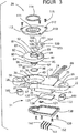
Eine erste Ausführungsform einer Drehlagesensoranordnung
Das Gehäuse
Das Gehäuse
Der Rotorhohlraum
Der Rotorhohlraum
Der Sensorhohlraum
Die Seitenwand
Zwei ovale Öffnungen oder Durchgangslöcher
Der Verbinderabschnitt oder das Gehäuse
Ein grundsätzlich runder Rotor
Ein erster zylindrischer Kragen
Der Kragen
Eine außermittige oder außerhalb der Welle oder außerhalb der Achse liegende Magnetausnehmung oder Tasche
Eine Umgangsausnehmung
Die Bohrung
Das rechteckige Ende
Wie in
Der Magnet
Der Rotor
Ein Sensor
Mehrere L-förmige, elektrisch leitende Metallanschlüsse
Eine weitere Abdeckplatte
Die Drehlagesensor-Anordnung
Wie in den
Der Sensor
Die
Spezieller erzeugt der Magnet
Bei dem Wellen- und Magnet-Drehwinkel oder -Lagewinkel von null Grad (
Bei einem Wellen- oder Magnet-Drehwinkel oder -Lagewinkel von fünfundvierzig Grad (
Bei einem Wellen- oder Magnet-Drehwinkel oder -Lagewinkel von neunzig Grad (
Die vorliegende Erfindung hat mehrere Vorteile. Die Verwendung einer mittigen Bohrung
Zusätzlich ermöglicht die Montage des Rotors
Die Verwendung des Hall-Effekt-Sensors in Form des integrierten Schaltkreises MLX90316 reduziert oder eliminiert ferner die Notwendigkeit einer Elektronik für die Temperaturkompensation, weil das MLX90316-Bauteil die Richtung der Magnetfeldvektoren in orthogonalen Achsen misst und diese Information zur Berechnung der Lage verwendet.The use of the MLX90316 integrated-circuit Hall-effect sensor further reduces or eliminates the need for temperature compensation electronics because the MLX90316 component measures the direction of the magnetic field vectors in orthogonal axes and uses this information to calculate the location.
Die Halbkreis- oder Mondform des Magneten
Die
Das Gehäuse
Eine kreisförmige Öffnung
Ein abgewinkelter Montageflansch oder Bügel
Ein hohler Verbinderabschnitt
Der Rotor
Das Magnetgehäuse
Das Magnetgehäuse
Der Magnet
Das Magnetgehäuse
Erfindungsgemäß verhindert die Form und der flexible Aufbau und die Konfiguration des Magnetgehäuses
Die gekrümmte Form des Magnetgehäuses
Die gedruckte Schaltungsplattenanordnung
Obwohl dies nicht im Einzelnen gezeigt oder beschrieben ist, wird man verstehen, dass die gedruckte Schaltungsplattenanordnung
Der Rotor
Die Unterseite
Die Endanschlagsflächen oder Wände
Eine Abdeckplatte
Die Platte
Obwohl dies hier nicht im einzelnen gezeigt oder beschrieben ist, wird man verstehen, dass eine Welle, die der zuvor in Bezug auf den Drehlagesensor
Obwohl dies nicht mit weiteren Einzelheiten beschrieben ist, wird man ferner verstehen, dass die Sensoranordnung
Insbesondere gilt, dass dann, wenn die Welle
Der Sensor
Die
Spezieller erzeugt der Magnet
Bei dem Dreh- oder Lagewinkel der Welle und des Magneten von null Grad (
Bei einem Dreh- oder Lagewinkel der Welle oder des Magneten von fünfundvierzig Grad (
Bei einem Dreh- oder Lagewinkel der Welle oder des Magneten von neunzig Grad (
Während die Erfindung mit Bezug auf zwei Ausführungsformen offenbart wurde, wird der Fachmann verstehen, dass Änderungen in der Form und den Einzelheiten vorgenommen werden können, ohne den Bereich der Erfindung zu verlassen. Die beschriebenen Ausführungen sind in jeder Hinsicht nur als Erläuterung, nicht als beschränkend zu verstehen. Der Bereich der Erfindung wird daher durch die folgenden Ansprüche und nicht durch die vorgehende Beschreibung angegeben. Alle Änderungen, die innerhalb des Wortsinns und der Äquivalenz der Ansprüche liegen, sollen von diesem Bereich umfasst sein.While the invention has been disclosed with reference to two embodiments, it will be understood by those skilled in the art that changes in form and details may be made without departing from the scope of the invention. The described embodiments are to be understood in all respects only as an explanation, not as limiting. The scope of the invention is, therefore, indicated by the following claims rather than by the foregoing description. All changes which are within the literal meaning and equivalency of the claims are intended to be embraced by this scope.
Claims (11)
Applications Claiming Priority (3)
| Application Number | Priority Date | Filing Date | Title |
|---|---|---|---|
| US20775509P | 2009-02-17 | 2009-02-17 | |
| US61/207,755 | 2009-02-17 | ||
| PCT/US2010/024250 WO2010096365A1 (en) | 2009-02-17 | 2010-02-16 | Rotary position sensor |
Publications (2)
| Publication Number | Publication Date |
|---|---|
| DE112010000835T5 DE112010000835T5 (en) | 2012-12-06 |
| DE112010000835B4 true DE112010000835B4 (en) | 2014-05-15 |
Family
ID=42124368
Family Applications (1)
| Application Number | Title | Priority Date | Filing Date |
|---|---|---|---|
| DE112010000835.3T Expired - Fee Related DE112010000835B4 (en) | 2009-02-17 | 2010-02-16 | Rotary position sensor |
Country Status (6)
| Country | Link |
|---|---|
| US (3) | US8450999B2 (en) |
| JP (2) | JP5409814B2 (en) |
| KR (1) | KR20110121706A (en) |
| CN (1) | CN102326053B (en) |
| DE (1) | DE112010000835B4 (en) |
| WO (1) | WO2010096365A1 (en) |
Families Citing this family (29)
| Publication number | Priority date | Publication date | Assignee | Title |
|---|---|---|---|---|
| JP5409814B2 (en) * | 2009-02-17 | 2014-02-05 | シーティーエス・コーポレーション | Rotary position sensor |
| WO2011060414A1 (en) | 2009-11-16 | 2011-05-19 | Cts Corporation | Non-contacting sensor assembly |
| WO2011115942A1 (en) * | 2010-03-17 | 2011-09-22 | Illinois Tool Works Inc. | Transmission gear position sensor using printed circuit element |
| FR2961284B1 (en) * | 2010-06-09 | 2013-04-19 | Ksb Sas | POSITION SENSOR VALVE |
| US9435630B2 (en) * | 2010-12-08 | 2016-09-06 | Cts Corporation | Actuator and linear position sensor assembly |
| US9513103B2 (en) * | 2011-04-19 | 2016-12-06 | Ford Global Technologies, Llc | Hitch angle sensor assembly |
| CN103717857B (en) * | 2011-08-08 | 2016-08-17 | 胡斯华纳有限公司 | Magnet holder in throttle valve position sensor, the magnet holder in the level sensor of angle and their manufacture method |
| US8720414B2 (en) * | 2011-12-22 | 2014-05-13 | Continental Automotive Systems, Inc. | Throttle position sensor assembly |
| KR20230116962A (en) | 2013-11-13 | 2023-08-04 | 브룩스 오토메이션 인코퍼레이티드 | Method and apparatus for brushless electrical machine control |
| KR20230034417A (en) | 2013-11-13 | 2023-03-09 | 브룩스 오토메이션 인코퍼레이티드 | Sealed robot drive |
| KR102665385B1 (en) | 2013-11-13 | 2024-05-13 | 브룩스 오토메이션 인코퍼레이티드 | Sealed switched reluctance motor |
| TWI695447B (en) | 2013-11-13 | 2020-06-01 | 布魯克斯自動機械公司 | Transport apparatus |
| DE102014200365A1 (en) * | 2013-11-26 | 2015-05-28 | Continental Teves Ag & Co. Ohg | Sensor arrangement and magnetization device and use of the sensor arrangement in a motor vehicle control unit |
| DE102015103972A1 (en) * | 2014-04-02 | 2015-10-08 | Ford Global Technologies, Llc | Joint angle sensor arrangement |
| JP6371114B2 (en) * | 2014-05-20 | 2018-08-08 | 愛三工業株式会社 | Rotation angle detector |
| DE102014213869A1 (en) * | 2014-07-16 | 2016-01-21 | Continental Automotive Gmbh | Sensor device for determining a displacement of a shaft |
| EP3018055B1 (en) * | 2014-11-06 | 2018-06-27 | Goodrich Actuation Systems SAS | Flight control surface actuation system with connecting rod |
| US9718525B1 (en) * | 2015-01-09 | 2017-08-01 | Brp Us Inc. | Steering position sensing system for a marine engine |
| CN105518981B (en) | 2015-03-11 | 2018-03-27 | 深圳市大疆灵眸科技有限公司 | Angle sensing device further and the head using the angle sensing device further |
| WO2018053794A1 (en) * | 2016-09-23 | 2018-03-29 | Hamlin Electronics (Suzhou) Co., Ltd. | Rotary position sensor with dual magnet arrangement |
| CN109891186B (en) * | 2016-09-23 | 2022-02-01 | 哈姆林电子(苏州)有限公司 | Integrated double-rotation position sensor |
| AT519455B1 (en) * | 2016-10-27 | 2018-07-15 | Melecs Ews Gmbh | Sensor arrangement with at least one magnetic sensor |
| EP3707477B1 (en) * | 2017-11-07 | 2023-07-05 | CTS Corporation | Rotary position sensor assembly including switch and patterned magnet |
| FR3081396B1 (en) * | 2018-05-25 | 2020-07-03 | Faurecia Sieges D'automobile | ARTICULATION ASSEMBLY INCLUDING A TILT SENSOR |
| SE542616C2 (en) * | 2018-09-27 | 2020-06-16 | Leine & Linde Ab | Rotary encoder and method for manufacturing a rotary encoder |
| CN109737865A (en) * | 2019-01-25 | 2019-05-10 | 百年旭康医疗器械有限公司 | A kind of universal single dof mobility brace angle measurement unit and its application method |
| DE102021105566A1 (en) * | 2020-03-24 | 2021-09-30 | Honeywell International Inc. | ROTARY ENCODER |
| CN112857205B (en) * | 2021-04-09 | 2022-07-22 | 中国石油大学(华东) | Surface crack monitoring method for rotating electromagnetic field structure |
| US11442074B1 (en) * | 2021-04-20 | 2022-09-13 | Infineon Technologies Ag | Offset-reduced zero-gauss-magnet with polepiece for differential, twist-insensitive magnetic speed sensors |
Citations (5)
| Publication number | Priority date | Publication date | Assignee | Title |
|---|---|---|---|---|
| US4125821A (en) * | 1977-08-05 | 1978-11-14 | Denki Onkyo Company, Limited | Potentiometer providing a non-linear output |
| US5270645A (en) * | 1991-08-30 | 1993-12-14 | Nartron Corporation | Linear-output, temperature-stable rotational sensor including magnetic field responsive device disposed within a cavity of a flux concentrator |
| JPH08241806A (en) * | 1995-03-02 | 1996-09-17 | Nippondenso Co Ltd | Non-contact position sensor |
| EP1308692A1 (en) * | 2001-10-31 | 2003-05-07 | Tyco Electronics AMP K.K. | Rotation angle sensor |
| US20060017430A1 (en) * | 2004-07-20 | 2006-01-26 | Honeywell International, Inc. | Offset magnet rotary position sensor |
Family Cites Families (147)
| Publication number | Priority date | Publication date | Assignee | Title |
|---|---|---|---|---|
| US1296650A (en) * | 1918-11-06 | 1919-03-11 | David F Graham | Ball-bearing. |
| US2935714A (en) * | 1958-04-25 | 1960-05-03 | Chicago Telephone Supply Corp | Variable resistor with vernier control |
| US3047751A (en) * | 1959-05-04 | 1962-07-31 | Molectronics Corp | Motor-potentiometer assembly |
| US3097316A (en) * | 1959-12-31 | 1963-07-09 | Cts Corp | Impulse motor |
| US3521095A (en) * | 1968-07-01 | 1970-07-21 | Dale Electronics | Motorized potentiometer |
| US3610714A (en) | 1970-01-02 | 1971-10-05 | Albert M De Gaeta | Ball bearing |
| GB1368788A (en) * | 1970-12-28 | 1974-10-02 | Gujitsu Ltd | Electric stepping motor |
| SE350708B (en) * | 1971-03-15 | 1972-11-06 | Alfa Laval Ab | |
| DE2212621C3 (en) | 1972-03-16 | 1982-05-13 | Schwarzbich, Jörg, 4800 Bielefeld | Axial cylindrical roller bearings |
| US3971963A (en) * | 1973-09-11 | 1976-07-27 | Hiroshi Koike | Electomagnetic rotary motion device and exposure control device using the same |
| US4006375A (en) * | 1974-02-14 | 1977-02-01 | Cambridge Thermionic Corporation | Stepping motor |
| DE2518129A1 (en) * | 1975-04-24 | 1976-11-04 | Schaeffler Ohg Industriewerk | THIN WALLED RING OR. RACING PLATE FOR A BALL BEARING, BALL BEARING MANUFACTURED FROM IT, AND THE METHOD AND DEVICE FOR THEIR PRODUCTION |
| DE2654755A1 (en) * | 1976-12-03 | 1978-06-08 | Bosch Gmbh Robert | INDUCTIVE PULSE GENERATOR WITH SPEED INDEPENDENT PULSE AMPLITUDE |
| DE2705623A1 (en) * | 1977-02-10 | 1978-08-17 | Nihon Radiator Co | ENGINE WITH PRINTED WRAP |
| US4334352A (en) * | 1978-04-24 | 1982-06-15 | Cts Corporation | Method of making a variable resistance control |
| DE2831314C3 (en) * | 1978-07-17 | 1982-03-11 | Keiper Automobiltechnik Gmbh & Co Kg, 5630 Remscheid | Adjustment device for vehicle seats, in particular vehicle seats |
| US4228378A (en) | 1979-05-21 | 1980-10-14 | Humbert Marcel E | Wire wound disc armature for dynamoelectric machine |
| US4355293A (en) | 1979-10-22 | 1982-10-19 | The Bendix Corporation | Electrical resistance apparatus having integral shorting protection |
| GB2062875B (en) | 1979-11-03 | 1983-08-10 | Lucas Industries Ltd | Rotation and axial displacemetn transducers |
| JPS5672311U (en) | 1979-11-06 | 1981-06-13 | ||
| US5110221A (en) * | 1981-04-20 | 1992-05-05 | Kamatics Corporation | Self-aligning track roller |
| US4430634A (en) * | 1982-01-18 | 1984-02-07 | Cts Corporation | Rotary potentiometer with molded terminal package |
| DE3209203A1 (en) * | 1982-03-13 | 1983-09-15 | Skf Kugellagerfabriken Gmbh, 8720 Schweinfurt | SELF-ADJUSTING STORAGE |
| US4435691A (en) * | 1982-03-22 | 1984-03-06 | Cts Corporation | Dual track resistor element having nonlinear output |
| US4529933A (en) * | 1982-04-26 | 1985-07-16 | Cts Corporation | Speed sensor and method for producing same |
| US4503417A (en) * | 1982-06-14 | 1985-03-05 | Cts Corporation | Leak proof position sensor with permanent magnet shaft |
| US4575929A (en) * | 1982-11-24 | 1986-03-18 | Cts Corporation | Method for making a precision linear potentiometer sensor |
| US4479107A (en) | 1982-11-24 | 1984-10-23 | Cts Corporation | Precision linear potentiometer sensor |
| US4616504A (en) | 1983-05-03 | 1986-10-14 | Duncan Electronics | Throttle position sensor |
| US4645430A (en) * | 1984-04-25 | 1987-02-24 | Facet Enterprises, Inc. | Wet motor gerotor fuel pump with self-aligning bearing |
| US4588314A (en) * | 1984-08-15 | 1986-05-13 | Joseph Anscher | Bearing cage |
| US4541744A (en) * | 1984-11-15 | 1985-09-17 | General Motors Coporation | Unitized bearing assembly with moldable race members and labryinth seal |
| GB8500396D0 (en) | 1985-01-08 | 1985-02-13 | Skf Uk Ltd | Preventing movement of article |
| DE3511872A1 (en) * | 1985-04-01 | 1986-10-02 | BSG-Schalttechnik GmbH & Co KG, 7460 Balingen | TURNING OR SLIDING POTENTIOMETER (STEP SWITCH) AND METHOD FOR THE PRODUCTION THEREOF |
| JPS61279742A (en) * | 1985-06-05 | 1986-12-10 | Nippon Denso Co Ltd | Throttle valve opening detector for vehicles |
| JPH0526961Y2 (en) | 1985-12-09 | 1993-07-08 | ||
| CH665069A5 (en) * | 1985-12-11 | 1988-04-15 | Portescap | SINGLE-STAGE DI- OR TETRAPHASE SYNCHRONOUS ELECTRIC MOTOR. |
| US4854437A (en) * | 1986-06-25 | 1989-08-08 | Aetna Bearing Company | Radially adjustable clutch release bearing assembly |
| US4951796A (en) * | 1986-06-25 | 1990-08-28 | Aetna Bearing Company | Radially adjustable clutch release bearing assembly |
| JPS6335158A (en) | 1986-07-25 | 1988-02-15 | Shicoh Eng Co Ltd | Single-phase brushless motor |
| US4708497A (en) | 1986-11-03 | 1987-11-24 | General Motors Corporation | Unitized bearing with free molded seals |
| KR920007896Y1 (en) | 1986-12-26 | 1992-10-22 | 미쓰비시전기 주식회사 | Apparatus for detecting throttle valve opening of engine |
| JPS63113476U (en) * | 1987-01-14 | 1988-07-21 | ||
| DE3850164T2 (en) * | 1987-04-03 | 1994-09-22 | Hitachi Ltd | Method and device for detecting the angle of rotation. |
| US4722617A (en) * | 1987-07-17 | 1988-02-02 | The Torrington Company | Ball bearing assembly |
| US4822183A (en) * | 1988-09-06 | 1989-04-18 | General Motors Corporation | Thrust ball bearing with improved sealing |
| AU634735B2 (en) | 1988-12-26 | 1993-03-04 | Wing Highcera Co. Ltd. | Ceramic bearing and manufacturing method |
| JPH02141810U (en) * | 1989-01-05 | 1990-11-29 | ||
| FR2648632B1 (en) * | 1989-06-16 | 1991-10-04 | Moving Magnet Tech | LOW SIZE SINGLE PHASE ELECTROMAGNETIC ACTUATOR |
| US5023599A (en) * | 1989-06-22 | 1991-06-11 | Cts Corporation | Throttle position sensor advanced brake light device |
| JPH0727609Y2 (en) * | 1989-07-03 | 1995-06-21 | アルプス電気株式会社 | Variable resistor |
| US4985669A (en) * | 1989-07-13 | 1991-01-15 | Tri-Tech Inc. | Motor feedback system |
| US5184040A (en) * | 1989-09-04 | 1993-02-02 | Lim Jong H | Electric power generators having like numbers of magnets and coils |
| JP2796372B2 (en) | 1989-09-20 | 1998-09-10 | 株式会社日立製作所 | Throttle sensor |
| US4973866A (en) | 1989-09-26 | 1990-11-27 | North American Philips Corporation | Variable angle stepper motor |
| JPH0756598Y2 (en) | 1989-09-27 | 1995-12-25 | 松下電器産業株式会社 | Electric motor with gear reducer |
| DE3932146A1 (en) * | 1989-09-27 | 1991-04-04 | Stabilus Gmbh | AXIAL BEARING FOR THE COLUMN OF A HYDROPNEUMATIC SEAT FURNITURE ADJUSTMENT |
| JPH03165214A (en) * | 1989-11-24 | 1991-07-17 | Yamaha Corp | Angle sensor |
| DE4003052A1 (en) * | 1990-02-02 | 1991-08-08 | Schaeffler Waelzlager Kg | RADIAL BALL BEARING |
| DE4028931A1 (en) | 1990-09-12 | 1992-03-19 | Bosch Gmbh Robert | ROTARY ENCODER |
| FR2670286B1 (en) * | 1990-12-05 | 1993-03-26 | Moving Magnet Tech | MAGNETIC POSITION AND SPEED SENSOR WITH HALL PROBE. |
| US5512871A (en) * | 1990-12-17 | 1996-04-30 | Moving Magnet Technologies S.A. | Rotatable single-phase electromagnetic actuator |
| JP3273052B2 (en) | 1991-01-29 | 2002-04-08 | シーティーエス・コーポレーション | Electronic circuit packaged with position sensor |
| US5321980A (en) * | 1991-05-10 | 1994-06-21 | Williams Controls, Inc. | Integrated throttle position sensor with independent position validation sensor |
| US5133321A (en) * | 1991-05-10 | 1992-07-28 | Hering Charles A | Integrated throttle control and idle validation sensor |
| FR2688105B1 (en) * | 1992-02-28 | 1994-05-06 | Moving Magnet Technologies Sa | ELECTROMAGNETIC ROTARY ACTUATOR SINGLE-PHASE RACE BETWEEN 60 AND 120 DEGREES. |
| JPH05308768A (en) * | 1992-04-28 | 1993-11-19 | Minebea Co Ltd | Stator yoke for stepping motor |
| US5332965A (en) * | 1992-06-22 | 1994-07-26 | Durakool Incorporated | Contactless linear angular position sensor having an adjustable flux concentrator for sensitivity adjustment and temperature compensation |
| JP2959295B2 (en) | 1992-09-22 | 1999-10-06 | 松下電器産業株式会社 | Motor driven variable resistor |
| US5309134A (en) * | 1992-10-15 | 1994-05-03 | Cts Corporation | Sensor with sloped termination for reduced element bend |
| DE4240615C2 (en) * | 1992-12-03 | 2001-11-15 | Bosch Gmbh Robert | Position transmitter |
| US5416295A (en) * | 1992-12-18 | 1995-05-16 | Cts Corporation | Combined pedal force switch and position sensor |
| US5385068A (en) * | 1992-12-18 | 1995-01-31 | Cts Corporation | Electronic accelerator pedal assembly with pedal force sensor |
| JP2591055Y2 (en) * | 1992-12-22 | 1999-02-24 | 日本精工株式会社 | Sealed ball bearings |
| US5460035A (en) * | 1993-06-23 | 1995-10-24 | Cts Corporation | Bearing free spring free throttle position sensor |
| US5417500A (en) * | 1993-09-13 | 1995-05-23 | Reliance Electric Industrial Company | Bearing assembly utilizing improved clamping collar |
| US5539373A (en) * | 1993-11-08 | 1996-07-23 | Cts Corporation | Rotor structure for a position sensor |
| DE69324603T2 (en) * | 1993-11-30 | 1999-09-16 | Citizen Watch Co Ltd | MICROMOTOR |
| US6037696A (en) * | 1993-12-29 | 2000-03-14 | Samot Engineering (1992) Ltd. | Permanent magnet axial air gap electric machine |
| US5415144A (en) * | 1994-01-14 | 1995-05-16 | Robertshaw Controls Company | Throttle position validation method and apparatus |
| US5757179A (en) * | 1994-03-04 | 1998-05-26 | Cts Corporation | Position sensor with improved magnetic circuit |
| US5798639A (en) | 1994-03-04 | 1998-08-25 | Cts Corporation | Rotary position sensor with improved bearing tolerance |
| CA2143811A1 (en) * | 1994-03-04 | 1995-09-05 | Jeffrey L. Mccurley | Field strength position sensor with improved bearing tolerance in reduced space |
| JP3232925B2 (en) * | 1994-03-10 | 2001-11-26 | トヨタ自動車株式会社 | Intake air amount calculation device for internal combustion engine |
| US5551236A (en) | 1994-05-02 | 1996-09-03 | Dresser Industries, Inc. | Turbocharger control management system |
| US5955881A (en) * | 1994-10-18 | 1999-09-21 | Cts Corporation | Linkage position sensor having a magnet with two ramped sections for providing variable magnetic field |
| KR0155782B1 (en) | 1994-12-02 | 1999-03-20 | 김광호 | Driving circuit protection apparatus & method of a d.c. brushless motor compressor |
| JP3259560B2 (en) | 1995-01-06 | 2002-02-25 | 日本精工株式会社 | Ball bearing |
| DE19525510B4 (en) * | 1995-07-13 | 2008-05-08 | Robert Bosch Gmbh | Throttle actuator |
| JPH0968403A (en) | 1995-08-31 | 1997-03-11 | Denso Corp | Opening sensor for throttle valve |
| WO1997009659A1 (en) | 1995-09-05 | 1997-03-13 | Cts Corporation | Rotary position sensor with insert molded coil winding |
| US5613571A (en) * | 1995-09-26 | 1997-03-25 | Harley-Davidson, Inc. | Rotational speed/tip sensor |
| JP3052304B2 (en) * | 1995-11-17 | 2000-06-12 | 日本精機株式会社 | Stepping motor |
| US5811968A (en) * | 1996-01-06 | 1998-09-22 | Unisia Jecs Corporation | Rotation angle sensor |
| US5889400A (en) * | 1996-03-08 | 1999-03-30 | Unisia Jecs Corporation | Sensor arranged for detecting angular displacement and direction of valve axle |
| US5831356A (en) | 1996-04-08 | 1998-11-03 | Canon Kabushiki Kaisha | Compact cylindrical stepping motor and advancing device |
| JPH10110345A (en) * | 1996-09-23 | 1998-04-28 | Sunkyong Ind Ltd | Production of mixed yarn having different shrinkage and apparatus therefor |
| US6175233B1 (en) * | 1996-10-18 | 2001-01-16 | Cts Corporation | Two axis position sensor using sloped magnets to generate a variable magnetic field and hall effect sensors to detect the variable magnetic field |
| US5731649A (en) * | 1996-12-27 | 1998-03-24 | Caama+E,Otl N+Ee O; Ramon A. | Electric motor or generator |
| US5828290A (en) | 1997-08-22 | 1998-10-27 | Cts Corporation | Modular position sensor |
| US5810484A (en) * | 1997-08-27 | 1998-09-22 | Cts Corporation | Bearing for slanted surfaces |
| US5828151A (en) | 1997-08-27 | 1998-10-27 | Cts Corporation | Self aligning actuator with low bearing wear |
| FI108887B (en) * | 1998-01-23 | 2002-04-15 | Metso Paper Automation Oy | Operating device |
| FI104463B (en) * | 1998-03-02 | 2000-02-15 | Polar Electro Oy | Metering system |
| US6057682A (en) * | 1998-04-17 | 2000-05-02 | Cts Corporation | Dual rotational and linear position sensor |
| US6179268B1 (en) * | 1998-04-21 | 2001-01-30 | Saturn Electronics & Engineering, Inc. | Proportional variable force solenoid control valve with segmented permanent magnet |
| US6472865B1 (en) * | 1998-05-08 | 2002-10-29 | Wabash Technologies, Inc. | Magnetic rotational position sensor having dual magnetic flux sensor capabilities |
| US6137288A (en) * | 1998-05-08 | 2000-10-24 | Luetzow; Robert Herman | Magnetic rotational position sensor |
| US6188216B1 (en) * | 1998-05-18 | 2001-02-13 | Cts Corporation | Low profile non-contacting position sensor |
| US6124709A (en) | 1998-06-05 | 2000-09-26 | Cts Corporation | Magnetic position sensor having a variable width magnet mounted into a rotating disk and a hall effect sensor |
| US6198182B1 (en) * | 1998-09-02 | 2001-03-06 | Cts Corporation | Two-phase stepper motor having two disk stators with salient poles positioned on either side of two disk rotors |
| US5982058A (en) | 1998-09-02 | 1999-11-09 | Cts Corporation | Two-phase stepper motor |
| JP3637217B2 (en) * | 1998-10-13 | 2005-04-13 | 株式会社緑測器 | Small rotation angle sensor |
| US5963124A (en) | 1998-11-30 | 1999-10-05 | Cts Corporation | Cover mounted position sensor |
| US6211668B1 (en) * | 1998-12-09 | 2001-04-03 | Cts | Magnetic position sensor having opposed tapered magnets |
| US6304078B1 (en) | 1998-12-09 | 2001-10-16 | Cts Corporation | Linear position sensor |
| US6018992A (en) * | 1999-01-18 | 2000-02-01 | Cts Corporation | Position sensor having termination clip |
| US6031448A (en) * | 1999-02-05 | 2000-02-29 | Cts Corporation | Modular position sensor |
| US6288534B1 (en) | 1999-02-10 | 2001-09-11 | Cts Corporation | Non-contacting throttle valve position sensor |
| US6040756A (en) * | 1999-02-16 | 2000-03-21 | Cts Corproation | Compact potentiometer |
| US6323641B1 (en) | 1999-05-13 | 2001-11-27 | Cts Corporation | Non-contacting position sensor with helical flux linkage |
| US6222359B1 (en) * | 1999-06-18 | 2001-04-24 | Cts Corporation | Non-contacting position sensor using radial bipolar tapered magnets |
| US6639508B1 (en) | 1999-09-22 | 2003-10-28 | Aptek Williams, Inc. | Electrical switch device and process for manufacturing same |
| KR100453328B1 (en) * | 1999-12-14 | 2004-10-21 | 마쯔시다덴기산교 가부시키가이샤 | Noncontact position sensor |
| DE10001047B4 (en) | 2000-01-13 | 2011-01-05 | Ksb Ag | Device for determining the axial rotor position in hermetically sealed drives |
| US6556005B1 (en) * | 2000-01-27 | 2003-04-29 | Goodrich Avionics Systems, Inc. | Magnetic encoder apparatus capable of resolving axial and rotational displacements |
| US6323643B1 (en) | 2000-03-08 | 2001-11-27 | Cts Corporation | Rotary position sensor having a semi-parabolic magnet |
| US6367337B1 (en) * | 2000-05-03 | 2002-04-09 | Cts Corporation | Non-contacting sensor for measuring relative displacement between two rotating shafts |
| JP3751509B2 (en) | 2000-07-25 | 2006-03-01 | アルプス電気株式会社 | Rotation type sensor |
| JP2002181509A (en) * | 2000-12-12 | 2002-06-26 | Yazaki Corp | Position detector |
| US6515472B2 (en) * | 2001-05-25 | 2003-02-04 | Cts Corporation | Transmission selector sensor assembly package for integration into transmission assembly |
| ITTO20010730A1 (en) * | 2001-07-24 | 2003-01-24 | Campagnolo Srl | ANGULAR SIZE TRANSDUCER. |
| JP4191940B2 (en) | 2002-03-12 | 2008-12-03 | アルプス電気株式会社 | Rotary position sensor |
| WO2003098147A1 (en) | 2002-05-15 | 2003-11-27 | American Electronic Components, Inc. | Through the hole rotary position sensor |
| US6798193B2 (en) * | 2002-08-14 | 2004-09-28 | Honeywell International Inc. | Calibrated, low-profile magnetic sensor |
| DE20214511U1 (en) | 2002-09-19 | 2004-02-19 | Kiekert Ag | Electric motor rotation counter has magnet sensor and Hall effect detector mounted on hollow motor end cover including motor connections |
| JP4201654B2 (en) * | 2003-06-18 | 2008-12-24 | 栄通信工業株式会社 | Magnetic potentiometer |
| US6992478B2 (en) * | 2003-12-22 | 2006-01-31 | Cts Corporation | Combination hall effect position sensor and switch |
| US20070008063A1 (en) * | 2004-08-13 | 2007-01-11 | Cts Corporation | Rotary actuator with non-contacting position sensor |
| US7439732B2 (en) | 2004-09-24 | 2008-10-21 | Stoneridge Control Devices, Inc. | Rotary position sensor |
| JP2006214873A (en) * | 2005-02-03 | 2006-08-17 | Mitsumi Electric Co Ltd | Rotation detector and mounting structure |
| DE102005013442A1 (en) | 2005-03-23 | 2006-09-28 | Robert Bosch Gmbh | Accelerator pedal module with magnetic sensor |
| US7230419B2 (en) | 2005-06-03 | 2007-06-12 | Delphi Technologies, Inc. | Rotary position sensor |
| FR2898189B1 (en) | 2006-03-02 | 2008-10-17 | Moving Magnet Tech | POSITION SENSOR WITH VARIABLE MAGNET DIRECTION AND METHOD OF MAKING SAME |
| JP2010520458A (en) * | 2007-02-28 | 2010-06-10 | コンティネンタル オートモーティブ システムズ ユーエス, インコーポレイティッド | Linear position sensor |
| WO2008112100A2 (en) | 2007-03-07 | 2008-09-18 | Cts Corporation | Rotary position sensor |
| JP5409814B2 (en) * | 2009-02-17 | 2014-02-05 | シーティーエス・コーポレーション | Rotary position sensor |
-
2010
- 2010-02-16 JP JP2011550305A patent/JP5409814B2/en not_active Expired - Fee Related
- 2010-02-16 KR KR1020117021131A patent/KR20110121706A/en not_active Application Discontinuation
- 2010-02-16 US US12/706,026 patent/US8450999B2/en not_active Expired - Fee Related
- 2010-02-16 WO PCT/US2010/024250 patent/WO2010096365A1/en active Application Filing
- 2010-02-16 CN CN201080008126.3A patent/CN102326053B/en not_active Expired - Fee Related
- 2010-02-16 DE DE112010000835.3T patent/DE112010000835B4/en not_active Expired - Fee Related
-
2013
- 2013-05-20 US US13/897,487 patent/US8692544B2/en active Active
- 2013-11-05 JP JP2013229446A patent/JP2014055966A/en active Pending
-
2014
- 2014-02-12 US US14/178,319 patent/US9297637B2/en not_active Expired - Fee Related
Patent Citations (5)
| Publication number | Priority date | Publication date | Assignee | Title |
|---|---|---|---|---|
| US4125821A (en) * | 1977-08-05 | 1978-11-14 | Denki Onkyo Company, Limited | Potentiometer providing a non-linear output |
| US5270645A (en) * | 1991-08-30 | 1993-12-14 | Nartron Corporation | Linear-output, temperature-stable rotational sensor including magnetic field responsive device disposed within a cavity of a flux concentrator |
| JPH08241806A (en) * | 1995-03-02 | 1996-09-17 | Nippondenso Co Ltd | Non-contact position sensor |
| EP1308692A1 (en) * | 2001-10-31 | 2003-05-07 | Tyco Electronics AMP K.K. | Rotation angle sensor |
| US20060017430A1 (en) * | 2004-07-20 | 2006-01-26 | Honeywell International, Inc. | Offset magnet rotary position sensor |
Also Published As
| Publication number | Publication date |
|---|---|
| JP2014055966A (en) | 2014-03-27 |
| KR20110121706A (en) | 2011-11-08 |
| CN102326053A (en) | 2012-01-18 |
| US20140152296A1 (en) | 2014-06-05 |
| US9297637B2 (en) | 2016-03-29 |
| US8450999B2 (en) | 2013-05-28 |
| DE112010000835T5 (en) | 2012-12-06 |
| US8692544B2 (en) | 2014-04-08 |
| WO2010096365A1 (en) | 2010-08-26 |
| CN102326053B (en) | 2015-02-18 |
| US20100207616A1 (en) | 2010-08-19 |
| US20130241539A1 (en) | 2013-09-19 |
| JP5409814B2 (en) | 2014-02-05 |
| JP2012518172A (en) | 2012-08-09 |
Similar Documents
| Publication | Publication Date | Title |
|---|---|---|
| DE112010000835B4 (en) | Rotary position sensor | |
| DE69906917T2 (en) | Non-contact position measuring device with tapered bipolar magnets | |
| DE112010004761T5 (en) | Drive and sensor arrangement | |
| EP2743662B1 (en) | Device with a torque sensor device and optionally a steering angle sensor apparatus for a motor vehicle | |
| EP2965043B1 (en) | Magnetic linear or rotary encoder | |
| DE102007034099B4 (en) | Device for the contactless detection of the relative positions of two parts that can be moved to one another | |
| EP2564164B1 (en) | Magnetic length measuring system, length measuring method and method for producing a magnetic length measuring system | |
| DE102010033769A1 (en) | Device with a torque sensor and a rotation angle sensor | |
| DE112008003309T5 (en) | Linear position sensor | |
| DE202007011837U1 (en) | angle sensor | |
| EP2620752A2 (en) | Magnetic field sensor | |
| DE10139154B4 (en) | Angular position sensor | |
| DE102014011245B3 (en) | Magnetic field measuring device | |
| DE102010000671A1 (en) | Rotation angle sensor | |
| DE112010004410T5 (en) | Non-contact sensor arrangement | |
| DE102007016133A1 (en) | Measuring device for non-contact detection of a rotation angle with arranged in a recess of the magnet magnetically sensitive element | |
| EP3118585B1 (en) | Magnetic field measuring device | |
| DE102014008173A1 (en) | Magnetic field measuring device | |
| DE102005005111A1 (en) | Rotational encoder for measurement of angular position and velocity has a magnetic element and magnetic sensor element for velocity determination that are mounted on opposite sides of a partial disk for position determination | |
| DE102014207139A1 (en) | Measuring device for a contactless rotation angle detection | |
| DE102013103445A1 (en) | Magnetic linear or rotary encoder | |
| DE102006036746B4 (en) | Position measuring device | |
| EP0836072B1 (en) | Rotation sensor | |
| DE19744673C2 (en) | Device for detecting the speed of a rotating component, in particular for a motor vehicle | |
| DE102007024867A1 (en) | Measuring device for non-contact detection of a rotation angle with radially polarized magnet |
Legal Events
| Date | Code | Title | Description |
|---|---|---|---|
| R016 | Response to examination communication | ||
| R012 | Request for examination validly filed |
Effective date: 20130306 |
|
| R016 | Response to examination communication | ||
| R016 | Response to examination communication | ||
| R018 | Grant decision by examination section/examining division | ||
| R130 | Divisional application to |
Ref document number: 112010006107 Country of ref document: DE Effective date: 20140224 |
|
| R020 | Patent grant now final | ||
| R020 | Patent grant now final |
Effective date: 20150217 |
|
| R119 | Application deemed withdrawn, or ip right lapsed, due to non-payment of renewal fee |