DE10357698A1 - Carrier for objects to be treated and method for producing such - Google Patents
Carrier for objects to be treated and method for producing such Download PDFInfo
- Publication number
- DE10357698A1 DE10357698A1 DE2003157698 DE10357698A DE10357698A1 DE 10357698 A1 DE10357698 A1 DE 10357698A1 DE 2003157698 DE2003157698 DE 2003157698 DE 10357698 A DE10357698 A DE 10357698A DE 10357698 A1 DE10357698 A1 DE 10357698A1
- Authority
- DE
- Germany
- Prior art keywords
- carrier
- fibers
- stabilized
- silicon carbide
- carbon
- Prior art date
- Legal status (The legal status is an assumption and is not a legal conclusion. Google has not performed a legal analysis and makes no representation as to the accuracy of the status listed.)
- Ceased
Links
Classifications
-
- H—ELECTRICITY
- H01—ELECTRIC ELEMENTS
- H01L—SEMICONDUCTOR DEVICES NOT COVERED BY CLASS H10
- H01L21/00—Processes or apparatus adapted for the manufacture or treatment of semiconductor or solid state devices or of parts thereof
- H01L21/67—Apparatus specially adapted for handling semiconductor or electric solid state devices during manufacture or treatment thereof; Apparatus specially adapted for handling wafers during manufacture or treatment of semiconductor or electric solid state devices or components ; Apparatus not specifically provided for elsewhere
- H01L21/683—Apparatus specially adapted for handling semiconductor or electric solid state devices during manufacture or treatment thereof; Apparatus specially adapted for handling wafers during manufacture or treatment of semiconductor or electric solid state devices or components ; Apparatus not specifically provided for elsewhere for supporting or gripping
- H01L21/687—Apparatus specially adapted for handling semiconductor or electric solid state devices during manufacture or treatment thereof; Apparatus specially adapted for handling wafers during manufacture or treatment of semiconductor or electric solid state devices or components ; Apparatus not specifically provided for elsewhere for supporting or gripping using mechanical means, e.g. chucks, clamps or pinches
- H01L21/68714—Apparatus specially adapted for handling semiconductor or electric solid state devices during manufacture or treatment thereof; Apparatus specially adapted for handling wafers during manufacture or treatment of semiconductor or electric solid state devices or components ; Apparatus not specifically provided for elsewhere for supporting or gripping using mechanical means, e.g. chucks, clamps or pinches the wafers being placed on a susceptor, stage or support
- H01L21/68757—Apparatus specially adapted for handling semiconductor or electric solid state devices during manufacture or treatment thereof; Apparatus specially adapted for handling wafers during manufacture or treatment of semiconductor or electric solid state devices or components ; Apparatus not specifically provided for elsewhere for supporting or gripping using mechanical means, e.g. chucks, clamps or pinches the wafers being placed on a susceptor, stage or support characterised by a coating or a hardness or a material
-
- Y—GENERAL TAGGING OF NEW TECHNOLOGICAL DEVELOPMENTS; GENERAL TAGGING OF CROSS-SECTIONAL TECHNOLOGIES SPANNING OVER SEVERAL SECTIONS OF THE IPC; TECHNICAL SUBJECTS COVERED BY FORMER USPC CROSS-REFERENCE ART COLLECTIONS [XRACs] AND DIGESTS
- Y10—TECHNICAL SUBJECTS COVERED BY FORMER USPC
- Y10T—TECHNICAL SUBJECTS COVERED BY FORMER US CLASSIFICATION
- Y10T428/00—Stock material or miscellaneous articles
- Y10T428/249921—Web or sheet containing structurally defined element or component
- Y10T428/249924—Noninterengaged fiber-containing paper-free web or sheet which is not of specified porosity
Landscapes
- Engineering & Computer Science (AREA)
- Physics & Mathematics (AREA)
- Condensed Matter Physics & Semiconductors (AREA)
- General Physics & Mathematics (AREA)
- Manufacturing & Machinery (AREA)
- Computer Hardware Design (AREA)
- Microelectronics & Electronic Packaging (AREA)
- Power Engineering (AREA)
- Chemical Vapour Deposition (AREA)
- Ceramic Products (AREA)
- Container, Conveyance, Adherence, Positioning, Of Wafer (AREA)
Abstract
Die Erfindung bezieht sich auf einen Träger (10) für einen Gegenstand (12), vorzugsweise Substrat eines Halbleiterbauelements wie Wafer, mit einer Aufnahme für den Gegenstand und unterhalb der Aufnahme sich entlang des von dieser aufgenommenen Gegenstandes vorhandenen Gasaustrittsöffnungen. Damit über die Gasaustrittsöffnungen wohl dosiert und fein verteilt ein gewünschtes Gas austreten kann, wird vorgeschlagen, dass der Träger (10) zumindest abschnittsweise aus einem Material aus stabilisierten Fasern (18, 20) mit einer die Gasaustrittsöffnungen bildenden Porosität besteht.The invention relates to a carrier (10) for an object (12), preferably a substrate of a semiconductor device such as wafers, with a receptacle for the object and below the receptacle along the gas outlet openings provided by this object. In order to ensure that a desired gas can be dispensed through the gas outlet openings in a well-dosed and finely distributed manner, it is proposed that the carrier (10) consist, at least in sections, of a material of stabilized fibers (18, 20) having a porosity forming the gas outlet openings.
Description
Die Erfindung bezieht sich auf einen Träger für zu behandelnden wie zu beschichtenden oder zu reinigenden insbesondere flächigen Gegenstand, vorzugsweise Substrat eines Halbleiterbauelements wie Wafer, mit einer Aufnahme für den Gegenstand und unterhalb der Aufnahme sich entlang des von dieser aufgenommenen Gegenstandes erstreckenden Gasaustrittsöffnungen. Ferner bezieht sich die Erfindung auf ein Verfahren zur Herstellung eines Trägers für zu behandelnden wie zu beschichtenden oder zu reinigenden insbesondere flächigen Gegenstand, vorzugsweise Substrat eines Halbleiterbauelements wie Wafer, wobei in dem Träger im Bereich unterhalb des von diesem aufgenommenen Gegenstandes Gasaustrittsöffnungen ausgebildet werden.The This invention relates to a carrier for treating as to be coated or to be cleaned in particular flat object, preferably Substrate of a semiconductor device such as wafers, with a receptacle for the Subject and below the picture itself along the of this absorbed object extending gas outlet openings. Furthermore, the invention relates to a process for the preparation a carrier for too in particular as to be coated or to be cleaned flat Object, preferably substrate of a semiconductor device such as Wafer, wherein in the carrier in the area below the object received by this gas outlet openings be formed.
Ein
entsprechender Träger
kann z.B. für
CVD-Prozesse benutzt werden. Dabei kann der durch die Gasaustrittsöffnungen
austretende Gasstrom sicherstellen, dass eine Selbstdotierung durch
Dotieratome, die den Gegenstand durchsetzen, unterbleibt, indem
das Gas diese wegführt
(siehe
Um
in einer Prozesskammer auch die Rückseite eines flachen Gegenstandes
zu reinigen, ist nach der
Ein
Suszeptor für
eine CVD-Anordnung weist nach der
Der vorliegenden Erfindung liegt das Problem zu Grunde, einen Träger der eingangs genannten Art sowie ein Verfahren zum Herstellen eines solchen so weiterzubilden, dass über die Gasaustrittsöffnungen wohl dosiert und fein verteilt ein gewünschtes Gas austreten kann. Gleichzeitig soll die Möglichkeit geschaffen werden, das Gas im gewünschten Umfang definiert zu erwärmen.Of the The present invention is based on the problem, a carrier of the aforementioned type and a method for producing a to develop such that over the gas outlet openings well dosed and finely distributed a desired gas can escape. At the same time the possibility be created, the gas defined to the extent desired heat.
Zur Lösung des Problems sieht die Erfindung im Wesentlichen vor, dass der Träger zumindest abschnittsweise aus einem Material aus stabilisierten Fasern mit einer die Gasaustrittsöffnungen bildenden Porosität besteht. Insbesondere umfasst der Träger ein aus Si- und/oder C-Fasern sich zusammensetzendes Gerüst, das durch Gasphaseninfiltration und/oder Flüssigkeitsimprägnierung stabilisiert ist. Die Struktur kann dabei aus Filz, Vlies und/oder Gewebelagen bestehen.to solution of the problem, the invention essentially provides that the carrier at least partially made of a material of stabilized fibers with one the gas outlet openings forming porosity consists. In particular, the carrier comprises one of Si and / or C fibers composing scaffolding, by gas phase infiltration and / or liquid impregnation is stabilized. The structure can be made of felt, fleece and / or Fabric layers exist.
Die Stabilisierung bzw. Versteifung der Fasern erfolgt durch chemische Gasphaseninfiltration (CVI) und/oder Imprägnierung mit flüssigen Substanzen. Hierdurch werden auf den Fasern Kohlenstoff- und/oder Siliziumkarbid-Schichten abgeschieden bzw. solche aus den Fasern ausgebildet. Die Fasern können mit einer Folge aus einer oder mehreren Kohlenstoff- bzw. Siliziumkarbidschichten ummantelt sein, wobei auch ein gradiertes System in Frage kommt, das von Kohlenstoff in Siliziumkarbid übergeht. Gradiert bedeutet dabei, dass ein stetiger oder nahezu stetiger Übergang erfolgt.The Stabilization or stiffening of the fibers is carried out by chemical Gas phase infiltration (CVI) and / or impregnation with liquid substances. As a result, on the fibers carbon and / or silicon carbide layers deposited or formed from the fibers. The fibers can with a series of one or more carbon or silicon carbide layers be covered, whereby also a graded system comes into question, that goes from carbon to silicon carbide. Graded means in that a steady or almost steady transition occurs.
Bei dem Kohlenstoff handelt es sich insbesondere um Pyrokohlenstoff.at the carbon is in particular pyrocarbon.
Unabhängig hiervon sollte die äußerste Schicht eine insbesondere durch chemische Gasphasenabscheidung erzeugte SiC-Schicht sein, um eine hinreichende chemische Beständigkeit zu erzielen. Gleichzeitig ist auf Grund der diffusionssperrenden Wirkung von Siliziumkarbid sichergestellt, dass nicht oder nur im geringen Umfang eine Kontamination des Trägers durch Verunreinigungen des Basiswerkstoffes erfolgt.Independent of this should be the outermost layer one produced in particular by chemical vapor deposition SiC layer to ensure adequate chemical resistance to achieve. At the same time due to the diffusion barrier Effect of silicon carbide ensured that not or only in the small extent contamination of the carrier by impurities of the base material takes place.
Insbesondere wird die Dichte des Trägers derart eingestellt, dass diese zwischen 0,1 g/cm3 und 3,0 g/cm3 liegt. Dabei nehmen mit steigender Dichte Festigkeit und Wärmeleitfähigkeit des Trägers zu, wohingegen die Gasdurchlässigkeit abnimmt.In particular, the density of the support is adjusted to be between 0.1 g / cm 3 and 3.0 g / cm 3 . As the density increases, the strength and thermal conductivity of the carrier increase, whereas the gas permeability decreases.
Abweichend vom vorbekannten Stand der Technik wird als Träger – auch Suszeptor genannt – ein aus Kohlenstoff- und/oder Siliziumfasern bestehendes Gerüst benutzt, dass durch Ausbilden bzw. Auftragen von Kohlenstoff- bzw. Siliziumkarbidschichten stabilisiert wird. Durch den Umfang der Beschichtung kann die Porosität des Gerüstes eingestellt werden.deviant known from the prior art as a carrier - also called a susceptor - one of carbon and / or silicon fibers existing scaffolding used by forming or application of carbon or silicon carbide layers stabilized becomes. Due to the scope of the coating, the porosity of the framework can be adjusted become.
Unabhängig hiervon sind durch die Faserstruktur des Gerüstes statistisch verteilte bzw. zufällig angeordnete isotrop verteilte Porenkanäle vorhanden, die von dem mit dem zu behandelnden bzw. zu reinigenden Gegenstand zu beaufschlagenden Gas durchströmt werden. Durch das Durchströmen entsprechender willkürlich verlaufender Porenkanäle erhöht sich die Verweildauer des Gases im Inneren des Trägers, wodurch eine sehr gleichmäßige Erwärmung des Gases gegeben ist. Auf Grund der Vielzahl der Porenkanäle ist des Weiteren ein Gasstrom mit sehr hoher Homogenität erreichbar.Independent of this are statistically distributed by the fiber structure of the scaffold or random arranged isotropically distributed pore channels present from the with the object to be treated or cleaned Gas flows through become. By flowing through corresponding arbitrary extending pore channels elevated the residence time of the gas inside the carrier, causing a very even warming of the Gases is given. Due to the large number of pore channels is the Furthermore, a gas stream with very high homogeneity achievable.
Ein Verfahren zur Herstellung eines Trägers der eingangs genannten Art zeichnet sich dadurch aus, dass der Träger aus einem aus C- oder Si-Fasern bestehendes Gerüst mit die Öffnungen bildender Porosität hergestellt wird und dass die Fasern mit Pyrokohlenstoff und/oder Siliziumkarbid stabilisiert werden. Dabei kann als Gerüst ein Filz, ein Vlies und Gewebelagen verwendet werden, die aus Kohlenstoff bestehen oder enthalten bzw. in Kohlenstoff umgesetzt werden. Dies kann z.B. durch Verkokung erfolgen. Sodann wird das Gerüst durch Gasphaseninfiltration (CVI) und/oder Flüssigkeitsimprägnierung stabilisiert. Dabei können die Fasern des Gerüstes derart behandelt werden, dass eine Umhüllung aus reinem Kohlenstoff oder reinem Siliziumkarbid entsteht. Auch besteht die Möglichkeit, auf den Fasern eine Folge von Schichten aus einer oder mehreren Kohlenstoffschichten und/oder einer oder mehreren Siliziumkarbidschichten aufzubringen. Auch eine Gradierung von Kohlenstoff in Siliziumkarbid ist möglich.One Process for the preparation of a carrier of the aforementioned Type is characterized in that the carrier is made of one of C or Si fibers existing scaffolding with the openings forming porosity produced and that the fibers with pyrocarbon and / or silicon carbide be stabilized. It can as a scaffold, a felt, a fleece and Fabric layers are used, which consist of carbon or contain or converted into carbon. This can e.g. by coking respectively. Then the scaffolding by gas phase infiltration (CVI) and / or liquid impregnation stabilized. It can the fibers of the scaffold be treated so that a cladding of pure carbon or pure silicon carbide is formed. There is also the possibility on the fibers a series of layers of one or more Carbon layers and / or one or more silicon carbide layers applied. Also a grading of carbon in silicon carbide is possible.
Unabhängig hiervon sollte als äussere Schicht der Fasern eine Siliziumkarbidschicht ausgebildet werden, um eine hohe chemische Beständigkeit zu erzielen.Independent of this should be considered external Layer of fibers are formed a silicon carbide layer, a high chemical resistance to achieve.
Durch Zusammensetzung der Struktur und/oder Dauer der Behandlung zum Stabilisieren der Fasern und Ausbilden der Schichten können Dichte, Wärmeleitfähigkeit und/oder Porosität des beschichteten Gerüsts, das als Matrix zu bezeichnen ist, eingestellt werden.By Composition of the structure and / or duration of treatment for stabilization The fibers and forming the layers can density, thermal conductivity and / or porosity the coated framework, which can be called a matrix can be set.
Insbesondere zeichnet sich die Erfindung dadurch aus, dass auf das aus C- und Si-Fasern bestehende Gerüst eine oder mehrere aus Pyrokohlenstoff und/oder Siliziumkarbid bestehende Schichten aufgebracht werden, sodann der Träger aus so hergestellter Matrix ausgeschnitten, der ausgeschnittene Träger einer Hochtemperaturreinigung unterzogen und sodann eine mehre aus SiC bestehende Schichten auf die Pyrokohlenstoffschicht aufgebracht wird.Especially the invention is characterized in that on the from C and Si fibers existing scaffold one or more of pyrocarbon and / or silicon carbide existing Layers are applied, then the carrier of matrix thus prepared cut out, the cut out carrier of a high-temperature cleaning and then a plurality of layers consisting of SiC the pyrocarbon layer is applied.
Der erfindungsgemäße aus porösem Material bestehende Träger gestattet es, Gase während eines Behandlungsprozesses durch den Träger bzw. Suszeptor zu leiten. So kann z.B. die Rückseite eines Gegenstandes während eines Epitaxiprozesses vor Abscheidung geschützt werden, sofern durch den Suszeptor ein Spül- oder Reinigungsgas geleitet wird. Ferner kann durch das Reinigungsgas sichergestellt werden, dass Dotieratome, die während des Epitaxiprozesses aus der Rückseite des Gegenstandes heraustreten, mit dem Gasstrom abtransportiert werden, so dass eine Selbstdotierung der Vorderseite des Gegenstandes stark reduziert wird.Of the according to the invention of porous material existing carriers allows gases during to pass a treatment process through the carrier or susceptor. Thus, e.g. the backside an object during an epitaxial process to be protected from deposition, provided by the Susceptor a rinse or cleaning gas is passed. Furthermore, by the cleaning gas ensure that dopant atoms during the epitaxial process from the back emerge from the object, transported away with the gas stream so that self-doping the front of the object is greatly reduced.
Insbesondere wird der erfindungsgemäße Träger dann verwendet, wenn Vorder- und Rückseite eines zu behandelnden Gegenstandes unterschiedlich prozessiert werden sollen. So kann durch die Verwendung des erfindungsgemäßen Trägers eine allseitig vorhandene Oxidschicht eines Gegenstandes so abgeätzt werden, dass nur die Vorderseite gezielt vom Oxid befreit wird. Undefiniertes Einbringen von Ätzgas zwischen Träger und Gegenstand, das zu einer teilweisen Abätzung der Oxidschicht im Randbereich der Rückseite des Gegenstandes führen kann, wird vermieden, so dass in Folge dessen die Oxidschicht auf der Rückseite geschützt ist.Especially becomes the carrier according to the invention then used when front and back an object to be treated are processed differently should. Thus, by using the carrier according to the invention a all-sided existing oxide layer of an object to be etched so that only the front is specifically removed from the oxide. undefined Introducing etching gas between carriers and subject matter, resulting in a partial etching of the oxide layer in the edge region the back of the object can, is avoided, so that as a result, the oxide layer on the back is protected.
Wird das Ätzgas nicht nur über den Gegenstand sondern auch durch den Träger geleitet, so kann auch die Rückseite des Gegenstandes vollständig und gleichmäßig abgeätzt werden. Entsprechendes gilt für die Dotierung von Gegenständen. So kann durch den Einsatz des erfindungsgemäß porösen Trägers die Rückseite eines Gegenstandes durch Spülgase vor Dotierung geschützt werden bzw. durch Zuführung von Dotiergasen durch den Träger eine gleichmäßige Dotierung von Vorder- und Rückseite erreicht werden.Becomes the etching gas not just about the object but also guided by the carrier, so can the back of the object completely and be etched evenly. The same applies to the doping of objects. Thus, by the use of the invention porous carrier, the back of an object by purge gases protected from doping or by feeding of dopant gases through the carrier a uniform doping from front and back be achieved.
Weitere Einzelheiten, Vorteile und Merkmale der Erfindung ergeben sich nicht nur aus den Ansprüchen, den diesen zu entnehmenden Merkmalen – für sich und/oder in Kombination -, sondern auch aus der nachfolgenden Beschreibung von den Darstellungen zu entnehmenden bevorzugten Ausführungsformen sowie nachfolgenden Beispielen.Further Details, advantages and features of the invention do not arise only from the claims, the characteristics to be taken from them - individually and / or in combination - but also from the following description of the representations to be taken preferred embodiments and subsequent examples.
Es zeigen:It demonstrate:
In
Mit
anderen Worten weist der Träger
Erfindungsgemäß besteht
der Träger
Die
auf den Fasern
Durch
die Dicke der aufgetragenen Schichten
Die
zufällig
angeordneten isotrop verteilten Porenöffnungen, also Enden der Porenkanäle ergeben sich
aus der Darstellung im Bild gemäß
Nachstehend
wird die Erfindung an Hand eines Ausführungsbeispiels näher erläutert. Als
Basismaterial für
den Träger
So ist in Tabelle 1 der Zusammenhang zwischen Materialdichte und Wärmeleitfähigkeit wiedergegeben.So Table 1 shows the relationship between material density and thermal conductivity played.

Durch veränderte Verhältnisse von Kohlenstofffasern, Pyrokohlenstoff und Siliziumkarbid können bei gleicher Dichte unterschiedliche Wärmeleitfähigkeit eingestellt werden.By changed conditions of carbon fibers, pyrocarbon and silicon carbide may be the same Dense different thermal conductivity be set.
In Tabelle 2 ist der Zusammenhang zwischen Materialdichte und Porosität wiedergegeben.In Table 2 shows the relationship between material density and porosity.
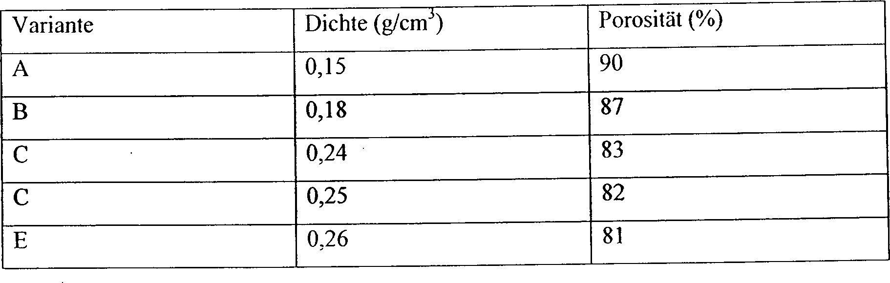
Durch veränderte Verhältnisse von Kohlenstofffasern, Pyrokohlenstoff und Siliziumkarbid können bei gleicher Dichte unterschiedliche Porositäten eingestellt werden.By changed conditions of carbon fibers, pyrocarbon and silicon carbide may be the same Dense different porosities be set.
Die Erfindung wird nachstehend auch anhand eines Beispiels näher erläutert, dem weitere Einzelheiten und Vorteile zu entnehmen sind.The Invention will be explained below with reference to an example, the Further details and advantages can be found.
Zur Herstellung eines Trägers wird ein Filzrohling zunächst mit Pyrokohlenstoff verdichtet. Dies kann im CVI-Verfahren erfolgen. Hierzu erfolgt eine Zersetzung eines kohlenstoffhaltigen Gases (z. B. Methan) bei Temperaturen zwischen 800 °C und 1800 °C bei Drucken zwischen 0,01 mbar und 1013 mbar absolut. Sodann erfolgt eine Bearbeitung des verdichteten Filzrohlings, um die Trägergeometrie zu erzielen. Die Bearbeitung kann maschinell erfolgen. Anschließend wird eine Hochtemperaturreinigung durchgeführt. Hierzu wird der bearbeitete Gegenstand bei ≥ 2000 °C im Vakuum gehalten. Halogenhaltige Gase werden dem Reaktionsraum zugeführt. Durch die Hochtemperaturreinigung ergibt sich als Gesamtrest Asche ein Wert < 5 ppm, wobei pro Einzelelement ein Wert < 0,05 ppm erzielbar ist, jeweils bezogen auf das Ausgangsgewicht. Schließlich erfolgt eine Verdichtung mit Siliziumkarbid, vorzugsweise im CVI-Verfahren. Dabei erfolgt die Zersetzung eines oder mehrerer silizium- und/oder kohlenstoffhaltiger Gase wie z. B. Methyltrichlorsilan bei Temperaturen zwischen 800 °C und 1600 °C und Drucken zwischen 0,01 mbar und 1013 mbar absolut.to Production of a carrier becomes a felt blank first compressed with pyrocarbon. This can be done in the CVI process. For this purpose, a decomposition of a carbon-containing gas (z. Methane) at temperatures between 800 ° C and 1800 ° C at pressures between 0.01 mbar and 1013 mbar absolute. Then there is a processing of the compacted felt blanks to achieve the carrier geometry. The Machining can be done by machine. Subsequently, a high-temperature cleaning carried out. For this purpose, the machined object is kept at ≥ 2000 ° C in a vacuum. halogenated Gases are supplied to the reaction space. By the high temperature cleaning As a total residue ash results in a value <5 ppm, where per single element Value <0.05 ppm is achievable, in each case based on the initial weight. Finally, a Silicon carbide compaction, preferably in the CVI process. there the decomposition of one or more silicon and / or carbon-containing takes place Gases such. As methyltrichlorosilane at temperatures between 800 ° C and 1600 ° C and pressures between 0.01 mbar and 1013 mbar absolute.
Alternativ kann das Verdichten mit Pyrokohlenstoff bzw. Verdichten mit Siliziumcarbid durch Flüssigimprägnierung durchgeführt werden. Dabei wird eine Matrix durch Tränken in kohlenstoff- und/oder siliziumhaltigen Harzen oder Lösungen wie Phenolharz aufgebracht. Anschließend erfolgt ein Glühen im Vakuum oder Schutzgas.alternative can compaction with pyrocarbon or compacting with silicon carbide by liquid impregnation carried out become. This is a matrix by soaking in carbon and / or silicon-containing resins or solutions applied like phenolic resin. This is followed by annealing in vacuo or inert gas.
Um z. B. bei Beibehaltung von Dichte und Porosität die Wärmeleitfähigkeit des Trägers zu ändern, können verschiedene Ausgangsfilzrohlinge benutzt werden. Ersetzt man z. B. Panoxfasern durch Pechfasern, so ergibt sich aufgrund höherer Wärmeleitfähigkeit der Fasern bei gleicher Porosität eine höhere Wärmeleitfähigkeit des Trägers.Around z. B. to maintain the density and porosity to change the thermal conductivity of the carrier, different Starting felt blanks are used. If you replace z. B. Panox fibers by pitch fibers, it results due to higher thermal conductivity of the fibers at the same porosity a higher one thermal conductivity of the carrier.
Claims (19)
Priority Applications (9)
| Application Number | Priority Date | Filing Date | Title |
|---|---|---|---|
| DE2003157698 DE10357698A1 (en) | 2003-12-09 | 2003-12-09 | Carrier for objects to be treated and method for producing such |
| PCT/EP2004/013838 WO2005059992A1 (en) | 2003-12-09 | 2004-12-06 | Carrier for receiving an object and method for the production of a carrier |
| JP2006543450A JP5052137B2 (en) | 2003-12-09 | 2004-12-06 | Support for receiving workpiece and method for manufacturing the support |
| KR1020067013773A KR101148897B1 (en) | 2003-12-09 | 2004-12-06 | Carrier for receiving an object and method for the production of a carrier |
| CNB2004800367829A CN100446213C (en) | 2003-12-09 | 2004-12-06 | Carrier for receiving an object and method for the production of a carrier |
| DE200450003727 DE502004003727D1 (en) | 2003-12-09 | 2004-12-06 | CARRIER FOR RECEIVING AN OBJECT AND METHOD FOR PRODUCING A CARRIER |
| EP04820417A EP1692718B1 (en) | 2003-12-09 | 2004-12-06 | Carrier for receiving an object and method for the production of a carrier |
| US10/581,739 US7919143B2 (en) | 2003-12-09 | 2004-12-06 | Carrier for receiving an object and method for the production of a carrier |
| TW93137876A TWI442508B (en) | 2003-12-09 | 2004-12-08 | The body of the object and the manufacturing method of the base body |
Applications Claiming Priority (1)
| Application Number | Priority Date | Filing Date | Title |
|---|---|---|---|
| DE2003157698 DE10357698A1 (en) | 2003-12-09 | 2003-12-09 | Carrier for objects to be treated and method for producing such |
Publications (1)
| Publication Number | Publication Date |
|---|---|
| DE10357698A1 true DE10357698A1 (en) | 2005-07-14 |
Family
ID=34672544
Family Applications (2)
| Application Number | Title | Priority Date | Filing Date |
|---|---|---|---|
| DE2003157698 Ceased DE10357698A1 (en) | 2003-12-09 | 2003-12-09 | Carrier for objects to be treated and method for producing such |
| DE200450003727 Active DE502004003727D1 (en) | 2003-12-09 | 2004-12-06 | CARRIER FOR RECEIVING AN OBJECT AND METHOD FOR PRODUCING A CARRIER |
Family Applications After (1)
| Application Number | Title | Priority Date | Filing Date |
|---|---|---|---|
| DE200450003727 Active DE502004003727D1 (en) | 2003-12-09 | 2004-12-06 | CARRIER FOR RECEIVING AN OBJECT AND METHOD FOR PRODUCING A CARRIER |
Country Status (8)
| Country | Link |
|---|---|
| US (1) | US7919143B2 (en) |
| EP (1) | EP1692718B1 (en) |
| JP (1) | JP5052137B2 (en) |
| KR (1) | KR101148897B1 (en) |
| CN (1) | CN100446213C (en) |
| DE (2) | DE10357698A1 (en) |
| TW (1) | TWI442508B (en) |
| WO (1) | WO2005059992A1 (en) |
Cited By (2)
| Publication number | Priority date | Publication date | Assignee | Title |
|---|---|---|---|---|
| DE102007054526A1 (en) * | 2007-11-07 | 2009-05-14 | Deutsches Zentrum für Luft- und Raumfahrt e.V. | Heat transfer element and system for the thermal treatment of substrates |
| DE102013218883A1 (en) * | 2013-09-19 | 2015-03-19 | Siltronic Ag | Apparatus and method for depositing semiconductor material from a gaseous phase onto a substrate wafer |
Families Citing this family (28)
| Publication number | Priority date | Publication date | Assignee | Title |
|---|---|---|---|---|
| DE102004060625A1 (en) * | 2004-12-16 | 2006-06-29 | Siltronic Ag | Coated semiconductor wafer and method and apparatus for producing the semiconductor wafer |
| NL1028867C2 (en) * | 2005-04-26 | 2006-10-27 | Xycarb Ceramics B V | Device for supporting a substrate and a method for manufacturing such a device. |
| DE102006055038B4 (en) * | 2006-11-22 | 2012-12-27 | Siltronic Ag | An epitaxated semiconductor wafer and apparatus and method for producing an epitaxied semiconductor wafer |
| US9012766B2 (en) | 2009-11-12 | 2015-04-21 | Silevo, Inc. | Aluminum grid as backside conductor on epitaxial silicon thin film solar cells |
| US9214576B2 (en) | 2010-06-09 | 2015-12-15 | Solarcity Corporation | Transparent conducting oxide for photovoltaic devices |
| US9773928B2 (en) | 2010-09-10 | 2017-09-26 | Tesla, Inc. | Solar cell with electroplated metal grid |
| US9800053B2 (en) | 2010-10-08 | 2017-10-24 | Tesla, Inc. | Solar panels with integrated cell-level MPPT devices |
| US9054256B2 (en) | 2011-06-02 | 2015-06-09 | Solarcity Corporation | Tunneling-junction solar cell with copper grid for concentrated photovoltaic application |
| JP6351601B2 (en) | 2012-10-04 | 2018-07-04 | ソーラーシティ コーポレーション | Photovoltaic device using electroplated metal grid |
| US9865754B2 (en) | 2012-10-10 | 2018-01-09 | Tesla, Inc. | Hole collectors for silicon photovoltaic cells |
| US9281436B2 (en) | 2012-12-28 | 2016-03-08 | Solarcity Corporation | Radio-frequency sputtering system with rotary target for fabricating solar cells |
| US9412884B2 (en) | 2013-01-11 | 2016-08-09 | Solarcity Corporation | Module fabrication of solar cells with low resistivity electrodes |
| US9219174B2 (en) | 2013-01-11 | 2015-12-22 | Solarcity Corporation | Module fabrication of solar cells with low resistivity electrodes |
| US9624595B2 (en) | 2013-05-24 | 2017-04-18 | Solarcity Corporation | Electroplating apparatus with improved throughput |
| US20150083046A1 (en) * | 2013-09-26 | 2015-03-26 | Applied Materials, Inc. | Carbon fiber ring susceptor |
| US10309012B2 (en) | 2014-07-03 | 2019-06-04 | Tesla, Inc. | Wafer carrier for reducing contamination from carbon particles and outgassing |
| US9899546B2 (en) | 2014-12-05 | 2018-02-20 | Tesla, Inc. | Photovoltaic cells with electrodes adapted to house conductive paste |
| US9947822B2 (en) | 2015-02-02 | 2018-04-17 | Tesla, Inc. | Bifacial photovoltaic module using heterojunction solar cells |
| WO2016142239A1 (en) * | 2015-03-11 | 2016-09-15 | Nv Bekaert Sa | Carrier for temporary bonded wafers |
| KR20170126899A (en) * | 2015-03-11 | 2017-11-20 | 엔브이 베카에르트 에스에이 | Temporarily bonded wafer carrier |
| WO2016142240A1 (en) * | 2015-03-11 | 2016-09-15 | Nv Bekaert Sa | Carrier for temporary bonded wafers |
| US9761744B2 (en) | 2015-10-22 | 2017-09-12 | Tesla, Inc. | System and method for manufacturing photovoltaic structures with a metal seed layer |
| US9842956B2 (en) | 2015-12-21 | 2017-12-12 | Tesla, Inc. | System and method for mass-production of high-efficiency photovoltaic structures |
| US9496429B1 (en) | 2015-12-30 | 2016-11-15 | Solarcity Corporation | System and method for tin plating metal electrodes |
| US10115838B2 (en) | 2016-04-19 | 2018-10-30 | Tesla, Inc. | Photovoltaic structures with interlocking busbars |
| US10672919B2 (en) | 2017-09-19 | 2020-06-02 | Tesla, Inc. | Moisture-resistant solar cells for solar roof tiles |
| US11190128B2 (en) | 2018-02-27 | 2021-11-30 | Tesla, Inc. | Parallel-connected solar roof tile modules |
| EP3980575A4 (en) * | 2019-06-06 | 2023-03-15 | Picosun Oy | Porous inlet |
Citations (4)
| Publication number | Priority date | Publication date | Assignee | Title |
|---|---|---|---|---|
| GB2172822A (en) * | 1985-03-25 | 1986-10-01 | Furniture Ind Res Ass | Vacuum chucks |
| DE10145686A1 (en) * | 2001-09-15 | 2003-04-24 | Schott Glas | Method and device for the contactless conveying of an object made of glass or glass ceramic |
| WO2003049157A1 (en) * | 2001-12-03 | 2003-06-12 | E. I. Du Pont De Nemours And Company | Transfer member with electric conductivity and its manufacturing method |
| US20030160044A1 (en) * | 2002-02-25 | 2003-08-28 | Besmann Theodore M. | High efficiency, oxidation resistant radio frequency susceptor |
Family Cites Families (18)
| Publication number | Priority date | Publication date | Assignee | Title |
|---|---|---|---|---|
| US4115528A (en) * | 1977-08-15 | 1978-09-19 | United Technologies Corporation | Method for fabricating a carbon electrode substrate |
| JPS60254610A (en) | 1984-05-31 | 1985-12-16 | Fujitsu Ltd | Manufacturing equipment of semiconductor |
| FR2614321A1 (en) * | 1987-04-27 | 1988-10-28 | Europ Propulsion | CARTRIDGE OF COMPOSITE MATERIALS FOR A DEVICE FOR THE PRODUCTION OF MONOCRYSTALS. |
| JP2628394B2 (en) * | 1990-02-26 | 1997-07-09 | 東芝セラミックス株式会社 | Susceptor |
| JPH03257074A (en) * | 1990-03-07 | 1991-11-15 | Sumitomo Electric Ind Ltd | Fiber-reinforced composite material |
| FR2671797B1 (en) * | 1991-01-18 | 1994-02-25 | Propulsion Ste Europeenne | METHOD FOR DENSIFICATION OF A POROUS SUBSTRATE BY A MATRIX CONTAINING CARBON. |
| JP3182212B2 (en) * | 1991-05-21 | 2001-07-03 | アブコウ・コーポレイション | Method for producing a densified porous billet and method for densifying a porous preform |
| JPH0672070B2 (en) * | 1991-07-25 | 1994-09-14 | 住友電気工業株式会社 | High-density fiber-reinforced composite material manufacturing apparatus and manufacturing method |
| JP3228546B2 (en) * | 1992-02-27 | 2001-11-12 | 京セラ株式会社 | Vacuum suction device and manufacturing method thereof |
| US5364513A (en) * | 1992-06-12 | 1994-11-15 | Moltech Invent S.A. | Electrochemical cell component or other material having oxidation preventive coating |
| JPH08181150A (en) | 1994-12-26 | 1996-07-12 | Touyoko Kagaku Kk | Heat treatment of substrate |
| JPH09209152A (en) * | 1996-02-06 | 1997-08-12 | Toshiba Corp | Substrate treating device |
| JPH1135391A (en) * | 1997-05-20 | 1999-02-09 | Topy Ind Ltd | Silicon carbide-coated susceptor |
| JP3092801B2 (en) * | 1998-04-28 | 2000-09-25 | 信越半導体株式会社 | Thin film growth equipment |
| JP2000031098A (en) | 1998-07-15 | 2000-01-28 | Disco Abrasive Syst Ltd | Holding table for material to be worked |
| US6444027B1 (en) * | 2000-05-08 | 2002-09-03 | Memc Electronic Materials, Inc. | Modified susceptor for use in chemical vapor deposition process |
| FR2818291B1 (en) * | 2000-12-19 | 2003-11-07 | Snecma Moteurs | DENSIFICATION OF HOLLOW POROUS SUBSTRATES BY CHEMICAL STEAM INFILTRATION |
| US8165700B2 (en) | 2008-10-02 | 2012-04-24 | Fisher-Rosemount Systems, Inc. | Complete integration of stand-alone batch operator interface capabilities into generic human machine interface using componentized objects |
-
2003
- 2003-12-09 DE DE2003157698 patent/DE10357698A1/en not_active Ceased
-
2004
- 2004-12-06 JP JP2006543450A patent/JP5052137B2/en active Active
- 2004-12-06 WO PCT/EP2004/013838 patent/WO2005059992A1/en active IP Right Grant
- 2004-12-06 CN CNB2004800367829A patent/CN100446213C/en active Active
- 2004-12-06 DE DE200450003727 patent/DE502004003727D1/en active Active
- 2004-12-06 EP EP04820417A patent/EP1692718B1/en active Active
- 2004-12-06 KR KR1020067013773A patent/KR101148897B1/en active IP Right Grant
- 2004-12-06 US US10/581,739 patent/US7919143B2/en active Active
- 2004-12-08 TW TW93137876A patent/TWI442508B/en active
Patent Citations (4)
| Publication number | Priority date | Publication date | Assignee | Title |
|---|---|---|---|---|
| GB2172822A (en) * | 1985-03-25 | 1986-10-01 | Furniture Ind Res Ass | Vacuum chucks |
| DE10145686A1 (en) * | 2001-09-15 | 2003-04-24 | Schott Glas | Method and device for the contactless conveying of an object made of glass or glass ceramic |
| WO2003049157A1 (en) * | 2001-12-03 | 2003-06-12 | E. I. Du Pont De Nemours And Company | Transfer member with electric conductivity and its manufacturing method |
| US20030160044A1 (en) * | 2002-02-25 | 2003-08-28 | Besmann Theodore M. | High efficiency, oxidation resistant radio frequency susceptor |
Non-Patent Citations (6)
| Title |
|---|
| JP 03181150 A (abstract) * |
| JP 03246931 A (abstract) * |
| JP 09209152 A (abstract) * |
| JP 11035391 A (abstract) * |
| JP 2000031098 A (abstract) * |
| JP 60254610 A (abstract) * |
Cited By (3)
| Publication number | Priority date | Publication date | Assignee | Title |
|---|---|---|---|---|
| DE102007054526A1 (en) * | 2007-11-07 | 2009-05-14 | Deutsches Zentrum für Luft- und Raumfahrt e.V. | Heat transfer element and system for the thermal treatment of substrates |
| DE102013218883A1 (en) * | 2013-09-19 | 2015-03-19 | Siltronic Ag | Apparatus and method for depositing semiconductor material from a gaseous phase onto a substrate wafer |
| DE102013218883B4 (en) | 2013-09-19 | 2018-12-06 | Siltronic Ag | Apparatus and method for depositing semiconductor material from a gaseous phase onto a substrate wafer |
Also Published As
| Publication number | Publication date |
|---|---|
| CN100446213C (en) | 2008-12-24 |
| KR20060126536A (en) | 2006-12-07 |
| US7919143B2 (en) | 2011-04-05 |
| DE502004003727D1 (en) | 2007-06-14 |
| US20070110975A1 (en) | 2007-05-17 |
| KR101148897B1 (en) | 2012-05-29 |
| JP5052137B2 (en) | 2012-10-17 |
| JP2007514306A (en) | 2007-05-31 |
| WO2005059992A1 (en) | 2005-06-30 |
| TW200525686A (en) | 2005-08-01 |
| TWI442508B (en) | 2014-06-21 |
| EP1692718A1 (en) | 2006-08-23 |
| CN1890792A (en) | 2007-01-03 |
| EP1692718B1 (en) | 2007-05-02 |
Similar Documents
| Publication | Publication Date | Title |
|---|---|---|
| DE10357698A1 (en) | Carrier for objects to be treated and method for producing such | |
| DE10123858B4 (en) | Atomic layer deposition process for forming a silicon nitride-containing thin film | |
| DE3531789A1 (en) | CARRIER FOR USE IN APPLYING A LAYER TO A SILICON SEMICONDUCTOR DISC | |
| DE112011105102T5 (en) | A method and apparatus for selectively depositing epitaxial germanium stressing alloys | |
| WO2014194892A1 (en) | Retainer, method for producing same and use thereof | |
| US10876227B2 (en) | Fiber with elemental additive(s) and method of making | |
| WO1999017345A1 (en) | Method for thermal curing of implantation-doped silicon carbide semiconductors | |
| DE2523067A1 (en) | METHOD FOR GROWING UP SILICON EPITAXIAL LAYERS | |
| DE3026030C2 (en) | Device part for semiconductor technology, method and device for its manufacture | |
| DE112018002713T5 (en) | SiC EPITAXY WAFER AND METHOD FOR THE PRODUCTION THEREOF | |
| DE2950827C2 (en) | Process for the epitaxial deposition of monocrystalline material | |
| EP1127176A1 (en) | Device for producing and processing semiconductor substrates | |
| DE102009015545B4 (en) | Coating system with activation element, its use and method for depositing a coating | |
| DE1544287B2 (en) | Process for producing a protective layer from silicon nitride | |
| EP1133593A1 (en) | Growth method for a crystalline structure | |
| EP2211378B1 (en) | Method of enhancing the longivity of transport devices | |
| DE1240997C2 (en) | METHOD FOR MANUFACTURING SEMICONDUCTOR BODIES FOR SEMICONDUCTOR ARRANGEMENTS | |
| DE69937529T2 (en) | Aluminum nitride component and process for its production | |
| DE102012214784B4 (en) | Carbon fiber filament chemical vapor deposition apparatus and method for producing the carbon fiber filaments | |
| EP1415332B1 (en) | Method and device for the production of epitaxial thin semiconductor layers | |
| EP3700861B1 (en) | Process and apparatus for removal of impurities from chlorosilanes | |
| DE3701691A1 (en) | Process for producing a furnace component | |
| DE1621247C3 (en) | 10/24/66 USA 588936 Method of Making High Strength Thread by Continuous Vacuum Coating General Electric Co., Schenectady, N.Y. (V.St.A.) | |
| DE10144431A1 (en) | Production of thin, preferably diffusion-limiting epitaxial semiconductor layers used in the production of high frequency components comprises simultaneously treating substrates in a low pressure batch reactor before further processing | |
| EP2058840A2 (en) | Heating blocks |
Legal Events
| Date | Code | Title | Description |
|---|---|---|---|
| OP8 | Request for examination as to paragraph 44 patent law | ||
| 8131 | Rejection |