DE10346741B3 - Determining and/or evaluating differential optical signal involves regulating intensity radiated into measurement arrangement with control parameter generated from incoming light intensity at receiver measured relative to phase position - Google Patents
Determining and/or evaluating differential optical signal involves regulating intensity radiated into measurement arrangement with control parameter generated from incoming light intensity at receiver measured relative to phase position Download PDFInfo
- Publication number
- DE10346741B3 DE10346741B3 DE10346741A DE10346741A DE10346741B3 DE 10346741 B3 DE10346741 B3 DE 10346741B3 DE 10346741 A DE10346741 A DE 10346741A DE 10346741 A DE10346741 A DE 10346741A DE 10346741 B3 DE10346741 B3 DE 10346741B3
- Authority
- DE
- Germany
- Prior art keywords
- light
- clock
- receiver
- signal
- light source
- Prior art date
- Legal status (The legal status is an assumption and is not a legal conclusion. Google has not performed a legal analysis and makes no representation as to the accuracy of the status listed.)
- Expired - Fee Related
Links
Classifications
-
- G—PHYSICS
- G01—MEASURING; TESTING
- G01V—GEOPHYSICS; GRAVITATIONAL MEASUREMENTS; DETECTING MASSES OR OBJECTS; TAGS
- G01V8/00—Prospecting or detecting by optical means
- G01V8/10—Detecting, e.g. by using light barriers
- G01V8/20—Detecting, e.g. by using light barriers using multiple transmitters or receivers
Landscapes
- Physics & Mathematics (AREA)
- Life Sciences & Earth Sciences (AREA)
- General Life Sciences & Earth Sciences (AREA)
- General Physics & Mathematics (AREA)
- Geophysics (AREA)
- Optical Communication System (AREA)
- Photometry And Measurement Of Optical Pulse Characteristics (AREA)
- Holo Graphy (AREA)
Abstract
Description
Gebiet der ErfindungTerritory of invention
Die Erfindung betrifft ein Verfahren zur Bestimmung und/oder Auswertung eines differentiellen optischen Signals nach dem Oberbegriff der Ansprüche 1 oder 4.The The invention relates to a method for determination and / or evaluation a differential optical signal according to the preamble of claims 1 or 4.
Photodioden weisen für moduliertes Licht eine von der absoluten Helligkeit abhängige Sensitivität auf, den sogenannten „ambient light effect". Somit hängt das Empfangssignal einer Reflexionslichtschranke nicht nur vom zu messenden Reflexionsgrad, sondern auch vom Umgebungslicht ab. Damit ist die Auswertung des Empfangssignals bei stark schwankenden Umgebungslichtverhältnissen nicht mehr zuverlässig möglich.photodiodes show for modulated light on a sensitivity dependent on the absolute brightness, the so-called "ambient light effect " that depends Reception signal of a reflection light barrier not only from the to be measured Reflectance, but also from the ambient light. This is the Evaluation of the received signal in strongly fluctuating ambient light conditions no longer reliable possible.
Aus
der dem Oberbegriff der Ansprüche
1 und 4 zu Grunde liegenden
Grundlegend existieren für eine derartige Regelung mit z.B. zwei Lichtquellen zwei unterschiedliche Regelverfahren:
- 1. Eine Lichtquelle sendet stets mit konstantem Pegel, die andere Lichtquelle wird nachgeregelt. Dies ist insbesondere dann sinnvoll, wenn eine Lichtquelle zum Messobjekt leuchtet, während die andere direkt in den Empfänger einstrahlt.
- 2. Beide Lichtquellen werden stets so geregelt, dass ihre Summenintensität gleich bleibt. Dies ist sinnvoll, wenn beide Lichtquellen das Messobjekt beleuchten.
- 1. One light source always transmits at a constant level, the other light source is readjusted. This is particularly useful when a light source to the measurement object lights up, while the other irradiates directly into the receiver.
- 2. Both light sources are always controlled so that their sum intensity remains the same. This is useful if both light sources illuminate the measurement object.
Die
beiden Regelverfahren können
auch kombiniert werden. Allerdings muss sichergestellt sein, dass die
Regelbedingung nicht durch Ausschalten von beiden Lichtquellen erfüllt wird.
In den zur Erläuterung
herangezogenen folgenden Formeln haben die Formelzeichen folgende
Bedeutung: 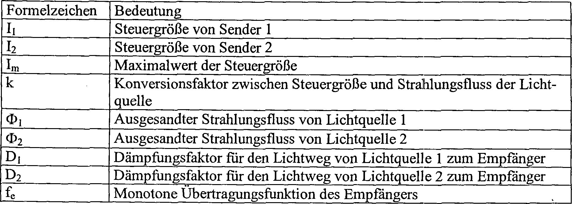
Es
wird vorausgesetzt, dass die Konversionsfunktion der Lichtquelle
zwischen Steuergröße und Strahlungsfluss
für die
folgenden Gleichungen linear ist.
Die
Regelbedingung lautet:
Für das Regelprinzip
1 führt
die folgende Zusatzbedingung ein:
Damit
ist I2 Ausgangssignal und ergibt sich zu: ![]()
![]()
Bei
Anwendung des Regelprinzips 2 gilt die Zusatzbedingung:
Daraus
folgt für
beispielsweise I2: ![]()
![]()
In
Bis jetzt werden zur Realisierung des Detektors im Wesentlichen die folgenden Verfahren angewandt:
- – Das Empfangssignal wird in jeder Halbperiode abgetastet und die Differenz der beiden Abtastwerte bezüglich des Vorzeichens bewertet.
- – Das Empfangssignal wird synchron demoduliert und das Vorzeichen des Demodulationsproduktes zur Steuerung des Integrators verwendet.
- The received signal is sampled every half cycle and the difference of the two samples is evaluated with respect to the sign.
- The received signal is synchronously demodulated and the sign of the demodulation product used to control the integrator.
Die Integration erfolgt bei der bisher analogen Realisierung durch eine klassische Integratorschaltung, bei einer digitalen Realisierung ist der Integrator ein vom Takt gesteuerter Zähler, dessen Zählrichtung durch das ermittelte Vorzeichen gesteuert wird.The Integration takes place in the previously analogous realization by a classic integrator circuit, in a digital implementation the integrator is a clock controlled counter whose counting direction is controlled by the detected sign.
Da die bisherige digitale Implementierung eine direkte Umsetzung des analogen Regelkreises darstellt, werden nicht die Vorteile eines rein digitalen Systems genutzt. Insbesondere treten in der Vorzeichenerkennung Analogspannungen auf, die sehr empfindlich verglichen werden müssen, ohne ein Schwingen des Systems zu verursachen. Hierzu wird meist eine Hysterese verwendet, die die Systemempfindlichkeit herabsetzt.There the previous digital implementation a direct implementation of the Analogue loop represents not the advantages of a used purely digital system. In particular, occur in sign recognition Analog voltages on which must be compared very sensitive, without to cause a swing of the system. This is usually a Used hysteresis, which minimizes the system sensitivity.
Zusammenfassung der ErfindungSummary the invention
Ausgehend von diesem Stand der Technik liegt der vorliegenden Erfindung die Aufgabe zu Grunde, eine vereinfachte digitale Implementierung dieses Verfahrens möglichst ohne Verlust der Empfindlichkeit zu schaffen.outgoing from this prior art, the present invention is the Task, a simplified digital implementation of this Procedure as possible to create without loss of sensitivity.
Diese Aufgabe wird durch ein Verfahren mit den Merkmalen der Ansprüche 1 oder 4 gelöst.These The object is achieved by a method having the features of claims 1 or 4 solved.
Diese Lösungen beruhen auf der Beobachtung, dass zur Beurteilung, welcher Sender stärker sendet es ausreichend ist, das Empfangssignal bezüglich der Phasenlage zu beurteilen. Eine zusätzliche Betrachtung der Amplitude ist grundsätzlich nicht erforderlich. Aufgrund dieser Erkenntnis lassen sich digitale Ausgestaltungen schnell und günstig realisieren, ohne dass es zu Fehlsignalen kommt. Dabei besteht sowohl die Möglichkeit, die so gewonnene Regelgröße als Licht über einen der Sender oder eine weitere Lichtquelle als Kompensationslichtquelle wieder in die Regelstrecke einzubringen, alternativ kann aber auch das so gewonnene Signal als Stromsignal am Empfänger hinzuaddiert werden. Die zweite Alternative berücksichtigt zwar nicht sämtliche Störeinflüsse, die sich aufgrund der verwendeten Bauteile ergeben können, unter Umständen genügt jedoch eine derartige Lösung insbesondere für günstigere Ausführungsformen, bei denen es eventuell nicht auf eine vollständige Positions- oder Annäherungserkennung ankommt.These solutions are based on the observation that in order to judge which transmitter is transmitting stronger it is sufficient to judge the received signal with respect to the phase angle. An additional consideration of the amplitude is basically not required. Based on this knowledge, digital designs can be implemented quickly and inexpensively without the occurrence of false signals. There is both the possibility It is also possible to introduce the control variable thus obtained back into the controlled system as light via one of the transmitters or a further light source as a compensation light source, but alternatively the signal obtained in this way can also be added as a current signal at the receiver. Although the second alternative does not take into account all the disturbances that may arise due to the components used, under certain circumstances, such a solution is sufficient in particular for more favorable embodiments in which it may not be important to a complete position or proximity detection.
Bei einer Ausgestaltung nach Anspruch 2 erfolgt die Kompensation über die Lichtquellen selbst. Auch hier besteht die Möglichkeit, den als Regelgröße ermittelten Strom entsprechend skaliert dem Strom der entsprechend schwächeren Lichtquelle hinzuzuaddieren. Das Umschalten der Phasenlage ist dann gleichbedeutend mit dem Umschalten dieses zusätzlichen Stromes von der einen LED auf die andere. Weitere Vorteile ergeben sich aus den Unteransprüchen und der nachfolgenden Beschreibung.at an embodiment according to claim 2, the compensation over the Light sources themselves. Again, there is the possibility of the determined as a controlled variable current correspondingly scaled the current of the correspondingly weaker light source hinzuzuaddieren. Switching the phase position is then synonymous with the switching of this extra Current from one LED to the other. Further advantages result from the dependent claims and the description below.
Im Folgenden wird die Erfindung anhand der beigefügten Figuren näher erläutert. Es zeigen:in the The invention will be explained in more detail below with reference to the attached figures. It demonstrate:
Beschreibung bevorzugter Ausführungsbeispieledescription preferred embodiments
Die Figuren zeigen ein Verfahren zur Bestimmung und/oder Auswertung eines differenziellen optischen Signals mit wenigstens zwei ersten Lichtquellen S1, S2, die Licht zeitsequenziell getaktet, phasenweise aussenden. Zum Empfang des so ausgesandten Signals ist wenigstens ein Empfänger E vorgesehen, der den von den ersten Lichtquellen S1, S2 stammenden taktsynchronen Wechsellichtanteil empfängt. Die in der Messanordnung durch wenigstens eine Lichtquelle S1, S2, die auch eine Kompensationslichtquelle K sein kann, eingestrahlte Lichtintensität wird dann so geregelt, dass der taktsynchrone Wechsellichtanteil, der zwischen den verschiede nen Phasen auftritt, am Empfänger E zu Null wird. Dies wurde eingangs in der Beschreibungseinleitung näher erläutert.The Figures show a method for the determination and / or evaluation a differential optical signal having at least two first ones Light sources S1, S2, the light clocked time sequentially, emitting in phases. For receiving the signal thus emitted, at least one receiver E is provided, the isochronous originating from the first light sources S1, S2 Alternating light component receives. The in the measuring arrangement by at least one light source S1, S2, which can also be a compensation light source K, irradiated Light intensity is then controlled so that the isochronous change light component, which occurs between the various phases NEN, at the receiver E. Becomes zero. This was explained in detail in the introduction to the description.
Hiervon
ausgehend wird im Folgenden nun allgemein das verfolgte Prinzip
erläutert,
bevor dann auf die genaueren Implementierungen gemäß den
Zur
Regelung der eingestrahlten Lichtintensität wird nicht mehr das Empfangssignal
wie bei einer analogen Auswertung hinsichtlich seiner Amplitude
beurteilt und bewertet, sondern stattdessen wird das Empfangssignal
am Empfänger
E bezüglich
der Phasenlage bestimmt und damit eine Stellgröße erzeugt. Diese Stellgröße R kann
entweder als Lichtsignal durch einen entsprechenden Strom an wenigstens
eine der ersten Lichtquellen S1, S2 übermittelt werden, es ist jedoch
ebenso möglich,
das Ganze durch ein Stromsignal dem Empfänger durch Stromaddition zuzuleiten.
Die weitere Lichtquelle, die die Lichtintensität regelt, kann insofern eine
der ersten Lichtquellen S1, S2 sein. Alternativ kann es aber auch
eine weitere Lichtquelle K sein, die dem Empfänger zugeordnet ist, wobei
durch diese weitere Lichtquelle K die Regelung so erfolgt, dass
sie ihre Phase wechselt, indem diese weitere Lichtquelle K über wenigstens
ein ExOr-Gatter
Zur
Erzeugung der Stellgröße R wird
der ganzzahlige Wert der Phasenlage, also z.B. +1 oder –1 entsprechend
0° oder
180° mittels
eines Zählers
Z integriert. Das digitalisierte Empfangssignal wird als Richtungssignal
für den
Empfänger
E verwendet. Das Empfangssignal wird einem Flip-Flop
Um ein schnelleres Hochfahren des Zählers Z zu erreichen, kann der Zählerstand des Zählers Z bedarfsweise vorgegeben sein oder ist ggf. softwaremäßig vorgebbar. Um die Auflösung des Reglers möglichst vollständig auszunutzen, kann ergänzend die Stellgröße R einen vorgegebenen oder vorgebbaren, festen Anteil aufweisen. Dies ist insbesondere dann der Fall, wenn im konkreten Anwendungsfall stets nur ein bestimmter Regelbereich benutzt wird. Für den dann verbleibenden Regelbereich, der durch den variablen Anteil der Stellgröße bestimmt wird, ergibt sich damit eine erheblich gesteigerte Auflösung. Dieser variable Anteil der Stellgröße wird zu dem festen Anteil durch Stromaddition z. B. an der Lichtquelle S1, S2, K addiert. Ergänzend kann die Stellgröße R durch Stromaddition zu der oder den schwächeren Lichtquellen S1, S2, K taktweise hinzuaddiert werden.Around a faster startup of the counter Z can reach the meter reading of the meter Z may be required or may be specified by software. To the resolution as fully as possible of the controller, can be complementary the manipulated variable R a have predetermined or predefinable, fixed proportion. This is especially the case, if always in the concrete application only a certain control range is used. For the remaining control area, which is determined by the variable component of the manipulated variable, results thus a considerably increased resolution. This variable component the manipulated variable is to the solid portion by current addition z. B. at the light source S1, S2, K added. In addition can the manipulated variable R through Current addition to the weaker light source or sources S1, S2, K be added cyclically.
Unter
Bezug auf die Figuren wird nun die Erfindung an Ausführungsbeispielen
noch näher
erläutert. Gemäß
Beiden
im Folgenden vorgestellten Implementierungen ist gemeinsam, dass
das Empfangssignal bis zur Begrenzung verstärkt wird, sodass ein Rechtecksignal
vorliegt. Dieses Rechtecksignal kann gemäß
Die
Implementierung kann gemäß
- – Ein Zählschritt je Periode
- – Der Empfänger E muss lediglich die Phase regenerieren
- – Der Empfänger E kann mit extrem hoher Verstärkung ausgelegt werden
- – Ein Takt synchroner Betrieb des Zählers Z
- – Eine Schaltung zur Erzeugung eines Abtastimpulses
- - One counting step per period
- - The receiver E only has to regenerate the phase
- - The receiver E can be designed with extremely high gain
- - One clock synchronous operation of the counter Z
- - A circuit for generating a sampling pulse
Bei
der alternativen Implementierung gemäß
- – Ein Zählschritt je Periode, bei Richtungswechsel je Halbperiode
- – Der Empfänger muss lediglich Phase regenerieren, Phasenverschiebung ist notwendig
- – Der Empfänger kann mit extrem hoher Verstärkung ausgelegt werden
- – Ein asynchroner Takt des Zählers
- – Eine Schaltung zur Verriegelung des Empfangssignals bei Flankenwechsel des Taktes ist notwendig
- - One counting step per period, with change of direction per half-period
- - The receiver only has to regenerate phase, phase shift is necessary
- - The receiver can be designed with extremely high gain
- - An asynchronous clock of the counter
- - A circuit for locking the received signal at edge change of the clock is necessary
Wie
bei der Implementierung gemäß
Aus
der
Dies
wird nach der vorliegenden Erfindung gemäß
Der Zähler Z kann überlaufen. Dies führt dazu, dass, wenn der Regelkreis sich aufgrund ungünstiger optischer Dämpfungsverhältnisse nicht ausregeln kann, der Regelkreis schwingt, so dass der Zähler Z permanent zählt und die Intensität von einer oder beiden LEDs sich zyklisch ändert. Um dies zu verhindern, wird der Überlauf durch eine geeignete Beschaltung verhindert. Hierzu erfolgt bei Erreichen des maximalen bzw. minimalen Zählerstandes eine Verriegelung des Zählers Z für die jeweilige Zählrichtung. Die Implementierung dieser Verriegelung erfolgt beispielsweise über eine Kopplung des Übertragungsausgangs auf den ENABLE-Eingang des Zählers Z. Die genaue Ausführung ist von der gewählten Zählerrealisierung abhängig.Of the counter Z can overflow. this leads to to that, if the control loop is due to unfavorable optical damping ratios can not compensate, the control loop swings, so that the counter Z permanently counts and the intensity of one or both LEDs changes cyclically. To prevent this, will be the overflow prevented by a suitable wiring. This is done at Reaching the maximum or minimum counter reading a lock of the meter Z for the respective counting direction. The implementation of this lock is done for example via a Coupling of the transmission output to the ENABLE input of the counter Z. The exact execution is chosen by the counter implementation dependent.
Der Zählerstand ändert sich bei den aufgeführten Implementierungen je Takt um einen Schritt. Durch eine geeignete Logik, welche erkennt, dass die letzten Zählschritte in die gleiche Richtung gingen, kann auch ein größerer Zählschritt ausgelöst werden. Dies entspricht einem D-Anteil im Regler.Of the Meter reading changes at the listed Implementations per measure by one step. By a suitable Logic, which recognizes that the last counts in the same direction can go, also a larger counting step triggered become. This corresponds to a D component in the controller.
Um ein Einschwingen des Reglers zu beschleunigen kann der Zähler Z auch eine Möglichkeit besitzen, ihn auf einen vorgegeben Zählerstand zu setzen.Around The counter Z can also speed up a settling of the regulator a possibility have to set it to a preset counter reading.
Bewegt
sich die Änderung
der optischen Übertragung
nur in einem engen Bereich, so besteht die Möglichkeit diesen Bereich heraus
zu vergrößern. Hierzu
wird die Stellgröße aus zwei
Teilen gebildet, nämlich
einer festen Einstellung in Form eines Offsets und einem variablen
Anteil, der vom Regler kontrolliert wird. Im Falle einer Kompensation,
wie sie in der oben erläuterten
- 1010
- Reglerregulator
- 1111
- Flip-FlopFlip-flop
- 1212
- Taktgeberclock
- 1313
- Transimpendanzverstärkertransimpedance
- 1414
- Komparatorcomparator
- 1515
- Amplitudenbegrenzeramplitude
- 1616
- Flip-FlopFlip-flop
- 17, 18, 2217 18, 22
- DigitalanalogumsetzerDigital to analog converter
- 1919
- Verzögerungsschaltungdelay circuit
- 21, 2321 23
- ExOr-GatterEXOR gate
- 2424
- Modulatormodulator
- dd
- Phasenverschiebungphase shift
- Ee
- Empfängerreceiver
- E(S1), E(S2)E (S1), E (S2)
- Empfangssignale von S1, S2receive signals from S1, S2
- KK
- weitere LichtquelleFurther light source
- RR
- Stellgrößemanipulated variable
- S1, S2S1, S2
- Erste LichtquelleFirst light source
- ZZ
- Zählercounter
Claims (15)
Priority Applications (8)
| Application Number | Priority Date | Filing Date | Title |
|---|---|---|---|
| DE10346741A DE10346741B3 (en) | 2003-10-08 | 2003-10-08 | Determining and/or evaluating differential optical signal involves regulating intensity radiated into measurement arrangement with control parameter generated from incoming light intensity at receiver measured relative to phase position |
| JP2006530112A JP4745969B2 (en) | 2003-10-08 | 2004-10-07 | Method for detecting and / or evaluating a differential optical signal |
| AT04790170T ATE361477T1 (en) | 2003-10-08 | 2004-10-07 | METHOD FOR DETERMINING AND/OR EVALUating A DIFFERENTIAL OPTICAL SIGNAL |
| PCT/EP2004/011197 WO2005036209A1 (en) | 2003-10-08 | 2004-10-07 | Method for determining and/or evaluating a differential optical signal |
| EP04790170A EP1671160B1 (en) | 2003-10-08 | 2004-10-07 | Method for determining and/or evaluating a differential optical signal |
| DE502004003717T DE502004003717D1 (en) | 2003-10-08 | 2004-10-07 | Method for determining and / or evaluating a differential optical signal |
| ES04790170T ES2287780T3 (en) | 2003-10-08 | 2004-10-07 | METHOD FOR THE DETERMINATION AND / OR ANALYSIS OF A DIFFERENTIAL OPTICAL SIGNAL. |
| US10/575,148 US7589303B2 (en) | 2003-10-08 | 2004-10-07 | Method of determining and/or evaluating a differential optical signal |
Applications Claiming Priority (1)
| Application Number | Priority Date | Filing Date | Title |
|---|---|---|---|
| DE10346741A DE10346741B3 (en) | 2003-10-08 | 2003-10-08 | Determining and/or evaluating differential optical signal involves regulating intensity radiated into measurement arrangement with control parameter generated from incoming light intensity at receiver measured relative to phase position |
Publications (1)
| Publication Number | Publication Date |
|---|---|
| DE10346741B3 true DE10346741B3 (en) | 2005-03-24 |
Family
ID=34202432
Family Applications (2)
| Application Number | Title | Priority Date | Filing Date |
|---|---|---|---|
| DE10346741A Expired - Fee Related DE10346741B3 (en) | 2003-10-08 | 2003-10-08 | Determining and/or evaluating differential optical signal involves regulating intensity radiated into measurement arrangement with control parameter generated from incoming light intensity at receiver measured relative to phase position |
| DE502004003717T Active DE502004003717D1 (en) | 2003-10-08 | 2004-10-07 | Method for determining and / or evaluating a differential optical signal |
Family Applications After (1)
| Application Number | Title | Priority Date | Filing Date |
|---|---|---|---|
| DE502004003717T Active DE502004003717D1 (en) | 2003-10-08 | 2004-10-07 | Method for determining and / or evaluating a differential optical signal |
Country Status (7)
| Country | Link |
|---|---|
| US (1) | US7589303B2 (en) |
| EP (1) | EP1671160B1 (en) |
| JP (1) | JP4745969B2 (en) |
| AT (1) | ATE361477T1 (en) |
| DE (2) | DE10346741B3 (en) |
| ES (1) | ES2287780T3 (en) |
| WO (1) | WO2005036209A1 (en) |
Cited By (14)
| Publication number | Priority date | Publication date | Assignee | Title |
|---|---|---|---|---|
| EP1777670A2 (en) * | 2005-10-19 | 2007-04-25 | IMOS Gubela GmbH | Smoke detector |
| WO2008122938A3 (en) * | 2007-04-06 | 2009-01-29 | Koninkl Philips Electronics Nv | Line-of-sight optical detection system, and communication system |
| EP2602635A1 (en) | 2011-12-06 | 2013-06-12 | ELMOS Semiconductor AG | Method for measuring a transfer route by means of compensating amplitude measurement and delta-sigma method and device for performing the method |
| DE102012015442A1 (en) | 2012-02-23 | 2013-08-29 | Elmos Semiconductor Ag | Method and sensor system for inductive measurement of the characteristics of a transmission path of a measuring system between transmitter coil and receiver coil |
| EP2653885A1 (en) | 2012-04-18 | 2013-10-23 | ELMOS Semiconductor AG | Method and sensor system for measuring the transfer properties of a transfer segment of a measuring system between transmitter and recipient |
| DE102013002676A1 (en) | 2013-02-12 | 2014-08-14 | Elmos Semiconductor Ag | Compensated sensor system with a sensitivity adjustable receiver as compensating element |
| DE102014002486A1 (en) | 2013-02-27 | 2014-08-28 | Elmos Semiconductor Ag | Device for optical measurement of transmission path of compensating optical sensor system, has reflector changing spatial distribution of light of transmitter on receiver, and compensation window reducing intensity of light on receiver |
| DE202014007446U1 (en) | 2013-02-27 | 2015-01-22 | Elmos Semiconductor Ag | Compensating optical sensor system |
| DE102014002194A1 (en) | 2014-02-12 | 2015-08-13 | Elmos Semiconductor Aktiengesellschaft | Compensating optical microsystem |
| EP2924463A1 (en) | 2014-03-25 | 2015-09-30 | ELMOS Semiconductor AG | Sensor system for detection of characteristics of a transmission link |
| EP2924459A1 (en) | 2014-03-25 | 2015-09-30 | ELMOS Semiconductor AG | Sensor system for identifying at least one object in a transmission line |
| EP2924466A1 (en) | 2014-03-25 | 2015-09-30 | ELMOS Semiconductor AG | Sensor system for identifying at least one object of a transmission line |
| DE102014017237A1 (en) | 2014-11-21 | 2016-05-25 | Mechaless Systems Gmbh | Measuring system for energy-saving optical distance measurement |
| EP3124993A1 (en) | 2013-08-22 | 2017-02-01 | ELMOS Semiconductor Aktiengesellschaft | Disturbance-compensated device for measuring an optical signal transfer route |
Families Citing this family (26)
| Publication number | Priority date | Publication date | Assignee | Title |
|---|---|---|---|---|
| DE102007040957A1 (en) * | 2007-08-30 | 2009-03-05 | Miele & Cie. Kg | Upright vacuum cleaner |
| EP2405283B1 (en) | 2010-07-06 | 2014-03-05 | Mechaless Systems GmbH | Optoelectronic measuring assembly with a compensation light source |
| DE102010027499A1 (en) | 2010-07-16 | 2012-01-19 | Mechaless Systems Gmbh | Optical control, in particular push-button or switch |
| EP2418512A1 (en) | 2010-07-30 | 2012-02-15 | Mechaless Systems GmbH | Optoelectronic measuring assembly with compensation for external light sources |
| DE112012002330A5 (en) * | 2011-05-31 | 2014-03-20 | Mechaless Systems Gmbh | Display with integrated optical transmitter |
| WO2013113456A1 (en) | 2012-02-03 | 2013-08-08 | Mechaless Systems Gmbh | Compensation of an optical sensor via printed circuit board |
| DE102015002282A1 (en) | 2014-05-09 | 2015-11-12 | Elmos Semiconductor Aktiengesellschaft | Device and method for especially three-dimensional optical scanning and measuring of objects and for object recognition by means of light transit time measurement |
| US9937124B2 (en) | 2014-09-11 | 2018-04-10 | International Business Machines Corporation | Microchip substance delivery devices having low-power electromechanical release mechanisms |
| DE102014019773B4 (en) | 2014-12-17 | 2023-12-07 | Elmos Semiconductor Se | Device and method for distinguishing between solid objects, cooking fumes and smoke using the display of a mobile telephone |
| DE102014019172B4 (en) | 2014-12-17 | 2023-12-07 | Elmos Semiconductor Se | Device and method for distinguishing between solid objects, cooking fumes and smoke using a compensating optical measuring system |
| US9734371B2 (en) * | 2015-03-31 | 2017-08-15 | International Business Machines Corporation | Hybrid tag for radio frequency identification system |
| DE102015006174B3 (en) * | 2015-05-08 | 2016-08-11 | Elmos Semiconductor Aktiengesellschaft | Device and method for measuring an optical, capacitive, inductive transmission path |
| US10881788B2 (en) | 2015-10-30 | 2021-01-05 | International Business Machines Corporation | Delivery device including reactive material for programmable discrete delivery of a substance |
| DE102015015245A1 (en) | 2015-11-18 | 2017-05-18 | Elmos Semiconductor Aktiengesellschaft | Simple gesture recognition device |
| DE102015015248A1 (en) | 2015-11-18 | 2017-05-18 | Elmos Semiconductor Aktiengesellschaft | Simple gesture recognition device |
| DE102015015244A1 (en) | 2015-11-18 | 2017-05-18 | Elmos Semiconductor Aktiengesellschaft | Simple gesture recognition device |
| DE102015015246A1 (en) | 2015-11-18 | 2017-05-18 | Elmos Semiconductor Aktiengesellschaft | Simple gesture recognition device |
| DE102015015390A1 (en) | 2015-11-18 | 2017-05-18 | Elmos Semiconductor Ag | Simple gesture recognition device |
| DE102015015389A1 (en) | 2015-11-18 | 2017-05-18 | Elmos Semiconductor Ag | Simple gesture recognition device |
| EP3208582B1 (en) * | 2016-02-17 | 2021-01-20 | Mettler-Toledo GmbH | Difference measuring circuit and a weighing apparatus with force compensation |
| DE102017106813B4 (en) | 2016-05-09 | 2018-01-18 | Elmos Semiconductor Aktiengesellschaft | Device and associated method for autonomous address configuration of configurable, flexible sensor bands |
| DE102017106812B4 (en) | 2016-05-09 | 2018-01-11 | Elmos Semiconductor Aktiengesellschaft | Device and associated method for autonomous address configuration of configurable, flexible LED sensor strips |
| DE102017106811B4 (en) | 2016-05-09 | 2018-01-11 | Elmos Semiconductor Aktiengesellschaft | Device and associated method for autonomous address configuration of configurable, flexible LED strips |
| DE102017100308B3 (en) | 2016-12-06 | 2018-05-30 | Elmos Semiconductor Aktiengesellschaft | Device and method for measuring an optical, capacitive, inductive transmission path with reduced EMC sensitivity |
| DE102017100306B4 (en) | 2017-01-09 | 2021-08-12 | Elmos Semiconductor Se | Device and method for measuring an optical, capacitive, inductive transmission path by means of multiple modulation |
| DE102017100305B4 (en) | 2017-01-09 | 2021-08-12 | Elmos Semiconductor Se | Device and method for measuring an optical, capacitive, inductive transmission path by means of multiple modulation |
Citations (2)
| Publication number | Priority date | Publication date | Assignee | Title |
|---|---|---|---|---|
| EP0706648B1 (en) * | 1993-07-02 | 1997-09-03 | Gerd Reime | Arrangement for measuring or detecting a change in a retro-reflective component |
| DE10300223B3 (en) * | 2003-01-03 | 2004-06-24 | Gerd Reime | Optoelectronic measuring device with stray light compensation provided by intensity regulation of additional light source |
Family Cites Families (7)
| Publication number | Priority date | Publication date | Assignee | Title |
|---|---|---|---|---|
| JPS62291508A (en) * | 1986-06-12 | 1987-12-18 | Stanley Electric Co Ltd | Object detecting apparatus |
| US5254853A (en) * | 1990-02-14 | 1993-10-19 | Stefan Reich | Optical sensing device |
| DE4004530C2 (en) | 1990-02-14 | 1999-07-29 | Stefan Reich | Optical distance measurement |
| US5610394A (en) * | 1996-04-29 | 1997-03-11 | Itron, Inc. | Rotation monitor disturbance neutralization system |
| JP2000208012A (en) * | 1999-01-11 | 2000-07-28 | Yamatake Corp | Object detecting sensor |
| DE10106998C2 (en) * | 2000-11-04 | 2003-01-23 | Stefan Reich | Method and device for optical object detection |
| DE10318764A1 (en) * | 2002-05-08 | 2003-11-20 | Stefan Reich | Optical object detection method in which a number of light transmitters are pulsed and aimed at an object from different positions so that reflected signals can be detected and analyzed synchronized with the transmission sequence |
-
2003
- 2003-10-08 DE DE10346741A patent/DE10346741B3/en not_active Expired - Fee Related
-
2004
- 2004-10-07 JP JP2006530112A patent/JP4745969B2/en active Active
- 2004-10-07 WO PCT/EP2004/011197 patent/WO2005036209A1/en active IP Right Grant
- 2004-10-07 EP EP04790170A patent/EP1671160B1/en active Active
- 2004-10-07 DE DE502004003717T patent/DE502004003717D1/en active Active
- 2004-10-07 US US10/575,148 patent/US7589303B2/en active Active
- 2004-10-07 ES ES04790170T patent/ES2287780T3/en active Active
- 2004-10-07 AT AT04790170T patent/ATE361477T1/en not_active IP Right Cessation
Patent Citations (2)
| Publication number | Priority date | Publication date | Assignee | Title |
|---|---|---|---|---|
| EP0706648B1 (en) * | 1993-07-02 | 1997-09-03 | Gerd Reime | Arrangement for measuring or detecting a change in a retro-reflective component |
| DE10300223B3 (en) * | 2003-01-03 | 2004-06-24 | Gerd Reime | Optoelectronic measuring device with stray light compensation provided by intensity regulation of additional light source |
Cited By (28)
| Publication number | Priority date | Publication date | Assignee | Title |
|---|---|---|---|---|
| EP1777670A2 (en) * | 2005-10-19 | 2007-04-25 | IMOS Gubela GmbH | Smoke detector |
| EP1777670A3 (en) * | 2005-10-19 | 2007-07-25 | IMOS Gubela GmbH | Smoke detector |
| WO2008122938A3 (en) * | 2007-04-06 | 2009-01-29 | Koninkl Philips Electronics Nv | Line-of-sight optical detection system, and communication system |
| EP2602635A1 (en) | 2011-12-06 | 2013-06-12 | ELMOS Semiconductor AG | Method for measuring a transfer route by means of compensating amplitude measurement and delta-sigma method and device for performing the method |
| WO2013083346A1 (en) | 2011-12-06 | 2013-06-13 | Elmos Semiconductor Ag | Method for measuring a transmission path by means of compensating amplitude measurement and the delta-sigma method and device for carrying out the method |
| US9658323B2 (en) | 2011-12-06 | 2017-05-23 | Elmos Semiconductor Ag | Method for measuring a transmission path by means of compensating amplitude measurement and delta-sigma method, and device for implementing the method |
| US9520953B2 (en) | 2012-02-23 | 2016-12-13 | Elmos Semiconductor Ag | Method and sensor system for measuring the properties of a transmission path of a measuring system between a transmitter and a receiver |
| DE102013022403B3 (en) | 2012-02-23 | 2023-07-27 | Elmos Semiconductor Se | Sensor system for acoustic measurement of the properties of a transmission path of a measurement system between loudspeaker and microphone |
| DE102013000380B4 (en) | 2012-02-23 | 2022-11-17 | Elmos Semiconductor Se | Method for acoustic measurement of the properties of a transmission path of a measurement system between loudspeaker and microphone |
| DE102012015442A1 (en) | 2012-02-23 | 2013-08-29 | Elmos Semiconductor Ag | Method and sensor system for inductive measurement of the characteristics of a transmission path of a measuring system between transmitter coil and receiver coil |
| DE102013000380A1 (en) | 2012-02-23 | 2013-08-29 | Elmos Semiconductor Ag | Method and sensor system for the acoustic measurement of the characteristics of a transmission path of a measuring system between loudspeaker and microphone |
| DE102012015423A1 (en) | 2012-02-23 | 2013-08-29 | Elmos Semiconductor Ag | Method and sensor system for capacitive measurement of the properties of a transmission path of a measuring system between a transmitter electrode and a receiver electrode |
| EP2653885A1 (en) | 2012-04-18 | 2013-10-23 | ELMOS Semiconductor AG | Method and sensor system for measuring the transfer properties of a transfer segment of a measuring system between transmitter and recipient |
| WO2013156557A1 (en) | 2012-04-18 | 2013-10-24 | Elmos Semiconductor Ag | Sensor system and method for measuring the transmission properties of a transmission path of a measuring system between a transmitter and a receiver |
| US9223010B2 (en) | 2013-02-12 | 2015-12-29 | Elmos Semiconductor Ag | Receiver compensation by adjusting receiver sensitivity |
| DE102013002676A1 (en) | 2013-02-12 | 2014-08-14 | Elmos Semiconductor Ag | Compensated sensor system with a sensitivity adjustable receiver as compensating element |
| DE102013002676B4 (en) | 2013-02-12 | 2023-06-29 | Elmos Semiconductor Se | Compensated sensor system with a receiver with adjustable sensitivity as a compensating element |
| DE102014002486A1 (en) | 2013-02-27 | 2014-08-28 | Elmos Semiconductor Ag | Device for optical measurement of transmission path of compensating optical sensor system, has reflector changing spatial distribution of light of transmitter on receiver, and compensation window reducing intensity of light on receiver |
| DE202014007446U1 (en) | 2013-02-27 | 2015-01-22 | Elmos Semiconductor Ag | Compensating optical sensor system |
| EP3124993A1 (en) | 2013-08-22 | 2017-02-01 | ELMOS Semiconductor Aktiengesellschaft | Disturbance-compensated device for measuring an optical signal transfer route |
| DE102014002194A1 (en) | 2014-02-12 | 2015-08-13 | Elmos Semiconductor Aktiengesellschaft | Compensating optical microsystem |
| EP2924462A1 (en) | 2014-03-25 | 2015-09-30 | ELMOS Semiconductor AG | Sensor system for detection of characteristics of a transmission link |
| EP2924460A1 (en) | 2014-03-25 | 2015-09-30 | ELMOS Semiconductor AG | Sensor system for identifying at least one object in a transmission line by means of a diode |
| EP2924466A1 (en) | 2014-03-25 | 2015-09-30 | ELMOS Semiconductor AG | Sensor system for identifying at least one object of a transmission line |
| EP3690488A1 (en) | 2014-03-25 | 2020-08-05 | ELMOS Semiconductor Aktiengesellschaft | Sensor system for identifying at least one object in a transmission line |
| EP2924459A1 (en) | 2014-03-25 | 2015-09-30 | ELMOS Semiconductor AG | Sensor system for identifying at least one object in a transmission line |
| EP2924463A1 (en) | 2014-03-25 | 2015-09-30 | ELMOS Semiconductor AG | Sensor system for detection of characteristics of a transmission link |
| DE102014017237A1 (en) | 2014-11-21 | 2016-05-25 | Mechaless Systems Gmbh | Measuring system for energy-saving optical distance measurement |
Also Published As
| Publication number | Publication date |
|---|---|
| WO2005036209A1 (en) | 2005-04-21 |
| US20080042043A1 (en) | 2008-02-21 |
| EP1671160B1 (en) | 2007-05-02 |
| EP1671160A1 (en) | 2006-06-21 |
| ES2287780T3 (en) | 2007-12-16 |
| ATE361477T1 (en) | 2007-05-15 |
| US7589303B2 (en) | 2009-09-15 |
| JP2007508528A (en) | 2007-04-05 |
| DE502004003717D1 (en) | 2007-06-14 |
| JP4745969B2 (en) | 2011-08-10 |
Similar Documents
| Publication | Publication Date | Title |
|---|---|---|
| DE10346741B3 (en) | Determining and/or evaluating differential optical signal involves regulating intensity radiated into measurement arrangement with control parameter generated from incoming light intensity at receiver measured relative to phase position | |
| DE102007005187B4 (en) | Method and device for determining a distance to a retroreflective object | |
| EP1913420B1 (en) | Method for light propagation time measurement | |
| EP2924462B1 (en) | Sensor system for detection of characteristics of a transmission link | |
| EP1529194A1 (en) | Method and device for optically measuring distance | |
| WO2012004048A1 (en) | Optoelectronic measuring arrangement having a compensation light source | |
| WO2017148772A1 (en) | Device for converting a temporal delay of a signal transmitted between a transmitter and a receiver | |
| WO2019234034A1 (en) | Operating method for a lidar system, control unit, lidar system, and device | |
| EP2159600A1 (en) | Electro-optical detector for recognising the presence and/or proximity of an object | |
| DE202010005371U1 (en) | Optoelectronic distance measuring device | |
| DE102015006174B3 (en) | Device and method for measuring an optical, capacitive, inductive transmission path | |
| DE102012101909B3 (en) | Distance measuring sensor e.g. laser sensor, for detecting and determining distance of object from vehicle, has core providing signal with reduced cycles, where updated value is passed to controller according to multiple cycles | |
| EP1585234A1 (en) | Photoelectronic Mixing Device (PMD) system and method for operating a PMD | |
| DE10216281B4 (en) | Arrangement and method for dispersion detection | |
| DE3606488A1 (en) | METHOD FOR DETERMINING MEASURED DATA ON AN OPTICAL TRANSMISSION LINE BY MEANS OF AN OPTICAL SENSOR | |
| DE3345713A1 (en) | MAGNETOMETER WITH TIME ENCRYPTION | |
| DE102008004025B4 (en) | Optical sensor | |
| EP1952178A1 (en) | Distance-measuring device and method for determining a distance | |
| DE10350489B4 (en) | Optical sensor | |
| DE102020119396B4 (en) | Low-interference optical measuring device | |
| DE102019002016A1 (en) | Lock-in amplifier | |
| DE19849585C2 (en) | Apparatus and method for determining the fluorescence of a sample | |
| WO2009046753A1 (en) | Measurement arrangement and method for measuring an intensity of a light of a light source | |
| DE2508083C2 (en) | METHOD OF TRANSMISSION OF AN AMPLITUDE MODULATED SIGNAL VIA A DEVICE INCLUDING A HARD BANDPASS LIMITER | |
| DE102017100308B3 (en) | Device and method for measuring an optical, capacitive, inductive transmission path with reduced EMC sensitivity |
Legal Events
| Date | Code | Title | Description |
|---|---|---|---|
| 8100 | Publication of patent without earlier publication of application | ||
| 8364 | No opposition during term of opposition | ||
| R082 | Change of representative |
Representative=s name: PATENTANWAELTE REINHARDT & POHLMANN PARTNERSCHAFT, Representative=s name: PATENTANWAELTE REINHARDT & POHLMANN PARTNERSCH, DE Representative=s name: DURM & PARTNER PATENTANWAELTE, DE Representative=s name: DURM PATENTANWAELTE PARTG MBB, DE |
|
| R119 | Application deemed withdrawn, or ip right lapsed, due to non-payment of renewal fee |
Effective date: 20120501 |