DE102016109058A1 - Fluid line system - Google Patents

Fluid line system Download PDF

Info

Publication number
DE102016109058A1
DE102016109058A1 DE102016109058.1A DE102016109058A DE102016109058A1 DE 102016109058 A1 DE102016109058 A1 DE 102016109058A1 DE 102016109058 A DE102016109058 A DE 102016109058A DE 102016109058 A1 DE102016109058 A1 DE 102016109058A1
Authority
DE
Germany
Prior art keywords
fluid line
section
flow cross
fluid
line
Prior art date
Legal status (The legal status is an assumption and is not a legal conclusion. Google has not performed a legal analysis and makes no representation as to the accuracy of the status listed.)
Pending
Application number
DE102016109058.1A
Other languages
German (de)
Inventor
Natalie Schlachter
Marc WERNER
Current Assignee (The listed assignees may be inaccurate. Google has not performed a legal analysis and makes no representation or warranty as to the accuracy of the list.)
Endress and Hauser Flowtec AG
Original Assignee
Endress and Hauser Flowtec AG
Priority date (The priority date is an assumption and is not a legal conclusion. Google has not performed a legal analysis and makes no representation as to the accuracy of the date listed.)
Filing date
Publication date
Application filed by Endress and Hauser Flowtec AG filed Critical Endress and Hauser Flowtec AG
Priority to DE102016109058.1A priority Critical patent/DE102016109058A1/en
Priority to CN201780030047.4A priority patent/CN109154518B/en
Priority to PCT/EP2017/060079 priority patent/WO2017198440A1/en
Priority to EP17720468.2A priority patent/EP3458815B1/en
Priority to US16/302,234 priority patent/US10809109B2/en
Publication of DE102016109058A1 publication Critical patent/DE102016109058A1/en
Pending legal-status Critical Current

Links

Images

Classifications

    • GPHYSICS
    • G01MEASURING; TESTING
    • G01FMEASURING VOLUME, VOLUME FLOW, MASS FLOW OR LIQUID LEVEL; METERING BY VOLUME
    • G01F1/00Measuring the volume flow or mass flow of fluid or fluent solid material wherein the fluid passes through a meter in a continuous flow
    • G01F1/76Devices for measuring mass flow of a fluid or a fluent solid material
    • G01F1/78Direct mass flowmeters
    • G01F1/80Direct mass flowmeters operating by measuring pressure, force, momentum, or frequency of a fluid flow to which a rotational movement has been imparted
    • G01F1/84Coriolis or gyroscopic mass flowmeters
    • G01F1/8409Coriolis or gyroscopic mass flowmeters constructional details
    • G01F1/8413Coriolis or gyroscopic mass flowmeters constructional details means for influencing the flowmeter's motional or vibrational behaviour, e.g., conduit support or fixing means, or conduit attachments
    • GPHYSICS
    • G01MEASURING; TESTING
    • G01FMEASURING VOLUME, VOLUME FLOW, MASS FLOW OR LIQUID LEVEL; METERING BY VOLUME
    • G01F1/00Measuring the volume flow or mass flow of fluid or fluent solid material wherein the fluid passes through a meter in a continuous flow
    • G01F1/76Devices for measuring mass flow of a fluid or a fluent solid material
    • G01F1/78Direct mass flowmeters
    • G01F1/80Direct mass flowmeters operating by measuring pressure, force, momentum, or frequency of a fluid flow to which a rotational movement has been imparted
    • G01F1/84Coriolis or gyroscopic mass flowmeters
    • G01F1/8409Coriolis or gyroscopic mass flowmeters constructional details
    • GPHYSICS
    • G01MEASURING; TESTING
    • G01FMEASURING VOLUME, VOLUME FLOW, MASS FLOW OR LIQUID LEVEL; METERING BY VOLUME
    • G01F1/00Measuring the volume flow or mass flow of fluid or fluent solid material wherein the fluid passes through a meter in a continuous flow
    • G01F1/76Devices for measuring mass flow of a fluid or a fluent solid material
    • G01F1/78Direct mass flowmeters
    • G01F1/80Direct mass flowmeters operating by measuring pressure, force, momentum, or frequency of a fluid flow to which a rotational movement has been imparted
    • G01F1/84Coriolis or gyroscopic mass flowmeters
    • G01F1/845Coriolis or gyroscopic mass flowmeters arrangements of measuring means, e.g., of measuring conduits
    • G01F1/8468Coriolis or gyroscopic mass flowmeters arrangements of measuring means, e.g., of measuring conduits vibrating measuring conduits
    • G01F1/849Coriolis or gyroscopic mass flowmeters arrangements of measuring means, e.g., of measuring conduits vibrating measuring conduits having straight measuring conduits
    • G01F1/8495Coriolis or gyroscopic mass flowmeters arrangements of measuring means, e.g., of measuring conduits vibrating measuring conduits having straight measuring conduits with multiple measuring conduits
    • GPHYSICS
    • G01MEASURING; TESTING
    • G01FMEASURING VOLUME, VOLUME FLOW, MASS FLOW OR LIQUID LEVEL; METERING BY VOLUME
    • G01F15/00Details of, or accessories for, apparatus of groups G01F1/00 - G01F13/00 insofar as such details or appliances are not adapted to particular types of such apparatus
    • G01F15/18Supports or connecting means for meters
    • G01F15/185Connecting means, e.g. bypass conduits
    • GPHYSICS
    • G01MEASURING; TESTING
    • G01KMEASURING TEMPERATURE; MEASURING QUANTITY OF HEAT; THERMALLY-SENSITIVE ELEMENTS NOT OTHERWISE PROVIDED FOR
    • G01K11/00Measuring temperature based upon physical or chemical changes not covered by groups G01K3/00, G01K5/00, G01K7/00 or G01K9/00
    • G01K11/22Measuring temperature based upon physical or chemical changes not covered by groups G01K3/00, G01K5/00, G01K7/00 or G01K9/00 using measurement of acoustic effects
    • G01K11/26Measuring temperature based upon physical or chemical changes not covered by groups G01K3/00, G01K5/00, G01K7/00 or G01K9/00 using measurement of acoustic effects of resonant frequencies
    • GPHYSICS
    • G01MEASURING; TESTING
    • G01NINVESTIGATING OR ANALYSING MATERIALS BY DETERMINING THEIR CHEMICAL OR PHYSICAL PROPERTIES
    • G01N11/00Investigating flow properties of materials, e.g. viscosity, plasticity; Analysing materials by determining flow properties
    • G01N11/10Investigating flow properties of materials, e.g. viscosity, plasticity; Analysing materials by determining flow properties by moving a body within the material
    • G01N11/16Investigating flow properties of materials, e.g. viscosity, plasticity; Analysing materials by determining flow properties by moving a body within the material by measuring damping effect upon oscillatory body
    • GPHYSICS
    • G01MEASURING; TESTING
    • G01NINVESTIGATING OR ANALYSING MATERIALS BY DETERMINING THEIR CHEMICAL OR PHYSICAL PROPERTIES
    • G01N9/00Investigating density or specific gravity of materials; Analysing materials by determining density or specific gravity
    • G01N9/002Investigating density or specific gravity of materials; Analysing materials by determining density or specific gravity using variation of the resonant frequency of an element vibrating in contact with the material submitted to analysis
    • G01N2009/006Investigating density or specific gravity of materials; Analysing materials by determining density or specific gravity using variation of the resonant frequency of an element vibrating in contact with the material submitted to analysis vibrating tube, tuning fork
    • GPHYSICS
    • G01MEASURING; TESTING
    • G01NINVESTIGATING OR ANALYSING MATERIALS BY DETERMINING THEIR CHEMICAL OR PHYSICAL PROPERTIES
    • G01N9/00Investigating density or specific gravity of materials; Analysing materials by determining density or specific gravity
    • G01N9/002Investigating density or specific gravity of materials; Analysing materials by determining density or specific gravity using variation of the resonant frequency of an element vibrating in contact with the material submitted to analysis

Landscapes

  • Physics & Mathematics (AREA)
  • General Physics & Mathematics (AREA)
  • Fluid Mechanics (AREA)
  • Analytical Chemistry (AREA)
  • Life Sciences & Earth Sciences (AREA)
  • Chemical & Material Sciences (AREA)
  • Health & Medical Sciences (AREA)
  • Biochemistry (AREA)
  • General Health & Medical Sciences (AREA)
  • Immunology (AREA)
  • Pathology (AREA)
  • Acoustics & Sound (AREA)
  • Measuring Volume Flow (AREA)

Abstract

Das Fluidleitungssystem umfaßt Fluidleitungen (100, 200, 300, 400). Jede der beiden Fluidleitungen (100, 400) weist jeweils ein von einer Wandung umhülltes, sich von einer in einem jeweiligen ersten Leitungsende (100+; 400+) verorteten Strömungsöffnung (100a; 400a) der jeweiligen Fluidleitung sowohl bis zu einer in einem Leitungsende (100#; 400#) nämlicher Fluidleitung (100; 400) verorteten Strömungsöffnung (100b; 400b) als auch bis zu einer von nämlicher Strömungsöffnung (100b; 400b) beabstandet ebenfalls jeweils im Leitungsende (100#; 400#) nämlicher Fluidleitung (100; 400) verorteten Strömungsöffnung (100c; 400c) erstreckendes Lumen (100*; 400*) auf. Jede der anderen beiden Fluidleitungen (200, 300) wiederum weist ein von einer Wandung umhülltes, sich von einer in einem Leitungsende (200+; 300+) der jeweiligen Fluidleitung (200; 300) verorteten Strömungsöffnung (200a; 300a) bis zu einer in einem Leitungsende (200#; 300#) nämlicher Fluidleitung (200; 300) verorteten Strömungsöffnung (200b; 300b) erstreckendes Lumen (200*; 300*) auf, derart, daß ein größter Strömungsquerschnitt (A200,Max; A300,Max) der jeweiligen Fluidleitung (200; 300) sowohl von deren Leitungsende (200+; 300+) als auch von deren Leitungsende (200#; 300#) beabstandet ist. Sowohl die Fluidleitung (200) als auch die Fluidleitung (300) sind mit deren Leitungsende (200+; 300+) jeweils mit dem Leitungsende (100#) der Fluidleitung (100) bzw. mit deren Leitungsende (200#; 300#) jeweils mit dem Leitungsende (400#) der Fluidleitung (400) verbunden. Die Strömungsöffnungen (200a; 200b; 300a; 300b) bilden jeweils einen ein- bzw. auslaßseitigen Strömungsquerschnitt (A200a; A200b; A300a; A300b) der jeweiligen Fluidleitung (200; 300). Zudem sind die Fluidleitungen (100, 200, 300, 400) so ausgebildet, daß ein am Leitungsende (100#; 400#) der Fluidleitung (100; 400) verorteter, gleichwohl an die Strömungsöffnung (100b; 400b) sowie die Strömungsöffnung (100c; 400c) nämlicher Fluidleitung (100; 400) angrenzender auslaßseitiger Strömungsquerschnitt (A100,Min; A100,Min) der Fluidleitung (100; 400) sowie Strömungsquerschnitte (A200a; A200b; A300a; A300b) insgesamt die Bedingungen:bzw.erfüllen.The fluid conduit system includes fluid conduits (100, 200, 300, 400). Each of the two fluid lines (100, 400) has in each case a wall-encircled flow opening (100a, 400a) of the respective fluid line located in a respective first line end (100+, 400+) both up to one in a line end ( 100 # 400) of the same fluid line (100; 400) and also up to a same flow opening (100b; 400b) also in the line end (100 #; 400 #) of the same fluid line (100; 400) located flow opening (100c, 400c) extending lumen (100 *, 400 *) on. Each of the other two fluid lines (200, 300), in turn, has a flow opening (200a, 300a) surrounded by a wall and located in a line end (200+; 300+) of the respective fluid line (200; Lumen (200 *; 300 *) extending to a conduit end (200 #; 300 #) of the same fluid conduit (200; 300) such that a largest flow area (A200, Max; A300, Max) of the the fluid conduit (200; 300) is spaced both from its conduit end (200+; 300+) and from its conduit end (200 #; 300 #). Both the fluid line (200) and the fluid line (300) are connected to the line end (200+; 300+) respectively to the line end (100 #) of the fluid line (100) and to the line end (200 #; 300 #), respectively connected to the conduit end (400 #) of the fluid line (400). The flow openings (200a, 200b, 300a, 300b) each form an inlet and outlet flow cross-section (A200a, A200b, A300a, A300b) of the respective fluid line (200, 300). In addition, the fluid lines (100, 200, 300, 400) are formed such that one located at the line end (100 #, 400 #) of the fluid line (100; 400), but at the flow opening (100b, 400b) and the flow opening (100c 400c) of the same fluid line (100; 400) adjoining outlet-side flow cross-section (A100, Min; A100, Min) of the fluid line (100; 400) and flow cross sections (A200a; A200b; A300a; A300b).

Description

Die Erfindung betrifft ein Fluidleitungssystem, insb. nämlich ein dem Messen wenigstens einer physikalischen Meßgröße eines ein einer Rohrleitung strömenden Fluid dienliches Fluidleitungssystem.The invention relates to a fluid line system, in particular a fluid line system serving to measure at least one physical quantity of a fluid flowing through a pipeline.

In der EP-A 816 807 , der US-A 2001/0037690 , der US-A 2008/0184816 , der US-A 2011/0161017 , der US-A 2011/0154912 , der US-A 2011/0161018 , der US-A 2011/0146416 , der US-A 2012/0167697 , der US-A 2015/0082916 , der US-A 48 01 897 , der US-A 48 23 613 , der US-A 56 02 345 , der US-A 57 96 011 , der WO-A 90/15310 , der WO-A 00/08423 , der WO-A 2006/107297 , der WO-A 2006/118557 , der WO-A 2008/059262 , der WO-A 2009/048457 , der WO-A 2009/078880 , der WO-A 2009/120223 , der WO-A 2009/123632 , der WO-A 2010/059157 , der WO-A 2012/170020 , der WO-A 2013/006171 , der WO-A 2013/070191 , der WO-A 2015/085025 oder auch der eigenen, nicht vorveröffentlichten deutschen Patentanmeldung 10 2015 118 864.3 ist jeweils wenigstens ein dem Führen eines strömenden Fluids, beispielsweise nämlich einer Flüssigkeit, einem Gas oder einer Dispersion, dienliches Fluidleitungssystem gezeigt, das eine als – gelegentlich auch als Verteiler-, Sammel- oder Hosenstück oder auch als Strömungsteiler bezeichnete – Leitungsverzweigung ausgebildete erste Fluidleitung mit einem von einer Wandung umhüllten, sich von einer in einem ersten Leitungsende der ersten Fluidleitung verorteten ersten Strömungsöffnung sowohl bis zu einer in einem zweiten Leitungsende nämlicher ersten Fluidleitung verorteten zweiten Strömungsöffnung als auch bis zu einer von nämlicher zweiten Strömungsöffnung beabstandet im zweiten Leitungsende nämlicher ersten Fluidleitung verorteten dritten Strömungsöffnung erstreckenden (Y-förmigen) Lumen, eine als starres Rohr ausgebildete zweite Fluidleitung mit einem von einer Wandung umhüllten, sich von einer in einem ersten Leitungsende der zweiten Fluidleitung verorteten ersten Strömungsöffnung bis zu einer in einem zweiten Leitungsende nämlicher zweiten Fluidleitung verorteten zweiten Strömungsöffnung erstreckenden Lumen, eine als starres Rohr ausgebildete dritte Fluidleitung mit einem von einer Wandung umhüllten, sich von einer in einem ersten Leitungsende der dritten Fluidleitung verorteten ersten Strömungsöffnung bis zu einer in einem zweiten Leitungsende nämlicher dritten Fluidleitung verorteten zweiten Strömungsöffnung erstreckenden Lumen sowie eine als Leitungsvereinigung ausgebildete, ansonsten zur erste Fluidleitung im wesentlichen baugleichen vierten Fluidleitung aufweist. Die Wandungen der Fluidleitungen können beispielsweise aus einem Metall, wie z. B. einem Edelstahl, bestehen.In the EP-A 816 807 , of the US-A 2001/0037690 , of the US-A 2008/0184816 , of the US-A 2011/0161017 , of the US-A 2011/0154912 , of the US-A 2011/0161018 , of the US-A 2011/0146416 , of the US-A 2012/0167697 , of the US-A 2015/0082916 , of the US-A 48 01 897 , of the US-A 48 23 613 , of the US-A 56 02 345 , of the US Pat. No. 5,796,011 , of the WO-A 90/15310 , of the WO-A 00/08423 , of the WO-A 2006/107297 , of the WO-A 2006/118557 , of the WO-A 2008/059262 , of the WO-A 2009/048457 , of the WO-A 2009/078880 , of the WO-A 2009/120223 , of the WO-A 2009/123632 , of the WO-A 2010/059157 , of the WO-A 2012/170020 , of the WO-A 2013/006171 , of the WO-A 2013/070191 , of the WO-A 2015/085025 or your own, not previously published German patent application 10 2015 118 864.3 in each case at least one of the guiding of a flowing fluid, for example, a liquid, a gas or a dispersion, useful fluid line system is shown, which is a - as occasionally also called distributor, collecting or trouser piece or as a flow divider - line branch formed first fluid line with one enclosed by a wall, located from a located in a first conduit end of the first fluid conduit first flow port both up to a second line end in the same first fluid line located second flow port as well as up to a second from the same second flow opening spaced in the second line end nämlicher first fluid line third flow opening extending (Y-shaped) lumen, designed as a rigid tube second fluid line with a walled, located from one located in a first end of the second fluid conduit line a first fluid conduit formed as a rigid tube with a wall enclosed by a, from a located in a first conduit end of the third fluid conduit first flow opening to one in a first flow opening up to a second line located in a second second fluid line The second line end of the same third fluid line located second flow opening extending lumen and a line union formed, otherwise to the first fluid line substantially identical fourth fluid line. The walls of the fluid lines may for example be made of a metal, such. As a stainless steel, exist.

Das Fluidleitungssystem ist im besonderen dafür vorgesehen, ein in die über die erste Strömungsöffnung der ersten Fluidleitung einströmen gelassenes Fluid via zweite und dritte Fluidleitung weiter zur vierten Fluidleitung zu führen und über deren erste Strömungsöffnung wieder ausströmen zu lassen. Dafür ist die erste Fluidleitung jeweils mit deren zweitem Leitungsende sowohl mit dem ersten Leitungsende der zweiten Fluidleitung als auch mit dem ersten Leitungsende der dritten Fluidleitung verbunden, derart das sowohl das Lumen der zweiten Fluidleitung als auch das Lumen der dritten Fluidleitung mit dem Lumen der ersten Fluidleitung kommuniziert bzw. daß die erste Strömungsöffnung der zweiten Fluidleitung in die zweite Strömungsöffnung der ersten Fluidleitung und die erste Strömungsöffnung der dritten Fluidleitung in die dritte Strömungsöffnung der ersten Fluidleitung münden. Analog dazu ist die vierte Fluidleitung jeweils mit deren zweitem Leitungsende sowohl mit dem zweiten Leitungsende der zweiten Fluidleitung als auch mit dem zweiten Leitungsende der dritten Fluidleitung verbunden, derart das sowohl das Lumen der zweiten Fluidleitung als auch das Lumen der dritten Fluidleitung auch mit dem Lumen der vierten Fluidleitung kommuniziert bzw. daß die zweite Strömungsöffnung der zweiten Fluidleitung in die zweite Strömungsöffnung der vierten Fluidleitung und die zweite Strömungsöffnung der dritten Fluidleitung in die dritte Strömungsöffnung der vierten Fluidleitung münden, so daß im Ergebnis mittels des jeweiligen Fluidleitungssystems zwei strömungstechnisch parallel geschaltete, nämlich durch die zweite Fluidleitung bzw. die dritte Fluidleitung führende Strömungspfade bereitgestellt sind.The fluid line system is provided in particular for passing a fluid, which has been allowed to flow into the first flow line via the first fluid line, to the fourth fluid line via the second and third fluid line and to allow it to flow out again via its first flow opening. For this purpose, the first fluid line is connected in each case with its second line end both to the first line end of the second fluid line and to the first line end of the third fluid line, such that both the lumen of the second fluid line and the lumen of the third fluid line with the lumen of the first fluid line communicates or that the first flow opening of the second fluid conduit open into the second flow opening of the first fluid conduit and the first flow opening of the third fluid conduit into the third flow opening of the first fluid conduit. Analogously, the fourth fluid line is connected in each case with its second line end both to the second line end of the second fluid line and to the second line end of the third fluid line, such that both the lumen of the second fluid line and the lumen of the third fluid line with the lumen of fourth fluid line communicates or that the second flow opening of the second fluid conduit into the second flow opening of the fourth fluid conduit and the second flow opening of the third fluid conduit into the third flow opening of the fourth fluid conduit, so that as a result by means of the respective fluid conduit system two fluidically connected in parallel, namely by the second fluid line and the third fluid line are provided leading flow paths.

Die Fluidleitungen der vorbezeichneten Fluidleitungssystemen sind zudem jeweils als integraler Bestandteil eines vibronischen Meßwandlers ausgebildet, der dazu dient bzw. eingerichtet ist, wenigstens ein mit wenigstens einer Meßgröße – beispielsweise einer Massendurchflußrate, einer Dichte oder einer Viskosität – des hindurchströmenden Fluids korrespondierenden, nämlich wenigsten einen von nämlicher Meßgröße abhängigen Signalparameter- beispielsweise einen von nämlicher Meßgröße abhängigen Signalpegel und/oder eine von nämlicher Meßgröße abhängige Signalfrequenz und/oder einen von nämlicher Meßgröße abhängigen Phasenwinkel – aufweisenden Meßsignals zu generieren. Nämlicher Meßwandler wiederum ist unter Bildung eines Durchfluß-Meßgerät, beispielsweise nämlich eines Coriolis-Massendurchfluß-Meßgeräts, eines Dichte-Meßgeräts und/oder eines Viskosität-Meßgeräts, mit einer entsprechenden Meßgerät-Elektronik verbunden. Zudem sind die zweite Fluidleitung und die dritte Fluidleitung ferner dafür eingerichtet, von dem auszumessenden Fluid durchströmt und währenddessen zwecks Generierung des wenigstens einen Meßsignals vibrieren gelassen zu werden, wobei als Meßsignal ein Schwingungsbewegungen der zweiten und/oder dritten Fluidleitungen repräsentierendes Schwingungsmeßsignal mit wenigstens einer von einer Dichte des in den Fluidleitungen geführten Fluids abhängigen Signalfrequenz und/oder einer von einer Massendurchflußrate abhängigen Phasenwinkel dient.The fluid lines of the aforementioned fluid line systems are also each formed as an integral part of a vibronic transducer, which serves or at least one with at least one measured variable - for example, a mass flow rate, a density or viscosity - of the fluid flowing through, namely at least one of Namely Meßgröße dependent signal parameters, for example, a signal of the same size dependent signal level and / or dependent of nämlicher measurement variable signal frequency and / or a dependent of nämlicher measurement variable phase angle - to generate measuring signal. The same transducer in turn is connected to a corresponding meter electronics to form a flow meter, for example a Coriolis mass flow meter, a density meter and / or a viscosity meter. In addition, the second fluid line and the third fluid line are further adapted to be flowed through by the fluid to be measured and vibrated while generating the at least one measurement signal, wherein as a measuring signal vibration oscillations of the second and / or third fluid lines representing Schwingungsmeßsignal with at least one of Density of in the Fluid lines guided fluid dependent signal frequency and / or a dependent of a mass flow rate phase angle is used.

Zum Anregen bzw. Aufrechterhalten mechanischer Schwingungen, beispielsweise nämlich von Biegeschwingungen sowohl der zweiten Fluidleitung als auch der dritten Fluidleitung umfaßt jedes der vorbezeichneten Fluidleitungssysteme ferner jeweils wenigstens einen elektromechanischen, beispielsweise nämliche elektrodynamischen, Schwingungserreger. Darüberhinaus weist das Fluidleitungssystem wenigstens einen, beispielsweise zumindest an der zweiten Fluidleitung angebrachten und/oder zumindest in deren Nähe plazierten, Schwingungssensor zum Erzeugen des wenigstens einen mit der Meßgröße korrespondierenden Meßsignals. Nicht zuletzt für den vorbezeichneten Fall, daß das Fluidleitungssystem bzw. der damit gebildete Meßwandler dafür vorgesehen ist, eine Massendurchflußrate bzw. einen Massendurchfluß des hindurchströmenden Fluids zu messen, umfaßt nämliches Fluidleitungssystem desweiteren wenigstens einen, beispielsweise nämlich vom jeweiligen ersten Sensor entfernt an der zweiten Fluidleitung angebrachten und/oder zumindest in deren Nähe plazierten, ggf. zum ersten Schwingungssensor auch baugleichen, weiteren (zweiten) Schwingungssensor zum Erzeugen wenigstens eines weiteren ebenfalls mit der Meßgröße korrespondierenden Meßsignals, insb. derart, daß zwischen den beiden Meßsignalen eine von der Massendurchflußrate abhängige Phasendifferenz etabliert ist. Zwecks Ermittlung der Meßgröße werden die beiden vibrierenden Fluidleitungen typischerweise zu gegengleichen Resonanzschwingungen in einem Antriebs- oder auch Nutzmode, nämlich zu Schwingungen auf wenigstens einer als Nutzfrequenz für die Messung dienlichen momentanen Resonanzfrequenz eines der ihnen gemeinsam innwohnenden natürlichen Schwingungsmoden aktiv angeregt, beispielsweise – wie u. a. auch in der eingangs erwähnten US-A 48 01 897 gezeigt – mittels einer in der Meßgerät-Elektronik vorgesehenen, sowohl an den wenigstens einen Sensor als auch den wenigstens einen Schwingungssensor elektrisch gekoppelten, ggf. als Phasenveriegelten-Regelschleife (PLL – phase locked loop) ausgebildeten elektronischen Treiberschaltung.For exciting or maintaining mechanical vibrations, for example of bending vibrations of both the second fluid line and the third fluid line, each of the aforementioned fluid conduit systems further comprises at least one electromechanical, for example, the same electrodynamic, vibration exciter. In addition, the fluid line system has at least one, for example at least attached to the second fluid line and / or placed at least in the vicinity, vibration sensor for generating the at least one corresponding to the measured variable measurement signal. Not least for the aforementioned case, that the fluid conduit system or the transducer thus formed is intended to measure a mass flow rate or a mass flow of the fluid passing through the same fluid line system further comprises at least one, for example, from the respective first sensor remote to the second fluid line attached and / or placed at least in their vicinity, possibly to the first vibration sensor also identical, further (second) vibration sensor for generating at least one further also corresponding to the measured variable measurement signal, esp. Such that between the two measurement signals dependent on the mass flow rate phase difference is established. In order to determine the measured variable, the two vibrating fluid lines are typically actively excited to counteract resonant oscillations in a drive or payload mode, namely to oscillations on at least one instantaneous resonant frequency of one of the natural modes inherent in the measurement, for example, among others in the aforementioned US-A 48 01 897 shown - by means provided in the meter electronics, both to the at least one sensor and the at least one vibration sensor electrically coupled, possibly as a phase-locked loop (PLL - phase locked loop) formed electronic driver circuit.

Die vorbezeichneten, als Meßwandler dienlichen Fluidleitungssysteme sind zudem im besonderen dafür vorgesehen bzw. dafür eingerichtet, in den Verlauf einer Rohrleitung eingesetzt zu werden, derart, daß ein an den Meßwandler herangeführter Fluidstrom mittels der ersten Fluidleitung, mithin innerhalb des Meßwandlers in zwei separate Fluidströme aufgeteilt wird, und daß nämliche Fluidströme mittels der vierten Fluidleitung, mithin ebenfalls innerhalb des Meßwandlers wieder zu einem einzigen Fluidstrom zusammengeführt werden, so daß der jeweilige Meßwandler strömungstechnisch bzw. nach außen quasi als ein einziges Rohr wirkt und zudem mittels Standardflanschverbindungen sehr einfach und ohne weiteren technischen Aufwand an die korrespondierenden Segmente der Rohrleitung angeschlossen werden kann. Derartige Fluidleitungssysteme bzw. damit gebildete, beispielsweise nämlich dem Generieren von von einer Massendurchflußrate des strömenden Fluids abhängigen Corioliskräften dienliche, vibronische Meßwandler werden u. a. auch von der Anmelderin selbst hergestellt bzw. im Verbund mit einer jeweils passend konfektionierten Meßelektronik als Coriolis-Massendurchfluß-Meßgerät bzw. als Coriolis-Massendurchfluß-/Dichte-Meßgerät, beispielsweise unter der Warenbezeichnung „Promass F 200”, „PROMASS G 100”, „PROMASS O 100”, „PROMASS 83E”, „PROMASS 84F”, „CNGmass”, „LPGmass” oder „Dosimass”, angeboten.The aforementioned, serving as a transducer fluid conduit systems are also particularly intended or adapted to be used in the course of a pipeline, such that a supplied to the transducer fluid flow by means of the first fluid line, thus divided within the transducer into two separate fluid streams is, and that the same fluid flows are merged by means of the fourth fluid line, and thus also within the transducer back to a single fluid stream, so that the respective transducer fluidically or outwardly acts as a quasi single tube and also by means of standard flange very simple and without further technical Expense can be connected to the corresponding segments of the pipeline. Such fluid conduit systems or vibronic transducers formed therewith, for example the generation of Coriolis forces, which are dependent on a mass flow rate of the flowing fluid, are used u. a. also manufactured by the applicant himself or in combination with a respectively suitably assembled measuring electronics as Coriolis mass flow meter or as Coriolis mass flow / density meter, for example under the trade name "Promass F 200", "PROMASS G 100", PROMASS O 100, PROMASS 83E, PROMASS 84F, CNGmass, LPGmass or Dosimass.

Untersuchungen an Fluidleitungssystemen der vorbezeichneten Art haben gezeigt, daß deren zweite und dritte Fluidleitungen gelegentlich, nicht zuletzt für den vorgenannten Fall, daß es sich bei dem Fluid um ein Gas handelt, auch zu Resonanz-Schwingungen signifikant angeregt sein können, die neben der momentanen Dichte nennenswert auch von der momentanen Massendurchflußrate abhängig sind bzw. daß bei bestimmten Massendurchflußraten von der Meß- und Betriebs-Elektronik fälschlicherweise eine solche Resonanzfrequenz als Nutzfrequenz selektiert und angesteuert wird, die nicht der momentanen Resonanzfrequenz des eigentlich als Nutzmode vorgesehenen natürlichen Schwingungsmode entspricht. Damit einhergehend können besonders auch die für die Massendurchflußrate ermittelten Meßwerte in erheblichem, gleichwohl unvorhersehbarem Maße von der tatsächlichen Massendurchflußrate abweichen einhergehend mit einer vergleichsweise hohen Streuung, mithin können nämliche Meßwerte einen zu hohen Meßfehler bzw. eine zu geringe Reproduzierbarkeit aufweisen. Weiterführende Untersuchungen haben hierbei ferner ergeben, daß eine möglich Ursache für die vorbezeichneten Meßfehler darin zu finden ist, daß bei Fluidsystem der in Rede stehenden Art besonderes innerhalb der als Leitungsvereinigung dienlichen vierten Fluidleitung das ausströmende Fluid extrem turbulente Strömungsprofile ausbildet. Dies im besonderen auch in der Weise, daß im Zusammenspiel von Fluidsystem und hindurchströmendem Fluid auslaßseitig regelmäßig eine Schallquelle etabliert ist, die in einem vergleichsweise breitbandigen, nämlich zumeist mehrere Resonanzfrequenzen der Fluidleitung treffenden Frequenzspektrum Schall im Fluid mit vergleichsweise hoher Intensität generiert. Die auslaßseitig im Fluid so induzierten Schallwellen können u. a. auch entgegen der im Fluidsystem etablierten Strömungsrichtung in die zweite bzw. dritte Fluidleitung und weiter in die erste Fluidleitung propagieren und so auslaßseitig konvertierte Schallenergie zu einem erheblichen Anteil via zweite und dritte Fluidleitungen stromaufwärts zur einlaßseitigen ersten Fluidleitung transportieren. Im Ergebnis können gelegentlich im Fluidleitungssystem auch stehende Schallwellen etablieren, mithin kann zumindest vorübergehend ein akustischer Resonator gebildet werden, der Schwingungen mit den jeweiligen Wellenlänge entsprechenden akustischen Resonanzfrequenzen ausführt, derart, daß bei Übereinstimmung einer momentanen Resonanzfrequenz des akustischen Resonators und einer momentanen (mechanischen) Resonanzfrequenz der zweiten und dritten Fluidleitungen letztere nennenswert auch mechanische Schwingungen mit nämlicher Resonanzfrequenz ausführen. Für den regelmäßig nicht auszuschließenden Fall, daß die Resonanzfrequenz der durch Schall induzierten Schwingungen und die Resonanzfrequenz des eigentlichen Nutzmodes innerhalb des von der Treiberschaltung ausgeregelten Frequenzbereichs liegen, kann dann nicht mehr ohne weiteres sichergestellt werden, daß mittels des Schwingungserregers tatsächlich lediglich die Schwingungen im eigentlich angestrebte Nutzmode und nicht stattdessen vorübergehend die vorbezeichneten Schall induzierten Schwingungen aktiv angeregt bzw. aufrechterhalten werden bzw. daß die Messung von Massendurchflußrate und/oder Dichte und/oder Viskosität tatsächlich auf der Resonanzfrequenz des eigentlich vorgesehenen Nutzmodes basieren.Investigations on fluid conduit systems of the type described above have shown that their second and third fluid conduits may occasionally, not least for the aforementioned case, be a gas, which may also be significantly excited to resonant vibrations, in addition to the instantaneous density are appreciably also dependent on the instantaneous mass flow rate or that at certain mass flow rates of the measuring and operating electronics such a resonant frequency is selected and controlled as a useful frequency, which does not correspond to the instantaneous resonant frequency of actually provided as Nutzmode natural vibration mode. Along with this, the measured values ascertained for the mass flow rate can deviate from the actual mass flow rate in a considerable, yet unpredictable manner, accompanied by a comparatively high dispersion, and consequently the same measured values can have too high a measurement error or too little reproducibility. Further investigations have also shown that a possible cause for the aforementioned measurement errors is to be found in the fluid system of the type in question, which forms the turbulent flow profiles within the fourth fluid line serving as a conduit union. This in particular in such a way that in the interaction of the fluid system and the fluid flowing therethrough regularly a sound source is established, which generates in a comparatively broadband, namely usually several resonant frequencies of fluid line striking frequency spectrum sound in the fluid with relatively high intensity. The sound waves induced on the outlet side in the fluid can, among other things, also propagate counter to the flow direction established in the fluid system into the second or third fluid line and further into the first fluid line and sound energy converted on the outlet side to a considerable extent via the second and third fluid lines upstream transport to the inlet side first fluid line. As a result, standing sound waves may occasionally also be established in the fluid conduit system, thus at least temporarily forming an acoustic resonator that executes vibrations having respective acoustic resonance frequencies corresponding to the respective wavelength, such that if a current resonant frequency of the acoustic resonator coincides with a momentary (mechanical) resonant frequency the second and third fluid lines the latter perform appreciably mechanical vibrations with nämlicher resonant frequency. For the regularly not exclude case that the resonant frequency of the vibrations induced by sound and the resonant frequency of the actual Nutzmodes within the regulated by the driver circuit frequency range, then can no longer be readily ensured that actually only the vibrations actually aimed at by means of the vibration exciter Nutzmode and not temporarily instead the above-mentioned sound induced vibrations are actively excited or maintained or that the measurement of mass flow rate and / or density and / or viscosity is actually based on the resonant frequency of the actual intended Nutzmodes.

Dem Rechnung tragend besteht eine Aufgabe der Erfindung daher darin, Fluidleitungssystem der vorbezeichneten Art zu verbessern, daß eine Neigung von deren Fluidleitungen, durch Schall induzierte Schwingungen auszuführen, reduziert wird; dies im besonderen auch dafür, um eine Meßgenauigkeit bzw. Reproduzierbarkeit von mittels eines solchen Fluidleitungssystems gebildeten Meßwandlern generierten Meßwerten weiter zu erhöhen.Taking this into account, it is therefore an object of the invention to improve the fluid conduit system of the type described above by reducing the tendency of its fluid conduits to perform vibrations induced by sound; this in particular also for further increasing a measurement accuracy or reproducibility of measured values generated by means of such a fluid conduit system.

Zur Lösung der Aufgabe besteht die Erfindung in einem Fluidleitungssystem, umfassend:

  • • eine – beispielsweise als Anschlußstutzen und/oder als Leitungsverzweigung ausgebildete – erste Fluidleitung mit einem von einer Wandung – beispielsweise aus einem Metall – umhüllten, sich von einer in einem, beispielsweise von einem Anschlußflansch gefaßten, ersten Leitungsende der ersten Fluidleitung verorteten ersten Strömungsöffnung sowohl bis zu einer in einem zweiten Leitungsende nämlicher ersten Fluidleitung verorteten zweiten Strömungsöffnung als auch bis zu einer von nämlicher zweiten Strömungsöffnung beabstandet im zweiten Leitungsende nämlicher ersten Fluidleitung verorteten dritten Strömungsöffnung erstreckenden Lumen;
  • • eine – beispielsweise als starres und/oder zumindest abschnittsweise kreiszylindrisches Rohr ausgebildete – zweite Fluidleitung mit einem von einer Wandung – beispielsweise aus einem Metall – umhüllten, sich von einer in einem ersten Leitungsende der zweiten Fluidleitung verorteten ersten Strömungsöffnung bis zu einer in einem zweiten Leitungsende nämlicher zweiten Fluidleitung verorteten zweiten Strömungsöffnung erstreckenden Lumen, derart, daß ein größter Strömungsquerschnitt A200,Max der zweiten Fluidleitung sowohl von deren ersten Leitungsende als auch von deren zweiten Leitungsende beabstandet ist;
  • • wenigstens eine – beispielsweise als starres und/oder zumindest abschnittsweise kreiszylindrisches Rohr ausgebildete und/oder zur zweiten Fluidleitung baugleiche – dritte Fluidleitung mit einem von einer Wandung – beispielsweise aus einem Metall – umhüllten, sich von einer in einem ersten Leitungsende der dritten Fluidleitung verorteten ersten Strömungsöffnung bis zu einer in einem zweiten Leitungsende nämlicher dritten Fluidleitung verorteten zweiten Strömungsöffnung erstreckenden Lumen, derart, daß ein größter Strömungsquerschnitt A300,Max der dritten Fluidleitung sowohl von deren ersten Leitungsende als auch von deren zweiten Leitungsende beabstandet ist;
  • • sowie eine – beispielsweise zur ersten Fluidleitung baugleiche und/oder als Anschlußstutzen ausgebildete und/oder als Leitungsvereinigung dienliche – vierte Fluidleitung mit einem von einer Wandung – beispielsweise aus einem Metall – umhüllten, sich von einer in einem, beispielsweise von einem Anschlußflansch gefaßten, ersten Leitungsende der vierten Fluidleitung verorteten ersten Strömungsöffnung sowohl bis zu einer in einem zweiten Leitungsende nämlicher vierten Fluidleitung verorteten zweiten Strömungsöffnung als auch bis zu einer von nämlicher zweiten Strömungsöffnung beabstandet im zweiten Leitungsende nämlicher vierten Fluidleitung verorteten dritten Strömungsöffnung erstreckenden Lumen;
  • • wobei sowohl die zweite Fluidleitung mit deren ersten Leitungsende als auch die dritte Fluidleitung mit deren ersten Leitungsende jeweils mit dem zweiten Leitungsende der ersten Fluidleitung verbunden, beispielsweise nämlich derart, daß sowohl das Lumen der zweiten Fluidleitung als auch das Lumen der dritten Fluidleitung mit dem Lumen der ersten Fluidleitung kommunizieren und/oder derart, daß die erste Strömungsöffnung der zweiten Fluidleitung in die zweite Strömungsöffnung der ersten Fluidleitung und die erste Strömungsöffnung der dritten Fluidleitung in die dritte Strömungsöffnung der ersten Fluidleitung münden;
  • • und wobei sowohl die zweite Fluidleitung mit deren zweiten Leitungsende als auch die dritte Fluidleitung mit deren zweiten Leitungsende jeweils mit dem zweiten Leitungsende der vierten Fluidleitung verbunden sind, beispielsweise nämlich derart, daß sowohl das Lumen der zweiten Fluidleitung als auch das Lumen der dritten Fluidleitung mit dem Lumen der vierten Fluidleitung kommuniziert und/oder derart, daß die zweite Strömungsöffnung der zweiten Fluidleitung in die zweite Strömungsöffnung der vierten Fluidleitung und die zweite Strömungsöffnung der dritten Fluidleitung in die dritte Strömungsöffnung der vierten Fluidleitung münden.
To achieve the object, the invention consists in a fluid line system, comprising:
  • • a - formed for example as a connecting piece and / or as a branch line - first fluid line with one of a wall - for example, a metal - enveloped, located from one, for example, a flange, first line end of the first fluid line located first flow opening both to to a second flow opening located in a second line end of the first fluid line, and also lumens extending to a third flow opening spaced from the same second flow opening in the second line end of the first fluid line;
  • A second fluid line, which is formed, for example, as a rigid and / or at least partially circular cylindrical tube, with a first flow opening located at one of the first conduit ends of the second fluid conduit and one in a second conduit end the same second fluid conduit locating second flow opening extending lumen, such that a largest flow cross-section A 200, Max the second fluid conduit is spaced both from the first conduit end and from the second conduit end thereof;
  • At least one third fluid line, which is formed, for example, as a rigid and / or at least partially circular-cylindrical tube and / or identical to the second fluid line, with a first wall surrounded by a wall, for example of a metal, located first in a first line end of the third fluid line Flow opening up to a second conduit located in a second end of the same third fluid conduit second flow opening extending lumen, such that a largest flow cross section A 300, Max the third fluid conduit is spaced both from the first conduit end and from the second conduit end;
  • • And a - for example, the first fluid line identical and / or designed as a connecting piece and serving as a line union - fourth fluid line with one of a wall - for example, a metal - wrapped, of a in one, for example, a flange, first, taken Line ends of the fourth fluid line locating the first flow opening both up to a second line disposed in a second end of the fourth fluid line second flow opening as well as up to a spaced from the same second flow opening in the second line end of the fourth fourth fluid line arranged third flow opening extending lumen;
  • Wherein both the second fluid line with its first line end and the third fluid line with the first line end respectively connected to the second line end of the first fluid line, for example, such that both the lumen of the second fluid line and the lumen communicate the third fluid conduit with the lumen of the first fluid conduit and / or such that the first flow port of the second fluid conduit opens into the second flow port of the first fluid conduit and the first flow port of the third fluid conduit opens into the third flow port of the first fluid conduit;
  • And wherein both the second fluid line with its second line end and the third fluid line with the second line end are each connected to the second line end of the fourth fluid line, for example, such that both the lumen of the second fluid line and the lumen of the third fluid line with communicates with the lumen of the fourth fluid conduit and / or such that the second flow opening of the second fluid conduit opens into the second flow opening of the fourth fluid conduit and the second flow opening of the third fluid conduit opens into the third flow opening of the fourth fluid conduit.

Beim erfindungsgemäßen Fluidleitungssystem bilden die erste Strömungsöffnung der zweiten Fluidleitung einen einlaßseitigen Strömungsquerschnitt A200a nämlicher Fluidleitung und die zweite Strömungsöffnung der zweiten Fluidleitung einen auslaßseitigen Strömungsquerschnitt A200b nämlicher Fluidleitung und bilden zudem die erste Strömungsöffnung der dritten Fluidleitung einen einlaßseitigen Strömungsquerschnitt A300a nämlicher Fluidleitung und die zweite Strömungsöffnung der dritten Fluidleitung einen auslaßseitigen Strömungsquerschnitt A300b nämlicher Fluidleitung. Darüberhinaus sind beim erfindungsgemäßen Fluidleitungssystem die erste Fluidleitung, die zweite Fluidleitung und die dritte Fluidleitung so ausgebildet, daß ein am zweiten Leitungsende der ersten Fluidleitung verorteter, gleichwohl an die zweite Strömungsöffnung sowie die dritte Strömungsöffnung nämlicher Fluidleitung angrenzender auslaßseitiger Strömungsquerschnitt, A100,Min der ersten Fluidleitung, der einlaßseitige Strömungsquerschnitt, A200a, der zweiten Fluidleitung sowie der einlaßseitige Strömungsquerschnitt A300a der dritten Fluidleitung insgesamt eine Bedingung:

Figure DE102016109058A1_0004
erfüllen und daß nämlicher auslaßseitige Strömungsquerschnitt A100,Min der ersten Fluidleitung, der größte Strömungsquerschnitt A200,Max der zweiten Fluidleitung sowie der größte Strömungsquerschnitt A300,Max der dritten Fluidleitung insgesamt eine Bedingung:
Figure DE102016109058A1_0005
beispielsweise nämlich zumindest näherungsweise eine Bedingung:
Figure DE102016109058A1_0006
erfüllen. Alternativ oder in Ergänzung sind beim erfindungsgemäßen Fluidleitungssystem die erste Fluidleitung, die zweite Fluidleitung und die vierte Fluidleitung so ausgebildet, daß der auslaßseitige Strömungsquerschnitt A200b der zweiten Fluidleitung, der auslaßseitige Strömungsquerschnitt A300b der dritten Fluidleitung sowie ein an am ersten Leitungsende der vierten Fluidleitung verorteter, gleichwohl an die zweite Strömungsöffnung sowie die dritte Strömungsöffnung nämlicher Fluidleitung angrenzender einlaßseitiger Strömungsquerschnitt A400,Min der vierten Fluidleitung insgesamt eine Bedingung
Figure DE102016109058A1_0007
erfüllen und daß der größte Strömungsquerschnitt A200,Max der zweiten Fluidleitung, der größte Strömungsquerschnitt A300,Max der dritten Fluidleitung sowie nämlicher einlaßseitige Strömungsquerschnitt A400,Min der vierten Fluidleitung insgesamt eine Bedingung:
Figure DE102016109058A1_0008
beispielsweise nämlich zumindest näherungsweise eine Bedingung:
Figure DE102016109058A1_0009
erfüllen.In the fluid conduit system according to the invention, the first flow opening of the second fluid conduit form an inlet-side flow cross-section A 200a of the same fluid line and the second flow port of the second fluid conduit an outlet-side flow cross-section A 200b nämlicher fluid line and also form the first flow opening of the third fluid line an inlet-side flow cross section A 300a nämlicher fluid line and the second Flow opening of the third fluid line an outlet-side flow cross-section A 300b nämlicher fluid line. Moreover, in the fluid line system according to the invention, the first fluid line, the second fluid line and the third fluid line are formed so that a located at the second line end of the first fluid line, nonetheless on the second flow opening and the third flow opening nämlicher fluid line adjacent outlet-side flow cross-section, A 100, Min of the first Fluid line, the inlet-side flow cross-section, A 200a , the second fluid line and the inlet-side flow cross-section A 300a of the third fluid line total one condition:
Figure DE102016109058A1_0004
meet and that nämlicher outlet-side flow area A 100, Min of the first fluid line, the largest flow area A 200, Max the second fluid line and the largest flow area A 300, Max the third fluid line total one condition:
Figure DE102016109058A1_0005
For example, at least approximately one condition:
Figure DE102016109058A1_0006
fulfill. Alternatively or in addition, in the fluid line system according to the invention, the first fluid line, the second fluid line and the fourth fluid line are formed such that the outlet-side flow cross-section A 200b of the second fluid line, the outlet-side flow cross section A 300b of the third fluid line and a located at the first end of the fourth fluid line line , However, to the second flow opening and the third flow opening of the same fluid line adjacent inlet-side flow cross-section A 400, Min of the fourth fluid line total one condition
Figure DE102016109058A1_0007
meet and that the largest flow area A 200, Max the second fluid line, the largest flow area A 300, Max the third fluid line and nämlicher inlet-side flow cross section A 400, Min of the fourth fluid line total one condition:
Figure DE102016109058A1_0008
For example, at least approximately one condition:
Figure DE102016109058A1_0009
fulfill.

Des weiteren besteht die Erfindung darin, ein solches Fluidleitungssystem zum Ermitteln von Meßwerten für wenigstens eine Meßgröße – beispielsweise nämlich einer Massendurchflußrate, eines Massendurchflusses, einer Volumendurchflußrate, eines Volumendurchflusses, einer Dichte, einer Viskosität oder einer Temperatur – eines zu transferierenden Fluids, beispielsweise eines verflüssigtes Gases, wie etwa eines Methan und/oder Ethan und/oder Propan und/oder Buthan enthaltenden Flüssiggases und/oder eines verflüssigten Erdgases (LNG), oder eines komprimierten Gases, beispielsweise nämliche eines komprimierten Erdgases (CNG) zu verwenden. Furthermore, the invention consists in such a fluid conduit system for determining measured values for at least one measured variable - for example a mass flow rate, a mass flow, a volumetric flow rate, a volumetric flow, a density, a viscosity or a temperature - of a fluid to be transferred, for example a liquefied one Gas, such as a methane and / or ethane and / or propane and / or butane-containing liquefied gas and / or liquefied natural gas (LNG), or a compressed gas, for example, to use the same of a compressed natural gas (CNG).

Nach einer ersten Ausgestaltung der Erfindung ist ferner vorgesehen, daß die erste Fluidleitung, die zweite Fluidleitung und die dritte Fluidleitung so ausgebildet sind, daß der auslaßseitige Strömungsquerschnitt A100,Min der ersten Fluidleitung, der größte Strömungsquerschnitt A200,Max der zweiten Fluidleitung sowie der größte Strömungsquerschnitt A300,Max der dritten Fluidleitung insgesamt eine Bedingung:

Figure DE102016109058A1_0010
erfüllen.According to a first embodiment of the invention it is further provided that the first fluid line, the second fluid line and the third fluid line are formed so that the outlet-side flow area A 100, Min the first fluid line, the largest flow area A 200, Max the second fluid line and the largest flow area A 300, max of the third fluid line total one condition:
Figure DE102016109058A1_0010
fulfill.

Nach einer zweiten Ausgestaltung der Erfindung ist ferner vorgesehen, daß die zweite Fluidleitung, die dritte Fluidleitung und die vierte Fluidleitung so ausgebildet sind, daß der größte Strömungsquerschnitt A200,Max der zweiten Fluidleitung, der größte Strömungsquerschnitt A300,Max der dritten Fluidleitung sowie der einlaßseitige Strömungsquerschnitt A400,Min der vierten Fluidleitung insgesamt eine Bedingung:

Figure DE102016109058A1_0011
erfüllen.According to a second embodiment of the invention it is further provided that the second fluid line, the third fluid line and the fourth fluid line are formed so that the largest flow area A 200, Max the second fluid line, the largest flow area A 300, Max the third fluid line and the inlet-side flow cross-section A 400, Min of the fourth fluid line total one condition:
Figure DE102016109058A1_0011
fulfill.

Nach einer dritten Ausgestaltung der Erfindung ist ferner vorgesehen, daß das Lumen der zweiten Fluidleitung abschnittsweise, beispielsweise nämlich in einem sich von deren einlaßseitigen Strömungsquerschnitt A200a in Richtung zu deren größtem Strömungsquerschnitt A200,Max erstreckenden ersten Übergangsbereich und/oder in einem sich von deren auslaßseitigen Strömungsquerschnitt A200b in Richtung zu deren größtem Strömungsquerschnitt A200,Max erstreckenden zweiten Übergangsbereich, kegel- bzw. konusförmig ausgebildet ist, derart, daß aneinandergrenzende Strömungsquerschnitte A200,j der zweiten Fluidleitung, ausgehend von deren einlaßseitigen Strömungsquerschnitt A200a in eine Richtung hin zu deren größtem Strömungsquerschnitt A200,Max kontinuierlich – beispielsweise nämlich linear oder überproportional – zunehmen und/oder derart, daß aneinandergrenzende Strömungsquerschnitte A200,j der zweiten Fluidleitung, ausgehend von deren auslaßseitigen Strömungsquerschnitt A200b in eine Richtung hin zu deren größtem Strömungsquerschnitt A200,Max kontinuierlich – beispielsweise nämlich linear oder überproportional – zunehmen.According to a third embodiment of the invention, it is further provided that the lumen of the second fluid line sections, for example, in a first transition region extending from the inlet-side flow cross-section A 200a in the direction of the largest flow cross-section A 200, and / or in a outlet-side flow cross-section A 200b in the direction of the largest flow cross section A 200, Max extending second transition region, cone-shaped or cone-shaped, such that contiguous flow cross sections A 200, j of the second fluid line, starting from the inlet-side flow cross-section A 200a in one direction to the largest flow cross-section A 200, Max continuously - for example, linear or disproportionate - increase and / or such that adjacent flow cross sections A 200, j of the second fluid line, starting from the outlet side Ström A cross section A 200b in a direction towards the largest flow cross-section A 200, Max continuously - for example, linear or disproportionately - increase.

Nach einer vierten Ausgestaltung der Erfindung ist ferner vorgesehen, daß das Lumen der dritten Fluidleitung abschnittsweise, beispielsweise nämlich in einem sich von deren einlaßseitigen Strömungsquerschnitt A300a in Richtung zu deren größtem Strömungsquerschnitt A300,Max erstreckenden ersten Übergangsbereich und/oder in einem sich von deren auslaßseitigen Strömungsquerschnitt A300b in Richtung zu deren größtem Strömungsquerschnitt A300,Max erstreckenden zweiten Übergangsbereich, kegel- bzw. konusförmig ausgebildet ist, derart, daß aneinandergrenzende Strömungsquerschnitte A300,j der dritten Fluidleitung, ausgehend von deren einlaßseitigen Strömungsquerschnitt A300a in eine Richtung hin zu deren größtem Strömungsquerschnitt A300,Max kontinuierlich – beispielsweise nämlich linear oder überproportional – zunehmen und/oder derart, daß aneinandergrenzende Strömungsquerschnitte A300,j der dritten Fluidleitung, ausgehend von deren auslaßseitigen Strömungsquerschnitt A300b in eine Richtung hin zu deren größtem Strömungsquerschnitt A300,Max kontinuierlich – beispielsweise nämlich linear oder überproportional – zunehmen.According to a fourth embodiment of the invention it is further provided that the lumen of the third fluid line sections, for example, in a first transition region extending from the inlet-side flow cross section A 300a in the direction of the largest flow cross section A 300, and / or in a outlet-side flow cross-section A 300b in the direction of the largest flow cross section A 300, Max extending second transition region, cone-shaped or cone-shaped, such that contiguous flow cross sections A 300, j of the third fluid line, starting from the inlet-side flow cross-section A 300a in one direction to the largest flow cross section A 300, Max continuously - for example, linear or disproportionately - increase and / or such that contiguous flow cross sections A 300, j of the third fluid line, starting from the outlet side Ström Cross section A 300b in a direction towards the largest flow cross section A 300, Max continuously - for example, linear or disproportionately - increase.

Nach einer fünften Ausgestaltung der Erfindung sind die zweite Fluidleitung und die dritte Fluidleitung so ausgebildet, daß der größte Strömungsquerschnitt A200,Max der zweiten Fluidleitung und der größte Strömungsquerschnitt A300,Max der dritten Fluidleitung insgesamt eine Bedingung: A200,Max = A300,Max erfüllen.According to a fifth embodiment of the invention, the second fluid line and the third fluid line are formed so that the largest flow cross section A 200, Max the second fluid line and the largest flow cross section A 300, Max the third fluid line total condition: A 200, Max = A 300th To fulfill Max .

Nach einer sechsten Ausgestaltung der Erfindung sind die erste Fluidleitung sowie die vierte Fluidleitung so ausgebildet, daß der auslaßseitige Strömungsquerschnitt A100,Min der ersten Fluidleitung und der einlaßseitige Strömungsquerschnitt A400,Min der vierten Fluidleitung insgesamt eine Bedingung: A100,Min = A400,Min erfüllen.According to a sixth embodiment of the invention, the first fluid line and the fourth fluid line are formed so that the outlet-side flow cross section A 100, Min of the first fluid line and the inlet-side flow cross-section A 400, Min the fourth fluid line total a condition: A 100, Min = A 400, Min meet.

Nach einer siebenten Ausgestaltung der Erfindung ist ferner vorgesehen, daß das Lumen der zweiten Fluidleitung zumindest abschnittsweise, beispielsweise auch überwiegend, kreiszylindrisch ausgebildet ist, und daß der größte Strömungsquerschnitt A200,Max der zweiten Fluidleitung in einem kreiszylindrischem Abschnitt nämlichen Lumens verortet ist.According to a seventh embodiment of the invention it is further provided that the lumen of the second fluid line is at least partially, for example also predominantly circular cylindrical, and that the largest flow cross section A 200, Max the second fluid line is located in a circular cylindrical portion of the same lumen.

Nach einer achten Ausgestaltung der Erfindung ist ferner vorgesehen, daß das Lumen der dritten Fluidleitung zumindest abschnittsweise, beispielsweise auch überwiegend, kreiszylindrisch ausgebildet ist, und daß der größte Strömungsquerschnitt A300,Max der dritten Fluidleitung in einem kreiszylindrischem Abschnitt nämlichen Lumens verortet ist.According to an eighth embodiment of the invention, it is further provided that the lumen of the third fluid line is at least partially, for example also predominantly circular cylindrical, and that the largest flow cross section A 300, Max the third fluid line is located in a circular cylindrical portion of the same lumen.

Nach einer neunten Ausgestaltung der Erfindung sind die zweite Fluidleitung und die dritte Fluidleitung so ausgebildet, daß der einlaßseitige Strömungsquerschnitt A200a der zweiten Fluidleitung sowie der einlaßseitige Strömungsquerschnitt A300a der dritten Fluidleitung eine Bedingung: A200a = A300a erfüllen.According to a ninth embodiment of the invention, the second fluid line and the third fluid line are formed such that the inlet-side flow area A 200a of the second fluid line and the inlet-side flow area A 300a of the third fluid line satisfy a condition: A 200a = A 300a .

Nach einer zehnten Ausgestaltung der Erfindung ist ferner vorgesehen, daß der auslaßseitige Strömungsquerschnitt A200b der zweiten Fluidleitung sowie der auslaßseitige Strömungsquerschnitt A300b der dritten Fluidleitung eine Bedingung: A200b = A300b erfüllen.According to a tenth embodiment of the invention, it is further provided that the outlet-side flow cross section A 200b of the second fluid line and the outlet-side flow cross section A 300b of the third fluid line fulfill a condition: A 200b = A 300b .

Nach einer elften Ausgestaltung der Erfindung ist ferner vorgesehen, daß der einlaßseitige Strömungsquerschnitt A200a sowie der auslaßseitige Strömungsquerschnitt A200b der zweiten Fluidleitung eine Bedingung: A200a = A200b erfüllen.According to an eleventh embodiment of the invention, it is further provided that the inlet-side flow cross-section A 200a and the outlet-side flow cross-section A 200b of the second fluid line satisfy a condition: A 200a = A 200b .

Nach einer zwölften Ausgestaltung der Erfindung ist ferner vorgesehen, daß der einlaßseitige Strömungsquerschnitt A300a sowie der auslaßseitige Strömungsquerschnitt A300b der dritten Fluidleitung eine Bedingung: A300a = A300b erfüllen.According to a twelfth embodiment of the invention, it is further provided that the inlet-side flow cross section A 300a and the outlet-side flow cross section A 300b of the third fluid line satisfy a condition: A 300a = A 300b .

Nach einer dreizehnten Ausgestaltung der Erfindung ist ferner vorgesehen, daß der einlaßseitige Strömungsquerschnitt A200a und/oder der auslaßseitige Strömungsquerschnitt A200b der zweiten Fluidleitung einen kleinsten Strömungsquerschnitt A200,Min nämlicher Fluidleitung bilden.According to a thirteenth embodiment of the invention, it is further provided that the inlet-side flow cross-section A 200a and / or the outlet-side flow cross-section A 200b of the second fluid line form a smallest flow cross-section A 200, min nemlicher fluid line.

Nach einer vierzehnten Ausgestaltung der Erfindung ist ferner vorgesehen, daß der einlaßseitige Strömungsquerschnitt A300a und/oder der auslaßseitige Strömungsquerschnitt A300b der dritten Fluidleitung einen kleinsten Strömungsquerschnitt A300,Min nämlicher Fluidleitung bilden.According to a fourteenth embodiment of the invention, it is further provided that the inlet-side flow cross-section A 300a and / or the outlet-side flow cross section A 300b of the third fluid line form a smallest flow cross-section A 300, min nemlicher fluid line.

Nach einer fünfzehnten Ausgestaltung der Erfindung ist ferner vorgesehen, daß der auslaßseitige Strömungsquerschnitt A100,Min der ersten Fluidleitung ovalförmig ausgebildet ist.According to a fifteenth embodiment of the invention, it is further provided that the outlet-side flow cross-section A 100, Min of the first fluid line is formed oval-shaped.

Nach einer sechzehnten Ausgestaltung der Erfindung ist ferner vorgesehen, daß der einlaßseitige Strömungsquerschnitt A200a der zweiten Fluidleitung ovalförmig oder halbkreisförmig ausgebildet ist.According to a sixteenth embodiment of the invention, it is further provided that the inlet-side flow cross-section A 200a of the second fluid conduit is oval-shaped or semicircular.

Nach einer siebzehnten Ausgestaltung der Erfindung ist ferner vorgesehen, daß der einlaßseitige Strömungsquerschnitt A300a der dritten Fluidleitung ovalförmig oder halbkreisförmig ausgebildet ist.According to a seventeenth embodiment of the invention it is further provided that the inlet-side flow cross-section A 300a of the third fluid line is formed oval-shaped or semicircular.

Nach einer achtzehnten Ausgestaltung der Erfindung ist ferner vorgesehen, daß der auslaßseitige Strömungsquerschnitt A200b der zweiten Fluidleitung ovalförmig oder halbkreisförmig ausgebildet ist.According to an eighteenth embodiment of the invention, it is further provided that the outlet-side flow cross-section A 200b of the second fluid line is formed oval-shaped or semicircular.

Nach einer neunzehnten Ausgestaltung der Erfindung ist ferner vorgesehen, daß der auslaßseitige Strömungsquerschnitt A300b der dritten Fluidleitung ovalförmig oder halbkreisförmig ausgebildet ist.According to a nineteenth embodiment of the invention it is further provided that the outlet-side flow cross-section A 300b of the third fluid line is formed oval-shaped or semicircular.

Nach einer zwanzigsten Ausgestaltung der Erfindung ist ferner vorgesehen, daß der einlaßseitige Strömungsquerschnitt A400,Min der vierten Fluidleitung ovalförmig ausgebildet ist.According to a twentieth embodiment of the invention, it is further provided that the inlet-side flow cross section A 400, Min of the fourth fluid line is oval-shaped.

Nach einer einundzwanzigsten Ausgestaltung der Erfindung ist ferner vorgesehen, daß die zweite Fluidleitung so ausgebildet ist, daß deren einlaßseitiger Strömungsquerschnitt A200a und deren größter Strömungsquerschnitt A200,Max eine Bedingung:

Figure DE102016109058A1_0012
insb. nämlich eine Bedingung:
Figure DE102016109058A1_0013
erfüllen.According to a twenty-first embodiment of the invention, it is further provided that the second fluid line is formed such that its inlet-side flow cross-section A 200a and its largest flow cross-section A 200, Max a condition:
Figure DE102016109058A1_0012
namely a condition:
Figure DE102016109058A1_0013
fulfill.

Nach einer zweiundzwanzigsten Ausgestaltung der Erfindung ist ferner vorgesehen, daß der größte Strömungsquerschnitt A200,Max der zweiten Fluidleitung kreisförmig ausgebildet ist.According to a twenty-second embodiment of the invention, it is further provided that the largest flow cross-section A 200, Max of the second fluid conduit is circular.

Nach einer dreiundzwanzigsten Ausgestaltung der Erfindung ist ferner vorgesehen, daß der größte Strömungsquerschnitt A300,Max der dritten Fluidleitung kreisförmig ausgebildet ist.According to a twenty-third embodiment of the invention, it is further provided that the largest flow cross section A 300, Max of the third fluid line is circular.

Nach einer vierundzwanzigsten Ausgestaltung der Erfindung ist ferner vorgesehen, daß die dritte Fluidleitung so ausgebildet ist, daß deren einlaßseitiger Strömungsquerschnitt A300a und deren größter Strömungsquerschnitt A300,Max eine Bedingung:

Figure DE102016109058A1_0014
insb. nämlich eine Bedingung:
Figure DE102016109058A1_0015
erfüllen.According to a twenty-fourth embodiment of the invention, it is further provided that the third fluid line is formed such that its inlet-side flow cross-section A 300a and its largest flow cross-section A 300, Max a condition:
Figure DE102016109058A1_0014
namely a condition:
Figure DE102016109058A1_0015
fulfill.

Nach einer fünfundzwanzigsten Ausgestaltung der Erfindung ist ferner vorgesehen, daß die zweite Fluidleitung so ausgebildet ist, daß deren auslaßseitiger Strömungsquerschnitt A200b und deren größter Strömungsquerschnitt A200,Max eine Bedingung:

Figure DE102016109058A1_0016
insb. nämlich eine Bedingung:
Figure DE102016109058A1_0017
erfüllen.According to a twenty-fifth embodiment of the invention, it is further provided that the second fluid line is formed such that its outlet-side flow cross-section A 200b and its largest flow cross-section A 200, Max a condition:
Figure DE102016109058A1_0016
namely a condition:
Figure DE102016109058A1_0017
fulfill.

Nach einer sechsundzwanzigsten Ausgestaltung der Erfindung ist ferner vorgesehen, daß die dritte Fluidleitung so ausgebildet ist, daß deren auslaßseitiger Strömungsquerschnitt A300b und deren größter Strömungsquerschnitt A300,Max eine Bedingung:

Figure DE102016109058A1_0018
insb. nämlich eine Bedingung:
Figure DE102016109058A1_0019
erfüllen.According to a twenty-sixth embodiment of the invention, it is further provided that the third fluid line is designed such that its outlet-side flow cross-section A 300b and its largest flow cross-section A 300, Max a condition:
Figure DE102016109058A1_0018
namely a condition:
Figure DE102016109058A1_0019
fulfill.

Nach einer siebenundzwanzigsten Ausgestaltung der Erfindung ist ferner vorgesehen, daß das Lumen der ersten Fluidleitung zumindest abschnittsweise, beispielsweise auch überwiegend, kreiskegel- bzw. konusförmig ausgebildet ist, beispielsweise derart, daß aneinandergrenzende Strömungsquerschnitte A100,i der ersten Fluidleitung, ausgehend von deren auslaßseitigen Strömungsquerschnitt A100,Min, in eine Richtung zi + hin zum ersten Leitungsende kontinuierlich und/oder gemäß einer Funktion:

Figure DE102016109058A1_0020
zunehmen; und daß der auslaßseitige Strömungsquerschnitt A100,Min der ersten Fluidleitung in einem kreiskegel- bzw. konusförmigem Abschnitt des Lumens nämlicher Fluidleitung verortet ist.According to a twenty-seventh embodiment of the invention, it is further provided that the lumen of the first fluid conduit is at least partially, for example also predominantly circular-cone or cone-shaped, for example, such that adjoining flow cross-sections A 100 , i of the first fluid conduit, starting from the outlet-side flow cross section A 100, Min , in a direction z i + towards the first end of the line continuously and / or according to a function:
Figure DE102016109058A1_0020
increase; and that the outlet-side flow cross section A 100, Min of the first fluid line is located in a circular cone or conical section of the lumen of the same fluid line.

Nach einer achtundzwanzigsten Ausgestaltung der Erfindung ist ferner vorgesehen, daß das Lumen der vierten Fluidleitung zumindest abschnittsweise, beispielsweise auch überwiegend, kreiskegel- bzw. konusförmig ausgebildet ist, beispielsweise derart, daß aneinandergrenzende Strömungsquerschnitte A400,j der vierten Fluidleitung, ausgehend von deren einlaßseitigen Strömungsquerschnitt A400,Min , in eine Richtung z hin zu deren zweiten Leitungsende kontinuierlich und/oder gemäß einer Funktion:

Figure DE102016109058A1_0021
zunehmen; und daß der kleinste Strömungsquerschnitt A400,Min der vierten Fluidleitung in einem kreiskegel- bzw. konusförmigem Abschnitt des Lumens nämlicher Fluidleitung verortet ist.According to a twenty-eighth embodiment of the invention, it is further provided that the lumen of the fourth fluid line is at least partially, for example also predominantly circular-cone or cone-shaped, for example such that adjoining flow cross-sections A 400, j of the fourth fluid line, starting from the inlet-side flow cross section A 400, Min , in a direction z towards its second line end continuously and / or according to a function:
Figure DE102016109058A1_0021
increase; and that the smallest flow cross section A 400, Min of the fourth fluid line is located in a circular cone or conical section of the lumen of the same fluid line.

Nach einer neunundzwanzigsten Ausgestaltung der Erfindung ist ferner vorgesehen, daß die erste Strömungsöffnung 100a der ersten Fluidleitung einen einlaßseitigen Strömungsquerschnitt A100a nämlicher Fluidleitung bildet; und daß die erste Strömungsöffnung der vierten Fluidleitung einen auslaßseitigen Strömungsquerschnitt A400a nämlicher Fluidleitung bildet, wobei die erste Fluidleitung und die vierte Fluidleitung so ausgebildet sind, daß der einlaßseitige Strömungsquerschnitt A100a der ersten Fluidleitung einen größten Strömungsquerschnitt A100,Max nämlicher ersten Fluidleitung bildet und/oder daß der auslaßseitige Strömungsquerschnitt A400a einen größten Strömungsquerschnitt A400,Max nämlicher vierten Fluidleitung bildet.According to a twenty-ninth embodiment of the invention it is further provided that the first flow opening 100a the first fluid line forms an inlet-side flow cross-section A 100a of the same fluid line; and that the first flow opening of the fourth fluid line forms an outlet-side flow cross-section A 400a nämlicher fluid line, the first fluid line and the fourth fluid line are formed so that the inlet-side flow cross-section A 100a of the first fluid line a largest flow cross-section A 100, max nämlicher first fluid line forms and / or that the outlet-side flow cross-section A 400a forms a largest flow cross-section A 400, Max nämlicher fourth fluid line.

Nach einer dreißigsten Ausgestaltung der Erfindung ist die erste Fluidleitung so ausgebildet, daß deren einlaßseitiger Strömungsquerschnitt A100a sowie deren auslaßseitiger Strömungsquerschnitt A100,Min insgesamt eine Bedingung:

Figure DE102016109058A1_0022
insb. nämlich eine Bedingung:
Figure DE102016109058A1_0023
erfüllen.According to a thirtieth embodiment of the invention, the first fluid line is formed so that its inlet-side flow cross-section A 100a and the outlet-side flow cross-section A 100, Min total one condition:
Figure DE102016109058A1_0022
namely a condition:
Figure DE102016109058A1_0023
fulfill.

Nach einer einunddreißigsten Ausgestaltung der Erfindung ist die vierte Fluidleitung so ausgebildet, daß deren einlaßseitiger Strömungsquerschnitt A400,Min sowie deren auslaßseitiger Strömungsquerschnitt A400a insgesamt eine Bedingung:

Figure DE102016109058A1_0024
insb. nämlich eine Bedingung:
Figure DE102016109058A1_0025
erfüllen.According to a thirty-first embodiment of the invention, the fourth fluid line is formed so that its inlet-side flow cross-section A 400, Min and the outlet-side flow cross-section A 400 a total of one condition:
Figure DE102016109058A1_0024
namely a condition:
Figure DE102016109058A1_0025
fulfill.

Nach einer zweiunddreißigsten Ausgestaltung der Erfindung ist ferner vorgesehen, daß der einlaßseitige Strömungsquerschnitt der ersten Fluidleitung kreisförmig ausgebildet ist.According to a thirty-second embodiment of the invention, it is further provided that the inlet-side flow cross-section of the first fluid conduit is circular.

Nach einer dreiunddreißigsten Ausgestaltung der Erfindung ist ferner vorgesehen, daß der auslaßseitige Strömungsquerschnitt der vierten Fluidleitung kreisförmig ausgebildet ist.According to a thirty-third embodiment of the invention, it is further provided that the outlet-side flow cross-section of the fourth fluid conduit is circular.

Nach einer vierunddreißigsten Ausgestaltung der Erfindung ist ferner vorgesehen, daß zumindest die zweite Fluidleitung und die dritte Fluidleitung jeweils Bestandteil eines dem Generieren wenigstens eines mit der wenigstens einen Meßgröße korrespondierenden Meßsignals dienenden Meßwandlers, beispielsweise eines vibronischen Meßwandlers, sind.According to a thirty-fourth embodiment of the invention, it is further provided that at least the second fluid line and the third fluid line are each part of a measuring transducer, for example a vibronic transducer, which generates at least one measuring signal corresponding to the at least one measured variable.

Nach einer fünfunddreißigsten Ausgestaltung der Erfindung ist ferner vorgesehen, daß zumindest die zweite Fluidleitung dafür eingerichtet ist, von Fluid durchströmt und währenddessen vibrieren gelassen zu werden. Diese Ausgestaltung der Erfindung weiterbildend ist ferner vorgesehen, daß die dritte Fluidleitung dafür eingerichtet ist, beispielsweise auch simultan zur zweiten Fluidleitung, von Fluid durchströmt und währenddessen, beispielsweise auch simultan zur zweiten Fluidleitung, vibrieren gelassen zu werden.According to a thirty-fifth embodiment of the invention it is further provided that at least the second fluid conduit is adapted to be traversed by fluid and to be vibrated during this. Further developing this embodiment of the invention, it is further provided that the third fluid line is set up to flow through fluid, for example simultaneously with the second fluid line, and to be vibrated during this, for example simultaneously with the second fluid line.

Nach einer sechsunddreißigsten Ausgestaltung der Erfindung ist ferner vorgesehen, daß die erste Fluidleitung mittels eines, beispielsweise als Leitungsverzweigung oder Leitungsvereinigung ausgebildeten, Verteilerstücks eines Meßwandlers, beispielsweise eines vibronischen Meßwandlers und/oder eines Meßwandlers eines Coriolis-Massendurchfluß-Meßgeräts, gebildet ist.According to a thirty-sixth embodiment of the invention, it is further provided that the first fluid line is formed by means of a distributor piece, for example a vibronic transducer and / or a transducer of a Coriolis mass flow meter, designed, for example, as a line branch or line combination.

Nach einer siebenunddreißigsten Ausgestaltung der Erfindung ist ferner vorgesehen, daß mittels der ersten Fluidleitung ein, beispielsweise als Leitungsverzweigung oder Leitungsvereinigung ausgebildetes, Verteilerstück eines Meßwandlers, beispielsweise eines vibronischen Meßwandlers und/oder eines Meßwandlers eines Coriolis-Massendurchfluß-Meßgeräts, gebildet ist.According to a thirty-seventh embodiment of the invention it is further provided that, by means of the first fluid line, a distributor piece, for example a vibronic transducer and / or a transducer of a Coriolis mass flowmeter, formed, for example, as a line branch or line combination.

Nach einer achtunddreißigsten Ausgestaltung der Erfindung ist ferner vorgesehen, daß die vierte Fluidleitung mittels eines, beispielsweise als Leitungsverzweigung oder Leitungsvereinigung ausgebildeten, Verteilerstücks eines Meßwandlers, beispielsweise eines vibronischen Meßwandlers und/oder eines Meßwandlers eines Coriolis-Massendurchfluß-Meßgeräts, gebildet ist.According to a thirty-eighth embodiment of the invention, it is further provided that the fourth fluid line is formed by means of a manifold, for example a vibronic transducer and / or a transducer of a Coriolis mass flow meter, designed, for example, as a line branch or line combination.

Nach einer neununddreißigsten Ausgestaltung der Erfindung ist ferner vorgesehen, daß mittels der vierten Fluidleitung ein, beispielsweise als Leitungsverzweigung oder Leitungsvereinigung ausgebildetes, Verteilerstück eines Meßwandlers, beispielsweise eines vibronischen Meßwandlers und/oder eines Meßwandlers eines Coriolis-Massendurchfluß-Meßgeräts, gebildet ist.According to a thirty-ninth embodiment of the invention, it is further provided that by means of the fourth fluid line, a distributor of a transducer, for example a vibronic transducer and / or a transducer of a Coriolis mass flowmeter, formed, for example, as a line branch or line union.

Nach einer ersten Weiterbildung der Erfindung umfaßt das Fluidleitungssystem weiters: ein Schutzgehäuse für die zweite Fluidleitung und die dritte Fluidleitung, wobei das Schutzgehäuse eine von einer Wandung, beispielsweise aus einem Metall, umhüllte Kavität aufweist, innerhalb der die zweite Fluidleitung und zumindest die dritte Fluidleitung plaziert sind. Nach einer Ausgestaltung dieser Weiterbildung der Erfindung sind ein erstes Gehäuseende des Schutzgehäuses mittels der ersten Fluidleitung und ein zweites Gehäuseende des Schutzgehäuses mittels der vierten Fluidleitung gebildet, beispielsweise auch derart, daß sowohl die erste Fluidleitung als auch die vierte Fluidleitung integraler Bestandteil des Schutzgehäuses ist und/oder daß das Schutzgehäuse eine die Kavität seitlich begrenzende Seitenwand aufweist, die seitlich sowohl an der ersten Fluidleitung als auch an der vierten Fluidleitung fixiert bzw. sowohl mit der ersten Fluidleitung als auch mit der vierten Fluidleitung stoffschlüssig verbunden ist.According to a first development of the invention, the fluid conduit system further comprises: a protective housing for the second fluid conduit and the third fluid conduit, wherein the protective housing has a cavity enclosed by a wall, for example of a metal, within which the second fluid conduit and at least the third fluid conduit are placed are. According to one embodiment of this development of the invention, a first housing end of the protective housing by means of the first fluid line and a second housing end of the protective housing by means of the fourth fluid line are formed, for example, such that both the first fluid line and the fourth fluid line is an integral part of the protective housing and / or that the protective housing has a sidewall delimiting the cavity laterally, which is laterally fixed both on the first fluid line and on the fourth fluid line or is integrally connected both to the first fluid line and to the fourth fluid line.

Nach einer zweiten Weiterbildung der Erfindung umfaßt das Fluidleitungssystem weiters: wenigstens einen, beispielsweise elektrodynamischen, Schwingungserreger zum Anregen bzw. Aufrechterhalten mechanischer Schwingungen, beispielsweise nämlich Biegeschwingungen, zumindest der zweiten Fluidleitung, beispielsweise auch zum Anregen bzw. Aufrechterhalten mechanischer Schwingungen sowohl der zweiten Fluidleitung als auch der dritten Fluidleitung.According to a second development of the invention, the fluid conduit system further comprises: at least one, for example electrodynamic, vibration exciter for exciting or maintaining mechanical vibrations, for example bending vibrations, at least the second fluid conduit, For example, also for stimulating or maintaining mechanical vibrations of both the second fluid line and the third fluid line.

Nach einer dritten Weiterbildung der Erfindung umfaßt das Fluidleitungssystem weiters: wenigstens einen, insb. zumindest an der zweiten Fluidleitung angebrachten und/oder zumindest in deren Nähe plazierten und/oder elektrodynamischen, ersten Sensor zum Erzeugen wenigstens eines mit einer Meßgröße eines im Fluidleitungssystem geführten Fluids korrespondierenden, nämlich wenigsten einen von nämlicher Meßgröße abhängigen Signalparameter, beispielsweise einen von nämlicher Meßgröße abhängigen Signalpegel und/oder eine von nämlicher Meßgröße abhängige Signalfrequenz und/oder einen von nämlicher Meßgröße abhängigen Phasenwinkel, aufweisenden ersten Meßsignals.According to a third development of the invention, the fluid conduit system further comprises: at least one first sensor mounted at least on the second fluid conduit and / or at least in its vicinity and / or electrodynamic, for generating at least one fluid corresponding to a measured variable of a fluid conducted in the fluid conduit system , namely at least one signal parameter dependent on the same measured variable, for example a signal level dependent on the same measured variable and / or a signal frequency dependent on the same measured variable and / or a phase angle dependent on the same measured variable, having the first measuring signal.

Nach einer vierten Weiterbildung der Erfindung umfaßt das Fluidleitungssystem weiters: einen, insb. zumindest an der zweiten Fluidleitung angebrachten und/oder zumindest in deren Nähe plazierten und/oder elektrodynamischen, ersten Sensor zum Erzeugen wenigstens eines mit einer Meßgröße eines im Fluidleitungssystem geführten Fluids korrespondierenden, nämlich wenigsten einen von nämlicher Meßgröße abhängigen Signalparameter, beispielsweise einen von nämlicher Meßgröße abhängigen Signalpegel und/oder eine von nämlicher Meßgröße abhängige Signalfrequenz und/oder einen von nämlicher Meßgröße abhängigen Phasenwinkel, aufweisenden ersten Meßsignals, sowie wenigstens einen, insb. zumindest an der zweiten Fluidleitung angebrachten und/oder zumindest in deren Nähe plazierten und/oder elektrodynamischen und/oder zum ersten Sensor baugleichen, zweiten Sensor zum Erzeugen wenigstens eines mit der Meßgröße korrespondierenden, nämlich wenigsten einen von nämlicher Meßgröße abhängigen Signalparameter, beispielsweise einen von nämlicher Meßgröße abhängigen Signalpegel und/oder eine von nämlicher Meßgröße abhängige Signalfrequenz und/oder einen von nämlicher Meßgröße abhängigen Phasenwinkel, aufweisenden zweiten Meßsignals.According to a fourth development of the invention, the fluid conduit system further comprises: a first sensor mounted at least on the second fluid conduit and / or at least in its vicinity and / or electrodynamic, for generating at least one fluid corresponding to a measured variable of a fluid conducted in the fluid conduit system; namely at least one signal parameter dependent on the same measured variable, for example a signal level dependent on the same measured quantity and / or a signal quantity dependent on the same measured variable and / or a measurement variable dependent on the same phase angle having first measuring signal, and at least one, esp. At least on the second fluid line attached and / or placed at least in their vicinity and / or electrodynamic and / or identical to the first sensor, second sensor for generating at least one corresponding to the measured variable, namely at least one of the same M Eßgröße dependent signal parameters, for example, a signal of the same size dependent signal level and / or a signal of the same size dependent signal frequency and / or dependent of nämlicher measured variable phase angle having second measuring signal.

Nach einer fünften Weiterbildung der Erfindung umfaßt das Fluidleitungssystem weiters: einen, insb. zumindest an der zweiten Fluidleitung angebrachten und/oder zumindest in deren Nähe plazierten und/oder elektrodynamischen, ersten Sensor zum Erzeugen wenigstens eines mit einer Meßgröße eines im Fluidleitungssystem geführten Fluids korrespondierenden, nämlich wenigsten einen von nämlicher Meßgröße abhängigen Signalparameter, beispielsweise einen von nämlicher Meßgröße abhängigen Signalpegel und/oder eine von nämlicher Meßgröße abhängige Signalfrequenz und/oder einen von nämlicher Meßgröße abhängigen Phasenwinkel, aufweisenden ersten Meßsignals, sowie eine mit dem ersten Sensor elektrisch gekoppelte Meß- und Betriebselektronik. Nach einer Ausgestaltung dieser Weiterbildung der Erfindung ist die Meß- und Betriebselektronik dafür eingerichtet, das wenigstens erste Meßsignal zu verarbeiten, beispielsweise nämlich mittels des ersten Meßsignals Meßwerte für die wenigstens eine Meßgröße zu ermitteln.According to a fifth further development of the invention, the fluid conduit system further comprises: a first sensor mounted at least on the second fluid conduit and / or at least in its vicinity and / or electrodynamic, for generating at least one fluid corresponding to a measured variable of a fluid conducted in the fluid conduit system; namely at least one of the same measured variable dependent signal parameters, for example, a signal of the same size dependent signal level and / or dependent of nämlicher measurement variable signal frequency and / or a measurement of the same size dependent phase angle, having first measurement signal, as well as an electrically coupled to the first sensor measuring and operating electronics. According to one embodiment of this development of the invention, the measuring and operating electronics is set up to process the at least first measuring signal, for example to determine measured values for the at least one measured variable by means of the first measuring signal.

Nach einer sechsten Weiterbildung der Erfindung umfaßt das Fluidleitungssystem weiters: wenigstens einen, beispielsweise elektrodynamischen, Schwingungserreger zum Anregen bzw. Aufrechterhalten mechanischer Schwingungen, beispielsweise nämlich Biegeschwingungen, zumindest der zweiten Fluidleitung, beispielsweise auch zum Anregen bzw. Aufrechterhalten mechanischer Schwingungen sowohl der zweiten Fluidleitung als auch der dritten Fluidleitung; einen, insb. zumindest an der zweiten Fluidleitung angebrachten und/oder zumindest in deren Nähe plazierten und/oder elektrodynamischen, ersten Sensor zum Erzeugen wenigstens eines mit einer Meßgröße eines im Fluidleitungssystem geführten Fluids korrespondierenden, nämlich wenigsten einen von nämlicher Meßgröße abhängigen Signalparameter, beispielsweise einen von nämlicher Meßgröße abhängigen Signalpegel und/oder eine von nämlicher Meßgröße abhängige Signalfrequenz und/oder einen von nämlicher Meßgröße abhängigen Phasenwinkel, aufweisenden ersten Meßsignals, sowie eine sowohl mit dem Schwingungserreger als auch dem ersten Sensor elektrisch gekoppelte Meß- und Betriebselektronik, wobei die Meß- und Betriebselektronik dafür eingerichtet ist, ein elektrische Anregungssignal in den Schwingungserreger einzuspeisen, und wobei der Schwingungserreger dafür eingerichtet ist, mittels des Anregungssignals eingespeiste elektrische Leistung in mechanische Schwingungen zumindest der zweiten Fluidleitung, insb. sowohl der zweiten Fluidleitung als auch der dritten Fluidleitung, bewirkende mechanische Leistung zu wandeln. Nach einer Ausgestaltung dieser Weiterbildung der Erfindung ist die Meß- und Betriebselektronik ferner auch dafür eingerichtet, das wenigstens erste Meßsignal zu verarbeiten, beispielsweise nämlich mittels des ersten Meßsignals Meßwerte für die wenigstens eine Meßgröße zu ermitteln.According to a sixth development of the invention, the fluid conduit system further comprises: at least one, for example electrodynamic, vibration exciter to excite or maintain mechanical vibrations, namely bending vibrations, at least the second fluid conduit, for example also for exciting or maintaining mechanical vibrations of both the second fluid conduit and the third fluid line; a, in particular at least attached to the second fluid line and / or placed at least in the vicinity and / or electrodynamic, first sensor for generating at least one with a measured variable of a fluid in the fluid conduit system corresponding fluid, namely at least one of the same measured variable dependent signal parameters, for example one of the same measurand dependent signal level and / or a signal size dependent on the same measurement variable and / or dependent of nämlicher measurement variable phase angle having first measuring signal, as well as both electrically coupled to the vibration exciter and the first sensor measuring and operating electronics, wherein the measuring and operating electronics is adapted to feed an electrical excitation signal into the vibration exciter, and wherein the vibration exciter is arranged for, by means of the excitation signal fed electrical power into mechanical vibrations at least the second fluid line, esp. Both the second fluid line and the third fluid line to convert causing mechanical power. According to one embodiment of this development of the invention, the measuring and operating electronics is also adapted to process the at least first measurement signal, for example, namely by means of the first measurement signal to determine measured values for the at least one measured variable.

Ein Grundgedanke der Erfindung besteht darin, einen Verlauf der im Fluidleitungssystem etablierten akustischen Wellenimpedanz in Durchströmungsrichtung dahingehend zu verbessern, daß auch in einem einlaßseitigen Übergangsbereich zwischen der ersten Fluidleitung und den zweiten und dritten Fluidleitungen bzw. in einem auslaßseitigen Übergangsbereich zwischen der vierten Fluidleitung und den zweiten und dritten Fluidleitungen möglichst wenig und/oder nur sehr geringfügige Impedanzsprünge ausgebildet sind. Untersuchungen an konventionellen Fluidleitungssystemen der in Rede stehenden Art, nämlich an Fluidleitungssystemen, bei denen die Fluidleitungen so ausgebildet sind, daß der auslaßseitige Strömungsquerschnitt, A100,Min, der ersten Fluidleitung, der einlaßseitige Strömungsquerschnitt, A200a, der auslaßseitige Strömungsquerschnitt, A200b, bzw. der größte Strömungsquerschnitt, A200,Max, der zweiten Fluidleitung, der einlaßseitige Strömungsquerschnitt, A300a, der auslaßseitige Strömungsquerschnitt, A300b, bzw. der größte Strömungsquerschnitt, A300,Max, der dritten Fluidleitung sowie der einlaßseitige Strömungsquerschnitt, A400,Min, der vierten Fluidleitung insgesamt eine der Bedingungen:

Figure DE102016109058A1_0026
und/oder eine der Bedingungen:
Figure DE102016109058A1_0027
erfüllen, haben nämlich gezeigt, daß besonders auch die vorbezeichneten Übergangsbereiche sehr große Impedanzsprünge aufweisen bzw. verursachen können. Im Ergebnis dessen können im durch ein solches Fluidleitungssystem strömenden Fluid propagierende Schallwellen ohne weiteres mehrfach reflektiert werden, einhergehend mit einer erhöhten Wahrscheinlichkeit der Ausprägung stehender Schallwellen innerhalb der zweiten und dritten Fluidleitungen. Überraschenderweise konnte weiter festgestellt werden, daß nämliche Impedanzsprünge aber sehr einfach, gleichwohl sehr wirksam dadurch minimiert werden können, mithin die Neigung von Fluidleitungssystemen der in Rede stehenden zu Schall induzierten Resonanzschwingungen dadurch signifikant verringert werden kann, indem die zweiten und dritten Fluidleitungen jeweils einen im Vergleich zu konventionellen Fluidleitungssystemen gegenüber den ersten und vierten Fluidleitungen entsprechend vergrößerte Strömungsquerschnitte aufweisen. Dies weitgehend auch innerhalb der für konventionelle Fluidleitungssystemen bislang etablierter Einbaumaße, insb. nämlich einer vom ersten Leitungsende der ersten Fluidleitung bis ersten Leitungsende der vierten Fluidleitung gemessen Einbaulänge bzw. auch einem daraus resultierenden Einbaugewicht. Bei Vermeidung von abrupten oder extremen Formänderungen zwischen in Durchströmungsrichtung benachbarten Strömungsquerschnitten sind die eigentliche Form der einzelnen Strömungsquerschnitte ansonsten von vergleichsweise geringer Bedeutung, mithin können die Strömungsquerschnitte an und für sich weitgehend frei an andere bauliche Vorgaben für das jeweilige Fluidleitungssystem angepaßt bzw. anderen baulichen Zwängen bei der Konstruktion des nämlichen Fluidleitungssystems untergeordnet werden.A basic idea of the invention is to improve a progression of the acoustic wave impedance established in the fluid line system in the direction of flow in that also in an inlet-side transition region between the first fluid line and the second and third fluid lines or in an outlet-side transition region between the fourth fluid line and the second and third fluid lines as little as possible and / or only very small impedance jumps are formed. investigations in conventional fluid line systems of the type in question, namely to fluid line systems in which the fluid lines are formed so that the outlet side flow cross section, A 100, Min , the first fluid line, the inlet side flow cross section, A 200a , the outlet side flow cross section, A 200b , or the largest flow cross section, A 200, Max , the second fluid line, the inlet-side flow cross section, A 300 a , the outlet-side flow cross section, A 300 b , or the largest flow cross section, A 300, Max , the third fluid line and the inlet-side flow cross section, A 400, Min , the fourth fluid line overall one of the conditions:
Figure DE102016109058A1_0026
and / or one of the conditions:
Figure DE102016109058A1_0027
fulfill, namely, have shown that especially the aforementioned transition areas have or can cause very large impedance jumps. As a result, in the fluid flowing through such a fluid conduit, propagating sound waves can be readily reflected multiple times, along with an increased likelihood of forming standing sound waves within the second and third fluid conduits. Surprisingly, it could further be stated that the same impedance jumps can be minimized very simply, yet very effectively, and therefore the tendency of fluid line systems of the speech-induced resonance oscillations in question can be significantly reduced by the second and third fluid lines each one in comparison to conventional fluid line systems relative to the first and fourth fluid lines have correspondingly enlarged flow cross-sections. This largely also within the installation dimensions previously established for conventional fluid line systems, in particular a fitting length measured from the first line end of the first fluid line to the first line end of the fourth fluid line or also a built-in weight resulting therefrom. When avoiding abrupt or extreme changes in shape between adjacent in the flow direction flow cross sections, the actual shape of the individual flow cross sections are otherwise of relatively little importance, thus the flow cross sections can be largely adapted to other structural requirements for the respective fluid conduit system and other structural constraints be subordinated to the construction of the same fluid line system.

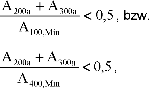
Die Erfindung sowie vorteilhafte Ausgestaltungen davon werden nachfolgend anhand von Ausführungsbeispielen näher erläutert, die in den Figuren der Zeichnung dargestellt sind. Gleiche bzw. gleichwirkende oder gleichartig fungierende Teile sind in allen Figuren mit denselben Bezugszeichen versehen; wenn es die Übersichtlichkeit erfordert oder es anderweitig sinnvoll erscheint, wird auf bereits erwähnte Bezugszeichen in nachfolgenden Figuren verzichtet. Weitere vorteilhafte Ausgestaltungen oder Weiterbildungen, insb. auch Kombinationen zunächst nur einzeln erläuterter Teilaspekte der Erfindung, ergeben sich ferner aus den Figuren der Zeichnung und/oder aus den Ansprüchen an sich.The invention and advantageous embodiments thereof are explained in more detail below with reference to exemplary embodiments, which are illustrated in the figures of the drawing. Identical or equivalent parts or identical parts are provided in all figures with the same reference numerals; if it requires the clarity or it appears otherwise useful, is omitted reference numerals already mentioned in subsequent figures. Further advantageous embodiments or developments, esp. Combinations initially only individually explained aspects of the invention will become apparent from the figures of the drawing and / or from the claims themselves.

Im einzelnen zeigen:In detail show:

1 schematisiert in einer Seitenansicht ein, insb. dem Messen wenigstens einer physikalischen Meßgröße eines in einer Rohrleitung strömenden Fluids dienliches, Fluidleitungssystem; 1 schematized in a side view, in particular the measurement of at least one physical quantity of fluid flowing in a pipeline fluid line system;

2 schematisiert in einer Seitenansicht ein weiteres Ausführungsbeispiel eines dem Messen wenigstens einer physikalischen Meßgröße dienlichen, insb. nämlich als vibronischer Meßwandler ausgebildeten, Fluidleitungssystems; 2 schematically shows a side view of a further embodiment of a fluid conduit system serving to measure at least one physical measurand, in particular a vibronic transducer;

3a, 3b, schematisiert verschiedene Strömungsquerschnitte von Fluidleitungen eines Fluidleitungssystems gemäß 1; und 3a . 3b schematically different flow cross-sections of fluid lines of a fluid conduit system according to 1 ; and

4 Verläufe von Strömungsquerschnitten von Fluidleitungen eines Fluidleitungssystems gemäß 1. 4 Curves of flow cross sections of fluid lines of a fluid line system according to 1 ,

In der 1 bzw. 2 ist schematisiert jeweils ein Ausführungsbeispiel eines dem Führen eines strömenden Fluids, beispielsweise nämlich einer Flüssigkeit, einem Gas oder einer Dispersion, dienliches Fluidleitungssystem gezeigt. Das Fluidleitungssystem ist jeweils im besonderen dafür eingerichtet, das – beispielsweise über ein angeschlossenes Zuleitungssegment einer Rohrleitung – herangeführte Fluid in wenigstens zwei Teilströme aufzuteilen, diese in einer Durchströmungsrichtung des Fluidleitungssystem weiter entlang zweier paralleler Strömungspfade zu führen und hernach nämliche Teilströme wieder zu einem gemeinsamen Fluidstrom zusammenzuführen und diesen wieder – beispielsweise an ein angeschlossenes Ableitungssegment der vorbezeichneten Rohrleitung – abzugeben. Nach einer weiteren Ausgestaltung der Erfindung ist das Fluidleitungssystem ferner auch dafür vorgesehen bzw. eingerichtet, zum Ermitteln von Meßwerten für wenigstens eine Meßgröße – beispielsweise nämlich einer Massendurchflußrate, eines Massendurchflusses, einer Volumendurchflußrate, eines Volumendurchflusses, einer Dichte, einer Viskosität oder einer Temperatur – eines zu transferierenden Fluids verwendet zu werden bzw. ein entsprechendes Meßsystem zu bilden. Bei dem zu transferierenden Fluid kann es sich beispielsweise um eine Flüssigkeit, ein Gas oder eine Dispersion handeln; ein mittels des erfindungsgemäßen Fluidleitungssystem zu transferierendes Fluid kann demnach beispielsweise ein verflüssigtes Gas, wie z. B. ein verflüssigten Erdgas (LNG), oder beispielsweise auch ein komprimiertes Gas, wie z. B. ein komprimiertes Erdgas (CNG), sein. Das Fluidleitungssystem kann demnach, wie u. a. auch in 2 angedeutet, beispielsweise auch integraler Bestandteil eines, beispielsweise vibronischen, Meßwandlers bzw. eines entsprechenden, beispielsweise auch als ein vorkonfektioniertes In-Line-Meßgerät ausgebildeten, Meßsystems sein.In the 1 respectively. 2 is shown schematically each an embodiment of a guiding a flowing fluid, for example, namely, a liquid, a gas or a dispersion, useful fluid conduit system. The fluid line system is in each case in particular adapted to divide the fluid introduced, for example via a connected supply segment of a pipeline, into at least two substreams, to guide it further along two parallel flow paths in a flow direction of the fluid line system and subsequently to merge the same substreams again into a common fluid flow and this again - for example, to a connected derivative segment of the aforementioned pipeline - leave. According to a further embodiment of the invention, the fluid conduit system is also provided or adapted for determining measured values for at least one measured quantity - for example a mass flow rate, a mass flow rate, a volumetric flow rate, a volumetric flow rate, a density, a viscosity or a temperature - one to be used to transfer fluid or to form a corresponding measurement system. The fluid to be transferred may be, for example, a liquid, a gas or a dispersion; a fluid to be transferred by means of the fluid conduit system according to the invention can therefore be used, for example, a liquefied gas, such. As a liquefied natural gas (LNG), or, for example, a compressed gas such. B. a compressed natural gas (CNG), be. The fluid line system can therefore, as, inter alia, in 2 indicated, for example, be an integral part of, for example, a vibronic transducer or a corresponding, for example, designed as a pre-assembled in-line measuring device, measuring system.

Das Fluidleitungssystem umfaßt eine – beispielsweise als Anschlußstutzen ausgebildete – erste Fluidleitung 100, eine – beispielsweise als starres und/oder zumindest abschnittsweise kreiszylindrisches Rohr ausgebildete – zweite Fluidleitung 200, eine – beispielsweise als starres und/oder zumindest abschnittsweise kreiszylindrisches Rohr ausgebildete und/oder zur Fluidleitung 200 baugleiche – dritte Fluidleitung 300 sowie eine – beispielsweise als Anschlußstutzen ausgebildete und/oder zur Fluidleitung 100 baugleiche – vierte Fluidleitung 400. Jede der vorbezeichneten Fluidleitungen 100, 200, 300, 400 weist jeweils ein von einer Wandung – beispielsweise aus einem Metall – umhülltes Lumen 100*, 200*, 300* bzw. 400* auf, wobei sich das Lumen 100* der Fluidleitung 100 von einer in einem ersten Leitungsende 100+ der Fluidleitung 100 verorteten ersten Strömungsöffnung 100a sowohl bis zu einer in einem zweiten Leitungsende 100# nämlicher ersten Fluidleitung 100 verorteten zweiten Strömungsöffnung 100b als auch bis zu einer von nämlicher zweiten Strömungsöffnung 100b beabstandet im zweiten Leitungsende 100# nämlicher ersten Fluidleitung 100 verorteten dritten Strömungsöffnung 100c, das Lumen 200* der Fluidleitung 200 von einer in einem ersten Leitungsende 200+ der Fluidleitung 200 verorteten ersten Strömungsöffnung 200a bis zu einer in einem zweiten Leitungsende 200# nämlicher Fluidleitung 200 verorteten zweiten Strömungsöffnung 200b, das Lumen 300* der Fluidleitung 300 von einer in einem ersten Leitungsende 300+ der Fluidleitung 300 verorteten ersten Strömungsöffnung 300a bis zu einer in einem zweiten Leitungsende 300# nämlicher Fluidleitung 300 verorteten zweiten Strömungsöffnung 300b bzw. das Lumen 400* der Fluidleitung 400 von einer in einem ersten Leitungsende 400+ der Fluidleitung 400 verorteten ersten Strömungsöffnung 400a sowohl bis zu einer in einem zweiten Leitungsende 400# nämlicher Fluidleitung 400 verorteten zweiten Strömungsöffnung 400b als auch bis zu einer von nämlicher zweiten Strömungsöffnung 400b beabstandet im zweiten Leitungsende 400# nämlicher vierten Fluidleitung 400 verorteten dritten Strömungsöffnung 400c erstrecken. Sowohl die Fluidleitung 200 als auch die Fluidleitung 300 sind mit deren jeweiligen ersten Leitungsende 200+ bzw. 300+ jeweils mit dem Leitungsende 100# der Fluidleitung 100 und mit deren jeweiligen zweiten Leitungsende 200# bzw. 300# jeweils mit dem Leitungsende 400# der Fluidleitung 400 verbunden; dies im besonderen in der Weise, daß sowohl das Lumen der Fluidleitung 200 als auch das Lumen der Fluidleitung 300 mit dem Lumen der Fluidleitung 100 bzw. dem Lumen der Fluidleitung 400 kommunizierten, bzw. daß die Strömungsöffnung 200a der Fluidleitung 200 in die Strömungsöffnung 100b der Fluidleitung 100 und die Strömungsöffnung 300a der Fluidleitung 300 in die Strömungsöffnung 100c der Fluidleitung 100 münden und/oder daß die Strömungsöffnung 200b der Fluidleitung 200 in die Strömungsöffnung 400b der Fluidleitung 400 und die Strömungsöffnung 300b der Fluidleitung 300 in die Strömungsöffnung 400c der Fluidleitung 400 münden. Die Strömungsöffnungen 200a, 200b, 300a, 300b, 100b, 100c, 400c, 400d können jeweils beispielsweise kreisförmig, halbkreisförmig oder – wie auch in 2a bzw. 2b angedeutet – ovalförmig ausgebildet sein. Nach einer weiteren Ausgestaltung der Erfindung sind die Strömungsöffnung 100a bzw. ein dadurch gebildeter einlaßseitiger Strömungsquerschnitt A100a der Fluidleitung 100 und/oder die Strömungsöffnung 100a bzw. ein dadurch gebildeter auslaßseitige Strömungsquerschnitt A400a der Fluidleitung 400 zudem kreisförmig ausgebildet. Das Lumen der zweiten und dritten Fluidleitungen 200, 300 kann jeweils zumindest abschnittsweise, insb. auch überwiegend, kreiszylindrisch ausgebildet sein. Darüberhinaus kann das Lumen der zweiten und dritten Fluidleitungen 200, 300 jeweils abschnittsweise auch kegel- bzw. konusförmig ausgebildet sein, beispielsweise jeweils in einem an die jeweilige Strömungsöffnung 200a, 200b, 300a bzw. 300b angrenzenden Übergangsbereich.The fluid line system comprises a - for example, designed as a connecting piece - the first fluid line 100 , a - formed for example as a rigid and / or at least partially circular cylindrical tube - second fluid line 200 , one - formed for example as a rigid and / or at least partially circular cylindrical tube and / or fluid line 200 identical - third fluid line 300 and a - formed for example as a connecting piece and / or to the fluid line 100 identical - fourth fluid line 400 , Each of the aforementioned fluid lines 100 . 200 . 300 . 400 each has one of a wall - for example, a metal - enveloped lumen 100 * . 200 * . 300 * respectively. 400 * on, with the lumen 100 * the fluid line 100 from one in a first line end 100+ the fluid line 100 located first flow opening 100a both up to one in a second line end 100 # same first fluid line 100 located second flow opening 100b as well as up to one of the same second flow opening 100b spaced in the second end of the line 100 # same first fluid line 100 located third flow opening 100c , the lumen 200 * the fluid line 200 from one in a first line end 200+ the fluid line 200 located first flow opening 200a up to one in a second line end 200 # the same fluid line 200 located second flow opening 200b , the lumen 300 * the fluid line 300 from one in a first line end 300+ the fluid line 300 located first flow opening 300a up to one in a second line end 300 # the same fluid line 300 located second flow opening 300b or the lumen 400 * the fluid line 400 from one in a first line end 400+ the fluid line 400 located first flow opening 400a both up to one in a second line end 400 # the same fluid line 400 located second flow opening 400b as well as up to one of the same second flow opening 400b spaced in the second end of the line 400 # the same fourth fluid line 400 located third flow opening 400c extend. Both the fluid line 200 as well as the fluid line 300 are with their respective first line end 200+ respectively. 300+ each with the cable end 100 # the fluid line 100 and with their respective second line end 200 # respectively. 300 # each with the cable end 400 # the fluid line 400 connected; this in particular in such a way that both the lumen of the fluid line 200 as well as the lumen of the fluid line 300 with the lumen of the fluid line 100 or the lumen of the fluid line 400 communicated, or that the flow opening 200a the fluid line 200 in the flow opening 100b the fluid line 100 and the flow opening 300a the fluid line 300 in the flow opening 100c the fluid line 100 open and / or that the flow opening 200b the fluid line 200 in the flow opening 400b the fluid line 400 and the flow opening 300b the fluid line 300 in the flow opening 400c the fluid line 400 lead. The flow openings 200a . 200b . 300a . 300b . 100b . 100c . 400c . 400d can each, for example, circular, semicircular or - as well as in 2a respectively. 2 B indicated - be oval shaped. According to a further embodiment of the invention, the flow opening 100a or an inlet-side flow cross-section A 100a of the fluid line formed thereby 100 and / or the flow opening 100a or an outlet-side flow cross-section A 400a of the fluid line formed thereby 400 also circular. The lumen of the second and third fluid lines 200 . 300 can in each case at least partially, esp. Also predominantly, be formed circular cylindrical. In addition, the lumen of the second and third fluid lines 200 . 300 in each case in sections, also cone-shaped or cone-shaped, for example, in each case in one of the respective flow opening 200a . 200b . 300a respectively. 300b adjacent transition area.

Die Wandung der Fluidleitungen 100, 200, 300, 400 können wie bei Fluidleitungssystemen der in Rede stehenden Art durchaus üblich zumindest anteilig aus einem – insb. zumindest hinsichtlich einer spezifischen thermischen Ausdehnung zum Material der jeweils anderen Fluidleitungen kompatiblen – Metall, beispielsweise nämlich Titan, Zirkonmium, einem Edelstahl oder einer Nickelbasislegierung, bestehen. Das Lumen der Fluidleitung 100 bzw. der der Fluidleitung 400, können zudem nach Art eines Lumens eines Sammelstücks jeweils im wesentlichen Y-förmig oder nach Art eines Lumens eines T-Stücks jeweils im wesentlichen T-förmig ausgebildet sein. Nicht zuletzt für den vorbeschriebenen Fall, daß das Fluidleitungssystem dafür vorgesehen ist, in den Verlauf einer Rohrleitung eingegliedert zu werden bzw. daß die ersten und/oder vierten Fluidleitungen 100, 400 als Anschlußstutzen ausgebildet sind, können – wie auch in 1 bzw. 2 schematisch dargestellt – das Leitungsende 100+ der Fluidleitung 100 bzw. die dort verortetet Strömungsöffnung 100a und/oder das Leitungsende 400+ der Fluidleitung 400 bzw. die dort verortetet Strömungsöffnung 400a zudem jeweils auch von einem zu einem an der vorbezeichneten Rohrleitung ggf. vorgesehenen Anschlußflansch kompatiblen Anschlußflansch F1 bzw. F2 gefaßt sein.The wall of the fluid lines 100 . 200 . 300 . 400 As with fluid line systems of the type in question, they may be at least partially composed of a metal, in particular titanium, zirconium, a stainless steel or a nickel-based alloy, at least with regard to a specific thermal expansion to the material of the respective other fluid lines. The lumen of the fluid line 100 or the fluid line 400 , In addition, in the manner of a lumen of a collecting piece may each be substantially Y-shaped or in the manner of a lumen of a T-piece in each case substantially T-shaped. Not least for the case described above, that the fluid line system is intended to be incorporated into the course of a pipeline or that the first and / or fourth fluid lines 100 . 400 are designed as connecting pieces, can - as well as in 1 respectively. 2 shown schematically - the cable end 100+ the fluid line 100 or the flow opening located there 100a and / or the cable end 400+ the fluid line 400 or the flow opening located there 400a In addition, each of a compatible to the above-mentioned pipe connection flange suitable flange F1 and F2 be taken.

Jede der beiden Fluidleitungen 200, 300 ist ferner so ausgebildet, daß sie entlang der im Fluidleitungssystem etablierten Strömungspfade bzw. in Durchströmungsrichtung des Fluidleitungssystems jeweils verschiedene – nämlich verschieden große und/oder verschieden geformte – Strömungsquerschnitte aufweist, derart, daß jede der Fluidleitungen 200, 300 jeweils einander benachbarte Strömungsquerschnitte mit voneinander abweichender Form und/oder voneinander abweichender Größe aufweist. Nach einer weiteren Ausgestaltung der Erfindung bilden hierbei die erste Strömungsöffnung 200a der Fluidleitung 200 einen – beispielsweise kreisförmigen, halbkreisförmigen oder ovalförmigen – einlaßseitigen Strömungsquerschnitt A200a nämlicher Fluidleitung 200 und die zweite Strömungsöffnung 200b der Fluidleitung 200 einen – beispielsweise kreisförmigen, halbkreisförmigen oder ovalförmigen – auslaßseitigen Strömungsquerschnitt A200b nämlicher Fluidleitung 200, die erste Strömungsöffnung 300a der Fluidleitung 300 einen Strömungsquerschnitt A300a nämlicher Fluidleitung 300 und die zweite Strömungsöffnung 300b der Fluidleitung 300 einen – beispielsweise kreisförmigen, halbkreisförmigen oder ovalförmigen – auslaßseitigen Strömungsquerschnitt A300b nämlicher Fluidleitung 300. Darüberhinaus sind nämliche Fluidleitungen 200, 300 des erfindungsgemäßen Fluidleitungssystems ferner so ausgestaltet, daß – wie auch in 1a schematisch dargestellt – jeweils ein jeweiliger größter Strömungsquerschnitt A200,Max bzw. A300,Max der jeweiligen Fluidleitung 200 bzw. 300 sowohl von deren jeweiligen ersten Leitungsende 200+ bzw. 300+ als auch von deren jeweiligen zweiten Leitungsende 200# bzw. 300# beabstandet ist.Each of the two fluid lines 200 . 300 is also designed so that they have along the established in the fluid conduit flow paths or in the flow direction of the fluid conduit system each different - namely differently sized and / or differently shaped - flow cross-sections, such that each of the fluid lines 200 . 300 each having adjacent flow cross-sections with divergent shape and / or different size. According to a further embodiment of the invention in this case form the first flow opening 200a the fluid line 200 a - for example, circular, semi-circular or oval - inlet-side flow cross-section A 200a nämlicher fluid line 200 and the second flow opening 200b the fluid line 200 a - for example, circular, semi-circular or oval - outlet-side flow cross section A 200b nämlicher fluid line 200 , the first flow opening 300a the fluid line 300 a flow cross-section A 300a nämlicher fluid line 300 and the second flow opening 300b the fluid line 300 a - for example, circular, semi-circular or oval - outlet-side flow cross-section A 300b nämlicher fluid line 300 , In addition, the same fluid lines 200 . 300 the fluid conduit system according to the invention further designed so that - as well as in 1a shown schematically - each a respective largest flow cross-section A 200, Max or A 300, Max the respective fluid line 200 respectively. 300 both from their respective first line end 200+ respectively. 300+ as well as from their respective second line end 200 # respectively. 300 # is spaced.

Jeder der vorbezeichneten Strömungsquerschnitte A200a, A300a, A200b, A300b der zweiten bzw. dritten Fluidleitung 200, 300 kann – wie bereits angedeutet – kreisförmig, halbkreisförmig oder – wie auch in 3a bzw. 3b schematisch dargestellt – beispielsweise ovalförmig ausgebildet sein, beispielsweise auch derart, daß nämliche Strömungsquerschnitte A200a, A300a, A200b, A300b jeweils gleich geformt und jeweils gleichgroß sind. Dementsprechend sind nach einer weiteren Ausgestaltung der Erfindung die Fluidleitung 200 und die Fluidleitung 300 so ausgebildet, daß deren Strömungsquerschnitte A200a, A300a, A200b bzw. A300b zumindest eine der Bedingungen: A200a = A300a, A200b = A300b, A200a = A200b bzw. A300a = A300b erfüllen. Nach einer weiteren Ausgestaltung der Erfindung ist das Lumen der Fluidleitung 200 zumindest abschnittsweise, insb. auch überwiegend, kreiszylindrisch ausgebildet, und ist zudem der größte Strömungsquerschnitt A200,Max der der Fluidleitung 200 in einem kreiszylindrischem Abschnitt nämlichen Lumens verortet und/oder ist das Lumen der Fluidleitung 300 zumindest abschnittsweise, insb. überwiegend, kreiszylindrisch ausgebildet und ist der größte Strömungsquerschnitt A300,Max der Fluidleitung 300 in einem kreiszylindrischem Abschnitt nämlichen Lumens verortet. Dementsprechend ist der größte Strömungsquerschnitt A200,Max der Fluidleitung 200 bzw. der größte Strömungsquerschnitt A300,Max der Fluidleitung 300 kreisförmig ausgebildet. Die zweiten und dritten Fluidleitungen 200, 300 können zudem so ausgebildet sein, daß der größte Strömungsquerschnitt A200,Max der Fluidleitung 200 und der größte Strömungsquerschnitt A300,Max der Fluidleitung 300 gleichgroß sind, nämlich insgesamt eine Bedingung: A200,Max = A300,Max erfüllen.Each of the aforementioned flow cross sections A 200a , A 300a , A 200b , A 300b of the second and third fluid line 200 . 300 can - as already indicated - circular, semicircular or - as well as in 3a respectively. 3b shown schematically - be formed, for example, oval-shaped, for example, such that the same flow cross-sections A 200a , A 300a , A 200b , A 300b each have the same shape and are the same size. Accordingly, according to a further embodiment of the invention, the fluid line 200 and the fluid line 300 such that their flow cross-sections A 200a , A 300a , A 200b and A 300b meet at least one of the conditions: A 200a = A 300a , A 200b = A 300b , A 200a = A 200b and A 300a = A 300b, respectively . According to a further embodiment of the invention, the lumen of the fluid line 200 at least in sections, esp. Also predominantly, circular cylindrical, and is also the largest flow area A 200, Max of the fluid line 200 located in a circular cylindrical portion of the same lumen and / or is the lumen of the fluid line 300 at least in sections, especially predominantly circular cylindrical and is the largest flow cross-section A 300, Max the fluid line 300 located in a circular cylindrical section of the same lumen. Accordingly, the largest flow area A 200, Max of the fluid line 200 or the largest flow cross section A 300, Max the fluid line 300 circular shaped. The second and third fluid lines 200 . 300 can also be designed so that the largest flow cross-section A 200, Max the fluid line 200 and the largest flow area A 300, Max of the fluid line 300 are equal in size, namely a total condition: A 200, Max = A 300, Max meet.

Wie bereits erwähnt, ist eine Neigung des vorbezeichneten Fluidleitungssystems – nicht zuletzt auch von dessen Fluidleitungen 200, 300 – zu Resonanzschwingungen, die durch im hindurchströmenden Fluid propagierendem Schall bzw. durch im hindurchströmenden Fluid etablierten stehenden Schallwellen induziert sind, im besonderen durch einen Verlauf von im Fluidleitungssystem in Durchströmungsrichtung ausgebildeten akustischen Wellen- bzw. Flußimpedanzen mitbestimmt. Nämlicher Verlauf der akustischen Wellenimpedanzen ist letztlich auch davon abhängig, in welchem Maße einander in Durchströmungsrichtung benachbarte Strömungsquerschnitte der Fluidleitungen hinsichtlich Größe und/oder Form voneinander abweichen. Durch weiterführende Untersuchungen konnten hierbei ein zwischen der ersten Fluidleitung 100 und den zweiten bzw. dritten Fluidleitungen 200, 300 verorteter einlaßseitiger Übergangsbereich bzw. ein zwischen der vierten Fluidleitung 400 und den zweiten bzw. dritten Fluidleitungen 200, 300 verorteter auslaßseitiger Übergangsbereich als für die Ausbildung stehender Schallwellen im Fluidleitungssystem besonders kritisch identifiziert werden. Zwecks Vermeidung von kritischen Impedanzsprüngen, nämlich von abrupten, gleichwohl stehende Schallwellen innerhalb der zweiten und dritten Fluidleitungen 200, 300 provozierenden Änderungen der akustischen Wellenimpedanzen des Fluidleitungssystems entlang von dessen Durchströmungsrichtung sind die erste Fluidleitung 100, die zweite Fluidleitung 200 und die dritte Fluidleitung 300 beim erfindungsgemäßen Fluidleitungssystem so ausgebildet, daß ein am Leitungsende 100# der Fluidleitung 100 verorteter, gleichwohl an die Strömungsöffnung 100b sowie die Strömungsöffnung 100c nämlicher Fluidleitung 100 angrenzender auslaßseitiger Strömungsquerschnitt A100,Min der Fluidleitung 100, der einlaßseitige Strömungsquerschnitt A200a der Fluidleitung 200 sowie der einlaßseitige Strömungsquerschnitt A300a der Fluidleitung 300 insgesamt eine Bedingung:

Figure DE102016109058A1_0028
erfüllen, und daß nämlicher auslaßseitige Strömungsquerschnitt A100,Min, der größte Strömungsquerschnitt A200,Max der Fluidleitung 200 sowie der größte Strömungsquerschnitt A300,Max der zweiten bzw. dritten Fluidleitung 200, 300 insgesamt eine Bedingung:
Figure DE102016109058A1_0029
erfüllen, bzw. sind die zweite Fluidleitung 200, die dritte Fluidleitung 300 und die vierte Fluidleitung 400 beim erfindungsgemäßen Fluidleitungssystem so ausgebildet, daß der auslaßseitige Strömungsquerschnitt A200b der Fluidleitung 200, der auslaßseitige Strömungsquerschnitt A300b der Fluidleitung 300 sowie ein an am Leitungsende 400+ der Fluidleitung 400 verorteter, gleichwohl an die Strömungsöffnung 400b sowie die Strömungsöffnung 400c nämlicher Fluidleitung 400 angrenzender einlaßseitiger Strömungsquerschnitt A400,Min der Fluidleitung 400 insgesamt eine Bedingung:
Figure DE102016109058A1_0030
erfüllen und daß der größte Strömungsquerschnitt A200,Max der Fluidleitung 200, der größte Strömungsquerschnitt A300,Max der Fluidleitung 300 sowie nämlicher einlaßseitige Strömungsquerschnitt A400,Min der Fluidleitung 400 insgesamt eine Bedingung:
Figure DE102016109058A1_0031
erfüllen.As already mentioned, an inclination of the aforementioned fluid line system - not least of its fluid lines 200 . 300 - To resonant vibrations, which are induced by propagating in the fluid flowing through sound or established in the fluid flowing stationary sound waves, in particular by a course of the fluid line system in the flow direction co-determined acoustic wave or Flußimpedanzen. The same course of the acoustic wave impedances ultimately also depends on the extent to which flow cross-sections of the fluid lines, which differ from one another in the flow direction, differ in size and / or shape from one another. By further investigations, one could between the first fluid line 100 and the second and third fluid lines, respectively 200 . 300 located inlet-side transition region or between the fourth fluid line 400 and the second and third fluid lines, respectively 200 . 300 localized outlet-side transition region be identified as critical for the formation of sound waves in the fluid line system particularly critical. In order to avoid critical impedance jumps, namely abrupt, nonetheless standing sound waves within the second and third fluid lines 200 . 300 provocative changes in the acoustic wave impedances of the fluid conduit system along the direction of its flow are the first fluid conduit 100 , the second fluid line 200 and the third fluid line 300 formed in the fluid conduit system according to the invention so that one at the end of the line 100 # the fluid line 100 located, but at the flow opening 100b as well as the flow opening 100c the same fluid line 100 adjacent outlet-side flow cross-section A 100, Min of the fluid line 100 , the inlet-side flow cross-section A 200a of the fluid line 200 and the inlet-side flow cross-section A 300a of the fluid line 300 total one condition:
Figure DE102016109058A1_0028
meet, and that nämlicher outlet-side flow area A 100, Min , the largest flow area A 200, Max the fluid line 200 and the largest flow cross section A 300, Max of the second and third fluid line 200 . 300 total one condition:
Figure DE102016109058A1_0029
meet, or are the second fluid line 200 , the third fluid line 300 and the fourth fluid line 400 formed in the fluid conduit system according to the invention so that the outlet-side flow cross-section A 200b of the fluid line 200 , the outlet-side flow cross-section A 300b of the fluid line 300 as well as on at the end of the line 400+ the fluid line 400 located, but at the flow opening 400b as well as the flow opening 400c the same fluid line 400 adjacent inlet-side flow cross section A 400, Min of the fluid line 400 total one condition:
Figure DE102016109058A1_0030
meet and that the largest flow area A 200, Max the fluid line 200 , the largest flow area A 300, Max of the fluid line 300 as well as the same inlet-side flow cross-section A 400, Min the fluid line 400 total one condition:
Figure DE102016109058A1_0031
fulfill.

Zur Vermeidung bzw. Reduzierung von potenziell Schall im hindurchströmenden Fluid induzierenden Störquellen innerhalb der vorbezeichneten ein- bzw. auslaßseitigen Übergangsbereiche ist nach einer weiteren Ausgestaltung der Erfindung das Lumen der Fluidleitung 200 abschnittsweise, nämlich in einem sich von deren einlaßseitigen Strömungsquerschnitt A200a in Richtung zu deren größtem Strömungsquerschnitt A200,Max erstreckenden ersten Übergangsbereich der Fluidleitung 200 und/oder in einem sich von deren auslaßseitigen Strömungsquerschnitt A200b in Richtung zu deren größtem Strömungsquerschnitt A200,Max erstreckenden zweiten Übergangsbereich der Fluidleitung 200, kegel- bzw. konusförmig ausgebildet, derart, daß aneinandergrenzende Strömungsquerschnitte A200,j der Fluidleitung 200, ausgehend von deren einlaßseitigen Strömungsquerschnitt A200a in eine Richtung zj + hin zu deren größtem Strömungsquerschnitt A200,Max kontinuierlich, beispielsweise nämlich linear oder – wie in 3c angedeutet – überproportional, zunehmen, bzw. daß aneinandergrenzende Strömungsquerschnitte A200,j der Fluidleitung 200, ausgehend von deren auslaßseitigen Strömungsquerschnitt A200b in eine Richtung zj hin zu deren größtem Strömungsquerschnitt A200,Max kontinuierlich- beispielsweise linear oder überproportional – zunehmen. Darüberhinaus ist nach einer weiteren Ausgestaltung das Lumen der Fluidleitung 300 abschnittsweise, nämlich in einem sich von deren einlaßseitigen Strömungsquerschnitt A300a in Richtung zu deren größtem Strömungsquerschnitt A300,Max erstreckenden ersten Übergangsbereich der Fluidleitung 300 und/oder in einem sich von deren auslaßseitigen Strömungsquerschnitt A300b in Richtung zu deren größtem Strömungsquerschnitt A300,Max erstreckenden zweiten Übergangsbereich der Fluidleitung 300, kegel- bzw. konusförmig ausgebildet ist, derart, daß aneinandergrenzende Strömungsquerschnitte A300,j der Fluidleitung 300, ausgehend von deren einlaßseitigen Strömungsquerschnitt A300a in Richtung zj + hin zu deren größtem Strömungsquerschnitt A300,Max kontinuierlich, beispielsweise linear oder überproportional, zunehmen bzw. derart, daß aneinandergrenzende Strömungsquerschnitte A300,j der Fluidleitung 300, ausgehend von deren auslaßseitigen Strömungsquerschnitt A300b in Richtung zj hin zu deren größtem Strömungsquerschnitt A300,Max kontinuierlich, insb. linear oder überproportional, zunehmen. Desweiteren können die Fluidleitungen 200, 300 in vorteilhafter Weise so ausgebildet sein, daß sowohl eine Länge L200a des ersten Übergangsbereichs der Fluidleitung 200 als auch eine Länge L200b des zweiten Übergangsbereichs der Fluidleitung 200 – gemessen als ein kürzester Abstand zwischen dem Strömungsquerschnitt A200a bzw. A200b und dem dazu jeweils am nähesten liegenden Strömungsquerschnitt A200,Max – eine der Bedingungen: L200a ≥ 0,5·(√A 200,Max – √A 200a) (5) bzw. L200b ≥ 0,5·(√A 200,Max – √A 200a) (6) und/oder eine der Bedingungen: L200a ≤ 2·(√A 200,Max – √A 200a) (7) bzw. L200b ≤ 0,5·(√A 200,Max – √A 200a) (8) erfüllt, bzw. daß sowohl eine Länge L300a des ersten Übergangsbereichs der Fluidleitung 300 als auch eine Länge L300b des zweiten Übergangsbereichs der Fluidleitung 300 – gemessen als ein kürzester Abstand zwischen dem Strömungsquerschnitt A300a bzw. A300b und dem dazu jeweils am nähesten liegenden Strömungsquerschnitt A300,Max – eine der Bedingungen: L300a ≥ 0,5·(√A 300,Max – √A 300a) (9) bzw. L300b ≥ 0,5·(√A 300,Max – √A 300a) (10) und/oder eine der Bedingungen: L300a ≤ 2·(√A 300,Max – √A 300a) (11) bzw. L300b ≤ 0,5·(√A 300,Max – √A 300a) (12) erfüllt. Die tatsächlich für das jeweilige Fluidleitungssystem jeweils optimalen Längen L200a, L200b, L300a, L300b können dann beispielsweise als ein Kompromiss zwischen einem für die angestrebte niedrige Anfälligkeit des Fluidleitungssystems ausreichend guten Verlauf der akustischen Wellenimpedanzen und einer für die ggf. angestrebte hohe Meßgenauigkeit des Fluidleitungssystems ausreichend großen Gesamtlänge der Fluidleitungen 200 bzw. 300 – gefunden werden.In order to avoid or reduce potentially noise in the fluid flowing through the fluid-inducing sources of interference within the aforementioned inlet or outlet-side transition regions, the lumen of the fluid conduit is according to a further embodiment of the invention 200 in sections, namely in a from the inlet-side flow cross-section A 200a in the direction of the largest flow cross-section A 200, Max extending first transition region of the fluid line 200 and / or in a second transition region of the fluid line extending from its outlet-side flow cross-section A 200b in the direction of its largest flow cross-section A 200, Max 200 , Conical or conical shaped, such that adjoining flow cross sections A 200, j of the fluid line 200 , starting from the inlet-side flow cross-section A 200a in a direction z j + toward the largest flow cross-section A 200, Max continuously, for example, linear or - as in 3c indicated - disproportionately, increase, or that contiguous flow cross sections A 200, j of the fluid line 200 , starting from the outlet side Flow cross-section A 200b in a direction z j - to the largest flow cross-section A 200, Max continuously - for example, linear or disproportionately - increase. Moreover, according to a further embodiment, the lumen of the fluid line 300 in sections, namely in a from the inlet-side flow cross-section A 300a in the direction of the largest flow cross-section A 300, Max extending first transition region of the fluid line 300 and / or in a second transition region of the fluid line extending from its outlet-side flow cross section A 300b in the direction of its largest flow cross section A 300, Max 300 , Conical or cone-shaped, in such a way that adjoining flow cross sections A 300, j of the fluid line 300 , starting from the inlet-side flow cross-section A 300a in the direction z j + toward the largest flow cross-section A 300, Max continuously, for example linearly or disproportionately, increase or such that contiguous flow cross sections A 300, j of the fluid line 300 , starting from the outlet-side flow cross-section A 300b in the direction z j - towards the largest flow cross-section A 300, Max continuously, esp. Linear or disproportionately increase. Furthermore, the fluid lines 200 . 300 be formed in an advantageous manner so that both a length L 200a of the first transition region of the fluid conduit 200 and a length L 200b of the second transition region of the fluid conduit 200 Measured as a shortest distance between the flow cross section A 200a or A 200b and the flow cross section A 200 closest thereto , Max - one of the conditions: L 200a ≥ 0.5 · (√ A 200, Max - √ A 200a ) (5) respectively. L 200b ≥ 0.5 · (√ A 200, Max - √ A 200a ) (6) and / or one of the conditions: L 200a ≤ 2 · (√ A 200, Max - √ A 200a ) (7) respectively. L 200b ≤ 0.5 · (√ A 200, Max - √ A 200a ) (8) fulfilled, or that both a length L 300a of the first transition region of the fluid line 300 and a length L 300b of the second transition region of the fluid conduit 300 Measured as a shortest distance between the flow cross section A 300a or A 300b and the flow cross section A 300 closest thereto , Max - one of the conditions: L 300a ≥ 0.5 · (√ A 300, Max - √ A 300a ) (9) respectively. L 300b ≥ 0.5 · (√ A 300, Max - √ A 300a ) (10) and / or one of the conditions: L 300a ≤ 2 · (√ A 300, Max - √ A 300a ) (11) respectively. L 300b ≤ 0.5 · (√ A 300, Max - √ A 300a ) (12) Fulfills. The actual lengths L 200a , L 200b , L 300a , L 300b which are actually respectively for the respective fluid line system can then be used, for example, as a compromise between a sufficiently good course of the acoustic wave impedances for the desired low susceptibility of the fluid line system and a possibly high level of measurement accuracy the fluid line system sufficiently large overall length of the fluid lines 200 respectively. 300 - being found.

Zur weiteren Verbesserung des vorbezeichneten Verlaufs der akustischen Wellen- bzw. Flußimpedanzen des Fluidleitungssystems sind nach einer weiteren Ausgestaltung der Erfindung die Fluidleitungen 100, 200 und 300 ferner so ausgebildet, daß der auslaßseitige Strömungsquerschnitt A100,Min der Fluidleitung 100, der größte Strömungsquerschnitt A200,Max der Fluidleitung 200 sowie der größte Strömungsquerschnitt A300,Max der Fluidleitung 300 insgesamt eine Bedingung:

Figure DE102016109058A1_0032
erfüllen, und/oder sind die Fluidleitungen 200, 300 und 400 ferner so ausgebildet, daß nämlicher größter Strömungsquerschnitt A200,Max, nämlicher größter Strömungsquerschnitt A300,Max sowie der einlaßseitige Strömungsquerschnitt A400,Min der Fluidleitung 400 insgesamt eine Bedingung:
Figure DE102016109058A1_0033
erfüllen; dies idealerweise so, daß für die vorbezeichneten Strömungsquerschnitte A200,Max, A300,Max, A100,Min bzw. A400,Min insgesamt zumindest näherungsweise gilt:
Figure DE102016109058A1_0034
Alternativ oder in Ergänzung dazu ist die Fluidleitung 200 ferner so ausgebildet, daß deren einlaßseitiger Strömungsquerschnitt A200a und deren größter Strömungsquerschnitt A200,Max eine Bedingung:
Figure DE102016109058A1_0035
erfüllen, und/oder daß deren auslaßseitiger Strömungsquerschnitt (A200b) und deren größter Strömungsquerschnitt (A200,Max) eine Bedingung:
Figure DE102016109058A1_0036
erfüllen, bzw. ist die Fluidleitung 300 so ausgebildet, daß deren einlaßseitiger Strömungsquerschnitt A300a und deren größter Strömungsquerschnitt A300,Max eine Bedingung:
Figure DE102016109058A1_0037
erfüllen, und/oder daß deren auslaßseitiger Strömungsquerschnitt A300b und deren größter Strömungsquerschnitt A300,Max eine Bedingung:
Figure DE102016109058A1_0038
erfüllen.To further improve the aforementioned course of the acoustic wave or flux impedances of the fluid conduit system according to a further embodiment of the invention, the fluid lines 100 . 200 and 300 further formed so that the outlet-side flow area A 100, Min of the fluid line 100 . the largest flow area A 200, Max of the fluid line 200 as well as the largest flow cross-section A 300, Max the fluid line 300 total one condition:
Figure DE102016109058A1_0032
meet, and / or are the fluid lines 200 . 300 and 400 Furthermore, designed so that nämlicher largest flow cross-section A 200, Max , nämlicher largest flow cross-section A 300, Max and the inlet-side flow cross-section A 400, Min the fluid line 400 total one condition:
Figure DE102016109058A1_0033
fulfill; this is ideally such that for the above-described flow cross-sections A 200, Max , A 300, Max , A 100, Min or A 400, Min total is at least approximately:
Figure DE102016109058A1_0034
Alternatively or in addition to this is the fluid line 200 further formed so that the inlet-side flow cross-section A 200a and the largest flow cross-section A 200, Max a condition:
Figure DE102016109058A1_0035
meet, and / or that the outlet-side flow cross-section (A 200b ) and the largest flow cross section (A 200, Max ) a condition:
Figure DE102016109058A1_0036
meet, or is the fluid line 300 designed such that its inlet-side flow cross section A 300a and the largest flow cross section A 300, Max a condition:
Figure DE102016109058A1_0037
meet, and / or that the outlet-side flow cross-section A 300b and the largest flow cross-section A 300, Max a condition:
Figure DE102016109058A1_0038
fulfill.

Wie u. a. auch in 1, 3a bzw. 3b jeweils angedeutet, können der auslaßseitige Strömungsquerschnitt A100,Min der Fluidleitung 100 bzw. der einlaßseitige Strömungsquerschnitt A400,Min der Fluidleitung 400 – wie bei Fluidleitungsssystemen der in Rede stehenden Art durchaus üblich – beispielsweise kreisförmig ausgebildet sein; falls erforderlich – etwa zwecks Bereitstellung eines weiteren, der Erfüllung der vorbezeichneten Bedingungen (1) und (2) bzw. (3) und (4) sowie ggf. auch der Bedingungen (5), (6), (7) bzw. (8) zuträglichen Freiheitgrades beim Design des Fluidleitungssystems – können die beiden Strömungsquerschnitte A100,Min, A400,Min aber auch nicht-kreisförmig, beispielsweise nämlich auch ovalförmig ausgebildet sein. Nach einer weiteren Ausgestaltung der Erfindung sind die Fluidleitungen 100, 400 ferner so ausgestaltet, daß der auslaßseitige Strömungsquerschnitt A100,Min der Fluidleitung 100 und der einlaßseitige Strömungsquerschnitt A400,Min der Fluidleitung 400 zudem insgesamt eine Bedingung: A100,Min = A400,Min erfüllen.Like, among others, in 1 . 3a respectively. 3b respectively indicated, the outlet-side flow cross-section A 100, Min of the fluid line 100 or the inlet-side flow cross section A 400, Min of the fluid line 400 - As in fluid line systems of the type in question quite common - be circular, for example; if necessary - for the purpose of providing another, the fulfillment of the above conditions (1) and (2) or (3) and (4) as well as possibly also the conditions (5), (6), (7) or ( 8) favorable degree of freedom in the design of the fluid line system - can the two flow cross sections A 100, Min , A 400, Min but also non-circular, for example, be formed also oval-shaped. According to a further embodiment of the invention, the fluid lines 100 . 400 further configured so that the outlet-side flow cross-section A 100, Min the fluid line 100 and the inlet-side flow area A 400, Min of the fluid line 400 also a total condition: A 100, Min = A 400, Min meet.

Um zu ermöglichen, daß das Fluidleitungssystem – wie bei solchen Fluidleitungssystemen durchaus üblich – in eine Rohrleitung mit einem Nennquerschnitt eingegliedert werden kann, der größer als der auslaßseitige Strömungsquerschnitt A100,Min der Fluidleitung 100, mithin größer als eine Summe A200a + A300a der Strömungsquerschnitte A200a, A300a ist, bzw. der größer als der einlaßseitige Strömungsquerschnitt A400,Min der Fluidleitung 400, mithin größer als eine Summe A200b + A300b der Strömungsquerschnitte A200b + A300b ist, ist nach einer weiteren Ausgestaltung der Erfindung ferner vorgesehen, daß die Fluidleitung 100 so ausgebildet ist, daß deren einlaßseitiger Strömungsquerschnitt A100a sowie deren auslaßseitiger Strömungsquerschnitt A100,Min insgesamt eine Bedingung:

Figure DE102016109058A1_0039
erfüllen, bzw. daß die Fluidleitung 400 so ausgebildet ist, daß deren einlaßseitiger Strömungsquerschnitt A400,Min sowie deren auslaßseitiger Strömungsquerschnitt A400a insgesamt eine Bedingung:
Figure DE102016109058A1_0040
erfüllen. Um zu vermeiden, daß durch das Fluidleitungssystem im hindurchströmenden Fluid ein zu hoher Druckabfall provoziert wird, ist nach einer weiteren Ausgestaltung der Erfindung ferner vorgesehen, daß durch die vorbezeichneten Strömungsquerschnitte A100a, A100,Min bzw. A400a, A400,Min desweiteren eine der folgenden Bedingungen:
Figure DE102016109058A1_0041
erfüllt ist. Die Fluidleitungen 100, 400 sind zudem vorzugsweise so ausgebildet, daß der einlaßseitige Strömungsquerschnitt A100a einen größten Strömungsquerschnitt A100,Max der Fluidleitung 100 bzw. daß der auslaßseitige Strömungsquerschnitt A400a einen größten Strömungsquerschnitt A400,Max der Fluidleitung 400 bildet. Desweiteren können die Fluidleitungen 100, 400 in vorteilhafter Weise so ausgebildet sein, daß eine Länge L100 der Fluidleitung 100 – gemessen als ein kürzester Abstand zwischen deren beiden Strömungsöffnungen 100a, 100b bzw. deren beiden Leitungsenden 100+, 100# – eine Bedingung: L100a ≥ 0,5·(√A 100a – √A 100,Min) (25) und/oder eine Bedingung: L100a ≤ 2·(√A 100a – √A 100,Min) (26) erfüllt, bzw. daß eine Länge L400 der Fluidleitung 400 – gemessen als ein kürzester Abstand zwischen deren beiden Strömungsöffnungen 400a, 400b bzw. deren beiden Leitungsenden 400+, 400# – eine Bedingung: L400a ≥ 0,5·(√A 400a – √A 400,Min) (27) und/oder eine Bedingung: L400a ≤ 2·(√A 400a – √A 400,Min) (28) erfüllt. Die tatsächlich für das jeweilige Fluidleitungssystem jeweils optimalen Längen L100, L400 können dann beispielsweise wiederum als ein Kompromiss zwischen einem für die angestrebte niedrige Anfälligkeit des Fluidleitungssystems ausreichend guten Verlauf der akustischen Wellenimpedanzen und einer durch bauliche Gegebenheiten am jeweiligen Einsatzort nämlichen Fluidleitungssystems vorgegeben Einbaulänge – gemessen als ein maximaler Abstand zwischen den beiden Strömungsöffnungen 100a, 400a bzw. den beiden Leitungsenden 100+, 400+ – gefunden werden.In order to allow the fluid line system - as is quite common in such fluid line systems - can be incorporated into a pipe with a nominal cross section which is greater than the outlet side flow area A 100, Min of the fluid line 100 , that is greater than a sum A 200a + A 300a of the flow cross-sections A 200a , A 300a , or which is greater than the inlet-side flow cross-section A 400, Min of the fluid line 400 , is therefore greater than a sum A 200b + A 300b of the flow cross-sections A 200b + A 300b is, according to a further embodiment of the invention further provided that the fluid line 100 is formed so that the inlet-side flow cross-section A 100a and the outlet-side flow cross section A 100, Min total one condition:
Figure DE102016109058A1_0039
fulfill, or that the fluid line 400 is formed so that the inlet-side flow cross-section A 400, Min and the outlet-side flow cross-section A 400 a total of one condition:
Figure DE102016109058A1_0040
fulfill. In order to avoid that too high a pressure drop is provoked by the fluid conduit system in the fluid flowing therethrough, according to a further embodiment of the invention is further provided that by the above flow cross sections A 100a , A 100, Min or A 400a , A 400, Min further one of the following conditions:
Figure DE102016109058A1_0041
is satisfied. The fluid lines 100 . 400 are also preferably formed so that the inlet-side flow cross-section A 100a has a largest flow cross-section A 100, Max the fluid line 100 or that the outlet-side flow cross section A 400a has a largest flow cross section A 400, Max of the fluid line 400 forms. Furthermore, the fluid lines 100 . 400 be advantageously designed so that a length L 100 of the fluid line 100 - Measured as a shortest distance between the two flow openings 100a . 100b or their two line ends 100+ . 100 # - One condition: L 100a ≥ 0.5 · (√ A 100a - √ A 100, Min ) (25) and / or a condition: L 100a ≤ 2 · (√ A 100a - √ A 100, Min ) (26) fulfilled, or that a length L 400 of the fluid line 400 - Measured as a shortest distance between the two flow openings 400a . 400b or their two line ends 400+ . 400 # - One condition: L 400a ≥ 0.5 · (√ A 400a - √ A 400, Min ) (27) and / or a condition: L 400a ≤ 2 · (√ A 400a - √ A 400, Min ) (28) Fulfills. The actual lengths L 100 , L 400 that are respectively respectively optimal for the respective fluid line system can then, for example, be set as a compromise between a sufficiently good course of the acoustic wave impedances for the desired low susceptibility of the fluid line system and a predetermined length of installation due to structural conditions at the respective site of use as a maximum distance between the two flow openings 100a . 400a or the two line ends 100+ . 400+ - being found.

Zur Verbesserung des vorbezeichneten Verlaufs der akustischen Wellen- bzw. Flußimpedanzen des Fluidleitungssystems auch in dem durch die Fluidleitung 100 gebildeten Einlaßbereich des Fluidleitungssystems bzw. dem durch die Fluidleitung 400 gebildeten Auslaßbereich des Fluidleitungssystems sind nach einer weiteren Ausgestaltung der Erfindung die Fluidleitungen 100 und/oder die Fluidleitungen 400 ferner so ausgebildet, daß das Lumen der Fluidleitung 100 bzw. der Fluidleitung 400 – wie auch in 1, 2 oder 4 schematisch dargestellt bzw. aus deren Zusammenschau ohne weiteres ersichtlich – zumindest abschnittsweise, beispielsweise auch überwiegend, kreiskegel- bzw. konusförmig ausgebildet ist; dies beispielsweise nämlich auch derart, daß der auslaßseitige Strömungsquerschnitt A100,Min der Fluidleitung 100 in einem kreiskegel- bzw. konusförmigem Abschnitt des Lumens nämlicher Fluidleitung 100 verortet ist und aneinandergrenzende Strömungsquerschnitte A100,i der Fluidleitung 100 – ausgehend von deren auslaßseitigen Strömungsquerschnitt A100,Min – in eine Richtung zi + hin zum Leitungsende 100+ nämlicher Fluidleitung 100 kontinuierlich zunehmen, beispielsweise gemäß einer Funktion:

Figure DE102016109058A1_0042
zunehmen bzw. daß der kleinste Strömungsquerschnitt A400,Min der Fluidleitung 400 in einem kreiskegel- bzw. konusförmigem Abschnitt des Lumens nämlicher Fluidleitung 400 verortet ist und aneinandergrenzende Strömungsquerschnitte A400,j der Fluidleitung 400 – ausgehend von deren einlaßseitigen Strömungsquerschnitt A400,Min – in eine Richtung zj + hin zu deren Leitungsende 400+ kontinuierlich und/oder gemäß einer Funktion:
Figure DE102016109058A1_0043
zunehmen.To improve the aforementioned course of the acoustic wave or Flußimpedanzen the fluid conduit system also in the through the fluid line 100 formed inlet region of the fluid conduit system or through the fluid line 400 formed outlet region of the fluid conduit system according to another embodiment of the invention, the fluid lines 100 and / or the fluid lines 400 further formed so that the lumen of the fluid conduit 100 or the fluid line 400 - as well as in 1 . 2 or 4 is shown schematically or from their synopsis readily apparent - is formed at least in sections, for example, predominantly, circular cone or cone-shaped; this is for example also such that the outlet-side flow cross section A 100, Min of the fluid line 100 in a circular cone or conical section of the lumen of the same fluid line 100 is located and contiguous flow cross sections A 100, i of the fluid line 100 - Starting from the outlet-side flow cross-section A 100, Min - in a direction z i + towards the end of the line 100+ the same fluid line 100 continuously increase, for example according to a function:
Figure DE102016109058A1_0042
increase or that the smallest flow cross-section A 400, Min the fluid line 400 in a circular cone or conical section of the lumen of the same fluid line 400 is located and contiguous flow cross sections A 400, j of the fluid line 400 - Starting from the inlet-side flow cross-section A 400, Min - in a direction z j + toward the end of the line 400+ continuously and / or according to a function:
Figure DE102016109058A1_0043
increase.

Das erfindungsgemäße Fluidleitungssystem kann, wie bereits mehrfach erwähnt bzw. nicht zuletzt auch in 2 dargestellt, u. a. auch Bestandteil eines dem Messen wenigstens einer Meßgröße – wie z. B. einer Dichte, einer Viskosität, eines Strömungsparameters, wie etwa einer Massendurchflußrate oder einer Volumendurchflußrate, und/oder einer Temperatur – eines strömenden Fluids dienlichen Meßsystems sein bzw. ein solches Meßsystem umfassen. Nämliches Meßsystem wiederum kann beispielsweise mittels eines – beispielsweise auch dem Generieren von von einer Massendurchflußrate des strömenden Fluids abhängigen Corioliskräften dienlichen – vibronischen Meßwandlers, etwa gemäß einer der eingangs erwähnten Patentanmeldungen EP-A 816 807 , US-A 2001/0037690 , US-A 2008/0184816 , US-A 48 23 613 , US-A 56 02 345 , US-A 57 96 011 , US-A 2011/0146416 , US-A 2011/0265580 , US-A 2012/0192658 , WO-A 90/15310 , WO-A 00/08423 , WO-A 2006/107297 , WO-A 2006/118557 , WO-A 2008/059262 , WO-A 2009/048457 , WO-A 2009/078880 , WO-A 2009/120223 , WO-A 2009/123632 , WO-A 2010/059157 , WO-A 2013/006171 oder WO-A 2013/070191 oder auch gemäß der eigenen, nicht vorveröffentlichten deutschen Patentanmeldung DE 10 2014 118 367.3 , gebildet bzw. ein mittels eines solchen vibronischen Meßwandlers gebildetes konventionelles Coriolis-Massenduchfluß-Meßgerät sein. Bei einem solchen Fluidleitungssystem kann es sich zudem beispielsweise auch um eine Übergabestelle für eichpflichtigen Güterverkehr, wie z. B. eine Zapfanlage für Kraftstoffe bzw. eine Übergabestelle, handeln.The fluid line system according to the invention can, as already mentioned several times or not least in 2 represented, inter alia, also part of a measuring at least one measured variable - such. A density, a viscosity, a flow parameter, such as a mass flow rate or volume flow rate, and / or a temperature of a flowing fluid of the measurement system or comprising such a measurement system. The same measuring system, in turn, can, for example, by means of a - for example, the generation of dependent on a mass flow rate of the flowing fluid Corioliskräfte vibronischen transducer, such as according to one of the aforementioned patent applications EP-A 816 807 . US-A 2001/0037690 . US-A 2008/0184816 . US-A 48 23 613 . US-A 56 02 345 . US Pat. No. 5,796,011 . US-A 2011/0146416 . US-A 2011/0265580 . US-A 2012/0192658 . WO-A 90/15310 . WO-A 00/08423 . WO-A 2006/107297 . WO-A 2006/118557 . WO-A 2008/059262 . WO-A 2009/048457 . WO-A 2009/078880 . WO-A 2009/120223 . WO-A 2009/123632 . WO-A 2010/059157 . WO-A 2013/006171 or WO-A 2013/070191 or according to the own, not previously published German patent application DE 10 2014 118 367.3 , formed or formed by means of such a vibronic transducer conventional Coriolis Massenduchfluß meter. In such a fluid line system, it may also, for example, to a transfer point for custody transfer, such. As a dispenser for fuels or a transfer point act.

Nach einer weiteren Ausgestaltung der Erfindung ist daher vorgesehen, daß die Fluidleitungen 100, 200, 300, 400 Bestandteil eines dem Generieren wenigstens eines mit der vorbezeichneten wenigstens einen Meßgröße korrespondierenden Meßsignals dienenden Meßwandlers, beispielsweise nämlich eines vibronischen Meßwandlers, sind. Die Fluidleitung 100 kann demnach beispielsweise auch mittels eines Verteilerstücks eines solchen Meßwandlers, beispielsweise also mittels eines Verteilerstücks eines vibronischen Meßwandlers und/oder eines Meßwandlers eines Coriolis-Massendurchfluß-Meßgeräts, gebildet sein bzw. kann ein solches Verteilerstück mittels der Fluidleitung 100 gebildet sein. Nämliches Verteilerstück kann beispielsweise nominell als eine dem Aufteilen eines zugeführten Fluidstroms in zwei parallele Teilströme dienliche Leitungsverzweigung des vorbezeichneten Meßwandlers eingerichtet sein; das Verteilerstück kann aber auch eine nominell dem Zusammenführen zweier parallele Fluidströme zu einem Gesamtstrom dienliche Leitungsvereinigung des vorbezeichneten Meßwandlers sein.According to a further embodiment of the invention it is therefore provided that the fluid lines 100 . 200 . 300 . 400 Component of a generating at least one of the aforementioned at least one measured variable corresponding measuring signal serving transducer, for example, namely, a vibronic transducer, are. The fluid line 100 Accordingly, for example, by means of a distributor of such a transducer, for example by means of a distributor of a vibronic transducer and / or a transducer of a Coriolis mass flow meter, be formed or such a manifold by means of the fluid line 100 be formed. For example, the same manifold may be nominally configured as a manifold of the aforementioned transducer useful for dividing a supplied fluid stream into two parallel substreams; but the manifold may also be a nominal union of merging two parallel fluid streams to a total current useful line union of the aforementioned transducer.

Dementsprechend kann auch die Fluidleitung 400 Bestandteil desselben Meßwandlers sein, beispielsweise nämlich mittels eines weiteren Verteilerstücks des Meßwandlers gebildet sein, das – komplementär zum anderen Verteilerstück – als eine dem Zusammenführen zweier parallele Fluidströme zu einem Gesamtstrom dienliche Leitungsvereinigung bzw. als eine dem Aufteilen eines zugeführten Fluidstroms in zwei parallele Teilströme dienliche Leitungsverzweigung eingerichtet ist. Accordingly, the fluid line 400 Be part of the same transducer, for example, be formed by means of another manifold of the transducer, the - complementary to the other manifold - serving as merging two parallel fluid streams into a total flow line union or as dividing a supplied fluid flow in two parallel streams useful line branching is set up.

Dementsprechend umfaßt das Fluidleitungssystem, wie auch 2 schematisch dargestellt, nach einer weiteren Ausgestaltung der Erfindung wenigstens einen ersten Sensor 51 zum Erzeugen wenigstens eines mit einer Meßgröße x eines im Fluidleitungssystem geführten Fluids korrespondierenden, nämlich wenigsten eines von nämlicher Meßgröße abhängigen Signalparameter aufweisenden – insb. elektrischen bzw. analogen – ersten Meßsignals s1. Bei der wenigstens einen Meßgröße x kann es sich, wie bereits erwähnt, beispielsweise um eine Dichte, eine Viskosität oder eine Temperatur des ggf. auch strömen gelassenen Fluids handeln. Nämliche Meßgröße x kann aber beispielsweise auch ein Strömungsparameter, wie etwa eine Massendurchflußrate oder einer Volumendurchflußrate, sein. Als ein von der Meßgröße abhängiger Signalparameter wiederum kann beispielsweise ein von der wenigstens einen Meßgröße abhängiger Signalpegel, eine von nämlicher Meßgröße abhängige Signalfrequenz und/oder ein von nämlicher Meßgröße abhängiger Phasenwinkel des Meßsignals dienen. Der Sensor 51 kann, wie in 2 angedeutet, außerhalb der Fluidleitungen 200, 300 gleichwohl in der Nähe der Fluidleitung 200 und/oder in der Nähe der Fluidleitung 300 plaziert sein, beispielsweise auch derart, daß der Sensor 51 zumindest an der Fluidleitung 200 bzw. sowohl an der Fluidleitung 200 als auch an der Fluidleitung 300 angebracht ist.Accordingly, the fluid conduit system includes as well 2 shown schematically, according to a further embodiment of the invention, at least a first sensor 51 for producing at least one first measurement signal s1 corresponding in particular to a measured quantity x of a fluid conducted in the fluid line system, namely at least one signal parameter dependent on the same measured variable, in particular electric or analogue. As already mentioned, the at least one measured variable x may be, for example, a density, a viscosity or a temperature of the fluid possibly also flowed. The same measurand x, however, may also be, for example, a flow parameter, such as a mass flow rate or a volumetric flow rate. As a dependent of the measured variable signal parameter turn, for example, depending on the at least one measured variable signal level, a signal of the same size dependent signal frequency and / or a dependent of nämlicher measured variable phase angle of the measuring signal are used. The sensor 51 can, as in 2 indicated, outside the fluid lines 200 . 300 nevertheless in the vicinity of the fluid line 200 and / or near the fluid line 300 be placed, for example, such that the sensor 51 at least on the fluid line 200 or both on the fluid line 200 as well as on the fluid line 300 is appropriate.

Für den bereits erwähnten Fall, daß die Fluidleitung 200 Bestandteil eines vibronischen Meßwandlers sind, ist nach einer weiteren Ausgestaltung der Erfindung zumindest die Fluidleitung 200 dafür eingerichtet, von Fluid durchströmt und währenddessen vibrieren gelassen zu werden. Darüberhinaus kann auch die Fluidleitung 300 dafür eingerichtet sein, beispielsweise nämlich für den Fall, daß sowohl die Fluidleitung 200 als auch die Fluidleitung 300 Bestandteil des vorbezeichneten vibronischen Meßwandlers sind, von Fluid durchströmt und währenddessen vibrieren gelassen zu werden; dies beispielsweise auch in der Weise, daß die beiden Fluidleitungen 200, 300 simultan von Fluid durchströmt und/oder während dessen simultan, insb. nämlich gegengleich, vibrieren gelassen werden Dementsprechend kann das Fluidleitungssystem nach einer weiteren Ausgestaltung der Erfindung ferner wenigstens einen, insb. elektromechanischen bzw. elektrodynamischen, Schwingungserreger 41 zum Anregen bzw. Aufrechterhalten mechanischer Schwingungen, beispielsweise nämlich Biegeschwingungen, zumindest der Fluidleitung 200 bzw. zum Anregen und/oder Aufrechterhalten mechanischer Schwingungen sowohl der Fluidleitung 200 als auch der Fluidleitung 300 umfassen. Desweiteren kann es sich im vorbezeichneten Fall bei dem Sensor 51 um einen, beispielsweise elektrodynamischen und/oder Schwingungsbewegungen der beiden Fluidleitungen 200, 300 differenziell erfassenden, Schwingungssensor handeln. Nicht zuletzt für den erwähnten Fall, daß das Fluidleitungssystem dafür vorgesehen ist, basierend auf im strömenden Fluid generierten Corioliskräften eine Massendurchflußrate zu messen, kann das Fluidleitungssystem zusätzlich zum Sensor 51 zudem auch wenigstens einen zweiten Sensor 52 zum Erzeugen wenigstens eines mit der Meßgröße korrespondierenden – insb. elektrischen und/oder analogen – zweiten Meßsignals s2 aufweisen. Nämlicher Sensor 52 kann baugleich wie der Sensor 51 und/oder und in gleichem Abstand wie der Sensor 51 von der Fluidleitung 200 bzw. den Fluidleitungen 200, 300 entfernt positioniert sein. Alternativ oder in Ergänzung können die Sensoren 51, 52 symmetrisch bezüglich des Schwingungserregers 41 positioniert sein, beispielsweise auch derart, daß, wie in 2 angedeutet und wie bei vibronischen Meßwandlern der vorbezeichneten Art durchaus üblich, der Sensor 52 von der Fluidleitung 100 weiter entfernt ist als der Sensor 51 bzw. umgekehrt der Sensor 51 von der Fluidleitung 400 weiter entfernt ist als der Sensor 52 und/oder derart, daß der Sensor 51 gleichweit von der Fluidleitung 100 entfernt ist wie der Sensor 52 von der Fluidleitung 400.For the already mentioned case, that the fluid line 200 Component of a vibronic transducer, according to a further embodiment of the invention, at least the fluid line 200 adapted to be traversed by fluid and vibrated while it is. In addition, also the fluid line 300 be set up for, for example, in the event that both the fluid line 200 as well as the fluid line 300 Part of the aforementioned vibronic transducer are to be traversed by fluid and vibrated while; This, for example, in such a way that the two fluid lines 200 . 300 Accordingly, the fluid conduit system according to a further embodiment of the invention further comprises at least one, esp. Electromechanical or electrodynamic, vibration exciter 41 for exciting or maintaining mechanical vibrations, for example bending vibrations, at least of the fluid line 200 or for exciting and / or maintaining mechanical vibrations of both the fluid line 200 as well as the fluid line 300 include. Furthermore, it may be the case in the case of the sensor 51 one, for example electrodynamic and / or oscillatory movements of the two fluid lines 200 . 300 act differentially detecting, vibration sensor. Not least in the case mentioned that the fluid conduit system is intended to measure a mass flow rate based on Coriolis forces generated in the flowing fluid, the fluid conduit system may be in addition to the sensor 51 also at least one second sensor 52 for generating at least one corresponding to the measured variable - esp. Electric and / or analog - second measuring signal s2. Same sensor 52 can be identical to the sensor 51 and / or equidistant to the sensor 51 from the fluid line 200 or the fluid lines 200 . 300 be positioned remotely. Alternatively or in addition, the sensors 51 . 52 symmetric with respect to the vibration exciter 41 be positioned, for example, such that, as in 2 indicated and quite common, as in vibronic transducers of the aforementioned type, the sensor 52 from the fluid line 100 farther away than the sensor 51 or vice versa, the sensor 51 from the fluid line 400 farther away than the sensor 52 and / or such that the sensor 51 equidistant from the fluid line 100 removed is like the sensor 52 from the fluid line 400 ,

Zwecks Verarbeitung bzw. Auswertung des wenigstens einen Meßsignals s1 kann das Fluidleitungssystem ferner eine mit dem Sensor 51 bzw. mit den Sensoren 51, 52 elektrisch gekoppelte, beispielsweise mittels wenigstens eines Mikroprozessors und/oder eines digitalen Signalprozessors (DSP) gebildete, Meß- und Betriebselektronik 500 umfassen, die – wie auch in 2 schematisch dargestellt – in vorteilhafter Weise wiederum in einem in ausreichendem Maße staub- und wasserdichten bzw. schlag- und explosionsfesten Schutzgehäuse 5000 untergebracht sein kann. Im besonderen kann die Meß- und Betriebselektronik 500 ferner dafür eingerichtet sein, das wenigstens eines Meßsignal s1 bzw. die Meßsignale s1, s2 zu verarbeiten, insb. nämlich mittels des Meßsignals s1 Meßwerte X für die wenigstens eine Meßgröße x zu ermitteln. Für den vorbezeichneten Fall, daß das Fluidleitungssystem mit wenigstens einem Schwingungserreger 41 ausgerüstet ist, kann die Meß- und Betriebselektronik 500 zudem mit nämlichem Schwingungserreger 41 elektrisch gekoppelt sein. Nach einer weiteren Ausgestaltung der Erfindung ist die Meß- und Betriebselektronik 500 ferner dafür eingerichtet, ein elektrische Anregungssignal e1 in den vorbezeichneten Schwingungserreger 41 einzuspeisen, und ist der Schwingungserreger 41 zudem dafür eingerichtet, mittels des Anregungssignals e1 eingespeiste elektrische Leistung in mechanische Schwingungen zumindest der Fluidleitung 200 bzw. in mechanische Schwingungen sowohl der Fluidleitung 200 als auch der Fluidleitung 300 bewirkende mechanische Leistung zu wandeln.For the purpose of processing or evaluating the at least one measuring signal s1, the fluid line system can also have one with the sensor 51 or with the sensors 51 . 52 electrically coupled, for example by means of at least one microprocessor and / or a digital signal processor (DSP) formed, measuring and operating electronics 500 include - as well as in 2 schematically illustrated - in turn advantageously in a sufficiently dustproof and watertight or shock and explosion proof protective housing 5000 can be accommodated. In particular, the measuring and operating electronics 500 furthermore be set up to process the at least one measuring signal s1 or the measuring signals s1, s2, in particular to determine measured values X for the at least one measured variable x by means of the measuring signal s1. For the aforementioned case, that the fluid line system with at least one vibration exciter 41 equipped, can the measuring and operating electronics 500 in addition with namely vibration exciter 41 be electrically coupled. According to a further embodiment of the invention, the measuring and operating electronics 500 further adapted to an electrical excitation signal e1 in the aforementioned vibration exciter 41 feed, and is the vibration generator 41 also set up by means of the excitation signal e1 fed electrical power into mechanical vibrations of at least the fluid line 200 or in mechanical vibrations of both the fluid line 200 as well as the fluid line 300 transforming mechanical power.

Nicht zuletzt für den erwähnten Fall, daß das Fluidleitungssystem als Bestandteil eines Meßsystems ausgebildet ist, kann das Fluidleitungssystem, wie auch in 2 schematisch dargestellt, ferner ein Schutzgehäuse 1000 für die Fluidleitungen 200, 300 umfassen. Das Schutzgehäuse 1000 weist eine von einer Wandung umhüllte Kavität auf, innerhalb der die Fluidleitung 200 und zumindest die Fluidleitung 300 plaziert sind. Nicht zuletzt zwecks Bildung eines in ausreichendem Maße verwindungs- und biegesteifen bzw. schlag- und druckfesten Schutzgehäuses kann dessen Wandung beispielsweise aus einem Metall, etwa einem Edelstahl, hergestellt und/oder zumindest teilweise hohlzylindrisch ausgebildet sein. Wie in ferner 2 angedeutet, kann zudem ein erstes Gehäuseende 1000+ des Schutzgehäuses 1000 mittels der Fluidleitung 100 gebildet sein, etwa derart, daß die Fluidleitung 100 integraler Bestandteil des Schutzgehäuses ist und/oder daß das Schutzgehäuse 1000 eine die vorbezeichnete Kavität seitlich begrenzende Seitenwand aufweist, die seitlich an der Fluidleitung 100 fixiert bzw. stoffschlüssig mit dieser verbunden ist. Darüberhinaus kann zudem auch ein zweites Gehäuseende 1000# nämlichen Schutzgehäuses 1000 mittels der Fluidleitung 400 gebildet sein, beispielsweise auch so, daß sowohl die Fluidleitung 100 als auch die Fluidleitung 400 jeweils integraler Bestandteil des Schutzgehäuses ist bzw. daß das Schutzgehäuse 1000 eine die Kavität seitlich begrenzende Seitenwand aufweist, die seitlich sowohl an der Fluidleitung 100 als auch an der Fluidleitung 400 fixiert bzw. stoffschlüssig mit der der ersten Fluidleitung verbunden ist.Not least for the case mentioned that the fluid line system is formed as part of a measuring system, the fluid line system, as well as in 2 shown schematically, further a protective housing 1000 for the fluid lines 200 . 300 include. The protective housing 1000 has a cavity enclosed by a wall, within which the fluid conduit 200 and at least the fluid line 300 are placed. Not least for the purpose of forming a sufficiently warp resistant and rigid or impact and pressure resistant protective housing whose wall can be made for example of a metal, such as a stainless steel, and / or at least partially hollow cylindrical. As in distant 2 indicated, in addition, a first housing end 1000+ of the protective housing 1000 by means of the fluid line 100 be formed, such that the fluid line 100 is an integral part of the protective housing and / or that the protective housing 1000 a side wall defining the aforementioned cavity laterally, the side of the fluid line 100 fixed or materially connected to this. In addition, also a second housing end 1000 # the same protective housing 1000 by means of the fluid line 400 be formed, for example, so that both the fluid line 100 as well as the fluid line 400 each integral part of the protective housing or that the protective housing 1000 a side wall delimiting the cavity, which laterally on both the fluid line 100 as well as on the fluid line 400 fixed or cohesively connected to the first fluid line.

ZITATE ENTHALTEN IN DER BESCHREIBUNG QUOTES INCLUDE IN THE DESCRIPTION

Diese Liste der vom Anmelder aufgeführten Dokumente wurde automatisiert erzeugt und ist ausschließlich zur besseren Information des Lesers aufgenommen. Die Liste ist nicht Bestandteil der deutschen Patent- bzw. Gebrauchsmusteranmeldung. Das DPMA übernimmt keinerlei Haftung für etwaige Fehler oder Auslassungen.This list of the documents listed by the applicant has been generated automatically and is included solely for the better information of the reader. The list is not part of the German patent or utility model application. The DPMA assumes no liability for any errors or omissions.

Zitierte PatentliteraturCited patent literature

  • EP 816807 A [0002, 0075] EP 816807 A [0002, 0075]
  • US 2001/0037690 A [0002, 0075] US 2001/0037690 A [0002, 0075]
  • US 2008/0184816 A [0002, 0075] US 2008/0184816 A [0002, 0075]
  • US 2011/0161017 A [0002] US 2011/0161017 A [0002]
  • US 2011/0154912 A [0002] US 2011/0154912 A [0002]
  • US 2011/0161018 A [0002] US 2011/0161018 A [0002]
  • US 2011/0146416 A [0002, 0075] US 2011/0146416 A [0002, 0075]
  • US 2012/0167697 A [0002] US 2012/0167697 A [0002]
  • US 2015/0082916 A [0002] US 2015/0082916 A [0002]
  • US 4801897 A [0002, 0005] US 4801897 A [0002, 0005]
  • US 4823613 A [0002, 0075] US 4823613 A [0002, 0075]
  • US 5602345 A [0002, 0075] US 5602345 A [0002, 0075]
  • US 5796011 A [0002, 0075] US 5796011 A [0002, 0075]
  • WO 90/15310 A [0002, 0075] WO 90/15310 A [0002, 0075]
  • WO 00/08423 A [0002, 0075] WO 00/08423 A [0002, 0075]
  • WO 2006/107297 A [0002, 0075] WO 2006/107297 A [0002, 0075]
  • WO 2006/118557 A [0002, 0075] WO 2006/118557 A [0002, 0075]
  • WO 2008/059262 A [0002, 0075] WO 2008/059262 A [0002, 0075]
  • WO 2009/048457 A [0002, 0075] WO 2009/048457 A [0002, 0075]
  • WO 2009/078880 A [0002, 0075] WO 2009/078880 A [0002, 0075]
  • WO 2009/120223 A [0002, 0075] WO 2009/120223 A [0002, 0075]
  • WO 2009/123632 A [0002, 0075] WO 2009/123632 A [0002, 0075]
  • WO 2010/059157 A [0002, 0075] WO 2010/059157 A [0002, 0075]
  • WO 2012/170020 A [0002] WO 2012/170020 A [0002]
  • WO 2013/006171 A [0002, 0075] WO 2013/006171 A [0002, 0075]
  • WO 2013/070191 A [0002, 0075] WO 2013/070191 A [0002, 0075]
  • WO 2015/085025 A [0002] WO 2015/085025 A [0002]
  • DE 102015118864 [0002] DE 102015118864 [0002]
  • US 2011/0265580 A [0075] US 2011/0265580 A [0075]
  • US 2012/0192658 A [0075] US 2012/0192658 A [0075]
  • DE 102014118367 [0075] DE 102014118367 [0075]

Claims (31)

Fluidleitungssystem, umfassend: – eine, insb. als Anschlußstutzen und/oder als Leitungsverzweigung ausgebildete, erste Fluidleitung (100) mit einem von einer Wandung, insb. aus einem Metall, umhüllten, sich von einer in einem, insb. von einem Anschlußflansch gefaßten, ersten Leitungsende (100+) der ersten Fluidleitung (100) verorteten, insb. kreisförmigen, ersten Strömungsöffnung (100a) sowohl bis zu einer in einem zweiten Leitungsende (100#) nämlicher ersten Fluidleitung (100) verorteten, insb. kreisförmigen, halbkreisförmigen oder ovalförmigen, zweiten Strömungsöffnung (100b) als auch bis zu einer von nämlicher zweiten Strömungsöffnung (100b) beabstandet im zweiten Leitungsende (100#) nämlicher ersten Fluidleitung (100) verorteten, insb. kreisförmigen, halbkreisförmigen oder ovalförmigen, dritten Strömungsöffnung (100c) erstreckenden Lumen (100*); – eine, insb. als starres und/oder zumindest abschnittsweise kreiszylindrisches Rohr ausgebildete, zweite Fluidleitung (200) mit einem von einer Wandung, insb. aus einem Metall, umhüllten, sich von einer in einem ersten Leitungsende (200+) der zweiten Fluidleitung verorteten, insb. kreisförmigen, halbkreisförmigen oder ovalförmigen, ersten Strömungsöffnung (200a) bis zu einer in einem zweiten Leitungsende (200#) nämlicher zweiten Fluidleitung (200) verorteten, insb. kreisförmigen, halbkreisförmigen oder ovalförmigen, zweiten Strömungsöffnung (200b) erstreckenden Lumen (200*), derart, daß ein größter Strömungsquerschnitt (A200,Max) der zweiten Fluidleitung (200) sowohl von deren ersten Leitungsende (200+) als auch von deren zweiten Leitungsende (200#) beabstandet ist; – wenigstens eine, insb. als starres und/oder zumindest abschnittsweise kreiszylindrisches Rohr ausgebildete und/oder zur zweiten Fluidleitung baugleiche, dritte Fluidleitung (300) mit einem von einer Wandung, insb. aus einem Metall, umhüllten, sich von einer in einem ersten Leitungsende (300+) der dritten Fluidleitung verorteten, insb. kreisförmigen, halbkreisförmigen oder ovalförmigen, ersten Strömungsöffnung (300a) bis zu einer in einem zweiten Leitungsende (300#) nämlicher dritten Fluidleitung (300) verorteten, insb. kreisförmigen, halbkreisförmigen oder ovalförmigen, zweiten Strömungsöffnung (300b) erstreckenden Lumen (300*), derart, daß ein größter Strömungsquerschnitt (A300,Max) der dritten Fluidleitung (300) sowohl von deren ersten Leitungsende (300+) als auch von deren zweiten Leitungsende (300#) beabstandet ist; – sowie eine, insb. zur ersten Fluidleitung baugleiche und/oder als Anschlußstutzen ausgebildete und/oder als Leitungsvereinigung dienliche, vierte Fluidleitung (400) mit einem von einer Wandung, insb. aus einem Metall, umhüllten, sich von einer in einem, insb. von einem Anschlußflansch gefaßten, ersten Leitungsende (400+) der vierten Fluidleitung (400) verorteten, insb. kreisförmigen, ersten Strömungsöffnung (400a) sowohl bis zu einer in einem zweiten Leitungsende (400#) nämlicher vierten Fluidleitung (400) verorteten, insb. kreisförmigen, halbkreisförmigen oder ovalförmigen, zweiten Strömungsöffnung (400b) als auch bis zu einer von nämlicher zweiten Strömungsöffnung beabstandet im zweiten Leitungsende (400#) nämlicher vierten Fluidleitung (400) verorteten, insb. kreisförmigen, halbkreisförmigen oder ovalförmigen, dritten Strömungsöffnung (400c) erstreckenden Lumen (400*); – wobei sowohl die zweite Fluidleitung (200) mit deren ersten Leitungsende (200+) als auch die dritte Fluidleitung (300) mit deren ersten Leitungsende (300+) jeweils mit dem zweiten Leitungsende (100#) der ersten Fluidleitung (100) verbunden sind, insb. derart, daß sowohl das Lumen der zweiten Fluidleitung (200) als auch das Lumen der dritten Fluidleitung (300) mit dem Lumen der ersten Fluidleitung (100) kommunizieren und/oder derart, daß die erste Strömungsöffnung (200a) der zweiten Fluidleitung (200) in die zweite Strömungsöffnung (100b) der ersten Fluidleitung (100) und die erste Strömungsöffnung (300a) der dritten Fluidleitung (300) in die dritte Strömungsöffnung (100c) der ersten Fluidleitung (100) münden; – wobei sowohl die zweite Fluidleitung (200) mit deren zweiten Leitungsende (200#) als auch die dritte Fluidleitung (300) mit deren zweiten Leitungsende (300#) jeweils mit dem zweiten Leitungsende (400#) der vierten Fluidleitung (400) verbunden sind, insb. derart, daß sowohl das Lumen (200*) der zweiten Fluidleitung (200) als auch das Lumen (300*) der dritten Fluidleitung (300) mit dem Lumen der vierten Fluidleitung (400) kommuniziert und/oder derart, daß die zweite Strömungsöffnung (200b) der zweiten Fluidleitung (200) in die zweite Strömungsöffnung (400b) der vierten Fluidleitung (400) und die zweite Strömungsöffnung (300b) der dritten Fluidleitung in die dritte Strömungsöffnung (400c) der vierten Fluidleitung (400) münden; – wobei die erste Strömungsöffnung (200a) der zweiten Fluidleitung (200) einen, insb. kreisförmigen, halbkreisförmigen oder ovalförmigen, einlaßseitigen Strömungsquerschnitt (A200a) nämlicher Fluidleitung (200) und die zweite Strömungsöffnung (200b) der zweiten Fluidleitung (200) einen, insb. kreisförmigen, halbkreisförmigen oder ovalförmigen, auslaßseitigen Strömungsquerschnitt (A200b) nämlicher Fluidleitung (200) bilden; und – wobei die erste Strömungsöffnung (300a) der dritten Fluidleitung (300) einen, insb. kreisförmigen, halbkreisförmigen oder ovalförmigen, einlaßseitigen Strömungsquerschnitt (A300a) nämlicher Fluidleitung (300) und die zweite Strömungsöffnung (300b) der dritten Fluidleitung (300) einen, insb. kreisförmigen, halbkreisförmigen oder ovalförmigen, auslaßseitigen Strömungsquerschnitt (A300b) nämlicher Fluidleitung (300) bilden; – wobei die erste Fluidleitung (100), die zweite Fluidleitung (200) und die dritte Fluidleitung (300) so ausgebildet sind, daß – daß ein am zweiten Leitungsende (100#) der ersten Fluidleitung (100) verorteter, gleichwohl an die zweite Strömungsöffnung (100b) sowie die dritte Strömungsöffnung (100c) nämlicher Fluidleitung (100) angrenzender auslaßseitiger Strömungsquerschnitt (A100,Min) der ersten Fluidleitung (100), der einlaßseitige Strömungsquerschnitt (A200a) der zweiten Fluidleitung (200) sowie der einlaßseitige Strömungsquerschnitt (A300a) der dritten Fluidleitung (300) insgesamt eine Bedingung:
Figure DE102016109058A1_0044
erfüllen – und daß nämlicher auslaßseitige Strömungsquerschnitt (A100,Min) der ersten Fluidleitung (100), der größte Strömungsquerschnitt (A200,Max) der zweiten Fluidleitung (200) sowie der größte Strömungsquerschnitt (A300,Max) der dritten Fluidleitung (300) insgesamt eine Bedingung:
Figure DE102016109058A1_0045
insb. nämlich zumindest näherungsweise eine Bedingung:
Figure DE102016109058A1_0046
erfüllen; und/oder – wobei die erste Fluidleitung (100), die zweite Fluidleitung (200) und die vierte Fluidleitung (400) so ausgebildet sind, – daß der auslaßseitige Strömungsquerschnitt (A200b) der zweiten Fluidleitung (200), der auslaßseitige Strömungsquerschnitt (A300b) der dritten Fluidleitung (300) sowie ein an am zweiten Leitungsende (400#) der vierten Fluidleitung (400) verorteter, gleichwohl an die zweite Strömungsöffnung (400b) sowie die dritte Strömungsöffnung (400c) nämlicher Fluidleitung (400) angrenzender einlaßseitiger Strömungsquerschnitt (A400,Min) der vierten Fluidleitung (400) insgesamt eine Bedingung:
Figure DE102016109058A1_0047
erfüllen – und daß der größte Strömungsquerschnitt (A200,Max) der zweiten Fluidleitung (200), der größte Strömungsquerschnitt (A300,Max) der dritten Fluidleitung (300) sowie nämlicher einlaßseitige Strömungsquerschnitt (A400,Min) der vierten Fluidleitung (400) insgesamt eine Bedingung
Figure DE102016109058A1_0048
insb. nämlich zumindest näherungsweise eine Bedingung:
Figure DE102016109058A1_0049
erfüllen.
Fluid line system, comprising: - a, in particular. Designed as a connecting piece and / or as a branch line, the first fluid line ( 100 ) with one of a wall, esp. Of a metal, enveloped, of a in one, esp. From a flange, the first end of the line ( 100+ ) of the first fluid line ( 100 ), in particular circular, first flow opening ( 100a ) up to one in a second line end ( 100 # ) same first fluid line ( 100 ), esp. Circular, semi-circular or oval-shaped, second flow opening ( 100b ) as well as up to one of the same second flow opening ( 100b ) spaced in the second line end ( 100 # ) same first fluid line ( 100 ), esp. Circular, semi-circular or oval-shaped, third flow opening ( 100c ) extending lumen ( 100 * ); A second fluid line (esp. As a rigid and / or at least partially circular cylindrical tube formed, 200 ) with one of a wall, esp. Of a metal, wrapped, from a in a first line end ( 200+ ) of the second fluid line, esp. Circular, semi-circular or oval-shaped, first flow opening ( 200a ) to one in a second line end ( 200 # ) the same second fluid line ( 200 ), esp. Circular, semi-circular or oval-shaped, second flow opening ( 200b ) extending lumen ( 200 * ), such that a largest flow cross-section (A 200, Max ) of the second fluid line ( 200 ) from both the first line end ( 200+ ) as well as from the second line end ( 200 # ) is spaced; At least one, in particular designed as a rigid and / or at least partially circular cylindrical tube and / or identical to the second fluid line, third fluid line ( 300 ) with one of a wall, esp. Of a metal, wrapped, from a in a first line end ( 300+ ) of the third fluid line, esp. Circular, semi-circular or oval-shaped, first flow opening ( 300a ) to one in a second line end ( 300 # ) the same third fluid line ( 300 ), esp. Circular, semi-circular or oval-shaped, second flow opening ( 300b ) extending lumen ( 300 * ), such that a largest flow cross-section (A 300, Max ) of the third fluid line ( 300 ) from both the first line end ( 300+ ) as well as from the second line end ( 300 # ) is spaced; - And a, in particular to the first fluid line identical and / or designed as a connecting piece and / or serving as a line union, fourth fluid line ( 400 ) with one of a wall, esp. Of a metal, enveloped, of a in one, esp. From a flange, the first end of the line ( 400+ ) of the fourth fluid line ( 400 ), in particular circular, first flow opening ( 400a ) up to one in a second line end ( 400 # ) the same fourth fluid line ( 400 ), esp. Circular, semi-circular or oval-shaped, second flow opening ( 400b ) as well as spaced apart from the same second flow opening in the second line end ( 400 # ) the same fourth fluid line ( 400 ), esp. Circular, semi-circular or oval-shaped, third flow opening ( 400c ) extending lumen ( 400 * ); - Wherein both the second fluid line ( 200 ) with its first line end ( 200+ ) as well as the third fluid line ( 300 ) with its first line end ( 300+ ) each with the second line end ( 100 # ) of the first fluid line ( 100 ) are connected, in particular in such a way that both the lumen of the second fluid line ( 200 ) as well as the lumen of the third fluid line ( 300 ) with the lumen of the first fluid line ( 100 ) communicate and / or such that the first flow opening ( 200a ) of the second fluid line ( 200 ) into the second flow opening ( 100b ) of the first fluid line ( 100 ) and the first flow opening ( 300a ) of the third fluid line ( 300 ) into the third flow opening ( 100c ) of the first fluid line ( 100 ); - Wherein both the second fluid line ( 200 ) with its second line end ( 200 # ) as well as the third fluid line ( 300 ) with its second line end ( 300 # ) each with the second line end ( 400 # ) of the fourth fluid line ( 400 ), in particular in such a way that both the lumen ( 200 * ) of the second fluid line ( 200 ) as well as the lumen ( 300 * ) of the third fluid line ( 300 ) with the lumen of the fourth fluid line ( 400 ) communicates and / or such that the second flow opening ( 200b ) of the second fluid line ( 200 ) into the second flow opening ( 400b ) of the fourth fluid line ( 400 ) and the second flow opening ( 300b ) of the third fluid line into the third flow opening ( 400c ) of the fourth fluid line ( 400 ); - wherein the first flow opening ( 200a ) of the second fluid line ( 200 ) a, in particular circular, semicircular or oval-shaped, inlet-side flow cross-section (A 200a ) of the same fluid line ( 200 ) and the second flow opening ( 200b ) of the second fluid line ( 200 ), in particular a circular, semicircular or oval-shaped, outlet-side flow cross section (A 200b ) of the same fluid line ( 200 ) form; and - wherein the first flow opening ( 300a ) of the third fluid line ( 300 ) a, in particular circular, semicircular or oval-shaped, inlet-side flow cross-section (A 300a ) of the same fluid line ( 300 ) and the second flow opening ( 300b ) of the third fluid line ( 300 ), in particular a circular, semicircular or oval-shaped, outlet-side flow cross-section (A 300b ) of the same fluid line ( 300 ) form; - wherein the first fluid line ( 100 ), the second fluid line ( 200 ) and the third fluid line ( 300 ) are designed so that - that at the second end of the line ( 100 # ) of the first fluid line ( 100 ), but at the second flow opening ( 100b ) as well as the third flow opening ( 100c ) the same fluid line ( 100 ) adjacent outlet-side flow cross-section (A 100, Min ) of the first fluid line ( 100 ), the inlet-side flow cross-section (A 200a ) of the second fluid line ( 200 ) and the inlet-side flow cross-section (A 300a ) of the third fluid line ( 300 Total condition:
Figure DE102016109058A1_0044
meet - and that nämlicher outlet-side flow cross-section (A 100, Min ) of the first fluid line ( 100 ), the largest flow cross-section (A 200, Max ) of the second fluid line ( 200 ) as well as the largest flow cross-section (A 300, Max ) of the third fluid line ( 300 Total condition:
Figure DE102016109058A1_0045
in particular at least approximately one condition:
Figure DE102016109058A1_0046
fulfill; and / or - wherein the first fluid line ( 100 ), the second fluid line ( 200 ) and the fourth fluid line ( 400 ) are formed, - that the outlet-side flow cross-section (A 200b ) of the second fluid line ( 200 ), the outlet-side flow cross-section (A 300b ) of the third fluid line ( 300 ) as well as on at the second line end ( 400 # ) of the fourth fluid line ( 400 ), but at the second flow opening ( 400b ) as well as the third flow opening ( 400c ) the same fluid line ( 400 ) adjacent inlet-side flow cross-section (A 400, Min ) of the fourth fluid line ( 400 Total condition:
Figure DE102016109058A1_0047
meet - and that the largest flow cross-section (A 200, Max ) of the second fluid line ( 200 ), the largest flow cross-section (A 300, Max ) of the third fluid line ( 300 ) and the same inlet-side flow cross-section (A 400, Min ) of the fourth fluid line ( 400 ) altogether a condition
Figure DE102016109058A1_0048
in particular at least approximately one condition:
Figure DE102016109058A1_0049
fulfill.
Fluidleitungssystem nach einem der vorherigen Ansprüche, – wobei die erste Fluidleitung (100), die zweite Fluidleitung (200) und die dritte Fluidleitung (300) so ausgebildet sind, daß der auslaßseitige Strömungsquerschnitt (A100,Min) der ersten Fluidleitung (100), der größte Strömungsquerschnitt der zweiten Fluidleitung (200) sowie der größte Strömungsquerschnitt der dritten Fluidleitung (300) insgesamt eine Bedingung:
Figure DE102016109058A1_0050
– wobei die zweite Fluidleitung (200), die dritte Fluidleitung (300) und die vierte Fluidleitung (400) so ausgebildet sind, daß der größte Strömungsquerschnitt der zweiten Fluidleitung (200), der größte Strömungsquerschnitt der dritten Fluidleitung (300) sowie der einlaßseitige Strömungsquerschnitt (A400,Min) der vierten Fluidleitung (400) insgesamt eine Bedingung:
Figure DE102016109058A1_0051
Fluid line system according to one of the preceding claims, - wherein the first fluid line ( 100 ), the second fluid line ( 200 ) and the third fluid line ( 300 ) are formed so that the outlet-side flow cross-section (A 100, Min ) of the first fluid line ( 100 ), the largest flow cross-section of the second fluid line ( 200 ) as well as the largest flow cross-section of the third fluid line ( 300 Total condition:
Figure DE102016109058A1_0050
- wherein the second fluid line ( 200 ), the third fluid line ( 300 ) and the fourth fluid line ( 400 ) are formed so that the largest flow cross-section of the second fluid line ( 200 ), the largest flow cross-section of the third fluid line ( 300 ) and the inlet-side flow cross-section (A 400, Min ) of the fourth fluid line ( 400 Total condition:
Figure DE102016109058A1_0051
Fluidleitungssystem nach einem der vorherigen Ansprüche, wobei das Lumen der zweiten Fluidleitung (200) abschnittsweise, insb. nämlich in einem sich von deren einlaßseitigen Strömungsquerschnitt (A200a) in Richtung zu deren größtem Strömungsquerschnitt (A200,Max) erstreckenden ersten Übergangsbereich und/oder in einem sich von deren auslaßseitigen Strömungsquerschnitt (A200b) in Richtung zu deren größtem Strömungsquerschnitt (A200,Max) erstreckenden zweiten Übergangsbereich, kegel- bzw. konusförmig ausgebildet ist, derart, daß aneinandergrenzende Strömungsquerschnitte (A200,j) der zweiten Fluidleitung (200), ausgehend von deren einlaßseitigen Strömungsquerschnitt (A200a) in eine Richtung (zj +) hin zu deren größtem Strömungsquerschnitt (A200,Max) kontinuierlich, insb. nämlich linear oder überproportional, zunehmen und/oder derart, daß aneinandergrenzende Strömungsquerschnitte (A200,j) der zweiten Fluidleitung (200), ausgehend von deren auslaßseitigen Strömungsquerschnitt (A200b) in eine Richtung (zj ) hin zu deren größtem Strömungsquerschnitt (A200,Max) kontinuierlich, insb. nämlich linear oder überproportional, zunehmen.Fluid line system according to one of the preceding claims, wherein the lumen of the second fluid line ( 200 ) in sections, in particular in a first transition region extending from its inlet-side flow cross-section (A 200a ) in the direction of its largest flow cross-section (A 200, Max ) and / or in a direction away from its outlet-side flow cross-section (A 200b ) largest flow cross section (A 200, Max ) extending second transition region, cone-shaped or cone-shaped, such that adjacent flow cross-sections (A 200, j ) of the second fluid line ( 200 ), starting from the inlet-side flow cross-section (A 200a ) in a direction (z j + ) towards the largest flow cross-section (A 200, Max ) continuously, esp. Namely linear or disproportionately, increase and / or such that adjoining flow cross-sections (A 200, j ) of the second fluid line ( 200 ), starting from the outlet-side flow cross section (A 200b ) in a direction (z j - ) towards the largest flow cross-section (A 200, Max ) continuously, esp. Namely linear or disproportionately increase. Fluidleitungssystem nach einem der vorherigen Ansprüche, wobei das Lumen der dritten Fluidleitung (300) abschnittsweise, insb. nämlich in einem sich von deren einlaßseitigen Strömungsquerschnitt (A300a) in Richtung zu deren größtem Strömungsquerschnitt (A300,Max) erstreckenden ersten Übergangsbereich und/oder in einem sich von deren auslaßseitigen Strömungsquerschnitt (A300b) in Richtung zu deren größtem Strömungsquerschnitt (A300,Max) erstreckenden zweiten Übergangsbereich, kegel- bzw. konusförmig ausgebildet ist, derart, daß aneinandergrenzende Strömungsquerschnitte (A200,j) der dritten Fluidleitung (300), ausgehend von deren einlaßseitigen Strömungsquerschnitt (A300a) in eine Richtung (zj +) hin zu deren größtem Strömungsquerschnitt (A300,Max) kontinuierlich, insb. nämlich linear oder überproportional, zunehmen und/oder derart, daß aneinandergrenzende Strömungsquerschnitte (A300,j) der dritten Fluidleitung (300), ausgehend von deren auslaßseitigen Strömungsquerschnitt (A300b) in eine Richtung (zj ) hin zu deren größtem Strömungsquerschnitt (A300,Max) kontinuierlich, insb. nämlich linear oder überproportional, zunehmen.Fluid line system according to one of the preceding claims, wherein the lumen of the third fluid line ( 300 ) in sections, in particular in a first transition region extending from its inlet-side flow cross-section (A 300a ) in the direction of its largest flow cross-section (A 300, Max ) and / or in a direction from its outlet-side flow cross-section (A 300b ) largest flow cross-section (A 300, Max ) extending second transition region, cone-shaped or cone-shaped, such that adjacent flow cross-sections (A 200, j ) of the third fluid line ( 300 ), starting from the inlet-side flow cross-section (A 300a ) in a direction (z j + ) towards the largest flow cross-section (A 300, Max ) continuously, esp. Namely linear or disproportionately, increase and / or such that adjoining flow cross-sections (A 300, j ) of the third fluid line ( 300 ), starting from the outlet-side flow cross-section (A 300b ) in a direction (z j - ) to the largest flow cross-section (A 300, Max ) continuously, esp. Namely linear or disproportionately increase. Fluidleitungssystem nach einem der vorherigen Ansprüche, – wobei die zweite Fluidleitung (200) und die dritte Fluidleitung (300) so ausgebildet sind, daß der größte Strömungsquerschnitt (A200,Max) der zweiten Fluidleitung (200) und der größte Strömungsquerschnitt (A300,Max) der dritten Fluidleitung (300) insgesamt eine Bedingung: A200,Max = A300,Max erfüllen; und/oder – wobei die erste Fluidleitung (100) sowie die vierte Fluidleitung (400) so ausgebildet sind, daß der auslaßseitige Strömungsquerschnitt (A100,Min) der ersten Fluidleitung (100) und der einlaßseitige Strömungsquerschnitt (A400,Min) der vierten Fluidleitung (400) insgesamt eine Bedingung: A100,Min = A400,Min erfüllen.Fluid line system according to one of the preceding claims, - wherein the second fluid line ( 200 ) and the third fluid line ( 300 ) are formed so that the largest flow cross-section (A 200, Max ) of the second fluid line ( 200 ) and the largest flow cross-section (A 300, Max ) of the third fluid line ( 300 ) satisfy a condition: A 200, Max = A 300, Max meet; and / or - wherein the first fluid line ( 100 ) as well as the fourth fluid line ( 400 ) are formed so that the outlet-side flow cross-section (A 100, Min ) of the first fluid line ( 100 ) and the inlet-side flow cross-section (A 400, Min ) of the fourth fluid line ( 400 ) satisfy a condition: A 100, Min = A 400, Min . Fluidleitungssystem nach einem der vorherigen Ansprüche, – wobei das Lumen der zweiten Fluidleitung (200) zumindest abschnittsweise, insb. überwiegend, kreiszylindrisch ausgebildet ist, – und wobei der größte Strömungsquerschnitt (A200,Max) der zweiten Fluidleitung (200) in einem kreiszylindrischem Abschnitt nämlichen Lumens verortet ist.Fluid line system according to one of the preceding claims, - wherein the lumen of the second fluid line ( 200 ) is formed at least in sections, in particular predominantly circular-cylindrical, and wherein the largest flow cross-section (A 200, Max ) of the second fluid line ( 200 ) is located in a circular cylindrical section of the same lumen. Fluidleitungssystem nach einem der vorherigen Ansprüche, – wobei das Lumen der dritten Fluidleitung (300) zumindest abschnittsweise, insb. überwiegend, kreiszylindrisch ausgebildet ist, – und wobei der größte Strömungsquerschnitt (A300,Max) der dritten Fluidleitung (300) in einem kreiszylindrischem Abschnitt nämlichen Lumens verortet ist.Fluid line system according to one of the preceding claims, - wherein the lumen of the third fluid line ( 300 ) is formed at least in sections, in particular predominantly circular-cylindrical, and wherein the largest flow cross-section (A 300, Max ) of the third fluid line ( 300 ) is located in a circular cylindrical section of the same lumen. Fluidleitungssystem nach einem der vorherigen Ansprüche, wobei die zweite Fluidleitung (200) und die dritte Fluidleitung (300) so ausgebildet sind, – daß der einlaßseitige Strömungsquerschnitt (A200a) der zweiten Fluidleitung (200) sowie der einlaßseitige Strömungsquerschnitt (A300a) der dritten Fluidleitung (300) eine Bedingung: A200a = A300a erfüllen; und/oder – daß der auslaßseitige Strömungsquerschnitt (A200b) der zweiten Fluidleitung (200) sowie der auslaßseitige Strömungsquerschnitt (A300b) der dritten Fluidleitung (300) eine Bedingung: A200b = A300b erfüllen; und/oder – daß der einlaßseitige Strömungsquerschnitt (A200a) sowie der auslaßseitige Strömungsquerschnitt (A200b) der zweiten Fluidleitung (200) eine Bedingung: A200a = A200a erfüllen; und/oder – daß der einlaßseitige Strömungsquerschnitt (A300a) sowie der auslaßseitige Strömungsquerschnitt (A300b) der dritten Fluidleitung (300) eine Bedingung: A300a = A300b erfüllen; und/oder – daß der einlaßseitige Strömungsquerschnitt (A200a) und/oder der auslaßseitige Strömungsquerschnitt (A200b) der zweiten Fluidleitung (200) einen kleinsten Strömungsquerschnitt (A200,Min) nämlicher Fluidleitung (200) bilden; und/oder – daß der einlaßseitige Strömungsquerschnitt (A300a) und/oder der auslaßseitige Strömungsquerschnitt (A300b) der dritten Fluidleitung (300) einen kleinsten Strömungsquerschnitt (A200,Min) nämlicher Fluidleitung (300) bilden.Fluid line system according to one of the preceding claims, wherein the second fluid line ( 200 ) and the third fluid line ( 300 ) are so formed In that the inlet-side flow cross-section (A 200a ) of the second fluid line ( 200 ) and the inlet-side flow cross-section (A 300a ) of the third fluid line ( 300 ) satisfy a condition: A 200a = A 300a ; and / or - that the outlet-side flow cross-section (A 200b ) of the second fluid line ( 200 ) and the outlet-side flow cross section (A 300b ) of the third fluid line ( 300 ) satisfy a condition: A 200b = A 300b ; and / or - that the inlet-side flow cross-section (A 200a ) and the outlet-side flow cross-section (A 200b ) of the second fluid line ( 200 ) satisfy a condition: A 200a = A 200a ; and / or - that the inlet-side flow cross-section (A 300a ) and the outlet-side flow cross-section (A 300b ) of the third fluid line ( 300 ) satisfy a condition: A 300a = A 300b ; and / or - that the inlet-side flow cross-section (A 200a ) and / or the outlet-side flow cross-section (A 200b ) of the second fluid line ( 200 ) a smallest flow area (A 200, Min ) of the same fluid line ( 200 ) form; and / or - that the inlet-side flow cross-section (A 300a ) and / or the outlet-side flow cross-section (A 300b ) of the third fluid line ( 300 ) a smallest flow area (A 200, Min ) of the same fluid line ( 300 ) form. Fluidleitungssystem nach einem der vorherigen Ansprüche, – wobei der auslaßseitige Strömungsquerschnitt (A100,Min) der ersten Fluidleitung (100) ovalförmig ausgebildet ist; und/oder – wobei der einlaßseitige Strömungsquerschnitt (A200a) der zweiten Fluidleitung (200) ovalförmig oder halbkreisförmig ausgebildet ist; und/oder – wobei der einlaßseitige Strömungsquerschnitt (A300a) der dritten Fluidleitung (300) ovalförmig oder halbkreisförmig ausgebildet ist; und/oder – wobei der auslaßseitige Strömungsquerschnitt (A200b) der zweiten Fluidleitung (200) ovalförmig oder halbkreisförmig ausgebildet ist; und/oder – wobei der auslaßseitige Strömungsquerschnitt (A300b) der dritten Fluidleitung (300) ovalförmig oder halbkreisförmig ausgebildet ist; und/oder – wobei der einlaßseitige Strömungsquerschnitt (A400,Min) der vierten Fluidleitung (400) ovalförmig ausgebildet ist; und/oder – wobei die zweite Fluidleitung (200) so ausgebildet ist, daß deren einlaßseitiger Strömungsquerschnitt (A200a) und deren größter Strömungsquerschnitt (A200,Max) eine Bedingung:
Figure DE102016109058A1_0052
insb. nämlich eine Bedingung
Figure DE102016109058A1_0053
erfüllen; und/oder – wobei die dritte Fluidleitung (300) so ausgebildet ist, daß deren einlaßseitiger Strömungsquerschnitt (A300a) und deren größter Strömungsquerschnitt (A300,Max) eine Bedingung:
Figure DE102016109058A1_0054
insb. nämlich eine Bedingung
Figure DE102016109058A1_0055
, erfüllen; und/oder – wobei die zweite Fluidleitung (200) so ausgebildet ist, daß deren auslaßseitiger Strömungsquerschnitt (A200b) und deren größter Strömungsquerschnitt (A200,Max) eine Bedingung:
Figure DE102016109058A1_0056
insb. nämlich eine Bedingung
Figure DE102016109058A1_0057
erfüllen; und/oder – wobei die dritte Fluidleitung (300) so ausgebildet ist, daß deren auslaßseitiger Strömungsquerschnitt (A300b) und deren größter Strömungsquerschnitt (A300,Max) eine Bedingung:
Figure DE102016109058A1_0058
insb. nämlich eine Bedingung
Figure DE102016109058A1_0059
erfüllen.
Fluid line system according to one of the preceding claims, - wherein the outlet-side flow cross-section (A 100, Min ) of the first fluid line ( 100 ) is oval-shaped; and / or - wherein the inlet-side flow cross-section (A 200a ) of the second fluid line ( 200 ) is oval-shaped or semicircular; and / or - wherein the inlet-side flow cross-section (A 300a ) of the third fluid line ( 300 ) is oval-shaped or semicircular; and / or - wherein the outlet-side flow cross-section (A 200b ) of the second fluid line ( 200 ) is oval-shaped or semicircular; and / or - wherein the outlet-side flow cross-section (A 300b ) of the third fluid line ( 300 ) is oval-shaped or semicircular; and / or - wherein the inlet-side flow cross-section (A 400, Min ) of the fourth fluid line ( 400 ) is oval-shaped; and / or - wherein the second fluid line ( 200 ) is formed so that its inlet-side flow cross-section (A 200a ) and its largest flow cross section (A 200, Max ) a condition:
Figure DE102016109058A1_0052
in particular a condition
Figure DE102016109058A1_0053
fulfill; and / or - wherein the third fluid line ( 300 ) is formed so that its inlet-side flow cross-section (A 300a ) and the largest flow cross-section (A 300, Max ) a condition:
Figure DE102016109058A1_0054
in particular a condition
Figure DE102016109058A1_0055
, fulfill; and / or - wherein the second fluid line ( 200 ) is formed so that the outlet-side flow cross-section (A 200b ) and the largest flow cross-section (A 200, Max ) has a condition:
Figure DE102016109058A1_0056
in particular a condition
Figure DE102016109058A1_0057
fulfill; and / or - wherein the third fluid line ( 300 ) is designed so that its outlet-side flow cross-section (A 300b ) and its largest flow cross-section (A 300, Max ) has a condition:
Figure DE102016109058A1_0058
in particular a condition
Figure DE102016109058A1_0059
fulfill.
Fluidleitungssystem nach einem der vorherigen Ansprüche, – wobei das Lumen der ersten Fluidleitung (100) zumindest abschnittsweise, insb. überwiegend, kreiskegel- bzw. konusförmig ausgebildet ist, insb. derart, daß aneinandergrenzende Strömungsquerschnitte (A100,i) der ersten Fluidleitung (100), ausgehend von deren auslaßseitigen Strömungsquerschnitt (A100,Min), in eine Richtung (zi +) hin zum ersten Leitungsende (100+) kontinuierlich und/oder gemäß einer Funktion:
Figure DE102016109058A1_0060
zunehmen; – und wobei der auslaßseitige Strömungsquerschnitt (A100,Min) der ersten Fluidleitung (100) in einem kreiskegel- bzw. konusförmigem Abschnitt des Lumens nämlicher Fluidleitung (100) verortet ist.
Fluid line system according to one of the preceding claims, - wherein the lumen of the first fluid line ( 100 ) is formed at least in sections, in particular predominantly, circular cone or conical, in particular in such a way that adjoining flow cross sections (A 100 , i) of the first fluid line ( 100 ), starting from its outlet-side flow cross-section (A 100, Min ), in a direction (z i + ) towards the first line end ( 100 +) continuously and / or according to a function:
Figure DE102016109058A1_0060
increase; - and wherein the outlet-side flow cross section (A 100, Min ) of the first fluid line ( 100 ) in a circular cone or conical section of the lumen of the same fluid line ( 100 ) is located.
Fluidleitungssystem nach einem der vorherigen Ansprüche, – wobei das Lumen der vierten Fluidleitung (400) zumindest abschnittsweise, insb. überwiegend, kreiskegel- bzw. konusförmig ausgebildet ist, insb. derart, daß aneinandergrenzende Strömungsquerschnitte (A400,j) der vierten Fluidleitung (400), ausgehend von deren einlaßseitigen Strömungsquerschnitt (A400,Min), in eine Richtung (z) hin zu deren zweiten Leitungsende (400#) kontinuierlich und/oder gemäß einer Funktion:
Figure DE102016109058A1_0061
zunehmen; – und wobei der kleinste Strömungsquerschnitt (A400,Min) der vierten Fluidleitung (400) in einem kreiskegel- bzw. konusförmigem Abschnitt des Lumens nämlicher Fluidleitung (400) verortet ist.
Fluid line system according to one of the preceding claims, - wherein the lumen of the fourth fluid line ( 400 ) is formed at least in sections, in particular predominantly, circular cone or cone-shaped, in particular in such a way that adjoining flow cross sections (A 400, J ) of the fourth fluid line ( 400 ), starting from its inlet-side flow cross-section (A 400, Min ), in a direction (z) towards its second line end ( 400 # ) continuously and / or according to a function:
Figure DE102016109058A1_0061
increase; And wherein the smallest flow cross-section (A 400, Min ) of the fourth fluid line ( 400 ) in a circular cone or conical section of the lumen of the same fluid line ( 400 ) is located.
Fluidleitungssystem nach einem der vorherigen Ansprüche, – wobei die erste Strömungsöffnung (100a) der ersten Fluidleitung (100) einen einlaßseitigen Strömungsquerschnitt (A100a) nämlicher Fluidleitung (100) bildet; und – wobei die erste Strömungsöffnung (400a) der vierten Fluidleitung (400) einen auslaßseitigen Strömungsquerschnitt (A400a) nämlicher Fluidleitung (400) bildet, – wobei die erste Fluidleitung (100) und die vierte Fluidleitung (400) so ausgebildet sind, – daß der einlaßseitige Strömungsquerschnitt (A100a) der ersten Fluidleitung (100) einen größten Strömungsquerschnitt (A100,Max) nämlicher Fluidleitung (100) bildet; und/oder – daß der auslaßseitige Strömungsquerschnitt (A400a) einen größten Strömungsquerschnitt (A400,Max) nämlicher Fluidleitung (400) bildet. Fluid line system according to one of the preceding claims, - wherein the first flow opening ( 100a ) of the first fluid line ( 100 ) an inlet-side flow cross-section (A 100a ) of the same fluid line ( 100 ) forms; and - wherein the first flow opening ( 400a ) of the fourth fluid line ( 400 ) an outlet-side flow cross-section (A 400a ) of the same fluid line ( 400 ), - wherein the first fluid line ( 100 ) and the fourth fluid line ( 400 ) are formed, - that the inlet-side flow cross-section (A 100a ) of the first fluid line ( 100 ) a largest flow cross-section (A 100, Max ) of the same fluid line ( 100 ) forms; and / or - that the outlet-side flow cross section (A 400a ) has a largest flow cross section (A 400, Max ) of the same fluid line (FIG. 400 ). Fluidleitungssystem nach einem der vorherigen Ansprüche, – wobei der größte Strömungsquerschnitt (A200,Max) der zweiten Fluidleitung (200) kreisförmig ausgebildet ist; und/oder – wobei der größte Strömungsquerschnitt (A300,Max) der dritten Fluidleitung (300) kreisförmig ausgebildet ist.Fluid line system according to one of the preceding claims, - wherein the largest flow cross-section (A 200, Max ) of the second fluid line ( 200 ) is circular in shape; and / or - wherein the largest flow cross section (A 300, Max ) of the third fluid line ( 300 ) is circular. Fluidleitungssystem nach einem der vorherigen Ansprüche, – wobei die erste Fluidleitung (100) so ausgebildet ist, daß deren einlaßseitiger Strömungsquerschnitt (A100a) sowie deren auslaßseitiger Strömungsquerschnitt (A100,Min) insgesamt eine Bedingung:
Figure DE102016109058A1_0062
insb. nämlich eine Bedingung
Figure DE102016109058A1_0063
und/oder eine Bedingung
Figure DE102016109058A1_0064
erfüllen; und/oder – wobei die vierte Fluidleitung (400) so ausgebildet ist, daß deren einlaßseitiger Strömungsquerschnitt (A400,Min) sowie deren auslaßseitiger Strömungsquerschnitt (A400a) insgesamt eine Bedingung:
Figure DE102016109058A1_0065
insb. nämlich eine Bedingung
Figure DE102016109058A1_0066
und/oder eine Bedingung
Figure DE102016109058A1_0067
erfüllen; und/oder – wobei der einlaßseitige Strömungsquerschnitt der ersten Fluidleitung (100) kreisförmig ausgebildet ist; und/oder – wobei der auslaßseitige Strömungsquerschnitt der vierten Fluidleitung (400) kreisförmig ausgebildet ist.
Fluid line system according to one of the preceding claims, - wherein the first fluid line ( 100 ) is formed so that the inlet-side flow cross-section (A100a)  and the outlet-side flow cross-section (A100 minTotal condition:
Figure DE102016109058A1_0062
in particular a condition
Figure DE102016109058A1_0063
and / or a condition
Figure DE102016109058A1_0064
fulfill; and or - wherein the fourth fluid line ( 400 ) is formed so that the inlet-side flow cross-section (A400 min) and the outlet-side flow cross-section (A400aTotal condition:
Figure DE102016109058A1_0065
in particular a condition
Figure DE102016109058A1_0066
and / or a condition
Figure DE102016109058A1_0067
fulfill; and or - wherein the inlet-side flow cross-section of the first fluid line ( 100 ) is circular in shape; and or - wherein the outlet-side flow cross section of the fourth fluid line ( 400 ) is circular.
Fluidleitungssystem nach einem der vorherigen Ansprüche, wobei zumindest die zweite Fluidleitung und die dritte Fluidleitung jeweils Bestandteil eines dem Generieren wenigstens eines mit der wenigstens einen Meßgröße korrespondierenden Meßsignals (s1, s2) dienenden Meßwandlers, insb. eines vibronischen Meßwandlers, sind.Fluid line system according to one of the preceding claims, wherein at least the second fluid line and the third fluid line each part of a at least one of the at least one measured variable corresponding measuring signal (s1, s2) serving transducer, esp. A vibronic transducer are. Fluidleitungssystem nach einem der vorherigen Ansprüche, wobei zumindest die zweite Fluidleitung (200) dafür eingerichtet ist, von Fluid durchströmt und währenddessen vibrieren gelassen zu werden.Fluid line system according to one of the preceding claims, wherein at least the second fluid line ( 200 ) is adapted to be traversed by fluid and to be vibrated during it. Fluidleitungssystem nach dem vorherigen Anspruch, wobei die dritte Fluidleitung (300) dafür eingerichtet ist, insb. simultan zur zweiten Fluidleitung (200), von Fluid durchströmt und währenddessen, insb. simultan zur zweiten Fluidleitung (200), vibrieren gelassen zu werden.Fluid line system according to the preceding claim, wherein the third fluid line ( 300 ) is set up, in particular simultaneously with the second fluid line ( 200 ) through which fluid flows and meanwhile, in particular simultaneously to the second fluid line ( 200 ) to be vibrated. Fluidleitungssystem nach einem der vorherigen Ansprüche, weiters umfassend: wenigstens einen, insb. elektrodynamischen, Schwingungserreger (41) zum Anregen bzw. Aufrechterhalten mechanischer Schwingungen, insb. Biegeschwingungen, zumindest der zweiten Fluidleitung (200), insb. zum Anregen bzw. Aufrechterhalten mechanischer Schwingungen sowohl der zweiten Fluidleitung (200) als auch der dritten Fluidleitung (300). Fluid line system according to one of the preceding claims, further comprising: at least one, in particular electrodynamic, vibration exciter ( 41 ) for exciting or maintaining mechanical oscillations, in particular bending oscillations, of at least the second fluid line ( 200 ), esp. For stimulating or maintaining mechanical vibrations of both the second fluid line ( 200 ) as well as the third fluid line ( 300 ). Fluidleitungssystem nach einem der vorherigen Ansprüche, weiters umfassend: wenigstens einen, insb. zumindest an der zweiten Fluidleitung angebrachten und/oder zumindest in deren Nähe plazierten und/oder elektrodynamischen, ersten Sensor (51) zum Erzeugen wenigstens eines mit einer Meßgröße eines im Fluidleitungssystem geführten Fluids korrespondierenden, nämlich wenigsten einen von nämlicher Meßgröße abhängigen Signalparameter, insb. einen von nämlicher Meßgröße abhängigen Signalpegel und/oder eine von nämlicher Meßgröße abhängige Signalfrequenz und/oder einen von nämlicher Meßgröße abhängigen Phasenwinkel, aufweisenden ersten Meßsignals (s1).Fluid line system according to one of the preceding claims, further comprising: at least one, in particular at least attached to the second fluid line and / or placed at least in the vicinity and / or electrodynamic, first sensor ( 51 ) for generating at least one signal parameter corresponding to a measured variable of a fluid in the fluid conduit system, namely at least one signal parameter dependent on the same measured variable, in particular a signal level dependent on the same measured variable and / or a signal frequency dependent on the same measured variable and / or a phase angle dependent on the same measured variable , having the first measuring signal (s1). Fluidleitungssystem nach dem vorherigen Anspruch, weiters umfassend: wenigstens einen, insb. zumindest an der zweiten Fluidleitung angebrachten und/oder zumindest in deren Nähe plazierten und/oder elektrodynamischen und/oder zum ersten Sensor baugleichen, zweiten Sensor (52) zum Erzeugen wenigstens eines mit der Meßgröße korrespondierenden, nämlich wenigsten einen von nämlicher Meßgröße abhängigen Signalparameter, insb. einen von nämlicher Meßgröße abhängigen Signalpegel und/oder eine von nämlicher Meßgröße abhängige Signalfrequenz und/oder einen von nämlicher Meßgröße abhängigen Phasenwinkel, aufweisenden zweiten Meßsignals (s2).Fluid line system according to the preceding claim, further comprising: at least one, in particular at least attached to the second fluid line and / or placed at least in its vicinity and / or electrodynamic and / or identical to the first sensor, the second sensor ( 52 ) for generating at least one signal parameter corresponding to the measured variable, namely at least one signal parameter dependent on the same measured variable, in particular a signal level dependent on the same measured variable and / or a signal frequency dependent on the same measured variable and / or a second measuring signal dependent on the same measured variable ( s2). Fluidleitungssystem nach einem der Ansprüche 19 bis 20, weiters umfassend: eine mit dem ersten Sensor elektrisch gekoppelte Meß- und Betriebselektronik (500).Fluid line system according to one of claims 19 to 20, further comprising: a measuring and operating electronics electrically coupled to the first sensor ( 500 ). Fluidleitungssystem nach Anspruch 21, wobei die Meß- und Betriebselektronik dafür eingerichtet ist, das wenigstens erste Meßsignal zu verarbeiten, insb. nämlich mittels des ersten Meßsignals Meßwerte für die wenigstens eine Meßgröße zu ermitteln.Fluid line system according to claim 21, wherein the measuring and operating electronics is adapted to process the at least first measurement signal, esp. Namely by means of the first measurement signal to determine measured values for the at least one measured variable. Fluidleitungssystem nach Anspruch 18 und einem der Ansprüche 21 bis 22, wobei die Meß- und Betriebselektronik (500) mit dem Schwingungserreger elektrisch gekoppelt ist.Fluid line system according to claim 18 and one of claims 21 to 22, wherein the measuring and operating electronics ( 500 ) is electrically coupled to the vibration exciter. Fluidleitungssystem nach dem vorherigen Anspruch, wobei die Meß- und Betriebselektronik dafür eingerichtet ist, ein elektrische Anregungssignal in den Schwingungserreger einzuspeisen, und wobei der Schwingungserreger dafür eingerichtet ist, mittels des Anregungssignals (e1) eingespeiste elektrische Leistung in mechanische Schwingungen zumindest der zweiten Fluidleitung, insb. sowohl der zweiten Fluidleitung als auch der dritten Fluidleitung, bewirkende mechanische Leistung zu wandeln.Fluid line system according to the preceding claim, wherein the measuring and operating electronics is adapted to feed an electrical excitation signal into the vibration exciter, and wherein the vibration exciter is adapted to, by means of the excitation signal (e1) fed electrical power into mechanical vibrations of at least the second fluid conduit, esp Both the second fluid line and the third fluid line to convert causing mechanical power. Fluidleitungssystem nach einem der vorherigen Ansprüche, weiters umfassend ein Schutzgehäuse (1000) für die zweite Fluidleitung (200) und die dritte Fluidleitung (300), wobei das Schutzgehäuse (1000) eine von einer Wandung, insb. aus einem Metall, umhüllte Kavität aufweist, innerhalb der die zweite Fluidleitung (200) und zumindest die dritte Fluidleitung (300) plaziert sind.Fluid conduit system according to one of the preceding claims, further comprising a protective housing ( 1000 ) for the second fluid line ( 200 ) and the third fluid line ( 300 ), the protective housing ( 1000 ) has a cavity surrounded by a wall, in particular of a metal, within which the second fluid line ( 200 ) and at least the third fluid line ( 300 ) are placed. Fluidleitungssystem nach dem vorherigen Anspruch, – wobei ein erstes Gehäuseende (1000+) des Schutzgehäuses (1000) mittels der ersten Fluidleitung (100) gebildet ist, – und wobei ein zweites Gehäuseende (1000#) des Schutzgehäuses (1000) mittels der vierten Fluidleitung (400) gebildet ist, insb. nämlich derart, daß sowohl die erste Fluidleitung als auch die vierte Fluidleitung integraler Bestandteil des Schutzgehäuses ist und/oder daß das Schutzgehäuse eine die Kavität seitlich begrenzende Seitenwand aufweist, die seitlich sowohl an der ersten Fluidleitung als auch an der vierten Fluidleitung fixiert bzw. sowohl mit der ersten Fluidleitung als auch mit der vierten Fluidleitung stoffschlüssig verbunden ist.Fluid line system according to the preceding claim, - wherein a first housing end ( 1000+ ) of the protective housing ( 1000 ) by means of the first fluid line ( 100 ), and wherein a second housing end ( 1000 # ) of the protective housing ( 1000 ) by means of the fourth fluid line ( 400 ), esp. in such a way that both the first fluid line and the fourth fluid line is an integral part of the protective housing and / or that the protective housing has a sideways limiting the cavity side wall which laterally on both the first fluid line and the fourth Fluid line fixed or is integrally connected to both the first fluid line and the fourth fluid line. Fluidleitungssystem nach einem der vorherigen Ansprüche, wobei die erste Fluidleitung (100) mittels eines, insb. als Leitungsverzweigung oder Leitungsvereinigung ausgebildeten, Verteilerstücks eines Meßwandlers, insb. eines vibronischen Meßwandlers und/oder eines Meßwandlers eines Coriolis-Massendurchfluß-Meßgeräts, gebildet ist.Fluid line system according to one of the preceding claims, wherein the first fluid line ( 100 ) by means of a, in particular. Designed as a branch line or line union, manifold of a transducer, esp. Of a vibronic transducer and / or a transducer of a Coriolis mass flow meter is formed. Fluidleitungssystem nach einem der vorherigen Ansprüche, wobei mittels der ersten Fluidleitung (100) ein, insb. als Leitungsverzweigung oder Leitungsvereinigung ausgebildetes, Verteilerstück eines Meßwandlers, insb. eines vibronischen Meßwandlers und/oder eines Meßwandlers eines Coriolis-Massendurchfluß-Meßgeräts, gebildet ist.Fluid line system according to one of the preceding claims, wherein by means of the first fluid line ( 100 ), esp. Designed as a branching or line union, manifold of a transducer, esp. A vibronic transducer and / or a transducer of a Coriolis mass flow meter is formed. Fluidleitungssystem nach einem der vorherigen Ansprüche, wobei die vierte Fluidleitung (400) mittels eines, insb. als Leitungsverzweigung oder Leitungsvereinigung ausgebildeten, Verteilerstücks eines Meßwandlers, insb. eines vibronischen Meßwandlers und/oder eines Meßwandlers eines Coriolis-Massendurchfluß-Meßgeräts, gebildet ist.Fluid line system according to one of the preceding claims, wherein the fourth fluid line ( 400 ) by means of a, in particular. Designed as a branching or line union, manifold of a transducer, esp. A vibronic transducer and / or a transducer of a Coriolis mass flow meter is formed. Fluidleitungssystem nach einem der vorherigen Ansprüche, wobei mittels der vierten Fluidleitung (400) ein, insb. als Leitungsverzweigung oder Leitungsvereinigung ausgebildetes, Verteilerstück eines Meßwandlers, insb. eines vibronischen Meßwandlers und/oder eines Meßwandlers eines Coriolis-Massendurchfluß-Meßgeräts, gebildet ist.Fluid line system according to one of the preceding claims, wherein by means of the fourth fluid line ( 400 ), esp. Designed as a branching or line union, manifold of a transducer, esp. A vibronic transducer and / or a transducer of a Coriolis mass flow meter is formed. Verwenden eines Fluidleitungssystems gemäß einem der Ansprüche 1 bis 30 zum Ermitteln von Meßwerten für wenigstens eine Meßgröße – insb. nämlich einer Massendurchflußrate, eines Massendurchflusses, einer Volumendurchflußrate, eines Volumendurchflusses, einer Dichte, einer Viskosität oder einer Temperatur – eines zu transferierenden Fluids, insb. eines verflüssigtes Gases, beispielsweise nämlich eines Methan und/oder Ethan und/oder Propan und/oder Buthan enthaltenden Flüssiggases und/oder eines verflüssigten Erdgases (LNG), oder eines komprimierten Gases, beispielsweise nämliche eines komprimierten Erdgases (CNG).Use of a fluid conduit system according to any one of claims 1 to 30 for determining measured values for at least one measured quantity - esp. Namely a mass flow rate, a mass flow rate, a volumetric flow rate, a volumetric flow, a density, a viscosity or a temperature - of a fluid to be transferred, esp. a liquefied gas, for example, a liquefied gas containing methane and / or ethane and / or butane and / or a liquefied natural gas (LNG), or a compressed gas, for example a compressed natural gas (CNG).
DE102016109058.1A 2016-05-17 2016-05-17 Fluid line system Pending DE102016109058A1 (en)

Priority Applications (5)

Application Number Priority Date Filing Date Title
DE102016109058.1A DE102016109058A1 (en) 2016-05-17 2016-05-17 Fluid line system
CN201780030047.4A CN109154518B (en) 2016-05-17 2017-04-27 Fluid line system with flow diverter for electronic vibration measurement of physical variables of flowing fluids
PCT/EP2017/060079 WO2017198440A1 (en) 2016-05-17 2017-04-27 Fluid line system with a flow divider for the vibronic measurement of physical variables of a flowing fluid
EP17720468.2A EP3458815B1 (en) 2016-05-17 2017-04-27 Fluid pipe system with manifold for the vibronic measurement of physical parameters of flowing fluids
US16/302,234 US10809109B2 (en) 2016-05-17 2017-04-27 Fluid line system

Applications Claiming Priority (1)

Application Number Priority Date Filing Date Title
DE102016109058.1A DE102016109058A1 (en) 2016-05-17 2016-05-17 Fluid line system

Publications (1)

Publication Number Publication Date
DE102016109058A1 true DE102016109058A1 (en) 2017-11-23

Family

ID=58645067

Family Applications (1)

Application Number Title Priority Date Filing Date
DE102016109058.1A Pending DE102016109058A1 (en) 2016-05-17 2016-05-17 Fluid line system

Country Status (5)

Country Link
US (1) US10809109B2 (en)
EP (1) EP3458815B1 (en)
CN (1) CN109154518B (en)
DE (1) DE102016109058A1 (en)
WO (1) WO2017198440A1 (en)

Families Citing this family (3)

* Cited by examiner, † Cited by third party
Publication number Priority date Publication date Assignee Title
DE102019120339A1 (en) 2019-07-26 2021-01-28 Endress+Hauser Flowtec Ag Flow divider and fluid line system formed therewith
EP4244584A1 (en) 2020-11-12 2023-09-20 Endress + Hauser Flowtec AG Flow divider and fluid line system formed by same
DE102022100227A1 (en) 2022-01-05 2023-07-06 Endress+Hauser Flowtec Ag fluid line system

Citations (32)

* Cited by examiner, † Cited by third party
Publication number Priority date Publication date Assignee Title
US4801897A (en) 1986-09-26 1989-01-31 Flowtec Ag Arrangement for generating natural resonant oscillations of a mechanical oscillating system
US4823613A (en) 1986-10-03 1989-04-25 Micro Motion, Inc. Density insensitive coriolis mass flow rate meter
WO1990015310A1 (en) 1989-06-09 1990-12-13 Micro Motion, Inc. Improved stability coriolis mass flow meter
US5602345A (en) 1994-05-26 1997-02-11 Endress + Hauser Flowtec Ag Double straight tube coriolis type mass flow sensor
EP0816807A2 (en) 1996-03-11 1998-01-07 The Foxboro Company Method and apparatus for correcting for performance degrading factors in coriolistype mass flowmeter
US5796011A (en) 1993-07-20 1998-08-18 Endress + Hauser Flowtech Ag Coriolis-type mass flow sensor
WO2000008423A1 (en) 1998-08-05 2000-02-17 Micro Motion, Inc. Vibrating conduit and methods for generating compensated mass flow estimates
US20010037690A1 (en) 2000-05-12 2001-11-08 Ennio Bitto Coriolis mass flow rate/density/viscoy sensor with two bent measuring tubes
WO2006107297A1 (en) 2005-04-06 2006-10-12 Micro Motion, Inc. Compact vibratory flowmeter for measuring flow characteristics of a multi-phase flow material
WO2006118557A1 (en) 2005-04-06 2006-11-09 Micro Motion, Inc. Compact vibratory flowmeter for measuring flow characteristics of a cement flow material
WO2008059262A1 (en) 2006-11-16 2008-05-22 Halliburton Energy Services, Inc. High pressure resonant vibrating-tube densitometer
US20080184816A1 (en) 2004-12-13 2008-08-07 Endress + Hauser Flowtec Ag Vibration-type measurement transducer with improved measurement accuracy
WO2009048457A1 (en) 2007-10-08 2009-04-16 Micro Motion, Inc. A flow device and method for operating a flow device
WO2009078880A1 (en) 2007-12-19 2009-06-25 Micro Motion, Inc. A vibrating flow device and method for fabricating a vibrating flow device
WO2009120223A1 (en) 2008-03-25 2009-10-01 Micro Motion, Inc. Dual pick-off vibratory flowmeter
WO2009123632A1 (en) 2008-04-02 2009-10-08 Micro Motion, Inc. Brace bar with a partial bond
WO2010059157A1 (en) 2008-11-19 2010-05-27 Micro Motion, Inc. Coriolis flow meter with improved mode separation
DE102009027580A1 (en) * 2009-07-09 2011-01-13 Endress + Hauser Flowtec Ag Measuring system for use as compact Coriolis mass flow rate/vicosity measuring device to measure e.g. density of slurry flowing into process line, has measuring tubes executing diametrically opposed torsional vibrations in fundamental mode
US20110146416A1 (en) 2009-03-11 2011-06-23 Endress + Hauser Flowtec Ag Measuring transducer of vibration-type, as well as an in-line measuring device having such a measuring transducer
US20110161017A1 (en) 2009-12-31 2011-06-30 Endress + Hauser Flowtec Ag Measuring system having a measuring transducer of vibration-type
US20110154912A1 (en) 2009-12-31 2011-06-30 Endress + Hauser Flowtec Ag Measuring system having a measuring transducer of vibration-type
US20110161018A1 (en) 2009-12-31 2011-06-30 Endress + Hauser Flowtec Ag Measuring system with a measuring transducer of vibration-type
US20110265580A1 (en) 2009-12-21 2011-11-03 Endress + Hauser Flowtec Ag Measuring transducer of vibration-type and measuring system formed therewith
US20120167697A1 (en) 2010-12-30 2012-07-05 Endress + Hauser Flowtec Ag Measuring transducer of the vibration type as well as measuring system formed therewith
US20120192658A1 (en) 2011-02-02 2012-08-02 Krohne Ag Coriolis mass flowmeter
WO2012170020A1 (en) 2011-06-08 2012-12-13 Micro Motion, Inc. Method and apparatus for determining and controlling a static fluid pressure through a vibrating meter
WO2013006171A1 (en) 2011-07-07 2013-01-10 Micro Motion, Inc. Method and apparatus for determining differential flow characteristics of a multiple meter fluid flow system
WO2013070191A1 (en) 2011-11-08 2013-05-16 Micro Motion, Inc. Method and apparatus for coupling a fluid meter case to a pipeline interface
US20150082916A1 (en) 2012-04-26 2015-03-26 Oval Corporation Coriolis flowmeter
WO2015085025A1 (en) 2013-12-04 2015-06-11 Gilbarco Inc. Fuel dispenser coriolis flow meter
DE102014118367A1 (en) 2014-12-10 2016-06-16 Endress+Hauser Flowtec Ag Measuring transducer of the vibration type and thus formed measuring system
DE102015118864A1 (en) 2015-11-04 2017-05-04 Endress + Hauser Flowtec Ag Adapter for connecting fluid lines and thus formed fluid line system

Family Cites Families (16)

* Cited by examiner, † Cited by third party
Publication number Priority date Publication date Assignee Title
US4823614A (en) * 1986-04-28 1989-04-25 Dahlin Erik B Coriolis-type mass flowmeter
DE3632800A1 (en) 1986-09-26 1988-04-07 Flowtec Ag MASS FLOW MEASURING DEVICE WORKING ACCORDING TO THE CORIOLIS PRINCIPLE
IT1213434B (en) * 1986-12-23 1989-12-20 Nuovo Pignone S P A Ind Meccan PROCEDURE PERFECTED FOR THE MEASUREMENT OF WEIGHT CAPACITIES AND RELATED DEVICES.
US4934196A (en) * 1989-06-02 1990-06-19 Micro Motion, Inc. Coriolis mass flow rate meter having a substantially increased noise immunity
US5497665A (en) * 1991-02-05 1996-03-12 Direct Measurement Corporation Coriolis mass flow rate meter having adjustable pressure and density sensitivity
US5691485A (en) * 1994-06-06 1997-11-25 Oval Corporation Coaxial double tube type Coriolis flowmeter
US5661232A (en) * 1996-03-06 1997-08-26 Micro Motion, Inc. Coriolis viscometer using parallel connected Coriolis mass flowmeters
EP1724558A1 (en) * 2005-05-18 2006-11-22 Endress + Hauser Flowtec AG Coriolis mass flow/density measuring devices and method for compensating measurement errors in such devices
DE102007063372A1 (en) * 2007-12-30 2009-07-02 Endress + Hauser Flowtec Ag Measuring system for a medium flowing in a process line
US9739296B2 (en) * 2008-09-25 2017-08-22 Parafluidics Llc Channeling fluidic waveguide surfaces and tubes
CN101441095B (en) * 2008-12-02 2011-11-09 深圳市思达仪表有限公司 Flow instrument and jet flow oscillator thereof
CA2808248C (en) * 2010-09-02 2017-01-03 Endress+Hauser Flowtec Ag Measuring system having a measuring transducer of vibration-type
EP2616780B1 (en) * 2010-09-16 2021-01-13 Endress+Hauser Flowtec AG Measurement system comprising a vibrational-type measurement sensor
DE102011006997A1 (en) * 2011-04-07 2012-10-11 Endress + Hauser Flowtec Ag Frequency adjustment method for a pipe arrangement
DE102011006971A1 (en) * 2011-04-07 2012-10-11 Endress + Hauser Flowtec Ag Vibration-type transducers and method of making same
DE102016118695A1 (en) * 2016-10-03 2018-04-05 Krohne Ag Measuring tube unit and Coriolis mass flowmeter

Patent Citations (32)

* Cited by examiner, † Cited by third party
Publication number Priority date Publication date Assignee Title
US4801897A (en) 1986-09-26 1989-01-31 Flowtec Ag Arrangement for generating natural resonant oscillations of a mechanical oscillating system
US4823613A (en) 1986-10-03 1989-04-25 Micro Motion, Inc. Density insensitive coriolis mass flow rate meter
WO1990015310A1 (en) 1989-06-09 1990-12-13 Micro Motion, Inc. Improved stability coriolis mass flow meter
US5796011A (en) 1993-07-20 1998-08-18 Endress + Hauser Flowtech Ag Coriolis-type mass flow sensor
US5602345A (en) 1994-05-26 1997-02-11 Endress + Hauser Flowtec Ag Double straight tube coriolis type mass flow sensor
EP0816807A2 (en) 1996-03-11 1998-01-07 The Foxboro Company Method and apparatus for correcting for performance degrading factors in coriolistype mass flowmeter
WO2000008423A1 (en) 1998-08-05 2000-02-17 Micro Motion, Inc. Vibrating conduit and methods for generating compensated mass flow estimates
US20010037690A1 (en) 2000-05-12 2001-11-08 Ennio Bitto Coriolis mass flow rate/density/viscoy sensor with two bent measuring tubes
US20080184816A1 (en) 2004-12-13 2008-08-07 Endress + Hauser Flowtec Ag Vibration-type measurement transducer with improved measurement accuracy
WO2006107297A1 (en) 2005-04-06 2006-10-12 Micro Motion, Inc. Compact vibratory flowmeter for measuring flow characteristics of a multi-phase flow material
WO2006118557A1 (en) 2005-04-06 2006-11-09 Micro Motion, Inc. Compact vibratory flowmeter for measuring flow characteristics of a cement flow material
WO2008059262A1 (en) 2006-11-16 2008-05-22 Halliburton Energy Services, Inc. High pressure resonant vibrating-tube densitometer
WO2009048457A1 (en) 2007-10-08 2009-04-16 Micro Motion, Inc. A flow device and method for operating a flow device
WO2009078880A1 (en) 2007-12-19 2009-06-25 Micro Motion, Inc. A vibrating flow device and method for fabricating a vibrating flow device
WO2009120223A1 (en) 2008-03-25 2009-10-01 Micro Motion, Inc. Dual pick-off vibratory flowmeter
WO2009123632A1 (en) 2008-04-02 2009-10-08 Micro Motion, Inc. Brace bar with a partial bond
WO2010059157A1 (en) 2008-11-19 2010-05-27 Micro Motion, Inc. Coriolis flow meter with improved mode separation
US20110146416A1 (en) 2009-03-11 2011-06-23 Endress + Hauser Flowtec Ag Measuring transducer of vibration-type, as well as an in-line measuring device having such a measuring transducer
DE102009027580A1 (en) * 2009-07-09 2011-01-13 Endress + Hauser Flowtec Ag Measuring system for use as compact Coriolis mass flow rate/vicosity measuring device to measure e.g. density of slurry flowing into process line, has measuring tubes executing diametrically opposed torsional vibrations in fundamental mode
US20110265580A1 (en) 2009-12-21 2011-11-03 Endress + Hauser Flowtec Ag Measuring transducer of vibration-type and measuring system formed therewith
US20110161017A1 (en) 2009-12-31 2011-06-30 Endress + Hauser Flowtec Ag Measuring system having a measuring transducer of vibration-type
US20110154912A1 (en) 2009-12-31 2011-06-30 Endress + Hauser Flowtec Ag Measuring system having a measuring transducer of vibration-type
US20110161018A1 (en) 2009-12-31 2011-06-30 Endress + Hauser Flowtec Ag Measuring system with a measuring transducer of vibration-type
US20120167697A1 (en) 2010-12-30 2012-07-05 Endress + Hauser Flowtec Ag Measuring transducer of the vibration type as well as measuring system formed therewith
US20120192658A1 (en) 2011-02-02 2012-08-02 Krohne Ag Coriolis mass flowmeter
WO2012170020A1 (en) 2011-06-08 2012-12-13 Micro Motion, Inc. Method and apparatus for determining and controlling a static fluid pressure through a vibrating meter
WO2013006171A1 (en) 2011-07-07 2013-01-10 Micro Motion, Inc. Method and apparatus for determining differential flow characteristics of a multiple meter fluid flow system
WO2013070191A1 (en) 2011-11-08 2013-05-16 Micro Motion, Inc. Method and apparatus for coupling a fluid meter case to a pipeline interface
US20150082916A1 (en) 2012-04-26 2015-03-26 Oval Corporation Coriolis flowmeter
WO2015085025A1 (en) 2013-12-04 2015-06-11 Gilbarco Inc. Fuel dispenser coriolis flow meter
DE102014118367A1 (en) 2014-12-10 2016-06-16 Endress+Hauser Flowtec Ag Measuring transducer of the vibration type and thus formed measuring system
DE102015118864A1 (en) 2015-11-04 2017-05-04 Endress + Hauser Flowtec Ag Adapter for connecting fluid lines and thus formed fluid line system

Also Published As

Publication number Publication date
WO2017198440A1 (en) 2017-11-23
CN109154518B (en) 2021-11-23
US10809109B2 (en) 2020-10-20
US20190277683A1 (en) 2019-09-12
EP3458815B1 (en) 2022-06-22
CN109154518A (en) 2019-01-04
EP3458815A1 (en) 2019-03-27

Similar Documents

Publication Publication Date Title
EP1771705B1 (en) In-line measuring device equipped with a vibration-type measuring sensor for conducting flow measurements of media flowing inside two medium conduits
EP2223057B1 (en) Transducer of vibration type
EP3371504B1 (en) Adapter for connecting fluid lines, and fluid line system formed therewith
WO2010103078A1 (en) Vibration sensor and in-line measuring device comprising said sensor
EP2406588B1 (en) Vibration sensor and in-line measuring device comprising said sensor
WO2011085851A1 (en) Vibration type sensor
WO2012034797A1 (en) Measurement system comprising a vibrational-type measurement sensor
EP1253408A1 (en) Vibration type measuring transducer
DE102016109058A1 (en) Fluid line system
EP2694927A1 (en) Method for trimming a pipe
WO2019081170A1 (en) Coriolis mass flow meter comprising two measuring tube pairs, and method for determining a mass flow
EP1154243B1 (en) Coriolis mass flow measurement device with two curved measurement conduits
EP2304393A1 (en) Vibration-type transducer
DE102009055069A1 (en) Vibration-type measuring sensor for detecting e.g. mass flow rate of gas and for producing Coriolis forces in process measurement- and automation system, has tube arrangement exhibiting sectional plane running between measuring tubes
DE102015109790A1 (en) Coriolis mass flowmeter or density meter
EP1825230B1 (en) Vibratory measuring sensor
WO2012136490A1 (en) Frequency adjustment method for a tube array
DE102019114330A1 (en) Vibration-type transducers and a vibronic measuring system formed therewith
DE102017131187A1 (en) Vibration-type transducers and vibronic measuring system formed thereby
DE102016125615A1 (en) Vibration-type transducers for measuring the density and / or mass flow of a medium
EP1949048A1 (en) Vibration-type measuring transducer
EP1207375B1 (en) Tube arrangement for a Coriolis flowmeter
WO2021018471A1 (en) Flow divider and fluid line system formed by same
EP4244584A1 (en) Flow divider and fluid line system formed by same
WO2021110435A1 (en) Sensor of a measuring device for detecting a mass flow, viscosity, density and/or a flowable medium variable derived therefrom

Legal Events

Date Code Title Description
R163 Identified publications notified
R012 Request for examination validly filed