DE102013219829A1 - Method and system for adjusting a laser treatment system on the eye - Google Patents
Method and system for adjusting a laser treatment system on the eye Download PDFInfo
- Publication number
- DE102013219829A1 DE102013219829A1 DE102013219829.9A DE102013219829A DE102013219829A1 DE 102013219829 A1 DE102013219829 A1 DE 102013219829A1 DE 102013219829 A DE102013219829 A DE 102013219829A DE 102013219829 A1 DE102013219829 A1 DE 102013219829A1
- Authority
- DE
- Germany
- Prior art keywords
- handpiece
- oct
- eye
- laser
- scanner
- Prior art date
- Legal status (The legal status is an assumption and is not a legal conclusion. Google has not performed a legal analysis and makes no representation as to the accuracy of the status listed.)
- Pending
Links
Images


Classifications
-
- A—HUMAN NECESSITIES
- A61—MEDICAL OR VETERINARY SCIENCE; HYGIENE
- A61F—FILTERS IMPLANTABLE INTO BLOOD VESSELS; PROSTHESES; DEVICES PROVIDING PATENCY TO, OR PREVENTING COLLAPSING OF, TUBULAR STRUCTURES OF THE BODY, e.g. STENTS; ORTHOPAEDIC, NURSING OR CONTRACEPTIVE DEVICES; FOMENTATION; TREATMENT OR PROTECTION OF EYES OR EARS; BANDAGES, DRESSINGS OR ABSORBENT PADS; FIRST-AID KITS
- A61F9/00—Methods or devices for treatment of the eyes; Devices for putting-in contact lenses; Devices to correct squinting; Apparatus to guide the blind; Protective devices for the eyes, carried on the body or in the hand
- A61F9/007—Methods or devices for eye surgery
- A61F9/008—Methods or devices for eye surgery using laser
-
- A—HUMAN NECESSITIES
- A61—MEDICAL OR VETERINARY SCIENCE; HYGIENE
- A61B—DIAGNOSIS; SURGERY; IDENTIFICATION
- A61B3/00—Apparatus for testing the eyes; Instruments for examining the eyes
- A61B3/10—Objective types, i.e. instruments for examining the eyes independent of the patients' perceptions or reactions
- A61B3/102—Objective types, i.e. instruments for examining the eyes independent of the patients' perceptions or reactions for optical coherence tomography [OCT]
-
- A—HUMAN NECESSITIES
- A61—MEDICAL OR VETERINARY SCIENCE; HYGIENE
- A61F—FILTERS IMPLANTABLE INTO BLOOD VESSELS; PROSTHESES; DEVICES PROVIDING PATENCY TO, OR PREVENTING COLLAPSING OF, TUBULAR STRUCTURES OF THE BODY, e.g. STENTS; ORTHOPAEDIC, NURSING OR CONTRACEPTIVE DEVICES; FOMENTATION; TREATMENT OR PROTECTION OF EYES OR EARS; BANDAGES, DRESSINGS OR ABSORBENT PADS; FIRST-AID KITS
- A61F9/00—Methods or devices for treatment of the eyes; Devices for putting-in contact lenses; Devices to correct squinting; Apparatus to guide the blind; Protective devices for the eyes, carried on the body or in the hand
- A61F9/007—Methods or devices for eye surgery
- A61F9/008—Methods or devices for eye surgery using laser
- A61F2009/00844—Feedback systems
- A61F2009/00851—Optical coherence topography [OCT]
-
- A—HUMAN NECESSITIES
- A61—MEDICAL OR VETERINARY SCIENCE; HYGIENE
- A61F—FILTERS IMPLANTABLE INTO BLOOD VESSELS; PROSTHESES; DEVICES PROVIDING PATENCY TO, OR PREVENTING COLLAPSING OF, TUBULAR STRUCTURES OF THE BODY, e.g. STENTS; ORTHOPAEDIC, NURSING OR CONTRACEPTIVE DEVICES; FOMENTATION; TREATMENT OR PROTECTION OF EYES OR EARS; BANDAGES, DRESSINGS OR ABSORBENT PADS; FIRST-AID KITS
- A61F9/00—Methods or devices for treatment of the eyes; Devices for putting-in contact lenses; Devices to correct squinting; Apparatus to guide the blind; Protective devices for the eyes, carried on the body or in the hand
- A61F9/007—Methods or devices for eye surgery
- A61F9/008—Methods or devices for eye surgery using laser
- A61F2009/00855—Calibration of the laser system
Abstract
Verfahren zum Justieren einer scannenden Laserbehandlungseinrichtung (2) am Auge (25), wobei das Verfahren folgende Schritte aufweist: Verwenden einer Laserbehandlungseinrichtung (2), die aufweist – eine Laserstrahlquelle (7) zur Abgabe von Behandlungslaserstrahlung, – ein Handstück (4), in das die Behandlungslaserstrahlung eingekoppelt ist und das mindestens drei Markierungen (22, 23) und ein Austrittsende (12) zum Abgeben der Behandlungslaserstrahlung in das Auge (25) aufweist, – einen steuerbaren Laserscanner (8), der zwischen der Laserstrahlquelle (7) und dem Austrittsende (12) angeordnet ist und mit der Justierstruktur starr verbunden ist, um die Behandlungslaserstrahlung scannend über das Auge (25) zu führen; Verwenden eines OCT-Moduls (3) mit einem steuerbaren OCT-Scanner (17) zum scannenden Abbilden von Strukturen des Auges (25), wobei das Handstück (4) und das OCT-Modul (3) in einem ersten Zustand frei gegeneinander beweglich sind und das Handstück (4) eine Koppelstelle für das OCT-Modul (3) zur Abbildung des Auges (25) durch das Austrittsende (12) hindurch aufweist; Abbilden der am Handstück (4) vorgesehenen Markierungen (22, 23) mit dem OCT-Modul (3) und Ermitteln einer ersten Relativlage zwischen den Markierungen (22, 23) des Handstücks (4) und dem OCT-Scanner (17); Abbilden einer vorbestimmten Struktur des Auges (25) mit dem OCT-Modul (3) durch das Handstück (4) und das Austrittsende (12) hindurch und Ermittlung einer zweiten Relativlage zwischen der vorbestimmten Struktur und dem OCT-Scanner (17), und Erzeugen von Signalen zur Ansteuerung des Laserscanners (8) auf Basis der ersten und der zweiten Relativlage.A method for adjusting a scanning laser treatment device (2) on the eye (25), the method comprising the steps of: using a laser treatment device (2), comprising - a laser beam source (7) for emitting treatment laser radiation, - a handpiece (4), in the treatment laser radiation is coupled in and has at least three markings (22, 23) and an exit end (12) for delivering the treatment laser radiation into the eye (25), - a controllable laser scanner (8) arranged between the laser beam source (7) and the laser beam source Exit end (12) is arranged and rigidly connected to the Justierstruktur to scan the treatment laser radiation over the eye (25) to lead; Using an OCT module (3) with a controllable OCT scanner (17) for scanning imaging structures of the eye (25), wherein the handpiece (4) and the OCT module (3) are freely movable relative to each other in a first state and the handpiece (4) has a coupling point for the OCT module (3) for imaging the eye (25) through the exit end (12); Imaging the markers (22, 23) provided on the handpiece (4) with the OCT module (3) and determining a first relative position between the markings (22, 23) of the handpiece (4) and the OCT scanner (17); Imaging a predetermined structure of the eye (25) with the OCT module (3) through the handpiece (4) and the exit end (12) and determining a second relative position between the predetermined structure and the OCT scanner (17), and generating of signals for controlling the laser scanner (8) on the basis of the first and the second relative position.
Description
Die Erfindung bezieht sich auf ein Verfahren zum Justieren einer scannenden Laserbehandlungseinrichtung am Auge sowie auf ein System zur Laserbehandlung mit scannender Laserstrahlung. The invention relates to a method for adjusting a scanning laser treatment device on the eye and to a system for laser treatment with scanning laser radiation.
Viele Augenkrankheiten können mit Laserstrahlung behandelt werden. Ein prominentes Beispiel ist die Kataraktchirurgie, also der Austausch der getrübten Augenlinse gegen ein Implantat. Behandlungslaserstrahlung wird in das Patientenauge fokussiert, um Schnitte an vordefinierten Stellen zu erzeugen und die getrübte Augenlinse entfernbar zu machen. Die Behandlungslaserstrahlung wird in das Auge fokussiert und die Fokusposition wird im Auge verstellt. Dazu ist ein Laserscanner vorgesehen, der die Laserstrahlung über das Auge scannt, beispielsweise eine gepulste Laserstrahlung durch Verstellung der Fokusposition so in der Augenlinse zu applizieren, dass diese zerkleinert wird und entfernt werden kann. Many eye diseases can be treated with laser radiation. A prominent example is cataract surgery, ie the replacement of the clouded eye lens with an implant. Treatment laser radiation is focused into the patient's eye to create cuts at predefined locations and to remove the clouded eye lens. The treatment laser radiation is focused into the eye and the focus position is adjusted in the eye. For this purpose, a laser scanner is provided, which scans the laser radiation over the eye, for example, to apply a pulsed laser radiation by adjusting the focus position in the eye lens so that it is comminuted and can be removed.
Für die Einwirkung der Laserstrahlung, insbesondere gepulster Laserstrahlung, müssen die Zielpunkte für die Fokusposition präzise auf vorbestimmte Strukturen des Auges gerichtet werden. Es ist dafür bekannt, ein dreidimensionales Bild zumindest der vorbestimmten Strukturen des Auges, in einigen Fällen auch des ganzen Auges, mittels optischer Kohärenztomographie zu erzeugen. Ein entsprechendes Verfahren sowie eine entsprechende Vorrichtung sind aus der
In beiden genannten Vorrichtungen kann ein Kontaktglas verwendet werden, um ein Einkopplung der Strahlung in das Auge zu erleichtern und insbesondere das Auge räumlich zu fixieren. Gemäß
Die
Um Fehlpositionierungen des Fokus der Behandlungslaserstrahlung im Auge auszuschließen, ist im Stand der Technik gemäß
Der Erfindung liegt die Aufgabe zugrunde, ein Verfahren zum Justieren einer scannenden Laserbehandlungseinrichtung am Auge sowie ein entsprechendes System zur Laserbehandlung abzugeben, mit denen aufwandsgering sichergestellt werden kann, dass die Behandlungslaserstrahlung exakt auf vorbestimmte Strukturen des Auges gerichtet wird. The invention has for its object to provide a method for adjusting a scanning laser treatment device on the eye and a corresponding system for laser treatment, which can be ensured with little effort that the treatment laser radiation is directed exactly to predetermined structures of the eye.
Diese Aufgabe wird erfindungsgemäß gelöst mit einem Verfahren zum Justieren einer scannenden Laserbehandlungseinrichtung am Auge, wobei das Verfahren folgende Schritte aufweist:
- a) Verwenden einer Laserbehandlungseinrichtung, die aufweist – eine Laserstrahlquelle zur Abgabe von Behandlungslaserstrahlung, – ein Handstück, in das die Behandlungslaserstrahlung eingekoppelt ist und das mindestens drei Markierungen und ein Austrittsende zum Abgeben der Behandlungslaserstrahlung in das Auge aufweist, – einen steuerbaren Laserscanner, der zwischen der Laserstrahlquelle und dem Austrittsende angeordnet ist und mit der Justierstruktur starr verbunden ist, um die Behandlungslaserstrahlung scannend über das Auge zu führen;
- b) Verwenden eines OCT-Moduls mit einem steuerbaren OCT-Scanner zum scannenden Abbilden von Strukturen des Auges, wobei das Handstück und das OCT-Modul in einem ersten Zustand frei gegeneinander beweglich sind und das Handstück eine Koppelstelle für das OCT-Modul zur Abbildung des Auges durch das Austrittsende hindurch aufweist;
- c) Abbilden der am Handstück vorgesehenen Markierungen mit dem OCT-Modul und Ermitteln einer ersten Relativlage zwischen den Markierungen des Handstücks und dem OCT-Scanner;
- d) Abbilden einer vorbestimmten Struktur des Auges mit dem OCT-Modul durch das Handstück und das Austrittsende hindurch und Ermittlung einer zweiten Relativlage zwischen der vorbestimmten Struktur und dem OCT-Scanner, und
- e) Erzeugen von Signalen zur Ansteuerung des Laserscanners auf Basis der ersten und der zweiten Relativlage.
- a) using a laser treatment device comprising - a laser beam source for emitting treatment laser radiation, - a handpiece into which the treatment laser radiation is coupled and which has at least three markers and an exit end for delivering the treatment laser radiation into the eye, - a controllable laser scanner which intervenes the laser beam source and the exit end is arranged and is rigidly connected to the Justierstruktur to carry the treatment laser radiation scanning over the eye;
- b) using an OCT module with a controllable OCT scanner for scanning imaging of structures of the eye, wherein the handpiece and the OCT module are freely movable relative to each other in a first state and the handpiece a coupling point for the OCT module for imaging the Has eye through the outlet end through;
- c) imaging the markers provided on the handpiece with the OCT module and determining a first relative position between the markers of the handpiece and the OCT scanner;
- d) imaging a predetermined structure of the eye with the OCT module through the handpiece and the exit end and determining a second relative position between the predetermined structure and the OCT scanner, and
- e) generating signals for driving the laser scanner based on the first and the second relative position.
Die Aufgabe wird weiter gelöst durch ein System zur Laserbehandlung, das aufweist:
- – eine Laserbehandlungseinrichtung, die aufweist – eine Laserstrahlquelle zur Abgabe von Behandlungslaserstrahlung, – ein Handstück, in das die Behandlungslaserstrahlung eingekoppelt ist und das mindestens drei Markierungen und ein Austrittsende zum Abgeben der Behandlungslaserstrahlung in das Auge aufweist, – einen steuerbaren Laserscanner, der zwischen der Laserstrahlquelle und dem Austrittsende angeordnet ist und mit der Justierstruktur starr verbunden ist, um die Behandlungslaserstrahlung scannend über das Auge zu führen;
- – ein OCT-Modul mit einem steuerbaren OCT-Scanner zum scannenden Abbilden von Strukturen des Auges, wobei das Handstück und das OCT-Modul in einem ersten Zustand frei gegeneinander beweglich sind und das Handstück eine Einkoppelstelle für das OCT-Modul zur Abbildung des Auges durch das Austrittsende hindurch aufweist, und
- – eine Steuereinrichtung, die ausgebildet ist, – das OCT-Modul zum Erzeugen eines Bildes der am Handstück vorgesehenen Markierungen mit dem OCT-Modul anzusteuern und aus dem Bild der Markierungen eine ersten Relativlage zwischen den Markierungen und dem OCT-Scanner zu ermitteln, – das OCT-Modul zum Erzeugen eines Bildes einer vorbestimmten Struktur des Auges durch das Handstück und das Austrittsende hindurch anzusteuern und aus dem Bild der Markierungen eine zweite Relativlage zwischen der vorbestimmten Struktur und dem OCT-Scanner zu ermitteln und – Signale zur Ansteuerung des Laserscanners auf Basis der ersten und der zweiten Relativlage zu erzeugen.
- A laser treatment device which comprises a laser beam source for emitting treatment laser radiation, a handpiece into which the treatment laser radiation is coupled and which has at least three markings and an exit end for emitting the treatment laser radiation into the eye, a controllable laser scanner located between the laser beam source and the exit end and rigidly connected to the alignment structure for scanning the treatment laser radiation over the eye;
- - An OCT module with a controllable OCT scanner for scanning imaging of structures of the eye, wherein the handpiece and the OCT module are freely movable in a first state against each other and the handpiece a coupling point for the OCT module for imaging of the eye through having the exit end therethrough, and
- A control device which is designed to control the OCT module for producing an image of the markings provided on the handpiece with the OCT module and to determine from the image of the markings a first relative position between the markings and the OCT scanner, To control OCT module for generating an image of a predetermined structure of the eye through the handpiece and the exit end and to determine from the image of the markers a second relative position between the predetermined structure and the OCT scanner and - signals for driving the laser scanner based on to produce first and second relative position.
Die Erfindung verwendet ein Handstück, das Markierungen aufweist, welche mit dem OCT-Modul erfasst werden und als Referenz für die Position des Handstücks und damit des Laserscanners verwendet werden. Anhand der Markierungen wird die Relativlage zwischen OCT-Modul und Handstück und damit letztlich zwischen OCT-Scanner und Laserscanner ermittelt. Obwohl die Laserbehandlungseinrichtung (und damit der Laserscanner) und das OCT-Modul (und damit der OCT-Scanner), frei gegeneinander beweglich sind, ist durch die Abbildung der Markierungen mit dem OCT-Modul die Relativlage zwischen den genannten Elementen bekannt. Erfasst man mit dem OCT-Modul vorbestimmte Strukturen im Auge, hat man eine zweite Relativlage ermittelt, nämlich zwischen den vorbestimmten Strukturen und dem OCT-Scanner. Aufgrund der bekannten ersten Relativlage kennt man automatisch auch die (dritte) Relativlage zwischen dem Laserscanner und den vorbestimmten Strukturen. Die Position des Fokus der Behandlungslaserstrahlung kann hochpräzise gegenüber den vorbestimmten Strukturen eingestellt werden. The invention uses a handpiece having markings which are detected with the OCT module and used as a reference for the position of the handpiece and thus of the laser scanner. The markings are used to determine the relative position between the OCT module and the handpiece and thus ultimately between the OCT scanner and the laser scanner. Although the laser treatment device (and thus the laser scanner) and the OCT module (and thus the OCT scanner), are freely movable relative to each other, by the mapping of the markers with the OCT module, the relative position between said elements is known. If one detects predetermined structures in the eye with the OCT module, a second relative position has been determined, namely between the predetermined structures and the OCT scanner. Due to the known first relative position, one automatically also knows the (third) relative position between the laser scanner and the predetermined structures. The position of the focus of the treatment laser radiation can be adjusted with high precision with respect to the predetermined structures.
Das erfindungsgemäße Vorgehen erlaubt es, eine Laserbehandlungseinrichtung und ein OCT-Modul zu verwenden, die als eigenständige Geräte ausgeführt sind. Insbesondere kann das OCT-Modul in einem Operationsmikroskop vorgesehen werden. Handstück und OCT-Modul können an eigenständigen Gestellen befestigt werden, ohne dass man über eine Gestellbefestigung eine mechanisch und signaltechnisch aufwändige Lagenbestimmung vornehmen müsste. The procedure according to the invention makes it possible to use a laser treatment device and an OCT module, which are designed as independent devices. In particular, the OCT module can be provided in a surgical microscope. Handpiece and OCT module can be attached to independent racks, without having to do a mechanically and technically complex layer determination on a frame mounting.
Das OCT-Modul hat aufgrund des verwendeten Messprinzips einen sehr großen axialen Messbereich. Es ist deshalb in einer Ausführungsform vorgesehen unproblematisch, sowohl die gegenüber dem Laserscanner ortsfesten Markierungen, als auch die zu erfassenden Strukturen des Auges simultan oder im wesentlichen simultan, auf jeden Fall ohne große aufwändige Verstellung eines optischen Messgerätes zu erfassen. Dies ist besonders vorteilhaft, wenn der erste Zustand, in dem das OCT-Modul mit dem Handstück nicht starr verbunden ist, auch während des Betriebs des Laserbehandlungssystems beibehalten wird. Durch wiederholtes Erfassen der Lage der Markierungen und der vorbestimmten Strukturen des Auges können erste und zweite Relativlagen ständig ermittelt werden. Etwaige Relativbewegungen zwischen OCT-Modul und Handstück und/oder zwischen Handstück und Auge werden so umgehend erkannt und können bei der Ansteuerung des Laserscanners sofort berücksichtigt werden. Due to the measuring principle used, the OCT module has a very large axial measuring range. It is therefore provided in one embodiment unproblematic, both the fixed relative to the laser scanner markers, as well as the structures to be detected of the eye simultaneously or substantially simultaneously, in any case, without much complex adjustment of an optical To capture the measuring device. This is particularly advantageous if the first state in which the OCT module is not rigidly connected to the handpiece is also maintained during operation of the laser treatment system. By repeatedly detecting the position of the markers and the predetermined structures of the eye, first and second relative positions can be constantly determined. Any relative movements between OCT module and handpiece and / or between the handpiece and the eye are recognized immediately and can be taken into account immediately when controlling the laser scanner.
Möchte man einen besonders aufwandsgeringes OCT-Modul verwenden, dessen axialer Messbereich kleiner ist als der Abstand zwischen den Markierungen und den vorbestimmten Strukturen des Auges, ist es zweckmäßig, eine Kupplung zwischen OCT-Modul und Handstück vorzusehen. Diese Kupplung muss lediglich in der Lage sein, eine starre Verbindung zwischen OCT-Modul und Handstück zu realisieren, ohne dass es auf eine genaue Justierlage bei dieser starren Verbindung ankäme. Durch Abbilden der Markierungen mit dem OCT-Modul wird die tatsächliche Relativlage des zwischen OCT-Scanner und Laserscanner, die nach dem Herstellen der starren Verbindung mittels der Kupplung vorhanden ist, hochpräzise ermittelt. Die Kupplung ist bevorzugt ohne Passstrukturen ausgestattet und bewirkt eine Genauigkeit der starren Verbindung im Zehntel-Millimeterbereich, nicht jedoch präziser. If one wishes to use a particularly low-cost OCT module whose axial measuring range is smaller than the distance between the markings and the predetermined structures of the eye, it is expedient to provide a coupling between OCT module and handpiece. This coupling only has to be able to realize a rigid connection between the OCT module and the handpiece, without the need for a precise adjustment position for this rigid connection. By mapping the markers with the OCT module, the actual relative position of the OCT scanner and the laser scanner, which is present after the rigid connection by means of the coupling, is determined with high precision. The coupling is preferably equipped without fitting structures and causes a precision of the rigid connection in the tenths of a millimeter range, but not more precise.
Ein Beispiel für eine Kupplung ist ein einfacher elektromagnetischer Verschluss, der das OCT-Modul mit dem Handstück starr verbindet. Ist die starre Verbindung hergestellt, die einen zweiten Zustand des OCT-Moduls und des Handstücks darstellt, und wurde die erste Relativlage, die bei dieser starren Verbindung gegeben ist, ermittelt (entweder oder vor oder nach Herstellen der starren Verbindung), kann das OCT-Modul hinsichtlich seines axialen Messbereichs ohne irgendeine zeitliche Anforderung umgeschaltet werden. Das OCT-Modul muss dann nicht mehr die Forderung erfüllen, sowohl die vorbestimmten Strukturen als auch die Markierungen simultan oder im wesentlichen zeitgleich zu ermitteln, wobei der Begriff der „Zeitgleichheit“ sich auf die Zeitskala bezieht, in der sich die erste Relativlage oder die Relativlage zwischen Auge und Handstück verändern könnte. Wurde das OCT-Modul hinsichtlich seines axialen Messbereichs so verstellt, dass es nun die vorbestimmten Strukturen erfasst, wird die zweite Relativlage, d. h. die Relativlage zwischen OCT-Scanner und vorbestimmten Strukturen des Auges ermittelt. Dies kann beispielsweise dann erfolgen, wenn das Auge mit einem Kontaktglas, das am Austrittsende des Handstücks vorgesehen ist, verbunden wird. Aus Kenntnis der (nun starr eingestellten) ersten Relativlage und aus Messung der zweiten Relativlage kann die Ansteuerung des Laserscanners so erfolgen, dass der Fokus präzise bezüglich der vorbestimmten Strukturen des Auges platziert ist. An example of a coupling is a simple electromagnetic shutter that rigidly connects the OCT module to the handpiece. Once the rigid connection has been made, representing a second state of the OCT module and the handpiece, and the first relative position given in this rigid connection has been established (either or before or after the rigid connection is made), the OCT can Module with respect to its axial measuring range without any time requirement to be switched. The OCT module then no longer has to meet the requirement to determine both the predetermined structures and the markers simultaneously or substantially simultaneously, the term "time equality" referring to the timescale in which the first relative position or the relative position could change between eye and handpiece. If the OCT module has been adjusted in terms of its axial measuring range so that it now detects the predetermined structures, the second relative position, i. H. determines the relative position between OCT scanner and predetermined structures of the eye. This can be done, for example, when the eye is connected to a contact glass, which is provided at the exit end of the handpiece. From knowledge of the (now rigidly adjusted) first relative position and from measurement of the second relative position, the activation of the laser scanner can take place such that the focus is precisely placed with respect to the predetermined structures of the eye.
Diese Überwachung der zweiten Relativlage kann kontinuierlich erfolgen, was den Vorteil hat, dass eine möglichst starre Befestigung des Auges am Kontaktglas, wie sie der Stand der Technik immer anstrebt, nicht mehr erforderlich ist. Vielmehr ist eine Fixierung des Auges nunmehr auch mit gewissem Spiel möglich, da eine Variation der Augenposition durch die OCT-Erfassung der vorbestimmten Strukturen und die Ermittlung der zweiten Relativlage sofort erkannt wird und bei der Ansteuerung des Laserscanners berücksichtigt werden kann. Eine somit gegenüber dem Stand der Technik deutlich rigidere Verbindung von Auge und Kontaktglas ist für einen Patienten angenehmer und hat auch hinsichtlich der Durchführung des laserchirurgischen Eingriffs Vorteile, da eine Bewegung zwischen Auge und Handstück, die im Stand der Technik bereits zum Abbruch des Verfahrens führen würde, nunmehr toleriert werden kann. Sie wird durch die Erfassung der zweiten Relativlage auf Basis der Abbildung des OCT-Moduls sofort erkennbar und bei der Ansteuerung des Laserscanners ausgleichbar. This monitoring of the second relative position can be carried out continuously, which has the advantage that the most rigid possible attachment of the eye on the contact glass, as always sought by the prior art, is no longer required. Rather, a fixation of the eye is now possible with a certain play, since a variation of the eye position by the OCT detection of the predetermined structures and the determination of the second relative position is detected immediately and can be taken into account in the control of the laser scanner. A connection of eye and contact glass, which is much more rigid compared to the prior art, is more comfortable for a patient and also has advantages with regard to the performance of the laser surgery, since a movement between the eye and the handpiece would already lead to the termination of the method in the prior art , can now be tolerated. It is immediately recognizable by detecting the second relative position on the basis of the image of the OCT module and can be compensated for when activating the laser scanner.
Insbesondere für einen einfachen Aufbau des OCT-Moduls dahingehend, dass kein großer axialer Messbereich gefordert ist, ist deshalb eine Ausführung der Erfindung bevorzugt, die im Verfahren nach Schritt b) oder c) das Fixieren der ersten Relativlage durch Bringen des Handstücks und des OCT-Moduls in den zweiten Zustand, in dem das Handstück und das OCT-Modul starr verbunden sind, aufweist. Für das System ist analog vorgesehen, dass das Handstück und/oder das OCT-Modul eine Kupplung zur starren Verbindung des Handstücks mit dem OCT-Modul aufweist. Die Kupplung kann ausschließlich an einem der beiden zu verbindenden Partner vorgesehen werden, beispielsweise in Form eines aktivierbaren elektromagnetischen Verschlusses am Handstück oder am OCT-Modul. Alternativ kann die Kupplung auch an beiden Partnern vorgesehen werden, beispielsweise in Form eines mechanischen Schnapp- oder Rastverschlusses, eines Bajonett-Verschlusses etc. In particular, for a simple construction of the OCT module to the effect that no large axial measuring range is required, an embodiment of the invention is preferred, which in the method according to step b) or c) fixing the first relative position by bringing the handpiece and the OCT Module in the second state in which the handpiece and the OCT module are rigidly connected, has. For the system is provided analogously that the handpiece and / or the OCT module has a coupling for rigid connection of the handpiece with the OCT module. The coupling can be provided exclusively on one of the two partners to be connected, for example in the form of an activatable electromagnetic closure on the handpiece or on the OCT module. Alternatively, the coupling can also be provided on both partners, for example in the form of a mechanical snap-action or latching closure, a bayonet closure, etc.
Das Fixieren des Auges während des laserchirurgischen Eingriffs ist vorteilhaft. Es ist deshalb zu bevorzugen, dass am Austrittsende zum Befestigen des Handstücks am Auge ein Kontaktglas angebracht ist. Die Lage dieses Kontaktglases ist für das erfindungsgemäße Justieren ohne weitere Bedeutung, da durch den erfindungsgemäßen Ansatz sowohl die erste Relativlage zwischen OCT-Scanner und Laserscanner, als auch die zweite Relativlage zwischen OCT-Scanner und vorbestimmten Strukturen des Auges bekannt ist. Auf eine aufwändige Justierung des Kontaktglases gegenüber dem Auge, wie sie der Stand der Technik zum Teil benötigt, kann deshalb verzichtet werden. Fixing the eye during laser surgery is advantageous. It is therefore preferable that a contact lens is attached to the exit end for attaching the handpiece to the eye. The position of this contact lens is of no further significance for the adjustment according to the invention, since the first and only relative position between OCT scanner and laser scanner, as well as the second relative position between OCT scanner and predetermined structures of the eye is known by the inventive approach. On an elaborate adjustment of the contact lens to the eye, how Therefore, the prior art sometimes needed, can be dispensed with.
Die drei Markierungen dienen dazu, die räumliche Lage des Handstücks und damit letztlich des Laserscanners gegenüber dem OCT-Scanner präzise zu ermitteln. Hierfür genügen drei punktsymmetrische Markierungen. The three markings serve to precisely determine the spatial position of the handpiece and thus ultimately of the laser scanner relative to the OCT scanner. For this purpose, three point-symmetrical markings suffice.
Die Markierungen sind am Handstück angeordnet. Eine besonders einfache Bauweise sieht einen Strahlteiler vor, über den der OCT-Messstrahl in einen Strahlengang des Behandlungslaserstrahls einkoppelbar ist. An diesem Strahlteiler können in einer bevorzugten Ausführungsform die Markierungen angebracht werden, insbesondere in Form lokaler Brechzahlvariationen. The markings are arranged on the handpiece. A particularly simple design provides a beam splitter, via which the OCT measuring beam can be coupled into a beam path of the treatment laser beam. In a preferred embodiment, the markings can be applied to this beam splitter, in particular in the form of local refractive index variations.
Das Handstück enthält den Laserscanner. In einer Ausführungsform hat es eine Koppelstelle, z. B. einen Lichtleitfaseranschluss für ein Einspeisen der Behandlungslaserstrahlung. In einer alternativen Ausführungsform ist die Laserstrahlquelle im Handstück angeordnet. The handpiece contains the laser scanner. In one embodiment, it has a coupling site, e.g. B. an optical fiber connector for feeding the treatment laser radiation. In an alternative embodiment, the laser beam source is arranged in the handpiece.
Der Strahlteiler kann auch Spiegel aufweisen, welche den OCT-Messstrahl umlenken und auch weitere, am Handstück befestigte Spiegelelemente, insbesondere in Form von Retroreflektoren, lenkt, die den OCT-Messstrahl über die Spiegel wieder zum OCT-Modul zurückleiten. Die Spiegel am Strahlteiler sind zweckmäßigerweise möglichst klein ausgeführt, um in der übrigen Fläche des Strahlteilers ein Einkoppeln des OCT-Messstrahls in den Strahlengang des Behandlungslaserstrahls nicht zu stören. The beam splitter can also have mirrors which deflect the OCT measuring beam and also deflect further mirror elements fastened to the handpiece, in particular in the form of retroreflectors, which guide the OCT measuring beam back to the OCT module via the mirrors. The mirrors on the beam splitter are expediently made as small as possible in order not to interfere with the coupling of the OCT measuring beam into the beam path of the treatment laser beam in the remaining surface of the beam splitter.
Ein anderer Ort zum Vorsehen der Markierungen ist an einem optischen Element, bevorzugt einer Linse, das/die der Austrittsöffnung vorgelagert ist. Auch hier können die Markierungen als lokale Brechzahlvariationen vorgesehen werden, da diese mit der OCT-Technik gut erkennbar sind. Another location for providing the marks is on an optical element, preferably a lens, which is upstream of the exit opening. Again, the markers can be provided as local Brechzahlvariationen, as they are easily recognizable with the OCT technique.
Um die Abbildung der vorbestimmten Strukturen des Auges mit dem OCT-Modul möglichst wenig zu beeinflussen und zugleich auch möglichst wenig Störungen für die Führung des Behandlungslaserstrahls zu verursachen, ist es zu bevorzugen, die Markierungen am Rande oder außerhalb einer Pupille des die Behandlungsstrahlung führenden Strahlengangs des Handstücks anzuordnen. In order to influence the imaging of the predetermined structures of the eye with the OCT module as little as possible and at the same time to cause as few disturbances as possible for the guidance of the treatment laser beam, it is preferable to have the markings on the edge or outside of a pupil of the beam path of the treatment beam Handpiece to arrange.
Die Markierungselemente sind generell möglich in Form von 3-D geometrischer Strukturen oder lokaler Variationen der Brechzahl oder einer Beschichtungsstruktur eines optischen Elementes, das in dem Strahlengang liegt, auf dem der OCT-Messstrahl durch das Handstück läuft. Die Markierungen müssen nicht zwingend nach der Einkopplung des OCT-Messstrahls in dem Strahlengang des Behandlungslaserstrahls liegen. The marking elements are generally possible in the form of 3-D geometric structures or local variations of the refractive index or a coating structure of an optical element located in the beam path on which the OCT measuring beam passes through the handpiece. The markings do not necessarily have to lie after the coupling of the OCT measuring beam in the beam path of the treatment laser beam.
Das erfindungsgemäße Verfahren kann in einer Ausführungsform wie folgt ablaufen:
Die Laserbehandlungsvorrichtung mit ihrem Handstück ist zu Beginn getrennt vom OCT-Modul, das insbesondere Bestandteil eines Operationsmikroskops sein kann. Nun wird das Handstück an das OCT-Modul, insbesondere das Operationsmikroskop verbunden, d. h. angedockt, wobei in einer Weiterbildung mittels des OCT-Moduls der Andockvorgang hinsichtlich der Ausrichtung von Handstück und OCT-Modul (Operationsmikroskop) überwacht werden kann. Auf jeden Fall werden vor, bei oder nach dem Andocken die Markierungen mit dem OCT-Modul abgebildet, um im angedockten Zustand die erste Relativlage zwischen den Markierungen und dem OCT-Scanner zu ermitteln. Dieser Abschnitt findet im erfindungsgemäßen Verfahren oder mit dem erfindungsgemäßen System statt. The process according to the invention can take place in one embodiment as follows:
The laser treatment device with its handpiece is initially separated from the OCT module, which may be part of a surgical microscope in particular. Now the handpiece is connected to the OCT module, in particular the surgical microscope, ie docked, wherein in a development by means of the OCT module the docking process with respect to the alignment of handpiece and OCT module (surgical microscope) can be monitored. In any case, before, during or after docking, the markers are imaged with the OCT module to determine the first relative position between the markers and the OCT scanner when docked. This section takes place in the process according to the invention or with the system according to the invention.
Dann wird das Handstück in diesem zweiten Zustand, in dem OCT-Modul und Handstück starr miteinander verbunden sind, am Auge angebracht. Dazu wird ein geeignetes Kontaktglas verwendet, das, wie nachfolgend noch beschrieben wird, auch einen fluidischen Kontakt zum Auge haben kann, wie es in der
Abschließend werden die Verbindungen zwischen Handstück und Auge sowie OCT-Modul (Operationsmikroskop) und Handstück wieder getrennt. Dabei muss das Kontaktglas nicht fest mit dem Handstück verbunden sein. Es ist auch möglich, dass das Handstück in einem separaten Schritt mit dem Kontaktglas verbunden wird, beispielsweise nachdem Handstück und OCT-Modul verbunden wurden. Gleiches gilt auch für das Lösen. Man kann das Handstück vom Kontaktglas lösen, das sich noch auf dem Auge befindet. Finally, the connections between the handpiece and the eye as well as the OCT module (surgical microscope) and handpiece are separated again. The contact glass does not have to be firmly connected to the handpiece. It is also possible that the handpiece is connected in a separate step with the contact glass, for example, after the handpiece and OCT module have been connected. The same applies to the release. You can detach the handpiece from the contact glass that is still on the eye.
Es versteht sich, dass die vorstehend genannten und die nachstehend noch zu erläuternden Merkmale und Ausführungsformen nicht nur in den angegebenen Kombinationen, sondern auch in anderen Kombinationen oder in Alleinstellung einsetzbar sind, ohne den Rahmen der vorliegenden Erfindung zu verlassen. It goes without saying that the features and embodiments that are to be explained below and those to be explained below can be used not only in the specified combinations but also in other combinations or alone, without departing from the scope of the present invention.
Nachfolgend wird die Erfindung beispielsweise anhand der beigefügten Zeichnungen, die auch erfindungswesentliche Merkmale offenbaren, noch näher erläutert. Es zeigen: The invention will be explained in more detail for example with reference to the accompanying drawings, which also disclose characteristics essential to the invention. Show it:
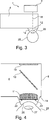
Der Laser
Das OCT-Modul
Der OCT-Scanner
Das OCT-Modul
Der Laserscanner
Ist die Vermessung der ersten Stufe abgeschlossen, wird das Handstück
Folgende optionale Weiterbildungen und Ausgestaltungen kommen für Ausführungsformen des erfindungsgemäßen Systems bzw. Verfahrens zur Justierung in Frage:
Vorzugsweise wird die Markierung im Rahmen eines Beschichtungsprozesses eines optischen Elementes realisiert. Dabei kann die Beschichtung an ausgewählten Stellen durch Maskierung des Substrats gezielt vermieden, oder mit Hilfe einer Sputteranlage anschließend entfernt werden. Beispielsweise kann die Markierung im Rahmen eines Anti-Reflex-Beschichtungsprozesses realisiert werden. An der Stelle der Markierung wird also hiermit einen erhöhte Reflektivität des Substrats für die OCT-Wellenlänge erzielt. The following optional further developments and embodiments are suitable for embodiments of the system or method according to the invention for adjustment:
Preferably, the marking is realized in the context of a coating process of an optical element. In this case, the coating can be selectively avoided at selected locations by masking the substrate, or subsequently removed with the aid of a sputtering system. For example, the marking can be realized in the context of an anti-reflex coating process. Thus, at the location of the marking, an increased reflectivity of the substrate for the OCT wavelength is achieved.
Vorzugsweise liegt die Markierung am Rande bzw. außerhalb der Pupille des Strahlengangs des Behandlungslaserstrahls. The marking is preferably located on the edge or outside the pupil of the beam path of the treatment laser beam.
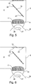
Da die laterale Auflösung der OCT-Aufnahme durch die numerische Apertur der Optik eingeschränkt ist (und typischerweise im Bereich von 10 µm liegt), werden bevorzugt Markierungen mit spezieller Form eingesetzt (siehe
Für die Erfassung der Position dieser Markierungen werden bevorzugt Kantendetektionsalgorithmen eingesetzt, welche eine Formprimitive (z. B. Geraden, Kreise, Bögen, Ellipsen) der Markierung mit Subpixel-Genauigkeit ermitteln können. Edge detection algorithms which can determine a form primitive (eg straight lines, circles, arcs, ellipses) of the marking with subpixel accuracy are preferably used for detecting the position of these markings.
Um die Messgenauigkeit weiter zu erhöhen, weisen die Markierungen bevorzugt eine Punktsymmetrie auf. Da gegenüberliegende Formprimitive mit demselben Abtastungsfehler erfasst werden, bleibt die Berechnung der Position des Symmetrie- bzw. des Mittelpunktes unbeeinflusst von diesem Messfehler. In dieser Art und Weise wird die laterale Position der Markierungselements mit einer Messunsicherheit (MPE – Maximal Permissible Error) ermittelt, welche 5x bis 50x kleiner als eine laterale optische Auflösung des OCT-Moduls ist. In order to further increase the measurement accuracy, the markers preferably have a point symmetry. Since opposite form primitives are detected with the same sampling error, the calculation of the position of the symmetry or of the midpoint unaffected by this measurement error. In this way, the lateral position of the marking element is determined with a measurement uncertainty (MPE - Maximum Permissible Error) which is 5x to 50x smaller than a lateral optical resolution of the OCT module.
Um eine hohe Messgenauigkeit entlang der z-Achse (d. h. parallel zur optischen Hauptachse des OCT-Moduls) zu erzielen, ist bevorzugt die axiale z-Ausdehnung der Markierungen kleiner als 1 µm. Die Realisierung solcher Markierungen ist beispielsweise im Rahmen des oben beschriebenen Beschichtungsverfahrens möglich. In order to achieve a high measuring accuracy along the z-axis (that is to say parallel to the main optical axis of the OCT module), the axial z-dimension of the markings is preferably less than 1 μm. The realization of such markings is possible, for example, in the context of the coating method described above.
Weiterhin sind bevorzugt mehrere Markierungselemente (vorzugsweise 10 oder mehr) auf einer planen Fläche des optischen Elementes angebracht. Furthermore, a plurality of marking elements (preferably 10 or more) are preferably mounted on a flat surface of the optical element.
Die optische Fläche weist bevorzugt eine Planität kleiner als 1 µm auf. Damit kann die Genauigkeit bei der Messung der z-Position und der Kippung des optischen Elementes bzw. der Scaneinheit auf der Basis von statistischen Berechnungen (z. B. Mittelung) erhöht werden. The optical surface preferably has a planarity of less than 1 μm. Thus, the accuracy in measuring the z-position and the tilt of the optical element or the scanning unit can be increased on the basis of statistical calculations (eg, averaging).
Der axiale Messbereich des OCT-Moduls ist durch den Scan-Bereich eingeschränkt. Wenn der Unterschied der optischen Weglängen zwischen dem Auge und der Markierung größer als der axiale Messbereich des OCT-Moduls
In der Bauweise der
Die Markierungselemente weisen bevorzugt eine Formabweichung zwischen 0,01 µm und 10 µm auf (Voraussetzung für die genaue Kantendetektion). The marking elements preferably have a shape deviation between 0.01 .mu.m and 10 .mu.m (requirement for accurate edge detection).
Die Höhe der Markierungselemente liegt bevorzugt zwischen 0,05 µm und 1 µm. The height of the marking elements is preferably between 0.05 μm and 1 μm.
Die Fläche des optischen Elements, welche die Markierungselemente trägt, weist bevorzugt eine Planität zwischen 0,05 µm (entspricht λ/20 bei 1.000 nm) und 1 µm (bzw. λ bei 1.000 nm) auf. The surface of the optical element which carries the marking elements preferably has a planarity between 0.05 μm (corresponds to λ / 20 at 1000 nm) and 1 μm (or λ at 1000 nm).
ZITATE ENTHALTEN IN DER BESCHREIBUNG QUOTES INCLUDE IN THE DESCRIPTION
Diese Liste der vom Anmelder aufgeführten Dokumente wurde automatisiert erzeugt und ist ausschließlich zur besseren Information des Lesers aufgenommen. Die Liste ist nicht Bestandteil der deutschen Patent- bzw. Gebrauchsmusteranmeldung. Das DPMA übernimmt keinerlei Haftung für etwaige Fehler oder Auslassungen.This list of the documents listed by the applicant has been generated automatically and is included solely for the better information of the reader. The list is not part of the German patent or utility model application. The DPMA assumes no liability for any errors or omissions.
Zitierte PatentliteraturCited patent literature
- US 2013/0102895 A1 [0003, 0004, 0037] US 2013/0102895 A1 [0003, 0004, 0037]
- US 8409921 B1 [0003, 0004] US 8409921 B1 [0003, 0004]
- US 2009/0137993 A1 [0005, 0006] US 2009/0137993 A1 [0005, 0006]
- US 2009/0137993 [0005] US 2009/0137993 [0005]
- US 2003/0102895 A1 [0026] US 2003/0102895 A1 [0026]
Claims (10)
Priority Applications (3)
| Application Number | Priority Date | Filing Date | Title |
|---|---|---|---|
| DE102013219829.9A DE102013219829A1 (en) | 2013-09-30 | 2013-09-30 | Method and system for adjusting a laser treatment system on the eye |
| PCT/EP2014/070733 WO2015044402A1 (en) | 2013-09-30 | 2014-09-29 | Method and system for adjusting a laser treatment system to an eye |
| US15/025,875 US10470930B2 (en) | 2013-09-30 | 2014-09-29 | Method and system for adjusting a laser-based treatment system to an eye |
Applications Claiming Priority (1)
| Application Number | Priority Date | Filing Date | Title |
|---|---|---|---|
| DE102013219829.9A DE102013219829A1 (en) | 2013-09-30 | 2013-09-30 | Method and system for adjusting a laser treatment system on the eye |
Publications (1)
| Publication Number | Publication Date |
|---|---|
| DE102013219829A1 true DE102013219829A1 (en) | 2015-04-02 |
Family
ID=51627295
Family Applications (1)
| Application Number | Title | Priority Date | Filing Date |
|---|---|---|---|
| DE102013219829.9A Pending DE102013219829A1 (en) | 2013-09-30 | 2013-09-30 | Method and system for adjusting a laser treatment system on the eye |
Country Status (3)
| Country | Link |
|---|---|
| US (1) | US10470930B2 (en) |
| DE (1) | DE102013219829A1 (en) |
| WO (1) | WO2015044402A1 (en) |
Families Citing this family (1)
| Publication number | Priority date | Publication date | Assignee | Title |
|---|---|---|---|---|
| EP3501463B1 (en) * | 2017-12-20 | 2021-01-13 | Ziemer Ophthalmic Systems AG | Ophthalmological device for treating eye tissue using a pulsed laser beam |
Citations (7)
| Publication number | Priority date | Publication date | Assignee | Title |
|---|---|---|---|---|
| US20030102895A1 (en) | 2001-11-30 | 2003-06-05 | Miller James E. | Low pass filters in DLL circuits |
| US20090137993A1 (en) | 2007-09-18 | 2009-05-28 | Kurtz Ronald M | Methods and Apparatus for Integrated Cataract Surgery |
| DE112008002383T5 (en) * | 2007-09-06 | 2010-06-24 | LenSx Lasers, Inc., Aliso Viejo | Precise targeting of surgical photodisruption |
| US8409921B2 (en) | 2006-01-12 | 2013-04-02 | Stats Chippac Ltd. | Integrated circuit package system including honeycomb molding |
| US20130102895A1 (en) | 2011-10-21 | 2013-04-25 | Optimedica Corporation | Patient interface for ophthalmologic diagnostic and interventional procedures |
| US20130158531A1 (en) * | 2011-12-19 | 2013-06-20 | Ilya Goldshleger | Image processor for intra-surgical optical coherence tomographic imaging of laser cataract procedures |
| WO2013096348A1 (en) * | 2011-12-19 | 2013-06-27 | Alcon Lensx, Inc. | Image processor for intra-surgical optical coherence tomographic imaging of laser cataract procedures |
Family Cites Families (1)
| Publication number | Priority date | Publication date | Assignee | Title |
|---|---|---|---|---|
| US8394084B2 (en) | 2005-01-10 | 2013-03-12 | Optimedica Corporation | Apparatus for patterned plasma-mediated laser trephination of the lens capsule and three dimensional phaco-segmentation |
-
2013
- 2013-09-30 DE DE102013219829.9A patent/DE102013219829A1/en active Pending
-
2014
- 2014-09-29 US US15/025,875 patent/US10470930B2/en active Active
- 2014-09-29 WO PCT/EP2014/070733 patent/WO2015044402A1/en active Application Filing
Patent Citations (7)
| Publication number | Priority date | Publication date | Assignee | Title |
|---|---|---|---|---|
| US20030102895A1 (en) | 2001-11-30 | 2003-06-05 | Miller James E. | Low pass filters in DLL circuits |
| US8409921B2 (en) | 2006-01-12 | 2013-04-02 | Stats Chippac Ltd. | Integrated circuit package system including honeycomb molding |
| DE112008002383T5 (en) * | 2007-09-06 | 2010-06-24 | LenSx Lasers, Inc., Aliso Viejo | Precise targeting of surgical photodisruption |
| US20090137993A1 (en) | 2007-09-18 | 2009-05-28 | Kurtz Ronald M | Methods and Apparatus for Integrated Cataract Surgery |
| US20130102895A1 (en) | 2011-10-21 | 2013-04-25 | Optimedica Corporation | Patient interface for ophthalmologic diagnostic and interventional procedures |
| US20130158531A1 (en) * | 2011-12-19 | 2013-06-20 | Ilya Goldshleger | Image processor for intra-surgical optical coherence tomographic imaging of laser cataract procedures |
| WO2013096348A1 (en) * | 2011-12-19 | 2013-06-27 | Alcon Lensx, Inc. | Image processor for intra-surgical optical coherence tomographic imaging of laser cataract procedures |
Also Published As
| Publication number | Publication date |
|---|---|
| US20160235584A1 (en) | 2016-08-18 |
| US10470930B2 (en) | 2019-11-12 |
| WO2015044402A1 (en) | 2015-04-02 |
Similar Documents
| Publication | Publication Date | Title |
|---|---|---|
| EP0801760B1 (en) | Method of determining the distance between a feature on an object and a surgical microscope and a device for carrying out the method | |
| WO2003105709A1 (en) | Method and instrument for surgical navigation | |
| WO2012119885A1 (en) | Projector device with self-correcting function, and medical device comprising the projector device | |
| DE102013018547B4 (en) | Device for aligning a focusing lens | |
| EP2654636B1 (en) | Device for processing material of a workpiece and method for calibrating such a device | |
| DE10250569A1 (en) | Ophthalmic device and device positioning method | |
| WO2011107584A1 (en) | Diagnostic device for detecting a layer boundary in an eye and ring element for the diagnostic device | |
| DE102018119343B4 (en) | Method for calibrating objects in a reference coordinate system and method for tracking objects | |
| EP2601551A1 (en) | Autofocus system | |
| DE10254369A1 (en) | Ophthalmic device with eye tracker unit | |
| EP2764327A1 (en) | Measuring form changes of a substrate | |
| DE102013219829A1 (en) | Method and system for adjusting a laser treatment system on the eye | |
| WO2019180187A1 (en) | Multi-modal imaging system and method for non-invasive examination of an object to be examined | |
| EP2928280B1 (en) | Measuring mark system for calibrating a machine | |
| WO2015185682A2 (en) | Topography module for opthalmological devices with a distance-independent keratometer and method for the use thereof | |
| EP2767797A1 (en) | Low coherence interferometer and method for spatially resolved optical measurement of the surface profile of an object | |
| WO2010133549A1 (en) | Method and analysis system for measuring a geometry of the eye | |
| DE102017009334B3 (en) | Method for testing an optical system | |
| WO2023134971A1 (en) | Method and apparatus for generating images of an object | |
| WO1998013665A1 (en) | Process and device for measuring a bump on a surface, in particular on the retina of the eye | |
| EP4334769A1 (en) | Microscopy system and method for operating a microscopy system | |
| EP4086686A1 (en) | Microscopy system and method for operating a microscopy system | |
| DE102020212863A1 (en) | System and method for determining patient positioning | |
| WO2012171785A1 (en) | Method for three-dimensionally measuring a body and apparatus | |
| WO2001033166A1 (en) | Automatic contrast focussing with three optical paths |
Legal Events
| Date | Code | Title | Description |
|---|---|---|---|
| R163 | Identified publications notified | ||
| R081 | Change of applicant/patentee |
Owner name: CARL ZEISS MEDITEC AG, DE Free format text: FORMER OWNERS: CARL ZEISS AG, 07745 JENA, DE; CARL ZEISS MEDITEC AG, 07745 JENA, DE |
|
| R082 | Change of representative |
Representative=s name: PATENTANWAELTE GEYER, FEHNERS & PARTNER MBB, DE |
|
| R012 | Request for examination validly filed |