DE102013216552B4 - Device for operating at least one designed as a laser diode light-emitting diode - Google Patents
Device for operating at least one designed as a laser diode light-emitting diode Download PDFInfo
- Publication number
- DE102013216552B4 DE102013216552B4 DE102013216552.8A DE102013216552A DE102013216552B4 DE 102013216552 B4 DE102013216552 B4 DE 102013216552B4 DE 102013216552 A DE102013216552 A DE 102013216552A DE 102013216552 B4 DE102013216552 B4 DE 102013216552B4
- Authority
- DE
- Germany
- Prior art keywords
- voltage
- supply voltage
- terminal
- current
- controllable semiconductor
- Prior art date
- Legal status (The legal status is an assumption and is not a legal conclusion. Google has not performed a legal analysis and makes no representation as to the accuracy of the status listed.)
- Active
Links
Images

Classifications
-
- F—MECHANICAL ENGINEERING; LIGHTING; HEATING; WEAPONS; BLASTING
- F02—COMBUSTION ENGINES; HOT-GAS OR COMBUSTION-PRODUCT ENGINE PLANTS
- F02P—IGNITION, OTHER THAN COMPRESSION IGNITION, FOR INTERNAL-COMBUSTION ENGINES; TESTING OF IGNITION TIMING IN COMPRESSION-IGNITION ENGINES
- F02P23/00—Other ignition
- F02P23/04—Other physical ignition means, e.g. using laser rays
-
- H—ELECTRICITY
- H01—ELECTRIC ELEMENTS
- H01S—DEVICES USING THE PROCESS OF LIGHT AMPLIFICATION BY STIMULATED EMISSION OF RADIATION [LASER] TO AMPLIFY OR GENERATE LIGHT; DEVICES USING STIMULATED EMISSION OF ELECTROMAGNETIC RADIATION IN WAVE RANGES OTHER THAN OPTICAL
- H01S5/00—Semiconductor lasers
- H01S5/02—Structural details or components not essential to laser action
- H01S5/026—Monolithically integrated components, e.g. waveguides, monitoring photo-detectors, drivers
- H01S5/0261—Non-optical elements, e.g. laser driver components, heaters
-
- H—ELECTRICITY
- H01—ELECTRIC ELEMENTS
- H01S—DEVICES USING THE PROCESS OF LIGHT AMPLIFICATION BY STIMULATED EMISSION OF RADIATION [LASER] TO AMPLIFY OR GENERATE LIGHT; DEVICES USING STIMULATED EMISSION OF ELECTROMAGNETIC RADIATION IN WAVE RANGES OTHER THAN OPTICAL
- H01S5/00—Semiconductor lasers
- H01S5/04—Processes or apparatus for excitation, e.g. pumping, e.g. by electron beams
- H01S5/042—Electrical excitation ; Circuits therefor
- H01S5/0428—Electrical excitation ; Circuits therefor for applying pulses to the laser
-
- H—ELECTRICITY
- H01—ELECTRIC ELEMENTS
- H01S—DEVICES USING THE PROCESS OF LIGHT AMPLIFICATION BY STIMULATED EMISSION OF RADIATION [LASER] TO AMPLIFY OR GENERATE LIGHT; DEVICES USING STIMULATED EMISSION OF ELECTROMAGNETIC RADIATION IN WAVE RANGES OTHER THAN OPTICAL
- H01S5/00—Semiconductor lasers
- H01S5/40—Arrangement of two or more semiconductor lasers, not provided for in groups H01S5/02 - H01S5/30
- H01S5/4018—Lasers electrically in series
-
- F—MECHANICAL ENGINEERING; LIGHTING; HEATING; WEAPONS; BLASTING
- F02—COMBUSTION ENGINES; HOT-GAS OR COMBUSTION-PRODUCT ENGINE PLANTS
- F02P—IGNITION, OTHER THAN COMPRESSION IGNITION, FOR INTERNAL-COMBUSTION ENGINES; TESTING OF IGNITION TIMING IN COMPRESSION-IGNITION ENGINES
- F02P7/00—Arrangements of distributors, circuit-makers or -breakers, e.g. of distributor and circuit-breaker combinations or pick-up devices
- F02P7/02—Arrangements of distributors, circuit-makers or -breakers, e.g. of distributor and circuit-breaker combinations or pick-up devices of distributors
-
- H—ELECTRICITY
- H01—ELECTRIC ELEMENTS
- H01S—DEVICES USING THE PROCESS OF LIGHT AMPLIFICATION BY STIMULATED EMISSION OF RADIATION [LASER] TO AMPLIFY OR GENERATE LIGHT; DEVICES USING STIMULATED EMISSION OF ELECTROMAGNETIC RADIATION IN WAVE RANGES OTHER THAN OPTICAL
- H01S5/00—Semiconductor lasers
- H01S5/06—Arrangements for controlling the laser output parameters, e.g. by operating on the active medium
- H01S5/068—Stabilisation of laser output parameters
- H01S5/06808—Stabilisation of laser output parameters by monitoring the electrical laser parameters, e.g. voltage or current
-
- H—ELECTRICITY
- H01—ELECTRIC ELEMENTS
- H01S—DEVICES USING THE PROCESS OF LIGHT AMPLIFICATION BY STIMULATED EMISSION OF RADIATION [LASER] TO AMPLIFY OR GENERATE LIGHT; DEVICES USING STIMULATED EMISSION OF ELECTROMAGNETIC RADIATION IN WAVE RANGES OTHER THAN OPTICAL
- H01S5/00—Semiconductor lasers
- H01S5/40—Arrangement of two or more semiconductor lasers, not provided for in groups H01S5/02 - H01S5/30
- H01S5/4025—Array arrangements, e.g. constituted by discrete laser diodes or laser bar
Landscapes
- Physics & Mathematics (AREA)
- Optics & Photonics (AREA)
- Condensed Matter Physics & Semiconductors (AREA)
- General Physics & Mathematics (AREA)
- Electromagnetism (AREA)
- Engineering & Computer Science (AREA)
- Chemical & Material Sciences (AREA)
- Combustion & Propulsion (AREA)
- Mechanical Engineering (AREA)
- General Engineering & Computer Science (AREA)
- Semiconductor Lasers (AREA)
- Lasers (AREA)
Abstract
Vorrichtung zum Betrieb zumindest einer als Laserdiode ausgebildeten lichtemittierenden Diode (11, 12, 13, 14), die zwischen einem ersten (V+) und einem zweiten (V–) Versorgungsspannungsanschluss in Serie mit der Laststrecke eines steuerbaren Halbleiterelements (T2; T8, T9, T10, T11) und einem Strommesswiderstand (Rs) verschaltet ist, wobei die Versorgungsspannungsanschlüsse (V+, V–) die Ausgangsanschlüsse einer als Gleichspannungshochsetzsteller ausgebildeten Spannungsregelschaltung (15) sind, die eine Versorgungsspannung (Vboost) zur Verfügung stellt, wobei eine Stromregelschaltung (16; 16') für den Strom durch die zumindest eine lichtemittierende Diode (11, 12, 13, 14) vorgesehen ist, deren Stellglied das steuerbare Halbleiterelement ist (T2; T8, T9, T10, T11), dadurch gekennzeichnet, dass die Stromregelschaltung (16') als lineare Stromregelschalturig (Reg_I, Rs, T8, T9, T10, T11) ausgebildet ist und einen zweiten Regler (Reg_I) aufweist, dessen einer Eingang mit dem nicht mit dem zweiten Versorgungsspannungsanschluss (V–) verbundenen Anschluss des Strommesswiderstands (Rs), dessen anderer Eingang mit einer Referenzspannung (Vref_I) und dessen Ausgang mit dem Steuereingang des steuerbaren Halbleiterelements (T8, T9, T10, T11) verbunden ist.Device for operating at least one light-emitting diode (11, 12, 13, 14) designed as a laser diode, which is connected between a first (V +) and a second (V) supply voltage connection in series with the load path of a controllable semiconductor element (T2; T8, T9, T10, T11) and a current sense resistor (Rs), wherein the supply voltage terminals (V +, V-) are the output terminals of a DC voltage step-up voltage regulating circuit (15) providing a supply voltage (Vboost), wherein a current regulating circuit (16; 16 ') for the current through which at least one light-emitting diode (11, 12, 13, 14) is provided whose actuator is the controllable semiconductor element (T2, T8, T9, T10, T11), characterized in that the current regulating circuit (16 ') is designed as a linear Stromregelschalturig (Reg_I, Rs, T8, T9, T10, T11) and has a second controller (Reg_I), whose one input to the non m it the second supply voltage terminal (V-) connected terminal of the current sense resistor (Rs) whose other input to a reference voltage (Vref_I) and its output to the control input of the controllable semiconductor element (T8, T9, T10, T11) is connected.
Description
Im Zug der Verbrauchsoptimierung werden derzeit Brennverfahren für Otto-Motoren entwickelt, die den Wirkungsgrad wesentlich verbessern sollen. Dabei sollen Betriebspunkte des Motors erschlossen werden, die bisher aus technischen Gründen nicht erreichbar waren, wie etwa die starke Abmagerung des Kraftstoffgemisches durch Zuführung eines hohen Abgasanteils (Abgasrückführung) bei gleichzeitig sehr hohem Ladedruck des Turboladers (> 2 Bar). Unter solchen Bedingungen ist das Kraftstoffgemisch zwar noch brennbar, jedoch sehr schwer zu zünden. Auch verzögert der geringe Sauerstoffanteil/hohe Stickstoffanteil den Beginn des endothermen Verbrennungsvorganges nach erfolgter exothermer Zündung, so dass der Zeitpunkt des maximalen Brennraumdruckes stark schwankt. Dies führt in der Folge zu einem unruhigen Motorlauf, wobei Zündaussetzer zu beobachten sind, die der Abmagerung deutliche Grenzen setzen.In the course of optimizing fuel consumption, combustion processes are currently being developed for gasoline engines, which should significantly improve their efficiency. This operating points of the engine are to be developed, which were previously unavailable for technical reasons, such as the strong leaning of the fuel mixture by supplying a high proportion of exhaust gas (exhaust gas recirculation) at the same time very high boost pressure of the turbocharger (> 2 bar). Under such conditions, the fuel mixture is still flammable, but very difficult to ignite. Also, the low oxygen content / high nitrogen content delays the beginning of the endothermic combustion process after the exothermic ignition, so that the time of the maximum combustion chamber pressure varies greatly. As a result, this leads to a turbulent engine run, misfiring being observed, which places clear limits on the emaciation.
Derzeit werden – basierend auf der gebräuchlichen Magnetzündung – Hochleistungszündsysteme eingeführt, deren Zündenergie von derzeit 50 mJ bis 70 mJ auf über 100 mJ gesteigert wurde. Technische Schwierigkeiten sind dabei allerdings eine erhöhte Hochspannungsfestigkeit wegen des höheren Zünddruckes und der erhöhte Elektrodenverschleiß der Zündkerzen, was in den erhöhten Zündströmen begründet ist. Alternativ wurden in der Vergangenheit bereits Zündkonzepte untersucht, bei denen die Entflammung des Kraftstoffgemisches auf der Erzeugung sehr kurzer, extrem energiereicher Laserpulse im Brennraum beruht. Dabei konnte gezeigt werden, dass sich solch eine Laserzündung besonders gut für die oben beschriebenen schwierigen Zündbedingungen eignet. Dies ist beispielsweise in dem Artikel „Konzeption und Entwicklung einer Laserzündkerze” von Heinrich Kofler, Johannes Tauer, Ernst Wintner, Institut für Photonik, TU Wien beschrieben.Currently, high-performance ignition systems are being introduced based on the current magneto-ignition system. Their ignition energy has been increased from currently 50 mJ to 70 mJ to more than 100 mJ. Technical difficulties are, however, an increased high-voltage strength due to the higher ignition pressure and the increased electrode wear of the spark plugs, which is due to the increased ignition currents. Alternatively, ignition concepts have already been investigated in the past in which the ignition of the fuel mixture is based on the generation of very short, extremely high-energy laser pulses in the combustion chamber. It could be shown that such a laser ignition is particularly well suited for the difficult ignition conditions described above. This is described, for example, in the article "Conception and Development of a Laser Spark Plug" by Heinrich Kofler, Johannes Tauer, Ernst Wintner, Institute for Photonics, Vienna University of Technology.
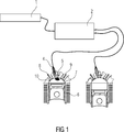
Ein Laserzündsystem besteht aus einem oder mehreren Halbleiterlasern, die als Pumplaser verwendet werden und kurze Laserpulse von ca. 300 μs Dauer abstrahlen. Eine Glasfaser leitet die Lichtpulse zu einer im Motor eingebauten Laserzündkerze, die aus einem Neodym YAG-Laser besteht, der zum Brennraum hin mit einem Güteschalter, einer Fokussieroptik und einem optischen Fenster versehen ist. Ist das Inversionsniveau des Neodym YAG-Lasers vollständig besetzt, bleicht der Güteschalter aus und die optische Energie entweicht in Richtung Brennraum als extrem kurzer Impuls von wenigen Nanosekunden Dauer. Die Optik fokussiert den Puls innerhalb des Brennraumes und die dabei entstehende Energie führt zu nicht resonanter Ionisation der Gemischmoleküle. Dies geschieht umso effizienter, je höher die Teilchendichte, d. h. je höher der Zünddruck ist. üblicherweise wird für jeden Zylinder des Verbrennungsmotors ein Pumplaser, eine Glasfaser und eine Laserzündkerze verwendet. Mittels eines geeigneten Halbleiterschalters wird zur Zündung der jeweils entsprechende Pumplaser aktiviert. Die elektrische Leistung zum Betrieb liegt im Mittel bei etwa 100 W, jedoch ist während des Pumppulses eine Momentanleistung von bis zu 2 KW erforderlich. Heute verfügbare Lasermodule haben eine Betriebsspannung von typisch 9 bis 12 V, was Betriebsströme von bis zu 250 A erforderlich macht, wobei bei manchen Lasermodulen mehrere Laser zu einem Modul zusammengefasst werden, um die erforderliche Leistung zu erreichen.A laser ignition system consists of one or more semiconductor lasers, which are used as a pump laser and emit short laser pulses of about 300 μs duration. A glass fiber conducts the light pulses to a built-in motor laser spark plug, which consists of a neodymium YAG laser, which is provided to the combustion chamber with a Q-switch, a focusing optics and an optical window. When the inversion level of the neodymium YAG laser is fully occupied, the Q-switch fades and the optical energy escapes towards the combustion chamber as an extremely short pulse of a few nanoseconds. The optics focuses the pulse within the combustion chamber and the resulting energy leads to non-resonant ionization of the mixture molecules. This is the more efficient, the higher the particle density, ie. H. the higher the ignition pressure. Usually, a pump laser, a glass fiber and a laser spark plug are used for each cylinder of the internal combustion engine. By means of a suitable semiconductor switch, the respectively corresponding pump laser is activated for ignition. On average, the electrical power for operation is about 100 W, but an instantaneous power of up to 2 KW is required during the pumping pulse. Today's laser modules have an operating voltage of typically 9 to 12 V, which requires operating currents of up to 250 A, with some laser modules combining several lasers into one module in order to achieve the required performance.
Die
Zum Ein- und Ausschalten von in Serie angeordneten Leuchtdioden für die Hintergrundbeleuchtung in Displays ist aus der
Für die Ansteuerung von als Kraftstoffeinspritzventilen verwendeten Piezoaktoren sind hohe Spannungen erforderlich, um eine schnelle Aufladung und damit kurze Einspritzzeit zu ermöglichen. Die derzeit realisierten Spannungen von etwa 200 bis 250 V und die für eine präzise Einspritzmenge erforderliche Laderegelung wird gemäß der
Die
Auch die
In der
Die Aufgabe der Erfindung ist es demgegenüber, eine Vorrichtung zum Betrieb zumindest einer lichtemittierenden Diode anzugeben, die eine ausreichende Leistung zum Pumpen von Laserzündkerzen bei geringem Strom ermöglicht.The object of the invention is in contrast to provide a device for operating at least one light-emitting diode, which allows sufficient power for pumping laser spark plugs at low power.
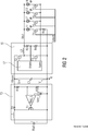
Die Aufgabe wird gelöst, durch eine Vorrichtung zum Betrieb zumindest einer als Laserdiode ausgebildeten lichtemittierenden Diode, die zwischen einem ersten und einem zweiten Versorgungsspannungsanschluss in Serie mit der Laststrecke eines steuerbaren Halbleiterelements und einem Strommesswiderstand verschaltet ist, wobei die Versorgungsspannungsanschlüsse die Ausgangsanschlüsse einer als Gleichspannungshochsetzsteller ausgebildeten Spannungsregelschaltung sind, die eine Versorgungsspannung zur Verfügung stellt, wobei eine Stromregelschaltung für den Strom durch die zumindest eine lichtemittierende Diode vorgesehen ist, deren Stellglied das steuerbare Halbleiterelement ist, und wobei die Stromregelschaltung als lineare Stromregelschaltung ausgebildet ist und einen zweiten Regler aufweist, dessen einer Eingang mit dem nicht mit dem zweiten Versorgungsspannungsanschluss verbundenen Anschluss des Strommesswiderstands, dessen anderer Eingang mit einer Referenzspannung und dessen Ausgang mit dem Steuereingang des steuerbaren Halbleiterelements verbunden ist.The object is achieved by a device for operating at least one formed as a laser diode light-emitting diode, which is connected between a first and a second supply voltage terminal in series with the load path of a controllable semiconductor element and a current measuring resistor, wherein the supply voltage terminals, the output terminals of a DC voltage boost converter formed voltage control circuit are, which provides a supply voltage, wherein a current regulating circuit for the current through the at least one light emitting diode is provided, whose actuator is the controllable semiconductor element, and wherein the current control circuit is designed as a linear current control circuit and having a second controller, whose one input with the not connected to the second supply voltage terminal terminal of the current measuring resistor whose other input to a reference voltage and its output ng is connected to the control input of the controllable semiconductor element.
In erfindungsgemäßer Weise weist die Vorrichtung zum Betrieb einer Laserdiode einen Gleichspannungshochsetzsteller auf, der die Spannung einer Kraftfahrzeugbatterie von etwa 12 bis 14 V Nominalspannung in eine Betriebsspannung von etwa 200 V hochsetzt, wodurch sich der Betriebsstrom auf 20 A reduzieren lässt. Für diesen Spannungs-/Strombereich existieren zahlreiche, kostengünstige Halbleiter, so dass sich hier ein besonders vorteilhafter Betrieb erzielen lässt. Durch die erfindungsgemäße Vorrichtung wird der Betriebsstrom für ein Lasermodul von etwa 10 A für die Dauer von 300 μs aus einem Speicherkondensator bereitgestellt, der am Ausgang der Spannungsregelschaltung verschaltet ist. Dies ist mit handelsüblichen Elektrolydkondensatoren problemlos möglich. Der Gleichspannungshochsetzsteller arbeitet kontinuierlich und muss nur die dem Speicherkondensator entnommene Energie nachliefern. Die Dauerleistung liegt dabei z. B. bei 100 W. Diese Gleichspannungshochsetzsteller dient bezüglich der Laserstrompulse als aktives Filter für das Bordnetz. Lediglich sein dreiecksförmiger Betriebsstrom von z. B. 10 Ass macht eine – allerdings wesentlich kostengünstigere – Filterung der Batteriezuleitung notwendig, als dies bei Strömen von 200 bis 250 A erforderlich wäre.According to the invention, the apparatus for operating a laser diode on a DC boost converter, which raises the voltage of a motor vehicle battery of about 12 to 14 V nominal voltage in an operating voltage of about 200 V, whereby the operating current can be reduced to 20 A. For this voltage / current range, there are numerous, cost-effective semiconductors, so that a particularly advantageous operation can be achieved here. By the device according to the invention the operating current for a laser module of about 10 A for the duration of 300 microseconds is provided from a storage capacitor which is connected at the output of the voltage regulation circuit. This is easily possible with commercial Elektrolydkondensatoren. The DC boost converter operates continuously and only has to supply the energy taken from the storage capacitor. The continuous power is z. B. at 100 W. This DC boost converter is used with respect to the laser current pulses as an active filter for the electrical system. Only his triangular operating current of z. B. 10 Ace requires filtering of the battery feed, albeit at a much lower cost, than would be required for currents of 200 to 250 amps.
Da die Betriebsspannung von Laserdioden abhängig von Temperatur, Alterung, Fertigungstoleranzen etc. schwankt, ist es sinnvoll, den Laser mittels einer Stromregelung zu versorgen, wobei sich die Batteriespannung dann ergibt. Da sich die Spannung am Speicherkondensator des Gleichspannungshochsetzstellers nicht schnell genug verändern lässt,
ist eine Stromregelschaltung zur Regelung des Laserdiodenstroms als lineare Stromregelschaltung ausgebildet und weist einen zweiten Regler auf, dessen einer Eingang mit dem nicht mit dem zweiten Versorgungsspannungsanschluss verbundenen Anschluss des Strommesswiderstands, dessen anderer Eingang mit einer Referenzspannung und dessen Ausgang mit dem Steuereingang des steuerbaren Halbleiterelements verbunden ist.Since the operating voltage of laser diodes varies depending on temperature, aging, manufacturing tolerances, etc., it makes sense to provide the laser by means of a current control, the battery voltage then results. Since the voltage at the storage capacitor of the DC voltage booster can not be changed fast enough,
a current control circuit for controlling the laser diode current is designed as a linear current control circuit and has a second controller whose one input is connected to the not connected to the second supply voltage terminal terminal of the current measuring resistor whose other input is connected to a reference voltage and whose output to the control input of the controllable semiconductor element ,
In einer vorteilhaften Weiterbildung der Erfindung sind zumindest zwei lichtemittierende Dioden vorgesehen, die jeweils in Serie mit einem steuerbaren Halbleiterelement geschaltet und mit ihren Anoden mit dem ersten Versorgungsspannungsanschluss verbunden sind, wobei der nicht mit der lichtemittierenden Diode verbundene Anschluss des jeweiligen steuerbaren Halbleiterelements mit dem nicht mit dem zweiten Versorgungsanschluss verbundenen Anschluss des Strommesswiderstands verbunden ist und wobei ein erster Multiplexer vorgesehen ist, über den der Ausgang des zweiten Reglers mit den Steuereingängen der zumindest zwei steuerbaren Halbleiterelemente verbunden ist.In an advantageous development of the invention, at least two light-emitting diodes are provided which are each connected in series with a controllable semiconductor element and connected with their anodes to the first supply voltage terminal, wherein the not connected to the light-emitting diode terminal of the respective controllable semiconductor element with the not connected to the second supply terminal connection of the current sense resistor is connected and wherein a first multiplexer is provided, via which the output of the second regulator is connected to the control inputs of the at least two controllable semiconductor elements.
In vorteilhafter Weise können die Auswahltransistoren bei zueinander parallel geschalteten Lasermodulen als Stellglieder für die lineare Stromregelschaltung verwendet werden. Dabei wird durch den Multiplexer zum einen festgelegt, welches Lasermodul aktiviert werden soll und andererseits der Regler mit den zugeordneten als Stellglied fungierenden Auswahlschalter verbunden.Advantageously, the selection transistors may be used as mutually parallel laser modules as actuators for the linear current control circuit. It is determined by the multiplexer on the one hand, which laser module should be activated and on the other hand, the controller connected to the associated acting as an actuator selector switch.
In einer Weiterbildung der Erfindung sind die Verbindungsknoten der zumindest zwei lichtemittierenden Dioden und der ihnen zugeordneten Halbleiterelemente über einen zweiten Multiplexer mit einem ersten Eingangsanschluss eines dritten Reglers der Spannungsregelschaltung verbunden.In a development of the invention, the connection nodes are the at least two light-emitting diodes and their associated semiconductor elements via a second multiplexer to a first input terminal of a third regulator of the voltage regulation circuit.
Durch diesen Spannungsregelkreis wird dafür gesorgt, dass die Spannung an dem Stellglied Halbleiterelementen bzw. den Auswahlhalbleiterelementen auf einen vorgegebenen Minimalwert geregelt wird, bzw. diesen nicht unterschreitet. Dadurch wird erreicht, dass einerseits alle Lasermodule mit einem geregelten Strom betrieben werden und gleichzeitig die Spannung an den – als Stromquellen betriebenen – Auswahl Halbleiterelementen so gering wie möglich ist, um unnötige Verlustleistung zu vermeiden.By this voltage control loop is ensured that the voltage at the actuator semiconductor elements or the selection semiconductor elements is controlled to a predetermined minimum value, or this does not fall below. This ensures that on the one hand all laser modules are operated with a regulated current and at the same time the voltage at the - operated as a current source - selection semiconductor elements is as low as possible in order to avoid unnecessary power loss.
In einer Weiterbildung der Erfindung ist zwischen den Versorgungsspannungsanschlüssen die Serienschaltung eines ersten und eines zweiten Spannungsteilerwiderstandes verschaltet, deren Verbindungspunkt mit einem zweiten Eingangsanschluss des dritten Reglers der Spannungsreglerschaltung verbunden ist. Damit kann dafür gesorgt werden, dass die Ausgangsspannung der Spannungsregelschaltung einen vorgegebenen Maximalwert nicht überschreitet, wodurch eine unnötige Verlustleistung vermieden wird.In one development of the invention, the series connection of a first and a second voltage divider resistor is connected between the supply voltage terminals, whose connection point is connected to a second input terminal of the third regulator of the voltage regulator circuit. This can ensure that the output voltage of the voltage regulating circuit does not exceed a predetermined maximum value, whereby unnecessary power loss is avoided.
Die Erfindung soll nachfolgend anhand eines Ausführungsbeispiels mit Hilfe von Figuren näher erläutert werden. Dabei zeigen:The invention will be explained in more detail using an exemplary embodiment with the aid of figures. Showing:
Eine Vorrichtung mit gepulster Ansteuerung eines solchen Laserdiodenmoduls, das im Folgenden lediglich als Laserdiode bezeichnet wird, ist in der
Die Spannungsregelschaltung
Im in der
Da diese Laserdioden
Eine geschaltete Stromregelschaltung
Die Vorrichtung gemäß dem in der
Die erfindungsgemäße Vorrichtung der
Beim Spannungsregler
Die Versorgungsspannung Vboost wird im Ausführungsbeispiel der
Die steuerbaren Halbleiterelemente T8 bis T11 dienen im Ausführungsbeispiel der
Über den ersten Multiplexer Mux_I wird durch entsprechende Verbindungsleitungen zu den Steueranschlüssen der steuerbaren Halbleiterelemente T8 bis T11 einerseits eine zu betreibende Laserdiode
Die Verbindungsknoten der Laserdioden
Durch die erfindungsgemäßen Vorrichtung zum Betrieb zumindest einer Laserdiode, die als Pumplaser für eine Laserzündkerze in einem Verbrennungsmotor eines Kraftfahrzeuges dienen soll, ist eine kostengünstige Realisierung vorgeschlagen, da aufgrund einer hohen Betriebsspannung zum Erreichen einer vorgegebenen Leistung nur ein geringer Strom nötig ist und daher auf entsprechend teure Schalttransistoren und Filterelemente, wie sie bei hohen Strömen erforderlich sind, verzichtet werden kann.The inventive device for operating at least one laser diode, which is to serve as a pump laser for a laser spark plug in an internal combustion engine of a motor vehicle, a cost-effective implementation is proposed because due to a high operating voltage to achieve a given power only a small amount of power is needed and therefore to accordingly expensive switching transistors and filter elements, as required at high currents, can be dispensed with.
Claims (5)
Priority Applications (2)
| Application Number | Priority Date | Filing Date | Title |
|---|---|---|---|
| DE102013216552.8A DE102013216552B4 (en) | 2013-08-21 | 2013-08-21 | Device for operating at least one designed as a laser diode light-emitting diode |
| US14/464,882 US9677533B2 (en) | 2013-08-21 | 2014-08-21 | Apparatus for operating at least one light-emitting diode in the form of a laser diode |
Applications Claiming Priority (1)
| Application Number | Priority Date | Filing Date | Title |
|---|---|---|---|
| DE102013216552.8A DE102013216552B4 (en) | 2013-08-21 | 2013-08-21 | Device for operating at least one designed as a laser diode light-emitting diode |
Publications (2)
| Publication Number | Publication Date |
|---|---|
| DE102013216552A1 DE102013216552A1 (en) | 2015-02-26 |
| DE102013216552B4 true DE102013216552B4 (en) | 2017-07-06 |
Family
ID=52446702
Family Applications (1)
| Application Number | Title | Priority Date | Filing Date |
|---|---|---|---|
| DE102013216552.8A Active DE102013216552B4 (en) | 2013-08-21 | 2013-08-21 | Device for operating at least one designed as a laser diode light-emitting diode |
Country Status (2)
| Country | Link |
|---|---|
| US (1) | US9677533B2 (en) |
| DE (1) | DE102013216552B4 (en) |
Families Citing this family (7)
| Publication number | Priority date | Publication date | Assignee | Title |
|---|---|---|---|---|
| DE102015119216A1 (en) | 2015-11-09 | 2017-05-11 | Volkswagen Ag | Ignition device for an internal combustion engine |
| AT518968B1 (en) * | 2016-07-08 | 2019-05-15 | Ge Jenbacher Gmbh & Co Og | Control device for a plurality of actuators of an internal combustion engine |
| DE102016116368B4 (en) | 2016-09-01 | 2024-03-21 | OSRAM Opto Semiconductors Gesellschaft mit beschränkter Haftung | Driver circuit for at least one light-emitting component and control method |
| JP7021618B2 (en) * | 2018-08-10 | 2022-02-17 | オムロン株式会社 | Manufacturing method of laser diode array device, laser emission circuit and ranging device |
| JP2020088020A (en) * | 2018-11-16 | 2020-06-04 | ソニーセミコンダクタソリューションズ株式会社 | Detection circuit, drive circuit, and light-emitting device |
| US11728621B2 (en) * | 2019-06-05 | 2023-08-15 | Stmicroelectronics (Research & Development) Limited | Voltage controlled steered VCSEL driver |
| US11579290B2 (en) | 2019-06-05 | 2023-02-14 | Stmicroelectronics (Research & Development) Limited | LIDAR system utilizing multiple networked LIDAR integrated circuits |
Citations (5)
| Publication number | Priority date | Publication date | Assignee | Title |
|---|---|---|---|---|
| US5736881A (en) * | 1994-12-05 | 1998-04-07 | Hughes Electronics | Diode drive current source |
| EP1139443A1 (en) * | 2000-04-01 | 2001-10-04 | Robert Bosch GmbH | Method and apparatus for driving a piezoelectric fuel injector element |
| DE102006036167A1 (en) * | 2006-08-01 | 2008-02-14 | Laserline Gesellschaft für Entwicklung und Vertrieb von Diodenlasern mbH | Circuit arrangement e.g. for pulsed current drive of laser diode arrangement, has DC voltage source included in charge-current circuit based on inductance forming part of resonance circuit |
| DE102007041839A1 (en) * | 2007-09-03 | 2009-03-05 | Robert Bosch Gmbh | Energy supply unit for the electrical power supply of at least one consumer |
| DE202009008337U1 (en) * | 2009-06-12 | 2009-08-27 | Picolas Gmbh | Device for controlling a laser diode array |
Family Cites Families (6)
| Publication number | Priority date | Publication date | Assignee | Title |
|---|---|---|---|---|
| US7087882B1 (en) * | 2002-10-31 | 2006-08-08 | Finisar Corporation | Controlling the dynamic range of an avalanche photodiode |
| US8378957B2 (en) | 2008-04-28 | 2013-02-19 | Atmel Corporation | Methods and circuits for triode region detection |
| US8581810B2 (en) | 2008-03-11 | 2013-11-12 | Atmel Corporation | Methods and circuits for self-calibrating controller |
| US8493300B2 (en) | 2008-03-11 | 2013-07-23 | Atmel Corporation | Architecture and technique for inter-chip communication |
| US8314572B2 (en) | 2008-06-24 | 2012-11-20 | Atmel Corporation | Apparatus and methodology for enhancing efficiency of a power distribution system having power factor correction capability by using a self-calibrating controller |
| US8441199B2 (en) | 2009-03-23 | 2013-05-14 | Atmel Corporation | Method and apparatus for an intelligent light emitting diode driver having power factor correction capability |
-
2013
- 2013-08-21 DE DE102013216552.8A patent/DE102013216552B4/en active Active
-
2014
- 2014-08-21 US US14/464,882 patent/US9677533B2/en active Active
Patent Citations (5)
| Publication number | Priority date | Publication date | Assignee | Title |
|---|---|---|---|---|
| US5736881A (en) * | 1994-12-05 | 1998-04-07 | Hughes Electronics | Diode drive current source |
| EP1139443A1 (en) * | 2000-04-01 | 2001-10-04 | Robert Bosch GmbH | Method and apparatus for driving a piezoelectric fuel injector element |
| DE102006036167A1 (en) * | 2006-08-01 | 2008-02-14 | Laserline Gesellschaft für Entwicklung und Vertrieb von Diodenlasern mbH | Circuit arrangement e.g. for pulsed current drive of laser diode arrangement, has DC voltage source included in charge-current circuit based on inductance forming part of resonance circuit |
| DE102007041839A1 (en) * | 2007-09-03 | 2009-03-05 | Robert Bosch Gmbh | Energy supply unit for the electrical power supply of at least one consumer |
| DE202009008337U1 (en) * | 2009-06-12 | 2009-08-27 | Picolas Gmbh | Device for controlling a laser diode array |
Also Published As
| Publication number | Publication date |
|---|---|
| DE102013216552A1 (en) | 2015-02-26 |
| US20150053163A1 (en) | 2015-02-26 |
| US9677533B2 (en) | 2017-06-13 |
Similar Documents
| Publication | Publication Date | Title |
|---|---|---|
| DE102013216552B4 (en) | Device for operating at least one designed as a laser diode light-emitting diode | |
| DE102013102529B4 (en) | Method for controlling a spark gap, in particular a spark plug | |
| DE2522283C3 (en) | Device for starting and / or post-starting enrichment of the fuel-air mixture fed to an internal combustion engine and formed by means of an electric fuel injection system | |
| DE1451956B2 (en) | FUEL INJECTION DEVICE FOR COMBUSTION MACHINERY | |
| DE102005035665A1 (en) | Ignition system for an internal combustion engine | |
| DE102007000078A1 (en) | Multiple-cycle ignition control device and method for internal combustion engines | |
| DE102013217037B3 (en) | Device for charging and discharging a capacitive actuator and arrangement with such a device | |
| EP1186102B1 (en) | Method and device for the open-load diagnosis of a switching stage | |
| WO2015071047A1 (en) | Ignition system and method for operating an ignition system | |
| DE102011006268A1 (en) | Method and device for extending the burning time of a spark ignited by a spark plug in an internal combustion engine | |
| DE102016221656B4 (en) | IGNITION CONTROL DEVICE AND IGNITION CONTROL METHOD FOR INTERNAL COMBUSTION ENGINE | |
| DE2745294A1 (en) | THRESHOLD CIRCUIT FOR AN ELECTRONIC IGNITION SYSTEM | |
| DE112014003208T5 (en) | ignition control device | |
| DE102014216044A1 (en) | Ignition system and method for operating an ignition system | |
| EP3069010A1 (en) | Ignition system and method for operating an ignition system | |
| EP0827569B1 (en) | Inductive ignition device | |
| DE112018004889T5 (en) | IGNITION SYSTEM | |
| DE102008061586B4 (en) | Method and device for controlling a solid state actuator | |
| EP0852895B1 (en) | Fixed-cycle power-supply circuit with an at least temporarily active consumer-independent load | |
| DE3404245A1 (en) | High-voltage generator circuit for a motor vehicle ignition system | |
| WO2009037058A1 (en) | Method for the operation of an ignition device | |
| DE102015200021B4 (en) | FUEL INJECTOR CONTROL DEVICE | |
| DE102016202601A1 (en) | Ignition system for an internal combustion engine | |
| DE102016217056A1 (en) | Voltage-dependent operation of individual light sources | |
| DE102015110068A1 (en) | ignition system |
Legal Events
| Date | Code | Title | Description |
|---|---|---|---|
| R012 | Request for examination validly filed | ||
| R016 | Response to examination communication | ||
| R016 | Response to examination communication | ||
| R016 | Response to examination communication | ||
| R018 | Grant decision by examination section/examining division | ||
| R020 | Patent grant now final | ||
| R081 | Change of applicant/patentee |
Owner name: VITESCO TECHNOLOGIES GMBH, DE Free format text: FORMER OWNER: CONTINENTAL AUTOMOTIVE GMBH, 30165 HANNOVER, DE |
|
| R081 | Change of applicant/patentee |
Owner name: VITESCO TECHNOLOGIES GMBH, DE Free format text: FORMER OWNER: VITESCO TECHNOLOGIES GMBH, 30165 HANNOVER, DE |
|
| R084 | Declaration of willingness to licence |